EP4476779B1 - Verfahren und einheit zur herstellung einer zelle für eine elektrische batterie - Google Patents
Verfahren und einheit zur herstellung einer zelle für eine elektrische batterie Download PDFInfo
- Publication number
- EP4476779B1 EP4476779B1 EP24725257.0A EP24725257A EP4476779B1 EP 4476779 B1 EP4476779 B1 EP 4476779B1 EP 24725257 A EP24725257 A EP 24725257A EP 4476779 B1 EP4476779 B1 EP 4476779B1
- Authority
- EP
- European Patent Office
- Prior art keywords
- holding element
- electrode
- separator film
- axis
- holding
- Prior art date
- Legal status (The legal status is an assumption and is not a legal conclusion. Google has not performed a legal analysis and makes no representation as to the accuracy of the status listed.)
- Active
Links
Images

Classifications
-
- H—ELECTRICITY
- H01—ELECTRIC ELEMENTS
- H01M—PROCESSES OR MEANS, e.g. BATTERIES, FOR THE DIRECT CONVERSION OF CHEMICAL ENERGY INTO ELECTRICAL ENERGY
- H01M4/00—Electrodes
- H01M4/02—Electrodes composed of, or comprising, active material
- H01M4/04—Processes of manufacture in general
- H01M4/0402—Methods of deposition of the material
- H01M4/0407—Methods of deposition of the material by coating on an electrolyte layer
-
- H—ELECTRICITY
- H01—ELECTRIC ELEMENTS
- H01M—PROCESSES OR MEANS, e.g. BATTERIES, FOR THE DIRECT CONVERSION OF CHEMICAL ENERGY INTO ELECTRICAL ENERGY
- H01M10/00—Secondary cells; Manufacture thereof
- H01M10/04—Construction or manufacture in general
-
- H—ELECTRICITY
- H01—ELECTRIC ELEMENTS
- H01M—PROCESSES OR MEANS, e.g. BATTERIES, FOR THE DIRECT CONVERSION OF CHEMICAL ENERGY INTO ELECTRICAL ENERGY
- H01M10/00—Secondary cells; Manufacture thereof
- H01M10/04—Construction or manufacture in general
- H01M10/0404—Machines for assembling batteries
-
- H—ELECTRICITY
- H01—ELECTRIC ELEMENTS
- H01M—PROCESSES OR MEANS, e.g. BATTERIES, FOR THE DIRECT CONVERSION OF CHEMICAL ENERGY INTO ELECTRICAL ENERGY
- H01M10/00—Secondary cells; Manufacture thereof
- H01M10/04—Construction or manufacture in general
- H01M10/045—Cells or batteries with folded plate-like electrodes
-
- H—ELECTRICITY
- H01—ELECTRIC ELEMENTS
- H01M—PROCESSES OR MEANS, e.g. BATTERIES, FOR THE DIRECT CONVERSION OF CHEMICAL ENERGY INTO ELECTRICAL ENERGY
- H01M10/00—Secondary cells; Manufacture thereof
- H01M10/05—Accumulators with non-aqueous electrolyte
- H01M10/058—Construction or manufacture
- H01M10/0583—Construction or manufacture of accumulators with folded construction elements except wound ones, i.e. folded positive or negative electrodes or separators, e.g. with "Z"-shaped electrodes or separators
-
- Y—GENERAL TAGGING OF NEW TECHNOLOGICAL DEVELOPMENTS; GENERAL TAGGING OF CROSS-SECTIONAL TECHNOLOGIES SPANNING OVER SEVERAL SECTIONS OF THE IPC; TECHNICAL SUBJECTS COVERED BY FORMER USPC CROSS-REFERENCE ART COLLECTIONS [XRACs] AND DIGESTS
- Y02—TECHNOLOGIES OR APPLICATIONS FOR MITIGATION OR ADAPTATION AGAINST CLIMATE CHANGE
- Y02E—REDUCTION OF GREENHOUSE GAS [GHG] EMISSIONS, RELATED TO ENERGY GENERATION, TRANSMISSION OR DISTRIBUTION
- Y02E60/00—Enabling technologies; Technologies with a potential or indirect contribution to GHG emissions mitigation
- Y02E60/10—Energy storage using batteries
-
- Y—GENERAL TAGGING OF NEW TECHNOLOGICAL DEVELOPMENTS; GENERAL TAGGING OF CROSS-SECTIONAL TECHNOLOGIES SPANNING OVER SEVERAL SECTIONS OF THE IPC; TECHNICAL SUBJECTS COVERED BY FORMER USPC CROSS-REFERENCE ART COLLECTIONS [XRACs] AND DIGESTS
- Y02—TECHNOLOGIES OR APPLICATIONS FOR MITIGATION OR ADAPTATION AGAINST CLIMATE CHANGE
- Y02P—CLIMATE CHANGE MITIGATION TECHNOLOGIES IN THE PRODUCTION OR PROCESSING OF GOODS
- Y02P70/00—Climate change mitigation technologies in the production process for final industrial or consumer products
- Y02P70/50—Manufacturing or production processes characterised by the final manufactured product
Definitions
- the invention relates to the field of rechargeable electric batteries for electric motor vehicles.
- the invention relates to the manufacture of electric cells intended to equip electric batteries.
- the invention relates to a method and a unit for manufacturing lithium-ion electrochemical cells of the "pouch" type, i.e. cells in sachets.
- Electric cells known as "pouch” type cells, intended to equip rechargeable electric batteries can be manufactured in different ways.
- One way to make these cells is to cut and then deposit electrodes of opposite polarity on top of each other, separating them with an insulating separator film.
- the separator film is unwound as the electrodes are deposited on said separator film.
- the separator film is first unwound.
- a first electrode is deposited.
- the separator film is again unwound to cover the first electrode.
- a second electrode of polarity opposite to the first electrode is deposited on the separator film.
- the separator film is then unwound again to cover the second electrode.
- the method After the operation of depositing an electrode and before unrolling the separator film to cover said deposited electrode, the method generally comprises an operation of holding the electrode with holding elements. At least two holding elements press the electrode against the separator film and then the separator film is unrolled onto the electrode thus plated to cover it. Once the separator film is unrolled, the holding elements are removed to plate other electrodes.
- the holding elements clamp the electrodes at the lateral ends to ensure that the mechanically tensioned separator does not damage or carry the electrode away during unwinding, given that the electrode is thin and deformable.
- the separating film which is mechanically stretched, is in contact with the holding elements because the said separating film is folded around the holding elements. It happens, when removing the retaining elements, they damage the separator film by friction. The separator film is then scratched or even torn.
- a damaged separator film can cause very serious accidents such as fire or explosion if the defect is not detected early enough.
- the invention aims to solve this drawback.
- the eighth removal operation which comprises a first lateral movement along the first axis, advantageously prevents damage to the separator film.
- the first holding element and the second holding element are tightly clamped by the separator film at the end of the fourth operation. Thanks to the first lateral movement along the first axis, the first and second holding elements can be released from the separator film without damaging it.
- a first electrode 1 and a second electrode 2 of polarity opposite to the first electrode 1 are respectively represented, pressed against a separator film 3.
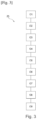
- the method 25 comprises a first operation O1 of unwinding a separator film 3.
- This first operation O1 is carried out by means of an unwinding device (not shown in the drawings).
- the separator film 3 is initially wound into a reel and the unwinding device unwinds it as the electrodes 1, 2 are stacked on top of each other.
- the unwinding device is in the form of a carriage performing a back and forth movement along the first axis X.
- the method 25 comprises a second O2 operation of deposition on the separator film 3 of the first electrode 1.
- the first electrode 1 has a substantially rectangular, non-limiting shape.
- the method 25 comprises a third operation O3 of holding on the separator film 3, on the one hand, the first lateral edge 4 and the first longitudinal edge 6 and, on the other hand, the second lateral edge 5 and the first longitudinal edge 6 of the first electrode 1.
- the third holding operation O3 is carried out by means of a first holding element 8 and a second holding element 10.
- the method 25 comprises a fourth operation O4 of unwinding the separator film 3. During the fourth operation O4, the separator film 3 is unwound to cover the first electrode 1.
- the method 25 comprises a fifth operation O5 of depositing the second electrode 2 on the separator film 3.
- the second electrode 2 is arranged substantially opposite the first electrode 1.
- the method 25 comprises a sixth operation O6 of holding on the separator film 3, on the one hand, the third lateral edge 18 and the third longitudinal edge 20 and, on the other hand, the fourth lateral edge 19 and the third longitudinal edge 20 of the second electrode 2.
- the sixth holding operation O6 is carried out by means of a third holding element 11 and a fourth holding element 12.
- the method 25 comprises a seventh operation O7 of unwinding the separator film 3 to cover the second electrode 2.
- the method 25 comprises an eighth operation O8 of removing the first holding element 8 and the second holding element 10.
- the method 25 comprises a ninth operation O9 of removing the third holding element 11 and the fourth holding element 12.
- the first, second, third, fourth, fifth, sixth, seventh, eighth and ninth operations O1 - O9 are repeated several times. Thus it becomes possible to obtain a stack of electrodes 1, 2 separated by a separator film 3. It should be noted that the operations are not necessarily carried out in the order established above. Indeed, technical adaptations of the aforementioned method 25 are likely to modify the order of the operations without this having any influence on the invention.
- the eighth O8 withdrawal operation successively includes a first lateral movement 13 and a first movement 14 of distance.
- the first holding element 8 and the second holding element 10 both perform a movement along the first axis X.
- the first holding element 8 and the second holding element 10 move away from the first electrode 1 by moving along the second axis Y.
- the eighth withdrawal operation O8 simultaneously comprises a first lateral movement 13 and a first moving away movement 14.
- the first holding element 8 and the second holding element 10 both perform a movement along the first axis X.
- the first holding element 8 and the second holding element 10 move away from the first electrode 1 by moving along the second axis Y.
- the first holding element 8 and the second holding element 10 each perform a first curved movement 15.
- the eighth removal operation O8 which comprises a first lateral movement 13 along the X axis advantageously makes it possible not to damage the separator film 3. Indeed, the first holding element 8 and the second holding element 10 are tightly clamped by the separator film 3 at the end of the fourth operation O4. Thanks to the first lateral movement 13 along the X axis, the first and second holding elements 8, 10 can be released from the separator film 3 without damaging it.
- the first moving away movement 14 is carried out along the second axis Y.
- Such a moving away movement makes it possible to quickly release the first and second holding elements 8, 10 in order to increase production rates.
- the first holding element 8 is in intimate contact with both the first electrode 1 and the separator film 3.
- a portion of the first holding element 8 is located on the first electrode 1 while another portion of the first holding element 8 is located on the separator film 3.
- the separator film 3 is folded around the first and second holding elements 8, 10, defining a first folding line 16 which extends along the second axis Y.
- the first holding element 8 and the second holding element 10 together prevent the first electrode 1 from being damaged by the stretched separator film 3.
- the first holding element 8 and the second holding element 10 move along the first axis X from the first folding line 16 towards the opposite side, that is to say moving away from the first folding line 16 towards the second longitudinal edge 7 not facing said first folding line 16.
- the ninth removal operation O9 successively comprises a second lateral movement 23 along the first axis X in which the third holding element 11 and the fourth holding element 12 move along the first axis X and a second moving away movement 24 in which the third holding element 11 and the fourth holding element 12 move away from the second electrode 2.
- the ninth removal operation O9 simultaneously comprises a second lateral movement 23 along the first axis in which the third holding element 11 and the fourth holding element 12 move along the first axis X and a second moving away movement 24 in which the third holding element 11 and the fourth holding element 12 move away from the second electrode 2.
- the third holding element 11 and the fourth holding element 12 each perform a second curved movement 22.
- the ninth removal operation O9 which includes a second lateral movement 23 along the X axis advantageously makes it possible not to damage the separator film 3. Indeed, the third holding element 11 and the fourth holding element 12 are tightly clamped by the separator film 3 at the end of the sixth operation O6. Thanks to the second lateral movement 23 along the X axis, the third and fourth holding elements 11, 12 can be released from the separator film 3 without damaging it.
- the second moving away movement 24 is carried out along the second Y axis.
- Such a moving away movement makes it possible to quickly release the third and fourth holding elements 11, 12 in order to increase production rates.
- the third holding element 11 is in intimate contact with both the second electrode 2 and the separator film 3.
- a portion of the third holding element 11 is located on the second electrode 2 while another portion of the third holding element 11 is located on the separator film 3.
- the separator film 3 is folded around the first and second holding elements 11, 12, defining a second folding line 17 which extends along the second axis Y.
- the third holding element 11 and the fourth holding element 12 together prevent the second electrode 2 from being damaged by the stretched separator film 3.
- the third holding element 11 and the fourth holding element 12 move along the first axis X from the second folding line 17 towards the opposite side, that is to say moving away from the second folding line 17 towards the fourth longitudinal edge 21 not facing said second folding line 17.
- the operation O1 of unwinding and the operation O2 of depositing the first electrode are carried out simultaneously.
- the previously mentioned carriage makes it possible both to unwind the separator and to deposit the first electrode.
- the carriage comprises, for example, means for gripping the separator which make it possible to grip the separator and the first electrode.
- the separator is unrolled and the first electrode is moved and then placed.
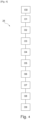
- the method 25 comprises, in an embodiment illustrated by the [ Fig.4 ], an initial operation O0 of unwinding the separator film 3.
- the initial operation O0 is prior to operations O1, O2.
- the initial O0 operation is performed only once during the assembly of the electrodes to form a cell.
- This initial O0 operation allows the separator film to be unrolled without a first electrode on a stacking table.
- the first electrode is deposited on the separator film unrolled during the initial O0 operation.
- the first electrode is for example conveyed with the separator film 3 on one of the faces of the latter.
- This manufacturing unit comprising in particular a control unit equipped with a computer program for implementing the method 25 previously described, advantageously makes it possible to significantly reduce the risk of damage to the separator film 3, thus improving the reliability of the cells thus manufactured and the safety of users.
- the manufacturing unit comprises a mobile carriage.
- the first holding element 8 and the second holding element 10 of the first electrode are mounted on the mobile carriage.
- the first holding element 8 and the second holding element 9 are in the form of gripping means capable of gripping the separator film 3 and a first electrode simultaneously.
- the carriage can then move so as to unroll the separator film and move the first electrode simultaneously.
- the third holding element 11 and the fourth holding element 12 are distinct from the means capable of unwinding the separator film and from the means capable of depositing the second electrode.
- the third holding element 11 and the fourth holding element 12 are in the form of plates.
Landscapes
- Chemical & Material Sciences (AREA)
- Chemical Kinetics & Catalysis (AREA)
- Electrochemistry (AREA)
- General Chemical & Material Sciences (AREA)
- Engineering & Computer Science (AREA)
- Manufacturing & Machinery (AREA)
- Secondary Cells (AREA)
- Cell Separators (AREA)
Claims (14)
- Verfahren (25) zum Herstellen einer Zelle für eine Speicherbatterie, umfassend:- einen ersten Vorgang (01) eines Abrollens einer Trennfolie (3),- einen zweiten Vorgang (O2) eines Aufbringens einer ersten Elektrode (1) auf die Trennfolie (3),- einen dritten Vorgang (O3) eines Haltens einer ersten Seitenkante (4) und einer ersten Längskante (6) der ersten Elektrode (1) mittels eines ersten Halteelements (8) und einer zweiten Seitenkante (5), die der ersten Seitenkante (4) entgegengesetzt ist, und der ersten Längskante (6) der ersten Elektrode (1) mittels eines zweiten Halteelements (10) auf der Trennfolie (3),- einen vierten Vorgang (O4) des Abrollens der Trennfolie (3) zum Bedecken der ersten Elektrode (1),- einen fünften Vorgang (O5) des Aufbringens einer zweiten Elektrode (2) mit entgegengesetzter Polarität zu der ersten Elektrode (1) auf die Trennfolie (3), wobei die zweite Elektrode (2) im Wesentlichen gegenüber der ersten Elektrode (1) angeordnet ist,- einen sechsten Vorgang (O6) des Haltens einer dritten Seitenkante (18) und einer dritten Längskante (20) der zweiten Elektrode (2) mittels eines dritten Halteelements (11) und einer vierten Seitenkante (19) und der dritten Längskante (20) der zweiten Elektrode (2) mittels eines vierten Halteelements (12) auf der Trennfolie (3),- einen siebten Vorgang (O7) des Abrollens der Trennfolie (3) zum Bedecken der zweiten Elektrode (2),- einen achten Vorgang (O8) eines Entfernens des ersten Halteelements (8) und des zweiten Halteelements (10),- einen neunten Vorgang (O9) des Entfernens des dritten Halteelements (11) und des vierten Halteelements (12), in welchem Verfahren die Vorgänge eine Vielzahl von Malen wiederholt werden können,in welchem Verfahren der achte Vorgang (O8) des Entfernens nacheinander eine erste seitliche Bewegung (13), bei der das erste Halteelement (8) und das zweite Halteelement (10) eine Bewegung entlang einer ersten Achse (X) parallel zu der ersten und der zweiten seitlichen Kante (4, 5) ausführen, und eine erste Wegbewegung (14) umfasst, bei der sich das erste und das zweite Halteelement (8, 10) von der ersten Elektrode (1) wegbewegen, oderder achte Vorgang (O8) des Entfernens gleichzeitig eine erste seitliche Bewegung (13), bei der das erste Halteelement (8) und das zweite Halteelement (10) eine Bewegung entlang einer ersten Achse (X) parallel zu der ersten und der zweiten seitlichen Kante (4, 5) ausführen, und eine erste Wegbewegung (14) umfasst, bei der sich das erste und das zweite Halteelement (8, 10) von der ersten Elektrode (1) wegbewegen.
- Verfahren (25) nach Anspruch 1, wobei die erste Wegbewegung (14) entlang einer zweiten Achse (Y) senkrecht zu der ersten Achse (X) vorgenommen wird, wobei die zweite Achse (Y) parallel zu der ersten und der zweiten Längskante (6, 7) der ersten (1) Elektrode ist, wobei die Längskanten (6, 7) im Wesentlichen senkrecht zu der ersten und der zweiten Seitenkante (4, 5) sind.
- Verfahren (25) nach einem der vorstehenden Ansprüche, wobei das erste Halteelement (8) und das zweite Halteelement (10) jeweils mit der ersten Elektrode (1) und der Trennfolie (3) in Kontakt kommen, sodass ein Abschnitt des ersten und des zweiten Halteelements (8, 10) mit der ersten Elektrode (1) in Kontakt steht und ein anderer Abschnitt des ersten und des zweiten Halteelements (8, 10) mit der Trennfolie (3) in Kontakt steht, die sich unter der ersten Elektrode (1) befindet, in welchem Verfahren (25) die Trennfolie (3) um das erste und das zweite Halteelement (8, 10) herum gefaltet wird, indem eine erste Faltlinie (16) definiert wird, die sich entlang der zweiten Achse (Y) erstreckt.
- Verfahren (25) nach Anspruch 3, wobei sich während der ersten seitlichen Bewegung (13) das erste Halteelement (8) und das zweite Halteelement (10) entlang der ersten Achse (X) von der ersten Faltlinie (16) in Richtung der zweiten Längskante (7) verschieben.
- Verfahren (25) nach einem der vorstehenden Ansprüche, wobei der neunte Vorgang (O9) des Entfernens nacheinander eine zweite seitliche Bewegung (23), bei der sich das dritte Halteelement (11) und das vierte Halteelement (12) entlang der ersten Achse (X) bewegen, und eine zweite Wegbewegung (24) umfasst, bei der sich das dritte und das vierte Halteelement (11, 12) von der zweiten Elektrode (2) wegbewegen,
oder
der neunte Vorgang (O9) des Entfernens gleichzeitig eine zweite seitliche Bewegung (23), bei der sich das dritte Halteelement (11) und das vierte Halteelement (12) entlang der ersten Achse (X) bewegen, und eine zweite Wegbewegung (24) umfasst, bei der sich das dritte und das vierte Halteelement (11, 12) von der zweiten Elektrode (2) wegbewegen. - Verfahren (25) nach Anspruch 5, wobei die zweite (24) Wegbewegung entlang einer zweiten Achse (Y) senkrecht zu der ersten Achse (X) vorgenommen wird, wobei die zweite Achse (Y) parallel zu der dritten und der vierten Längskante (20, 21) der zweiten Elektrode (2) ist und wobei die dritte und die vierte Längskante (20, 21) im Wesentlichen senkrecht zu der dritten und der vierten Seitenkante (18, 19) sind.
- Verfahren (25) nach einem der Ansprüche 5 oder 6, wobei das dritte Halteelement (11) und das vierte Halteelement (12) jeweils mit der dritten Seitenkante (18) und der vierten Seitenkante (19) in Kontakt kommen, sodass ein Abschnitt des dritten und des vierten Halteelements (11, 12) mit der zweiten Elektrode (2) in Kontakt steht und ein anderer Abschnitt des dritten und des vierten Halteelements (11, 12) mit der Trennfolie (3) in Kontakt steht, die sich unter der zweiten Elektrode (2) befindet, in welchem Verfahren (25) die Trennfolie (3) um das dritte und das vierte Halteelement (11, 12) herum gefaltet wird, indem eine zweite Faltlinie (17) definiert wird, die sich entlang der zweiten Achse (Y) erstreckt.
- Verfahren (25) nach Anspruch 7, wobei sich während der zweiten seitlichen Bewegung (23) das dritte Halteelement (11) und das vierte Halteelement (12) entlang der ersten Achse (X) von der zweiten Faltlinie (17) in Richtung der vierten Längskante (21) verschieben.
- Verfahren (25) nach einem der vorstehenden Ansprüche, wobei der Vorgang (01) des Abrollens und der Vorgang (O2) des Aufbringens der ersten Elektrode gleichzeitig vorgenommen werden.
- Verfahren (25) nach Anspruch 9, wobei dies einen anfänglichen Vorgang (O0) des Abrollens der Trennfolie (3) vor dem Vorgang (01) des Abrollens und dem Vorgang (O2) des Aufbringens der ersten Elektrode umfasst.
- Verfahren (25) nach Anspruch 10, wobei der anfängliche Vorgang (O0) nur einmal während des Zusammenbaus der Elektroden zum Ausbilden der Zelle ausgeführt wird.
- Herstellungseinheit, umfassend:- Mittel, die geeignet sind, um eine Trennfolie (3) abzurollen,- Mittel, die geeignet sind, um Elektroden (1, 2) auf die Trennfolie (3) aufzubringen,- ein erstes Halteelement (8), ein zweites Halteelement (10), ein drittes Halteelement (11) und ein viertes Halteelement (12),- eine Steuereinheit, umfassend ein Computerprogramm, das geeignet ist, um ein Verfahren (25) nach einem der Ansprüche 1 bis 11 zu implementieren.
- Herstellungseinheit nach Anspruch 12, wobei diese einen bewegbaren Wagen umfasst, auf dem das erste Halteelement (8) und das zweite Halteelement (10) der ersten Elektrode montiert sind, wobei die Halteelemente (8, 9) Greifmittel sind, die geeignet sind, um die Trennfolie (3) und eine erste Elektrode (1) gleichzeitig zu packen.
- Herstellungseinheit nach einem der Ansprüche 12 und 13, wobei das dritte Halteelement (11) und das vierte Halteelement (12) von den Mitteln, die geeignet sind, um die Trennfolie abzurollen, und von den Mitteln, die geeignet sind, um eine zweite Elektrode (2) aufzubringen, verschieden sind.
Applications Claiming Priority (2)
| Application Number | Priority Date | Filing Date | Title |
|---|---|---|---|
| FR2304108A FR3148118B1 (fr) | 2023-04-24 | 2023-04-24 | Procédé et unité de fabrication d’une cellule pour batterie électrique |
| PCT/IB2024/054007 WO2024224315A1 (fr) | 2023-04-24 | 2024-04-24 | Procédé et unité de fabrication d'une cellule pour batterie électrique |
Publications (3)
| Publication Number | Publication Date |
|---|---|
| EP4476779A1 EP4476779A1 (de) | 2024-12-18 |
| EP4476779C0 EP4476779C0 (de) | 2025-05-07 |
| EP4476779B1 true EP4476779B1 (de) | 2025-05-07 |
Family
ID=87136142
Family Applications (1)
| Application Number | Title | Priority Date | Filing Date |
|---|---|---|---|
| EP24725257.0A Active EP4476779B1 (de) | 2023-04-24 | 2024-04-24 | Verfahren und einheit zur herstellung einer zelle für eine elektrische batterie |
Country Status (8)
| Country | Link |
|---|---|
| EP (1) | EP4476779B1 (de) |
| KR (1) | KR20250174092A (de) |
| CN (1) | CN121359242A (de) |
| ES (1) | ES3034489T3 (de) |
| FR (1) | FR3148118B1 (de) |
| HU (1) | HUE071627T2 (de) |
| PL (1) | PL4476779T3 (de) |
| WO (1) | WO2024224315A1 (de) |
Family Cites Families (4)
| Publication number | Priority date | Publication date | Assignee | Title |
|---|---|---|---|---|
| EP2149927B1 (de) * | 2007-05-02 | 2016-08-17 | Enax, Inc. | Stapelungseinrichtung zum stapeln einer kontinuierlichen trennanordnung und folienelektrode |
| KR101020186B1 (ko) * | 2009-06-30 | 2011-03-07 | 주식회사 코캄 | 리튬 이차 전지 제조장치 |
| JP6619902B1 (ja) * | 2019-05-23 | 2019-12-11 | 株式会社日立パワーソリューションズ | 積層装置 |
| JP7549475B2 (ja) * | 2020-07-14 | 2024-09-11 | 株式会社京都製作所 | 積層セルの製造装置 |
-
2023
- 2023-04-24 FR FR2304108A patent/FR3148118B1/fr active Active
-
2024
- 2024-04-24 ES ES24725257T patent/ES3034489T3/es active Active
- 2024-04-24 KR KR1020257039271A patent/KR20250174092A/ko active Pending
- 2024-04-24 CN CN202480027936.5A patent/CN121359242A/zh active Pending
- 2024-04-24 EP EP24725257.0A patent/EP4476779B1/de active Active
- 2024-04-24 PL PL24725257.0T patent/PL4476779T3/pl unknown
- 2024-04-24 WO PCT/IB2024/054007 patent/WO2024224315A1/fr active Pending
- 2024-04-24 HU HUE24725257A patent/HUE071627T2/hu unknown
Also Published As
| Publication number | Publication date |
|---|---|
| FR3148118A1 (fr) | 2024-10-25 |
| HUE071627T2 (hu) | 2025-09-28 |
| EP4476779A1 (de) | 2024-12-18 |
| CN121359242A (zh) | 2026-01-16 |
| PL4476779T3 (pl) | 2025-06-30 |
| EP4476779C0 (de) | 2025-05-07 |
| FR3148118B1 (fr) | 2025-03-14 |
| ES3034489T3 (en) | 2025-08-19 |
| WO2024224315A1 (fr) | 2024-10-31 |
| KR20250174092A (ko) | 2025-12-11 |
Similar Documents
| Publication | Publication Date | Title |
|---|---|---|
| EP3118920B1 (de) | Selbsttragende dünnschicht-batterie, und herstellungsverfahren einer solchen batterie | |
| EP0658946B1 (de) | Elektrodeplatte mit schaumförmigem Träger für elektrochemische Generatoren und Verfahren zur ihrer Herstellung | |
| EP2715857B1 (de) | Halbautomatisches verfahren zur herstellung einer elektrochemischen li-ionenbatterien | |
| EP1810355B1 (de) | Batteriemodul mit einem energiespeicherelement, bei dem der kontakt durch gegenseitige schichtanspannung aktiviert wird | |
| KR20210126842A (ko) | 불량 전극 자동 제거 장치 및 불량 전극 자동 제거 방법 | |
| EP1202299B1 (de) | Aus übereinander gewickelten Bändern bestehende Vorrichtung zur elektrischen Energiespeicherung und Herstellungsverfahren | |
| EP4476779B1 (de) | Verfahren und einheit zur herstellung einer zelle für eine elektrische batterie | |
| EP4156391A1 (de) | Busbar für ein batteriemodul oder ein stapelbatteriepack für flexible batterien zur elektrischen verbindung mindestens eines akkumulators des moduls oder pakets, verfahren zur herstellung eines batteriemoduls oder eines batteriepacks | |
| FR2956780A1 (fr) | Ensemble de contacts electriques a sertir, procede de conditionnement, procede de sertissage et pince de sertissage correspondants | |
| EP4537420B1 (de) | Zelle für eine elektrische batterie und verfahren zur herstellung davon | |
| EP1581978B1 (de) | Endverbindung der schichten aufgewickelter lithium-polymer-batterie | |
| EP4393049B1 (de) | Verfahren und anordnung zur montage von leitenden haarnadelwicklungen für eine elektrische drehmaschine | |
| EP4393051B1 (de) | Verfahren und anordnung zur montage leitfähiger stifte für eine elektrische drehmaschine | |
| FR3157674A1 (fr) | Procédé et unité de fabrication d’une cellule pour batterie électrique | |
| WO2024121736A1 (fr) | Cellule pour batterie électrique et son procédé de fabrication | |
| EP4695854A1 (de) | Zylindrische zelle für eine elektrische batterie und verfahren zur herstellung davon | |
| FR3156243A1 (fr) | Dispositif de maintien pour maintenir un ensemble destiné à la fabrication d’une cellule de batterie | |
| EP4636876A1 (de) | Zelle mit kompressionsplatten, herstellungsverfahren dafür und batterie damit | |
| FR2826518A1 (fr) | Procede pour creer des equipotentialites sur un cable plat | |
| WO2025003183A1 (fr) | Dispositif d'accueil de cellules électrochimiques pour former un module de batterie | |
| FR3155450A1 (fr) | Dispositif de préhension pour élément de faible épaisseur, système et procédé associés | |
| FR3132659A1 (fr) | Dispositif et procédé d’acheminement automatique de patchs à proximité d’un préhenseur de patch | |
| EP4454047A1 (de) | Elektrochemisches bündel, batterieelement und zugehörige herstellungsverfahren | |
| FR2476391A1 (fr) | Procede de fabrication d'un generateur electrochimique et generateur obtenu par ce procede |
Legal Events
| Date | Code | Title | Description |
|---|---|---|---|
| STAA | Information on the status of an ep patent application or granted ep patent |
Free format text: STATUS: UNKNOWN |
|
| STAA | Information on the status of an ep patent application or granted ep patent |
Free format text: STATUS: THE INTERNATIONAL PUBLICATION HAS BEEN MADE |
|
| PUAI | Public reference made under article 153(3) epc to a published international application that has entered the european phase |
Free format text: ORIGINAL CODE: 0009012 |
|
| STAA | Information on the status of an ep patent application or granted ep patent |
Free format text: STATUS: REQUEST FOR EXAMINATION WAS MADE |
|
| GRAP | Despatch of communication of intention to grant a patent |
Free format text: ORIGINAL CODE: EPIDOSNIGR1 |
|
| STAA | Information on the status of an ep patent application or granted ep patent |
Free format text: STATUS: GRANT OF PATENT IS INTENDED |
|
| 17P | Request for examination filed |
Effective date: 20240909 |
|
| AK | Designated contracting states |
Kind code of ref document: A1 Designated state(s): AL AT BE BG CH CY CZ DE DK EE ES FI FR GB GR HR HU IE IS IT LI LT LU LV MC ME MK MT NL NO PL PT RO RS SE SI SK SM TR |
|
| DAV | Request for validation of the european patent (deleted) | ||
| DAX | Request for extension of the european patent (deleted) | ||
| INTG | Intention to grant announced |
Effective date: 20241203 |
|
| GRAS | Grant fee paid |
Free format text: ORIGINAL CODE: EPIDOSNIGR3 |
|
| GRAA | (expected) grant |
Free format text: ORIGINAL CODE: 0009210 |
|
| STAA | Information on the status of an ep patent application or granted ep patent |
Free format text: STATUS: THE PATENT HAS BEEN GRANTED |
|
| AK | Designated contracting states |
Kind code of ref document: B1 Designated state(s): AL AT BE BG CH CY CZ DE DK EE ES FI FR GB GR HR HU IE IS IT LI LT LU LV MC ME MK MT NL NO PL PT RO RS SE SI SK SM TR |
|
| REG | Reference to a national code |
Ref country code: GB Ref legal event code: FG4D Free format text: NOT ENGLISH |
|
| REG | Reference to a national code |
Ref country code: CH Ref legal event code: EP |
|
| REG | Reference to a national code |
Ref country code: DE Ref legal event code: R096 Ref document number: 602024000115 Country of ref document: DE |
|
| REG | Reference to a national code |
Ref country code: IE Ref legal event code: FG4D Free format text: LANGUAGE OF EP DOCUMENT: FRENCH |
|
| U01 | Request for unitary effect filed |
Effective date: 20250521 |
|
| U07 | Unitary effect registered |
Designated state(s): AT BE BG DE DK EE FI FR IT LT LU LV MT NL PT RO SE SI Effective date: 20250530 |
|
| REG | Reference to a national code |
Ref country code: ES Ref legal event code: FG2A Ref document number: 3034489 Country of ref document: ES Kind code of ref document: T3 Effective date: 20250819 |
|
| REG | Reference to a national code |
Ref country code: SK Ref legal event code: T3 Ref document number: E 46730 Country of ref document: SK |
|
| REG | Reference to a national code |
Ref country code: HU Ref legal event code: AG4A Ref document number: E071627 Country of ref document: HU |
|
| PG25 | Lapsed in a contracting state [announced via postgrant information from national office to epo] |
Ref country code: GR Free format text: LAPSE BECAUSE OF FAILURE TO SUBMIT A TRANSLATION OF THE DESCRIPTION OR TO PAY THE FEE WITHIN THE PRESCRIBED TIME-LIMIT Effective date: 20250808 |
|
| PG25 | Lapsed in a contracting state [announced via postgrant information from national office to epo] |
Ref country code: HR Free format text: LAPSE BECAUSE OF FAILURE TO SUBMIT A TRANSLATION OF THE DESCRIPTION OR TO PAY THE FEE WITHIN THE PRESCRIBED TIME-LIMIT Effective date: 20250507 |
|
| PG25 | Lapsed in a contracting state [announced via postgrant information from national office to epo] |
Ref country code: RS Free format text: LAPSE BECAUSE OF FAILURE TO SUBMIT A TRANSLATION OF THE DESCRIPTION OR TO PAY THE FEE WITHIN THE PRESCRIBED TIME-LIMIT Effective date: 20250807 |
|
| PG25 | Lapsed in a contracting state [announced via postgrant information from national office to epo] |
Ref country code: IS Free format text: LAPSE BECAUSE OF FAILURE TO SUBMIT A TRANSLATION OF THE DESCRIPTION OR TO PAY THE FEE WITHIN THE PRESCRIBED TIME-LIMIT Effective date: 20250907 |
|
| PG25 | Lapsed in a contracting state [announced via postgrant information from national office to epo] |
Ref country code: SM Free format text: LAPSE BECAUSE OF FAILURE TO SUBMIT A TRANSLATION OF THE DESCRIPTION OR TO PAY THE FEE WITHIN THE PRESCRIBED TIME-LIMIT Effective date: 20250507 |