EP4475469A1 - Dekodierungsvorrichtung und -verfahren in einem drahtlosen kommunikationssystem - Google Patents
Dekodierungsvorrichtung und -verfahren in einem drahtlosen kommunikationssystem Download PDFInfo
- Publication number
- EP4475469A1 EP4475469A1 EP23763652.7A EP23763652A EP4475469A1 EP 4475469 A1 EP4475469 A1 EP 4475469A1 EP 23763652 A EP23763652 A EP 23763652A EP 4475469 A1 EP4475469 A1 EP 4475469A1
- Authority
- EP
- European Patent Office
- Prior art keywords
- llr
- llr value
- value
- output
- electronic device
- Prior art date
- Legal status (The legal status is an assumption and is not a legal conclusion. Google has not performed a legal analysis and makes no representation as to the accuracy of the status listed.)
- Pending
Links
Images


Classifications
-
- H—ELECTRICITY
- H04—ELECTRIC COMMUNICATION TECHNIQUE
- H04B—TRANSMISSION
- H04B7/00—Radio transmission systems, i.e. using radiation field
- H04B7/02—Diversity systems; Multi-antenna system, i.e. transmission or reception using multiple antennas
- H04B7/04—Diversity systems; Multi-antenna system, i.e. transmission or reception using multiple antennas using two or more spaced independent antennas
- H04B7/0413—MIMO systems
- H04B7/0417—Feedback systems
-
- H—ELECTRICITY
- H04—ELECTRIC COMMUNICATION TECHNIQUE
- H04B—TRANSMISSION
- H04B1/00—Details of transmission systems, not covered by a single one of groups H04B3/00 - H04B13/00; Details of transmission systems not characterised by the medium used for transmission
- H04B1/69—Spread spectrum techniques
- H04B1/707—Spread spectrum techniques using direct sequence modulation
- H04B1/7097—Interference-related aspects
- H04B1/7103—Interference-related aspects the interference being multiple access interference
- H04B1/7107—Subtractive interference cancellation
-
- H—ELECTRICITY
- H04—ELECTRIC COMMUNICATION TECHNIQUE
- H04B—TRANSMISSION
- H04B7/00—Radio transmission systems, i.e. using radiation field
- H04B7/02—Diversity systems; Multi-antenna system, i.e. transmission or reception using multiple antennas
- H04B7/04—Diversity systems; Multi-antenna system, i.e. transmission or reception using multiple antennas using two or more spaced independent antennas
- H04B7/06—Diversity systems; Multi-antenna system, i.e. transmission or reception using multiple antennas using two or more spaced independent antennas at the transmitting station
- H04B7/0602—Diversity systems; Multi-antenna system, i.e. transmission or reception using multiple antennas using two or more spaced independent antennas at the transmitting station using antenna switching
- H04B7/0608—Antenna selection according to transmission parameters
- H04B7/061—Antenna selection according to transmission parameters using feedback from receiving side
-
- H—ELECTRICITY
- H04—ELECTRIC COMMUNICATION TECHNIQUE
- H04L—TRANSMISSION OF DIGITAL INFORMATION, e.g. TELEGRAPHIC COMMUNICATION
- H04L1/00—Arrangements for detecting or preventing errors in the information received
-
- H—ELECTRICITY
- H04—ELECTRIC COMMUNICATION TECHNIQUE
- H04L—TRANSMISSION OF DIGITAL INFORMATION, e.g. TELEGRAPHIC COMMUNICATION
- H04L1/00—Arrangements for detecting or preventing errors in the information received
- H04L1/004—Arrangements for detecting or preventing errors in the information received by using forward error control
- H04L1/0045—Arrangements at the receiver end
- H04L1/0047—Decoding adapted to other signal detection operation
- H04L1/0048—Decoding adapted to other signal detection operation in conjunction with detection of multiuser or interfering signals, e.g. iteration between CDMA or MIMO detector and FEC decoder
-
- H—ELECTRICITY
- H04—ELECTRIC COMMUNICATION TECHNIQUE
- H04L—TRANSMISSION OF DIGITAL INFORMATION, e.g. TELEGRAPHIC COMMUNICATION
- H04L1/00—Arrangements for detecting or preventing errors in the information received
- H04L1/004—Arrangements for detecting or preventing errors in the information received by using forward error control
- H04L1/0045—Arrangements at the receiver end
- H04L1/0047—Decoding adapted to other signal detection operation
- H04L1/005—Iterative decoding, including iteration between signal detection and decoding operation
-
- H—ELECTRICITY
- H04—ELECTRIC COMMUNICATION TECHNIQUE
- H04L—TRANSMISSION OF DIGITAL INFORMATION, e.g. TELEGRAPHIC COMMUNICATION
- H04L1/00—Arrangements for detecting or preventing errors in the information received
- H04L1/02—Arrangements for detecting or preventing errors in the information received by diversity reception
- H04L1/06—Arrangements for detecting or preventing errors in the information received by diversity reception using space diversity
-
- H—ELECTRICITY
- H04—ELECTRIC COMMUNICATION TECHNIQUE
- H04L—TRANSMISSION OF DIGITAL INFORMATION, e.g. TELEGRAPHIC COMMUNICATION
- H04L25/00—Baseband systems
- H04L25/02—Details ; arrangements for supplying electrical power along data transmission lines
- H04L25/03—Shaping networks in transmitter or receiver, e.g. adaptive shaping networks
- H04L25/03006—Arrangements for removing intersymbol interference
- H04L25/03178—Arrangements involving sequence estimation techniques
- H04L25/03248—Arrangements for operating in conjunction with other apparatus
- H04L25/03286—Arrangements for operating in conjunction with other apparatus with channel-decoding circuitry
-
- H—ELECTRICITY
- H04—ELECTRIC COMMUNICATION TECHNIQUE
- H04L—TRANSMISSION OF DIGITAL INFORMATION, e.g. TELEGRAPHIC COMMUNICATION
- H04L25/00—Baseband systems
- H04L25/02—Details ; arrangements for supplying electrical power along data transmission lines
- H04L25/03—Shaping networks in transmitter or receiver, e.g. adaptive shaping networks
- H04L25/03006—Arrangements for removing intersymbol interference
- H04L25/03178—Arrangements involving sequence estimation techniques
- H04L25/03312—Arrangements specific to the provision of output signals
- H04L25/03318—Provision of soft decisions
Definitions
- the disclosure relates to a decoding device and method for correcting errors in data transmitted in a wireless communication system. More particularly, the disclosure relates to a device and method for channel decoding in a wireless communication system using multiple-input multiple-output (MIMO) system and channel coding code by connecting.
- MIMO multiple-input multiple-output
- a data error may occur in a receiver due to noise existing in a communication channel.
- a coding method designed to correct errors, generated by a communication channel, in a receiver is called error correcting codes (ECC).
- ECC error correcting codes
- coding for correcting errors occurring on a communication path between a transmitter and a receiver that is a communication channel is also called channel coding.
- a data bit to be transmitted is transmitted by adding an additional bit, and the receiver utilizes the additional bit to perform a decoding operation of correcting an error included in the transmitted the data bit.
- error correcting codes include convolutional coding, turbo coding, low-density parity-check coding (LDPC coding), and polar coding methods, and especially turbo coding and LDPC coding are excellent coding having performance close to the theoretical channel capacity, and have been adopted as core technologies in wireless communication standards such as long term evolution (LTE) and 5 th generation (5G).
- MIMO multiple-input multiple-output
- LTE and 5G wireless communication systems
- FD-MIMO full dimensional MIMO
- 6G 6 th generation
- LTE long term evolution
- 5G 5 th generation
- the receiver that receives a signal transmitted according to the above-described channel coding method goes through a procedure of detecting an error by decoding the received signal.
- the turbo coding used in LTE and the LDPC coding used in 5G configure a transmission bit by adding a parity bit, which is an additional bit, to an information bit.
- the MIMO detector calculates a channel log likelihood ratio (LLR) for the transmission bits and provides it to the channel decoder.
- the channel decoder performs channel decoding using the input channel LLR.
- an iterative detection and decoding (IDD) technique is widely used as a representative channel decoding technique.
- the channel decoder provides the decoded information to the MIMO detector, and then performs decoding using the information provided by the MIMO detector.
- the information provided between the channel decoder and the MIMO detector is LLR, it may be highly large data. Therefore, in actual implementation, due to an increase in complexity, processing speed, and limitation of memory capacity, it is implemented in a fixed-point method. Therefore, in the fixed-point method, a range constraint occurs depending on the amount of quantization of information. In case that the quantization level is increased, the loss of performance is decreased, but the complexity is increased. Conversely, in case that the quantization level is lowered, the complexity is decreased but the loss of performance is increased. In other words, there is a trade-off relationship between them. Therefore, it may be an especially important factor to determine an optimal quantization level in a fixed-point of a certain size or more according to the quantization level.
- the present disclosure provides a channel decoder device and method for preventing decoding performance degradation in a wireless communication system.
- the present disclosure provides a channel decoder device and method capable of maintaining higher decoding performance without increasing the complexity of the channel decoder in a wireless communication system.
- the present disclosure provides a device and method for increasing the soft-output performance of the channel decoder when a receiver using successive interference cancelling (SIC) is used in a communication system using the multiple-input multiple-output (MIMO) method.
- SIC successive interference cancelling
- MIMO multiple-input multiple-output
- the present disclosure provides a channel decoding device and method for reducing complexity when a receiver using successive interference cancelling (SIC) is used in a communication system using the MIMO method.
- SIC successive interference cancelling
- an electronic device in a wireless communication system comprises a multiple-input multiple-output (MIMO) detector configured to generate an output log likelihood ratio (LLR) value based on signals received from a plurality of antennas and a feedback LLR value.
- MIMO multiple-input multiple-output
- the electronic device comprises a channel decoder configured to output a channel decoded LLR value through channel decoding and a second operation by using the LLR value of the MIMO detector.
- the electronic device comprises a feedback compensator configured to generate the feedback LLR value so that the channel decoded LLR value is between an upper threshold and a lower threshold determined based on a bit width of an LLR of the electronic device.
- an electronic device in a wireless communication system comprises a multiple-input multiple-output (MIMO) detector that generates an output log likelihood ratio (LLR) value by using signals received from a plurality of antennas and a feedback LLR value.
- the electronic device comprises a channel decoder.
- the channel decoder comprises a channel decoder core configured to perform channel decoding based on the output LLR value and to output a second LLR value.
- the channel decoder comprises an initial extrinsic LLR calculator configured to generate a decoded LLR value by performing a second operation on the second LLR value.
- the channel decoder comprises an extrinsic LLR range calculator configured to determine an upper threshold and a lower threshold based on a threshold determined based on a bit width of the LLR of the electronic device.
- the channel decoder comprises an extrinsic LLR generator configured to generate the feedback LLR value so that the decoded LLR value is between the upper threshold and the lower threshold received from the extrinsic LLR range calculator.
- a method performed by an electronic device in a wireless communication system comprises generating an output log likelihood ratio (LLR) value based on signals received from a plurality of antennas and a feedback LLR value.
- the method comprises outputting a second LLR value by performing channel decoding based on the output LLR value.
- the method comprises generating a decoded LLR value by performing a second operation on the second LLR value.
- the method comprises determining an upper threshold and a lower threshold based on a threshold determined based on a bit width of the LLR of the electronic device.
- the method comprises generating the feedback LLR value so that the decoded LLR value is between the upper threshold and the lower threshold.
- an iterative detection and decoding (IDD) device in a receiving device of a wireless communication system by using multiple-input multiple-output (MIMO) and a channel code by connecting includes a MIMO detector that generates an output log likelihood ratio (LLR) value by using signals received from a plurality of antennas and a feedback LLR value, a channel decoder for outputting a channel decoded LLR value through channel decoding and a second operation by using the LLR value of the MIMO detector, and a feedback compensator for generating the feedback LLR value so that the channel decoded LLR value is within the range of an upper threshold and a lower threshold determined based on a bit width of an LLR used by the receiving device.
- LLR log likelihood ratio
- an iterative detection and decoding (IDD) device in a receiving device of a wireless communication system by using multiple-input multiple-output (MIMO) and a channel code by connecting is provided.
- the IDD device includes a MIMO detector that generates an output log likelihood ratio (LLR) value by using signals received from a plurality of antennas and a feedback LLR value, and a channel decoder.
- LLR log likelihood ratio
- the channel decoder includes a channel decoder core that performs channel decoding by using the output LLR value and outputs a second LLR value, an initial extrinsic LLR calculator for generating the decoded LLR value by performing the second operation on the second LLR value, an extrinsic LLR range calculator for determining the upper threshold and the lower threshold by using a threshold determined based on the bit width of the LLR used by the receiving device, and an extrinsic LLR generator for generating the feedback LLR value so that the decoded LLR value is within the range of the upper and lower thresholds received from the extrinsic LLR range calculator.
- an iterative detection and decoding (IDD) method in a receiving device of a wireless communication system by using multiple-input multiple-output (MIMO) and a channel code by connecting includes generating an output log likelihood ratio (LLR) value by using signals received from a plurality of antennas and a feedback LLR value, outputting a second LLR value by performing channel decoding by using the output LLR value, generating the decoded LLR value by performing a second operation on the second LLR value, determining the upper threshold and the lower threshold by using a threshold determined based on a bit width of the LLR used by the receiving device, and generating the feedback LLR value so that the decoded LLR value is within the range of the upper threshold and the lower threshold.
- LLR log likelihood ratio
- the decoding device In case that the decoding device according to the disclosure is used, it can be possible to generate soft-output capable of improving the performance of the sequential interference receiver of the coded MIMO system without significantly increasing the complexity of the channel decoder.
- the method presented in the disclosure can be configured and applied independently of the existing channel decoder, the performance of the existing receiver can be improved without redesigning and implementing the channel decoder having a complicated implementation.
- FIG. 1 is a block diagram illustrating an electronic device 101 in a network environment 100 according to an embodiment of the disclosure.
- the electronic device 101 in the network environment 100 may communicate with an electronic device 102 via a first network 198 (e.g., a short-range wireless communication network), or at least one of an electronic device 104 or a server 108 via a second network 199 (e.g., a long-range wireless communication network).
- the electronic device 101 may communicate with the electronic device 104 via the server 108.
- the electronic device 101 may include a processor 120, memory 130, an input module 150, a sound output module 155, a display module 160, an audio module 170, a sensor module 176, an interface 177, a connecting terminal 178, a haptic module 179, a camera module 180, a power management module 188, a battery 189, a communication module 190, a subscriber identification module (SIM) 196, or an antenna module 197.
- at least one of the components e.g., the connecting terminal 178) may be omitted from the electronic device 101, or one or more other components may be added in the electronic device 101.
- some of the components e.g., the sensor module 176, the camera module 180, or the antenna module 197) may be implemented as a single component (e.g., the display module 160).
- the processor 120 may execute, for example, software (e.g., a program 140) to control at least one other component (e.g., a hardware or software component) of the electronic device 101 coupled with the processor 120, and may perform various data processing or computation. According to one embodiment, as at least part of the data processing or computation, the processor 120 may store a command or data received from another component (e.g., the sensor module 176 or the communication module 190) in volatile memory 132, process the command or the data stored in the volatile memory 132, and store resulting data in non-volatile memory 134.
- software e.g., a program 140
- the processor 120 may store a command or data received from another component (e.g., the sensor module 176 or the communication module 190) in volatile memory 132, process the command or the data stored in the volatile memory 132, and store resulting data in non-volatile memory 134.
- the processor 120 may include a main processor 121 (e.g., a central processing unit (CPU) or an application processor (AP)), or an auxiliary processor 123 (e.g., a graphics processing unit (GPU), a neural processing unit (NPU), an image signal processor (ISP), a sensor hub processor, or a communication processor (CP)) that is operable independently from, or in conjunction with, the main processor 121.
- a main processor 121 e.g., a central processing unit (CPU) or an application processor (AP)
- auxiliary processor 123 e.g., a graphics processing unit (GPU), a neural processing unit (NPU), an image signal processor (ISP), a sensor hub processor, or a communication processor (CP)
- the main processor 121 may be adapted to consume less power than the main processor 121, or to be specific to a specified function.
- the auxiliary processor 123 may be implemented as separate from, or as part of the main processor 121.
- the auxiliary processor 123 may control at least some of functions or states related to at least one component (e.g., the display module 160, the sensor module 176, or the communication module 190) among the components of the electronic device 101, instead of the main processor 121 while the main processor 121 is in an inactive
- the auxiliary processor 123 e.g., an image signal processor or a communication processor
- the auxiliary processor 123 may be implemented as part of another component (e.g., the camera module 180 or the communication module 190) functionally related to the auxiliary processor 123.
- the auxiliary processor 123 e.g., the neural processing unit
- An artificial intelligence model may be generated by machine learning. Such learning may be performed, e.g., by the electronic device 101 where the artificial intelligence is performed or via a separate server (e.g., the server 108).
- the artificial intelligence model may include a plurality of artificial neural network layers.
- the artificial neural network may be a deep neural network (DNN), a convolutional neural network (CNN), a recurrent neural network (RNN), a restricted boltzmann machine (RBM), a deep belief network (DBN), a bidirectional recurrent deep neural network (BRDNN), deep Q-network or a combination of two or more thereof but is not limited thereto.
- the artificial intelligence model may, additionally or alternatively, include a software structure other than the hardware structure.
- the memory 130 may store various data used by at least one component (e.g., the processor 120 or the sensor module 176) of the electronic device 101.
- the various data may include, for example, software (e.g., the program 140) and input data or output data for a command related thereto.
- the memory 130 may include the volatile memory 132 or the non-volatile memory 134.
- the program 140 may be stored in the memory 130 as software, and may include, for example, an operating system (OS) 142, middleware 144, or an application 146.
- OS operating system
- middleware middleware
- application application
- the input module 150 may receive a command or data to be used by another component (e.g., the processor 120) of the electronic device 101, from the outside (e.g., a user) of the electronic device 101.
- the input module 150 may include, for example, a microphone, a mouse, a keyboard, a key (e.g., a button), or a digital pen (e.g., a stylus pen).
- the sound output module 155 may output sound signals to the outside of the electronic device 101.
- the sound output module 155 may include, for example, a speaker or a receiver.
- the speaker may be used for general purposes, such as playing multimedia or playing record.
- the receiver may be used for receiving incoming calls. According to an embodiment, the receiver may be implemented as separate from, or as part of the speaker.
- the display module 160 may visually provide information to the outside (e.g., a user) of the electronic device 101.
- the display module 160 may include, for example, a display, a hologram device, or a projector and control circuitry to control a corresponding one of the display, hologram device, and projector.
- the display module 160 may include a touch sensor adapted to detect a touch, or a pressure sensor adapted to measure the intensity of force incurred by the touch.
- the audio module 170 may convert a sound into an electrical signal and vice versa. According to an embodiment, the audio module 170 may obtain the sound via the input module 150, or output the sound via the sound output module 155 or a headphone of an external electronic device (e.g., an electronic device 102) directly (e.g., wiredly) or wirelessly coupled with the electronic device 101.
- an external electronic device e.g., an electronic device 102
- directly e.g., wiredly
- wirelessly e.g., wirelessly
- the sensor module 176 may detect an operational state (e.g., power or temperature) of the electronic device 101 or an environmental state (e.g., a state of a user) external to the electronic device 101, and then generate an electrical signal or data value corresponding to the detected state.
- the sensor module 176 may include, for example, a gesture sensor, a gyro sensor, an atmospheric pressure sensor, a magnetic sensor, an acceleration sensor, a grip sensor, a proximity sensor, a color sensor, an infrared (IR) sensor, a biometric sensor, a temperature sensor, a humidity sensor, or an illuminance sensor.
- the interface 177 may support one or more specified protocols to be used for the electronic device 101 to be coupled with the external electronic device (e.g., the electronic device 102) directly (e.g., wiredly) or wirelessly.
- the interface 177 may include, for example, a high definition multimedia interface (HDMI), a universal serial bus (USB) interface, a secure digital (SD) card interface, or an audio interface.
- HDMI high definition multimedia interface
- USB universal serial bus
- SD secure digital
- a connecting terminal 178 may include a connector via which the electronic device 101 may be physically connected with the external electronic device (e.g., the electronic device 102).
- the connecting terminal 178 may include, for example, an HDMI connector, a USB connector, an SD card connector, or an audio connector (e.g., a headphone connector).
- the haptic module 179 may convert an electrical signal into a mechanical stimulus (e.g., a vibration or a movement) or electrical stimulus which may be recognized by a user via his tactile sensation or kinesthetic sensation.
- the haptic module 179 may include, for example, a motor, a piezoelectric element, or an electric stimulator.
- the camera module 180 may capture a still image or moving images.
- the camera module 180 may include one or more lenses, image sensors, image signal processors, or flashes.
- the power management module 188 may manage power supplied to the electronic device 101.
- the power management module 188 may be implemented as at least part of, for example, a power management integrated circuit (PMIC).
- PMIC power management integrated circuit
- the battery 189 may supply power to at least one component of the electronic device 101.
- the battery 189 may include, for example, a primary cell which is not rechargeable, a secondary cell which is rechargeable, or a fuel cell.
- the communication module 190 may support establishing a direct (e.g., wired) communication channel or a wireless communication channel between the electronic device 101 and the external electronic device (e.g., the electronic device 102, the electronic device 104, or the server 108) and performing communication via the established communication channel.
- the communication module 190 may include one or more communication processors that are operable independently from the processor 120 (e.g., the application processor (AP)) and supports a direct (e.g., wired) communication or a wireless communication.
- AP application processor
- the communication module 190 may include a wireless communication module 192 (e.g., a cellular communication module, a short-range wireless communication module, or a global navigation satellite system (GNSS) communication module) or a wired communication module 194 (e.g., a local area network (LAN) communication module or a power line communication (PLC) module).
- a wireless communication module 192 e.g., a cellular communication module, a short-range wireless communication module, or a global navigation satellite system (GNSS) communication module
- GNSS global navigation satellite system
- wired communication module 194 e.g., a local area network (LAN) communication module or a power line communication (PLC) module.
- LAN local area network
- PLC power line communication
- a corresponding one of these communication modules may communicate with the external electronic device via the first network 198 (e.g., a short-range communication network, such as Bluetooth TM , wireless-fidelity (Wi-Fi) direct, or infrared data association (IrDA)) or the second network 199 (e.g., a long-range communication network, such as a legacy cellular network, a 5G network, a next-generation communication network, the Internet, or a computer network (e.g., LAN or wide area network (WAN))).
- first network 198 e.g., a short-range communication network, such as Bluetooth TM , wireless-fidelity (Wi-Fi) direct, or infrared data association (IrDA)
- the second network 199 e.g., a long-range communication network, such as a legacy cellular network, a 5G network, a next-generation communication network, the Internet, or a computer network (e.g., LAN or wide area network (WAN)).
- the wireless communication module 192 may identify and authenticate the electronic device 101 in a communication network, such as the first network 198 or the second network 199, using subscriber information (e.g., international mobile subscriber identity (IMSI)) stored in the subscriber identification module 196.
- subscriber information e.g., international mobile subscriber identity (IMSI)
- the wireless communication module 192 may support a 5G network, after a 4 th generation (4G) network, and next-generation communication technology, e.g., new radio (NR) access technology.
- the NR access technology may support enhanced mobile broadband (eMBB), massive machine type communications (mMTC), or ultra-reliable and low-latency communications (URLLC).
- eMBB enhanced mobile broadband
- mMTC massive machine type communications
- URLLC ultra-reliable and low-latency communications
- the wireless communication module 192 may support a high-frequency band (e.g., the mmWave band) to achieve, e.g., a high data transmission rate.
- the wireless communication module 192 may support various technologies for securing performance on a high-frequency band, such as, e.g., beamforming, massive multiple-input and multiple-output (massive MIMO), full dimensional MIMO (FD-MIMO), array antenna, analog beam-forming, or large scale antenna.
- the wireless communication module 192 may support various requirements specified in the electronic device 101, an external electronic device (e.g., the electronic device 104), or a network system (e.g., the second network 199).
- the wireless communication module 192 may support a peak data rate (e.g., 20Gbps or more) for implementing eMBB, loss coverage (e.g., 164dB or less) for implementing mMTC, or user plane (U-plane) latency (e.g., 0.5ms or less for each of downlink (DL) and uplink (UL), or a round trip of 1ms or less) for implementing URLLC.
- a peak data rate e.g., 20Gbps or more
- loss coverage e.g., 164dB or less
- U-plane user plane latency
- the antenna module 197 may transmit or receive a signal or power to or from the outside (e.g., the external electronic device) of the electronic device 101.
- the antenna module 197 may include an antenna including a radiating element composed of a conductive material or a conductive pattern formed in or on a substrate (e.g., a printed circuit board (PCB)).
- the antenna module 197 may include a plurality of antennas (e.g., array antennas). In such a case, at least one antenna appropriate for a communication scheme used in the communication network, such as the first network 198 or the second network 199, may be selected, for example, by the communication module 190 (e.g., the wireless communication module 192) from the plurality of antennas.
- the signal or the power may then be transmitted or received between the communication module 190 and the external electronic device via the selected at least one antenna.
- another component e.g., a radio frequency integrated circuit (RFIC)
- RFIC radio frequency integrated circuit
- the antenna module 197 may form a mmWave antenna module.
- the mmWave antenna module may include a printed circuit board, an RFIC disposed on a first surface (e.g., the bottom surface) of the printed circuit board, or adjacent to the first surface and capable of supporting a designated high-frequency band (e.g., the millimeter wave (mmWave) band), and a plurality of antennas (e.g., array antennas) disposed on a second surface (e.g., the top or a side surface) of the printed circuit board, or adjacent to the second surface and capable of transmitting or receiving signals of the designated high-frequency band.
- a designated high-frequency band e.g., the millimeter wave (mmWave) band
- a plurality of antennas e.g., array antennas
- At least some of the above-described components may be coupled mutually and communicate signals (e.g., commands or data) therebetween via an inter-peripheral communication scheme (e.g., a bus, general purpose input and output (GPIO), serial peripheral interface (SPI), or mobile industry processor interface (MIPI)).
- an inter-peripheral communication scheme e.g., a bus, general purpose input and output (GPIO), serial peripheral interface (SPI), or mobile industry processor interface (MIPI)
- commands or data may be transmitted or received between the electronic device 101 and the external electronic device 104 via the server 108 coupled with the second network 199.
- Each of the electronic devices 102 or 104 may be a device of a same type as, or a different type, from the electronic device 101.
- all or some of operations to be executed at the electronic device 101 may be executed at one or more of the external electronic devices 102, 104, or 108. For example, if the electronic device 101 should perform a function or a service automatically, or in response to a request from a user or another device, the electronic device 101, instead of, or in addition to, executing the function or the service, may request the one or more external electronic devices to perform at least part of the function or the service.
- the one or more external electronic devices receiving the request may perform the at least part of the function or the service requested, or an additional function or an additional service related to the request, and transfer an outcome of the performing to the electronic device 101.
- the electronic device 101 may provide the outcome, with or without further processing of the outcome, as at least part of a reply to the request.
- a cloud computing, distributed computing, mobile edge computing (MEC), or client-server computing technology may be used, for example.
- the electronic device 101 may provide ultra low-latency services using, e.g., distributed computing or mobile edge computing.
- the external electronic device 104 may include an internet-of things (IoT) device.
- the server 108 may be an intelligent server using machine learning and/or a neural network.
- the external electronic device 104 or the server 108 may be included in the second network 199.
- the electronic device 101 may be applied to intelligent services (e.g., smart home, smart city, smart car, or healthcare) based on 5G communication technology or IoT-related technology.
- the electronic device may be one of various types of electronic devices.
- the electronic devices may include, for example, a portable communication device (e.g., a smartphone), a computer device, a portable multimedia device, a portable medical device, a camera, a wearable device, or a home appliance. According to an embodiment of the disclosure, the electronic devices are not limited to those described above.
- each of such phrases as “A or B,” “at least one of A and B,” “at least one of A or B,” “A, B, or C,” “at least one of A, B, and C,” and “at least one of A, B, or C,” may include any one of, or all possible combinations of the items enumerated together in a corresponding one of the phrases.
- such terms as “1st” and “2nd,” or “first” and “second” may be used to simply distinguish a corresponding component from another, and does not limit the components in other aspect (e.g., importance or order).
- an element e.g., a first element
- the element may be coupled with the other element directly (e.g., wiredly), wirelessly, or via a third element.
- module may include a unit implemented in hardware, software, or firmware, and may interchangeably be used with other terms, for example, “logic,” “logic block,” “part,” or “circuitry.”
- a module may be a single integral component, or a minimum unit or part thereof, adapted to perform one or more functions.
- the module may be implemented in a form of an application-specific integrated circuit (ASIC).
- ASIC application-specific integrated circuit
- Various embodiments as set forth herein may be implemented as software (e.g., the program 140) including one or more instructions that are stored in a storage medium (e.g., internal memory 136 or external memory 138) that is readable by a machine (e.g., the electronic device 101).
- a processor e.g., the processor 120
- the machine e.g., the electronic device 101
- the one or more instructions may include a code generated by a complier or a code executable by an interpreter.
- the machine-readable storage medium may be provided in the form of a non-transitory storage medium.
- non-transitory simply means that the storage medium is a tangible device, and does not include a signal (e.g., an electromagnetic wave), but this term does not differentiate between where data is semi-permanently stored in the storage medium and where the data is temporarily stored in the storage medium.
- a method may be included and provided in a computer program product.
- the computer program product may be traded as a product between a seller and a buyer.
- the computer program product may be distributed in the form of a machine-readable storage medium (e.g., compact disc read only memory (CD-ROM)), or be distributed (e.g., downloaded or uploaded) online via an application store (e.g., PlayStore TM ), or between two user devices (e.g., smart phones) directly. If distributed online, at least part of the computer program product may be temporarily generated or at least temporarily stored in the machine-readable storage medium, such as memory of the manufacturer's server, a server of the application store, or a relay server.
- CD-ROM compact disc read only memory
- an application store e.g., PlayStore TM
- two user devices e.g., smart phones
- each component e.g., a module or a program of the above-described components may include a single entity or multiple entities, and some of the multiple entities may be separately disposed in different components. According to various embodiments, one or more of the above-described components may be omitted, or one or more other components may be added. Alternatively or additionally, a plurality of components (e.g., modules or programs) may be integrated into a single component. In such a case, according to various embodiments, the integrated component may still perform one or more functions of each of the plurality of components in the same or similar manner as they are performed by a corresponding one of the plurality of components before the integration.
- operations performed by the module, the program, or another component may be carried out sequentially, in parallel, repeatedly, or heuristically, or one or more of the operations may be executed in a different order or omitted, or one or more other operations may be added.
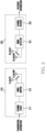
- FIG. 2 is a drawing illustrating a simplified configuration of a transmitter and a receiver of a multiple-input multiple-output (MIMO) system according to an embodiment of the disclosure.
- MIMO multiple-input multiple-output
- the transmitter 210 may be described by assuming a base station of a long term evolution (LTE), fifth generation (5G), and/or sixth generation (6G) system among wireless communication systems, and the receiver 220 may become the electronic device 101 described in FIG. 1 .
- the base station may become the receiver 220.
- the transmitter and receiver of the disclosure are not limited to transmitters and receivers of LTE, 5G, and/or 6G systems.
- D2D device-to-device
- AP access point
- AP access point
- WiFi WiFi
- the transmitter 210 of FIG. 2 may include a channel coder 211 for coding information to be transmitted, a MIMO mapper 212 for mapping the coded signal to be transmitted to a plurality of transmission (Tx) antennas Tx ant#1 and Tx ant#M, and a plurality of transmission antennas Tx ant#1 and Tx ant#M.
- Tx transmission
- the plurality of transmission antennas Tx ant#1 and Tx ant#M may also be used as reception antennas.
- the transmitter 210 may further have a configuration such as a band up converter and a power amplifier for transmitting a signal to a transmission band.
- the transmitter 210 may further include various components such as a base station controller and a scheduler.
- FIG. 2 only the configuration necessary for describing the disclosure is illustrated and described.
- the channel coder 211 of the transmitter 210 may code information to be transmitted in a promised manner with the receiver 220.
- the coding method any one or more methods of the above-described coding methods such as convolutional coding, turbo coding, low-density parity-check coding (LDPC coding), and polar coding method may be used.
- the signal coded by the channel coder 211 may be mapped to be transmitted by the MIMO mapper 212 to a plurality of antennas.
- a mapping method in the MIMO mapper 212 may be mapped in different forms depending on a method required by each system, and in the disclosure, no restrictions are placed on this.
- Signals output from the MIMO mapper 212 may be transmitted through a plurality of transmission antennas Tx ant#1 and Tx ant#M.
- the MIMO mapper 212 may perform processing to transmit a channel coded signal through a number of transmission antennas Tx ant#1 and Tx ant#M. Since the method of connecting MIMO and the channel code and transmitting them to the physical layer is widely used in LTE and 5G systems, an additional description thereof will be omitted.
- the receiver 220 may include a plurality of receiving (Rx) antennas Rx ant#1 and Rx ant#N, and a MIMO detector 221 and a channel decoder 222 for detecting signals received from the plurality of antennas.
- Rx receiving
- a plurality of reception antennas Rx ant#1 and Rx ant#N may also be used as transmission antennas in case of transmitting a signal as described above in the transmitter 210.
- the receiver 220 may further have a configuration such as a low noise amplifier and a band down converter.
- a configuration such as a low noise amplifier and a band down converter.
- the receiver 220 is implemented as an electronic device, at least part of the configurations described in FIG. 1 may be included. In the disclosure, since the description will be described from the viewpoint of decoding the received signal, further description of these configurations will be omitted.
- the receiver 220 of FIG. 2 may receive a signal transmitted from the transmitter 210 through a plurality of reception antennas Rx ant#1 and Rx ant#N.
- the signal received through the plurality of reception antennas Rx ant#1 and Rx ant#N receives a signal transmitted from the transmitter 210 as well as a signal distorted by a channel transmitted from the transmitter 210.
- the MIMO detector 221 of the receiver 220 may output a signal in a state in which the MIMO and the channel code are connected with respect to a signal received from the plurality of reception antennas Rx ant#1 and Rx ant#N by separating through a reverse process in the MIMO mapper 212 of the MIMO transmitter.
- the signal output from the MIMO detector 221 may be input to the channel decoder 222.
- the channel decoder 222 may obtain transmission information to be transmitted by the actual transmitter 210, by decoding a signal distorted in the transmitted channel. In this case, as described above, the channel decoder 222 may perform decoding based on the promised coding method between the transmitter 210 and the receiver 220, and output a decoded result.
- an optimal reception technique is applied in the coded MIMO system, optimal performance may be obtained.
- the complexity increases exponentially with the number of antennas when the optimal reception technique is applied.
- the complexity increases exponentially according to the number of antennas commonly used between the transmitter 210 and the receiver 220. Therefore, the optimal reception technique may be limitedly applicable only in an environment in which the number of antennas is small due to high complexity. This is because, in case of increasing complexity of the receiver, the manufacturing cost increases and the use time of the battery-powered electronic device 101 is shortened.
- the optimal reception technique is difficult to apply to a case where the number of antennas is large, such as massive MIMO, which is currently widely used. Accordingly, various sub-optimal reception techniques have been proposed. As a representative sub-optimal reception technique, there is a technique using an iterative detection and decoding (IDD) receiver.
- IDD iterative detection and decoding
- FIG. 3A is a configuration diagram of an iterative detection and decoding (IDD) receiver that is generally widely used in a wireless communication system that uses MIMO and a channel code by connecting according to an embodiment of the disclosure.
- IDD iterative detection and decoding
- FIG. 3A reference numerals different from reference numerals used in FIG. 2 are used.
- the MIMO detector 310 in FIG. 3A may be configured as the MIMO detector 221 described in FIG. 2 .
- the channel decoder 320 illustrated in FIG. 3A may correspond to the channel decoder 222 described in FIG. 2 .
- the MIMO detector 310 of the iterative detection and decoding receiver may briefly include a MIMO detector core 311 and a first adder 312.
- the channel decoder 320 of the iterative detection and decoding receiver may include a channel decoder core 321 and a second adder 322.
- a signal y received from a plurality of reception antennas is input to the MIMO detector core 311.
- the signal output from the channel decoder 320 is fed back and input to the MIMO detector core 311.
- the MIMO detector core 311 detects the received signal using the two signals, and outputs it to the first adder 312.
- the first adder 312 also receives a signal fed back from the channel decoder 320, calculates the difference between the signal of the MIMO detector core 311 and the signal received from the channel decoder 320, and outputs the calculation result to the channel decoder.
- the channel decoder core 321 may decode the signal received from the first adder 312 of the MIMO detector 310 and output a result of the decoding.
- the channel decoder core 321 may output the result of the decoding and simultaneously input the result of the decoding to the second adder 322.
- the second adder 322 may also provide the signal received from the MIMO detector 310 as another input.
- the second adder 322 may calculate the difference between the signal received from the MIMO detector 310 and the result of the decoding in the decoded signal to feed it back to the MIMO detector 310.
- the actual decoded signal is not output until iterative decoding is completed between the MIMO detector 310 and the channel decoder 320.
- the decoded signal may be output only in case that decoding is performed for a predefined number of repetitions between the MIMO detector 310 and the channel decoder 320 and/or decoding success occurs.
- the iterative detection and decoding receiver has a characteristic in which information exchange is repeatedly performed between the MIMO detector 310 and the channel decoder 320.
- the iterative detection and decoding receiver shows performance close to the optimal performance as the number of repetitions of information exchange between the MIMO detector 310 and the channel decoder 320 increases.
- it has the advantage of having lower complexity than the optimal reception technique, and thus is widely used.
- the MIMO detector core 311 illustrated in FIG. 3A may calculate and output a priori Log Likelihood Ratio (LLR) value using the input signal y.
- LLR Log Likelihood Ratio
- the output of the MIMO detector core 311 as the received signal may be defined as shown in Equation 1 below.
- Equation 1 c means a coded information bit for which the LLR is calculated, and L APP means a posteriori probability (APP) LLR value.
- Equation 2 may be expressed again as Equation 3 below.
- L APP (c) may be the result of adding L EXT (c) and L PRI (c).
- the extrinsic LLR generated by the first adder 312 of FIG. 3A may be recognized as a priori LLR from the perspective of the channel decoder 320. Therefore, the channel decoder core 321 may output the priori LLR in the MIMO detector 310 and perform the same calculation as Equation 1 described above.
- the output value from the channel decoder core 321 may be input to the second adder 322 as a priori LLR again, and as described above, by using the output of the MIMO detector 310 as the other input, the difference between the outputs of the channel decoder core 321 and the MIMO detector 310 may be calculated and output as the extrinsic LLR.
- the extrinsic LLR output from the channel decoder 320 may become a priori LLR from the perspective of the MIMO detector 310 again.
- the MIMO detector 310 receives the APP LLR generated by the channel decoder 320 as a priori LLR, the same information is continuously overlapped inside the MIMO detector 310 since the corresponding APP LLR contains the extrinsic LLR generated by the operation of the previous MIMO detector 310.
- the MIMO detector 310 and the channel decoder 320 exchange the extrinsic LLR, not the APP LLR, to each other in IDD since the error continues to accumulate as the number of iterations of the IDD increases.
- the disclosure provides a method, procedure, and device for efficiently generating soft-decision information on a transmission bit by using a posterior probability and a prior probability for the transmission bit generated by a channel decoder using an IDD method.
- the turbo coding used for LTE and the LDPC coding used for 5G configure a transmission bit by adding a parity bit to the information bit.
- the MIMO detector of the receiver calculates the channel LLR for the transmission bits, and inputs the calculation result to the channel decoder.
- the channel decoder performs channel decoding using the input channel LLR.
- the LLR for the information bit becomes prior information on the information bit from the perspective of the channel decoder, and may be referred to as a priori LLR.
- a posteriori probability LLR (APP LLR) information for the information bit may be obtained. If the corresponding information bit estimation value is obtained by hard-decision on the APP LLR value, the operation of the receiver is completed.
- APP LLR posteriori probability LLR
- IDD is a representative reception technique of the coded MIMO system.
- IDD has a feature of repeatedly performing information exchange on the transmission bit between the MIMO receiver and the channel decoder.
- the channel decoder must generate soft-decision information on the transmission bit to generate information to be transmitted to the MIMO receiver, and this information is calculated by APP LLR and priori LLR.
- the channel decoder for a turbo coding or an LDPC coding aims to calculate the APP LLR, and the quantization level is generally determined depending on the range of expression of the APP LLR due to a trade-off between performance and complexity. Therefore, in the fixed-point implementation, distortion occurs in the extrinsic LLR. This distortion causes performance differences between the theory and implementation of extrinsic LLR based reception techniques. In order to prevent the performance difference, the quantization level of the APP LLR should be relaxed, but the relaxation of the quantization level increases the complexity of the channel decoder. Therefore, for the fixed-point implementation of the reception technique using the extrinsic LLR, an appropriate post-processing function capable of relaxing the distortion of the extrinsic LLR is important.
- FIG. 3B is a block diagram of an iterative detection and decoding (IDD) receiver in a wireless communication system using MIMO and a channel code by connecting according to an embodiment of the disclosure.
- IDD iterative detection and decoding
- the receiver according to the disclosure may include a MIMO detector 310 and a channel decoder 320A as described with reference to FIG. 2 .
- the MIMO detector 310 according to the disclosure may have the same configuration as the MIMO detector 310 described above with reference to FIG. 3A . In the disclosure, it may be in a form in which the configuration of the channel decoder 320A is changed.
- the channel decoder 320A may include a channel decoder core 321, an initial extrinsic LLR calculator 331, an extrinsic LLR range calculator 332, and an extrinsic LLR generator 333.
- the receiver 220 illustrated in FIG. 2 above may output a receiving signal y from each of a plurality of reception antennas.
- the signal y received from each antenna is input to the MIMO detector 221.
- the MIMO detector 221 illustrated in FIG. 2 may have the same configuration as the MIMO detector 310 of FIG. 3B .
- operations such as low noise amplification, band down conversion, and channel equalization have already been processed in the receiver according to the disclosure, so the description thereof will be omitted.
- the MIMO detector 310 may include a MIMO detector core 311 and a first adder 312 as described with reference to FIG. 3A .
- the MIMO detector core 311 may calculate an APP LLR value using the signal y output from each of the plurality of reception antennas and the signal decoded and fed back by the channel decoder 320A. Since the description for this has been described above with reference to FIG. 3A , an additional description thereof will be omitted.
- the APP LLR value calculated by the MIMO detector core 311 is output to the first adder 312.
- the first adder 312 may use the APP LLR value calculated by the MIMO detector core 311 and the value decoded by the channel decoder 320 as one input, respectively.
- the first adder 312 may calculate a difference between the APP LLR value calculated by the MIMO detector core 311 and the value decoded by the channel decoder 320, and output the difference to the channel decoder 320.
- the value output from the MIMO detector 310 becomes an extrinsic (EXT) LLR value as described above.
- the channel decoder 320A may include a channel decoder core 321, an initial extrinsic LLR calculator 331, an extrinsic LLR range calculator 332, and an extrinsic LLR generator 333. Since the channel decoder core 321 in FIG. 3B may perform the same operation as the channel decoder core in FIG. 3A , the same reference numeral will be used to describe.
- the channel decoder core 321 may consider the EXT LLR value received from the first adder 312 of the MIMO detector 310 as a priori (PRI) LLR. Accordingly, the channel decoder core 321 may calculate the APP LLR using the PRI LLR. The APP LLR value calculated by the channel decoder core 321 may have a different output path according to one of the following two methods. In the disclosure, no restrictions will be placed on the methods below.
- the output of the channel decoder core 321 may be output to the outside, and in case that the iterative decoding is not repeated a predetermined number of times, the output of the channel decoder core 321 may be feedback. This is because, as described above, the IDD method improves decoding performance as the number of iterations increases.
- a path may be set so that it is always output to the outside and feedback is made at the same time. For early termination of the decoding operation, it may be used in case that determination is performed using the LLR value of the channel decoder core 321.
- the APP LLR value decoded by the channel decoder core 321 may be input to the initial extrinsic LLR calculator 331 and the extrinsic LLR range calculator 332 according to the disclosure.
- the initial extrinsic LLR calculator 331 may receive an output of the MIMO detector 310, that is, an EXT LLR value output from the first adder 312 of the MIMO detector 310 as a PRI LLR value.
- the initial extrinsic LLR calculator 331 may receive the APP LLR value calculated by the channel decoder core 321.
- the initial extrinsic LLR calculator 331 may remove the PRI LLR value input from the first adder 312 of the MIMO detector 310 from the APP LLR value calculated by the channel decoder core 321. For example, the removal operation may use Equation 4 below.
- L EXT , init L APP ⁇ L priori
- L EXT,init means an LLR value that is an output value of the initial extrinsic LLR calculator 331.
- L APP is an LLR value output from the channel decoder core 321
- L prior means an output of the MIMO detector 310, that is, an LLR value output from the first adder 312 of the MIMO detector 310.
- the initial extrinsic LLR calculator 331 may calculate a difference between the APP LLR value calculated by the channel decoder core 321 and the PRI LLR value input from the first adder 312 of the MIMO detector 310. Therefore, the initial extrinsic LLR calculator 331 may be implemented as the second adder 322 described with reference to FIG. 3A . Thus, the value calculated by the initial extrinsic LLR calculator 331 may be input to the extrinsic LLR generator 333.
- the APP LLR value calculated by the channel decoder core 321 may be input to the extrinsic LLR range calculator 332.
- the extrinsic LLR range calculator 332 may calculate an extrinsic LLR upper boundary and an extrinsic LLR lower boundary to output a result of the calculation above.
- the extrinsic LLR range calculator 332 may receive a threshold for an extrinsic LLR upper value and an extrinsic LLR lower value to prevent saturation that occurs in the previous fixed-point method. In FIG.
- the EXT LLR upper value and the EXT LLR lower value are illustrated in a form input from the outside to clarify that they are used, but the EXT LLR upper value and the EXT LLR lower value may be stored in the extrinsic LLR range calculator 332 on their own.
- the extrinsic LLR range calculator 332 may calculate an upper threshold based on Equation 5 below. In addition, for example, the extrinsic LLR range calculator 332 may calculate a lower threshold based on Equation 6 below.
- TH upper min L APP + TH
- M TH lower max L APP ⁇ TH , ⁇ M
- TH upper is the upper threshold
- TH lower is the lower threshold
- L APP is an LLR value output from the channel decoder core 321
- TH is a preset value.
- M means the maximum LLR value determined by the bit width for quantizing the LLR in implementing the fixed-point method
- -M means the minimum LLR value determined by the bit width for quantizing the LLR in implementing the fixed-point method.
- EXT LLR an extrinsic (EXT) LLR is generated within a certain range based on a posteriori probability (APP) LLR. In order to reflect this characteristic, the range of the EXT LLR may be limited through a process of adding or subtracting a preset threshold (TH) in APP LLR.
- TH upper and TH lower become the same value, and EXT LLR becomes the same value as APP LLR regardless of the initial EXT LLR.
- the initial EXT LLR within the range of TH upper and TH lower may be considered a normal LLR. That is, TH upper and TH lower may be determined by adding TH in L APP or calculating a value of a difference, for using the initial EXT LLR as it is in the MIMO detector.
- the extrinsic LLR range calculator 332 may identify whether the value received from the channel decoder core 321 is within the extrinsic LLR range, and may set to a preset threshold in case that the value is not within the extrinsic LLR range, and output the value to the extrinsic LLR generator 333.
- the extrinsic LLR generator 333 may generate and output an EXT LLR value to be output to the MIMO detector 310 for iterative decoding by receiving the output from the initial extrinsic LLR calculator 331 and the output from the extrinsic LLR range calculator 332. For example, if the information received from the extrinsic LLR range calculator 332 indicates that the EXT LLR upper value or the EXT LLR lower value is out of the range, the extrinsic LLR generator 333 may output a preset EXT LLR upper value or a preset EXT LLR lower value.
- the extrinsic LLR generator 333 may output the value received from the initial extrinsic LLR calculator 331 as an EXT LLR value.
- the operation for the extrinsic LLR generator 333 will be described in more detail in FIG. 5 which is described below.
- the feedback compensator 330 causes to output the LLR value preset as the maximum value and the minimum value, thereby errors may be reduced. Accordingly, as the iterative decoding is performed, decoding performance may be improved.
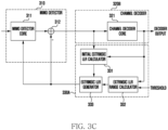
- FIG. 3C is a block diagram of an iterative detection and decoding (IDD) receiver in a wireless communication system using MIMO and channel code by connecting according to an embodiment of the disclosure.
- IDD iterative detection and decoding
- FIGS. 3B and 3C will be described in comparison.
- FIG. 3C illustrates a form implemented by the channel decoder 320B and the feedback compensator 330A.
- the channel decoder 320 may be implemented only with the channel decoder core 321 described with reference to FIGS. 3A and 3B .
- the configuration of the initial extrinsic LLR calculator 331, the extrinsic LLR range calculator 332, and the extrinsic LLR generator 333 described with reference to FIG. 3B may be in a form of configuring the feedback compensator 330A.
- FIG. 3C respective block configuration and a connection relationship between each block are the same as described in FIG. 3B .
- the examples illustrated like different configurations in FIGS. 3B and 3C may be classified according to an implementation method of a module if an actual product is implemented.
- the channel decoder 320B of FIG. 3C it may be necessary to redesign the channel decoder itself.
- the burden of design may be reduced.
- the feedback compensator 330A is added, there is an advantage that the change in the implementation of the receiver is reduced.
- the implementation method may generate the same effect as that of FIG. 3B .
- FIG. 3D is a block diagram of an iterative detection and decoding (IDD) receiver in a wireless communication system using MIMO and channel code by connecting according to an embodiment of the disclosure.
- IDD iterative detection and decoding
- FIGS. 3B , 3C , and 3D will be described in comparison.
- FIG. 3D illustrates a form implemented by the channel decoder 320 and the feedback compensator 330B. It should be noted that the channel decoder 320 has the same form as that of FIG. 3A . In the previous description of FIG. 3B , it has been described that the operation of the initial extrinsic LLR calculator 331 may be in a form of performing the same operation as that of the second adder described above. Accordingly, the channel decoder 320 may be used as it is without any other design change.
- the feedback compensator 330B may be implemented only by the extrinsic LLR range calculator 332 and the extrinsic LLR generator 333.
- their connection configuration corresponds to a case which the initial extrinsic LLR calculator 331 is replaced with the second adder 322 when compared to FIG. 3B , so the operation of other configurations may be applied in the method described in FIG. 3B above.
- FIG. 3D If implemented as shown in FIG. 3D , in contrast to FIG. 3C , there is an advantage that the existing channel decoder itself may be used as it is when implementing an actual product. Accordingly, there is an advantage that a change in the implementation of the receiver is reduced by adding only the feedback compensator 330B newly. In addition, even if the method of FIG. 3D is adopted, since the implementation method of FIG. 3D has the same configuration as that of FIG. 3B , the implementation method may generate the same effect as that of FIG. 3B .
- FIG. 4 is a statistical characteristic graph for confirming a correlation between a posteriori probability LLR value and an extrinsic LLR value in a channel detector according to an embodiment of the disclosure.
- the y-axis illustrates the EXT LLR value
- the x-axis illustrates an APP LLR value of the channel detector. It may be confirmed by the trend line of reference numeral 401 illustrated in FIG. 4 that the APP LLR value and the EXT LLR value have a proportional relationship. Therefore, in the disclosure, the extrinsic LLR may be efficiently calculated using statistical characteristic between the extrinsic LLR and the APP LLR.
- a sign indicates whether a bit indicated by the corresponding LLR is 0 or 1.
- FIG. 5 is a control flowchart for an operation of determining an output LLR value of an extrinsic LLR generator according to an embodiment of the disclosure.
- FIG. 3B Prior to description with reference to FIG. 5 , an operation of the disclosure will be described using the configuration of FIG. 3B . It should be noted that this is only using one drawing for convenience of description, and the same operation may be performed if the configuration of FIGS. 3C and/or 3D is used.
- the extrinsic LLR generator 333 may receive L EXT,init , which is an output LLR value of the initial extrinsic LLR calculator 331, and an upper threshold TH upper and/or a lower threshold TH lower received from the extrinsic LLR range calculator 332.
- the extrinsic LLR generator 333 may check (or identify) whether L EXT,init , which is an output LLR value of the initial extrinsic LLR calculator 331, is greater than the upper threshold TH upper . As a result of the check in operation 502, if L EXT,init , which is the output LLR value of the initial extrinsic LLR calculator 331, is greater than the upper threshold TH upper , the extrinsic LLR generator 333 may perform operation 504.
- the extrinsic LLR generator 333 may determine and output the EXT LLR value, which is the output of the channel decoder 320A, as the upper threshold TH upper , since the L EXT,init , which is the output LLR value of the initial extrinsic LLR calculator 331, is greater than the upper threshold TH upper .
- the extrinsic LLR generator 333 may compare L EXT,init , which is the output LLR value of the initial extrinsic LLR calculator 331, with the lower threshold TH lower , since the L EXT,init , which is the output LLR value of the initial extrinsic LLR calculator 331, is equal to the upper threshold TH upper or less than the upper threshold TH upper . That is, in operation 506, the extrinsic LLR generator 333 may examine (or identify) whether L EXT,init , which is the output LLR value of the initial extrinsic LLR calculator 331, is less than the lower threshold TH lower .
- the extrinsic LLR generator 333 may perform operation 508.
- L EXT,init which is the output LLR value of the initial extrinsic LLR calculator 331
- the extrinsic LLR generator 333 may perform operation 510.
- the extrinsic LLR generator 333 may determine and output the EXT LLR value, which is the output of the channel decoder 320A, as the lower threshold TH lower , since the L EXT,init , which is the output LLR value of the initial extrinsic LLR calculator 331, is less than the lower threshold TH lower .
- the extrinsic LLR generator 333 may determine the output value of the extrinsic LLR generator 333 as L EXT,init , which is the output LLR value of the initial extrinsic LLR calculator 331, since the L EXT,init , which is the output LLR value of the initial extrinsic LLR calculator 331, is equal to the lower threshold TH lower or greater than the lower threshold TH lower .
- L EXT,init which is the output LLR values of the initial extrinsic LLR calculator 331, exist between the lower threshold TH lower and the upper threshold TH upper .
- the condition according to the upper threshold is checked first, but a method of first checking the condition according to the lower threshold may also be understood as an embodiment of the disclosure.
- the output LLR value of the initial extrinsic LLR calculator 331 is in a form compared once with the upper threshold and the lower threshold, respectively, but a method of checking at once whether the output LLR value of the initial extrinsic LLR calculator 331 is within the range within the upper threshold and the lower threshold may be implemented.
- FIG. 6 is a comparison graph of simulations when a channel decoder is implemented with 8bits in a wireless communication system using MIMO and a channel code by connecting according to an embodiment of the disclosure.
- a priori LLR is -127 and TH is set to 31
- a simulation graph 610 according to the prior art and a simulation graph 620 according to the disclosure are illustrated.
- a priori LLR has a value of -127 due to the good receiving environment, there is a high probability that the extrinsic LLR is also calculated as -127 as shown in FIG. 6 . If the extrinsic LLR is -127, the APP LLR must be calculated as -254, but due to the fixed-point implementation, the APP LLR is saturated with -127 and calculated.
- the EXT LLR is calculated in the vicinity of the APP LLR.
- an EXT LLR that is not normal (out of the statistical range) may be generated as shown in reference numeral 610 of FIG. 6 .
- an EXT LLR such as reference numeral 610 may be made into the EXT LLR in the vicinity (so as to be within a statistical range) of the APP LLR such as reference numeral 620.
- the graph of the origin of reference numeral 610 generates an EXT LLR of about 130.
- the method proposed in the disclosure limits the size of the extrinsic LLR according to the size of the APP LLR, it may be seen that the actual extrinsic LLR value of -127 is output.
- the value in Table 2 represents a TPUT gain compared to a receiver without IDD in a given SNR. Since the LDPC coding using an 8-bit LLR is used, if TH is 127, it indicates performance according to the existing extrinsic LLR generation method. As shown in Table 2, in case that using the extrinsic LLR generation method according to the proposed method compared to the existing extrinsic LLR generation method, a performance gain of about 8% may be obtained by using an appropriate TH. Therefore, if the method and device according to the disclosure are applied, there is an advantage in that decoding performance may be improved.
Landscapes
- Engineering & Computer Science (AREA)
- Computer Networks & Wireless Communication (AREA)
- Signal Processing (AREA)
- Power Engineering (AREA)
- Mobile Radio Communication Systems (AREA)
- Radio Transmission System (AREA)
Applications Claiming Priority (3)
| Application Number | Priority Date | Filing Date | Title |
|---|---|---|---|
| KR20220028358 | 2022-03-04 | ||
| KR1020220043525A KR20230131052A (ko) | 2022-03-04 | 2022-04-07 | 무선 통신 시스템에서 복호 장치 및 방법 |
| PCT/KR2023/002361 WO2023167453A1 (ko) | 2022-03-04 | 2023-02-17 | 무선 통신 시스템에서 복호 장치 및 방법 |
Publications (2)
| Publication Number | Publication Date |
|---|---|
| EP4475469A1 true EP4475469A1 (de) | 2024-12-11 |
| EP4475469A4 EP4475469A4 (de) | 2025-06-04 |
Family
ID=87883997
Family Applications (1)
| Application Number | Title | Priority Date | Filing Date |
|---|---|---|---|
| EP23763652.7A Pending EP4475469A4 (de) | 2022-03-04 | 2023-02-17 | Dekodierungsvorrichtung und -verfahren in einem drahtlosen kommunikationssystem |
Country Status (3)
| Country | Link |
|---|---|
| US (1) | US12132533B2 (de) |
| EP (1) | EP4475469A4 (de) |
| WO (1) | WO2023167453A1 (de) |
Families Citing this family (2)
| Publication number | Priority date | Publication date | Assignee | Title |
|---|---|---|---|---|
| EP4475469A4 (de) * | 2022-03-04 | 2025-06-04 | Samsung Electronics Co., Ltd | Dekodierungsvorrichtung und -verfahren in einem drahtlosen kommunikationssystem |
| US20260088929A1 (en) * | 2024-09-25 | 2026-03-26 | Qualcomm Incorporated | Machine learning based adaptive quantization for low density parity check |
Family Cites Families (70)
| Publication number | Priority date | Publication date | Assignee | Title |
|---|---|---|---|---|
| US6885711B2 (en) * | 2001-06-27 | 2005-04-26 | Qualcomm Inc | Turbo decoder with multiple scale selections |
| US7154936B2 (en) * | 2001-12-03 | 2006-12-26 | Qualcomm, Incorporated | Iterative detection and decoding for a MIMO-OFDM system |
| US6757337B2 (en) * | 2002-09-05 | 2004-06-29 | Motorola, Inc. | Coding-assisted MIMO joint detection and decoding |
| US6819630B1 (en) * | 2002-09-20 | 2004-11-16 | The United States Of America As Represented By The Secretary Of The Navy | Iterative decision feedback adaptive equalizer |
| US7317770B2 (en) * | 2003-02-28 | 2008-01-08 | Nec Laboratories America, Inc. | Near-optimal multiple-input multiple-output (MIMO) channel detection via sequential Monte Carlo |
| US6813219B1 (en) * | 2003-09-15 | 2004-11-02 | The United States Of America As Represented By The Secretary Of The Navy | Decision feedback equalization pre-processor with turbo equalizer |
| EP1521414B1 (de) * | 2003-10-03 | 2008-10-29 | Kabushiki Kaisha Toshiba | Verfahren und Vorrichtung zur Kugeldekodierung |
| US7849377B2 (en) * | 2003-12-22 | 2010-12-07 | Koninklijke Philips Electronics N.V. | SISO decoder with sub-block processing and sub-block based stopping criterion |
| US8209579B2 (en) * | 2004-03-31 | 2012-06-26 | Intel Corporation | Generalized multi-threshold decoder for low-density parity check codes |
| US7243287B2 (en) * | 2004-05-03 | 2007-07-10 | Broadcom Corporation | Decoding LDPC (Low Density Parity Check) code and graphs using multiplication (or addition in log-domain) on both sides of bipartite graph |
| US7848440B2 (en) * | 2005-07-07 | 2010-12-07 | University Of Utah Research Foundation | Multi-channel communication method and apparatus using plural Markov Chain Monte Carlo simulations |
| US7457367B2 (en) * | 2004-07-07 | 2008-11-25 | University Of Utah Research Foundation | Detector and method for estimating data probability in a multi-channel receiver |
| DE102005010006B4 (de) * | 2005-03-04 | 2006-12-07 | Infineon Technologies Ag | Verfahren und Vorrichtung zum Terminieren einer iterativen Turbo-Dekodierung |
| US7502982B2 (en) * | 2005-05-18 | 2009-03-10 | Seagate Technology Llc | Iterative detector with ECC in channel domain |
| KR100923915B1 (ko) | 2005-12-16 | 2009-10-28 | 삼성전자주식회사 | 다중 안테나 시스템에서 반복 검출 및 복호 수신 장치 및방법 |
| US7984367B1 (en) * | 2006-07-25 | 2011-07-19 | Marvell International Ltd. | Method for iterative decoding in the presence of burst errors |
| KR100918734B1 (ko) * | 2006-07-27 | 2009-09-24 | 삼성전자주식회사 | 다중입력 다중출력 통신 시스템의 오류 정정 장치 및 방법 |
| RU2435298C2 (ru) * | 2006-11-01 | 2011-11-27 | Квэлкомм Инкорпорейтед | Турбо-перемежитель для высоких скоростей передачи данных |
| KR101244303B1 (ko) | 2006-11-09 | 2013-03-19 | 한국과학기술원 | 다중 안테나 시스템에서 수신장치 및 방법 |
| KR100949987B1 (ko) * | 2007-01-04 | 2010-03-26 | 삼성전자주식회사 | 무선통신시스템에서 수신 장치 및 방법 |
| KR100993422B1 (ko) * | 2007-12-07 | 2010-11-09 | 한국전자통신연구원 | 반복 수신 장치 및 반복 복호 장치 |
| JP2010011119A (ja) * | 2008-06-27 | 2010-01-14 | Nec Electronics Corp | 復号方法および復号装置 |
| US8238488B1 (en) * | 2008-09-02 | 2012-08-07 | Marvell International Ltd. | Multi-stream maximum-likelihood demodulation based on bitwise constellation partitioning |
| US8411806B1 (en) * | 2008-09-03 | 2013-04-02 | Marvell International Ltd. | Method and apparatus for receiving signals in a MIMO system with multiple channel encoders |
| US8321744B2 (en) * | 2008-09-16 | 2012-11-27 | Analog Devices, Inc. | Channel adaptive iterative turbo decoder system and method |
| EP2340507A4 (de) * | 2009-03-05 | 2012-05-30 | Lsi Corp | Verbesserte turboausgleichsverfahren für iterative decoder |
| US8601352B1 (en) * | 2009-07-30 | 2013-12-03 | Apple Inc. | Efficient LDPC codes |
| US8559543B1 (en) * | 2009-10-09 | 2013-10-15 | Marvell International Ltd. | Soft sphere decoder for MIMO maximum likelihood demodulation |
| US8542724B1 (en) * | 2010-09-13 | 2013-09-24 | The United States Of America As Represented By The Secretary Of The Navy | Iterative joint minimum mean square error decision feedback equalizer and turbo decoder |
| US8549387B2 (en) * | 2010-11-04 | 2013-10-01 | Himax Media Solutions, Inc. | System and method of decoding LDPC code blocks |
| JP2012178727A (ja) * | 2011-02-25 | 2012-09-13 | Sharp Corp | 受信装置、送信装置、受信方法、送信方法、プログラムおよび無線通信システム |
| US8774326B2 (en) * | 2011-04-08 | 2014-07-08 | Samsung Electronics Co., Ltd. | Receiver system and method of operation thereof |
| WO2013024838A1 (ja) * | 2011-08-15 | 2013-02-21 | シャープ株式会社 | 無線送信装置、無線受信装置、プログラム、集積回路および無線通信システム |
| JP2013115542A (ja) | 2011-11-28 | 2013-06-10 | Toshiba Corp | スケーリング決定装置及び方法 |
| US8713414B2 (en) * | 2012-01-26 | 2014-04-29 | Telefonaktiebolager L M Ericsson (Publ) | Method and apparatus for soft information transfer between constituent processor circuits in a soft-value processing apparatus |
| GB2508132A (en) * | 2012-10-03 | 2014-05-28 | Richard Beale | MIMO receiver with iterative decoding |
| US8749408B1 (en) * | 2012-12-27 | 2014-06-10 | Mediatek Singapore Pte. Ltd. | Methods for simplified MMI VQ based HARQ buffer reduction for LTE |
| US9490938B1 (en) * | 2014-01-06 | 2016-11-08 | Marvell International Ltd. | Systems and methods for performing iterative interference cancellation |
| FR3023102A1 (fr) * | 2014-06-27 | 2016-01-01 | Orange | Procede de transmission dynamique et selectif fd-dsdf d'un signal numerique pour un systeme mamrc avec plusieurs relais full-duplex, produit programme et dispositif relais correspondants |
| WO2016030758A2 (en) * | 2014-08-27 | 2016-03-03 | MagnaCom Ltd. | Multiple input multiple output communications over nonlinear channels using orthogonal frequency division multiplexing |
| KR102214101B1 (ko) * | 2014-09-05 | 2021-02-09 | 삼성전자주식회사 | 반복 검출 및 복호 수신 방법 및 장치 |
| KR101559344B1 (ko) * | 2014-12-04 | 2015-10-14 | 서울과학기술대학교 산학협력단 | 협력적 빔포밍 시스템을 위한 최적 및 준최적 로그 유사도율 산출 장치 및 방법 |
| US20160173130A1 (en) * | 2014-12-10 | 2016-06-16 | Qualcomm Incorporated | Early decode attempt of lower rate lte code blocks that are repeat combined multiple times |
| WO2016115531A1 (en) * | 2015-01-15 | 2016-07-21 | Huawei Technologies Co., Ltd. | System and method for a message passing algorithm |
| EP3048766B1 (de) | 2015-01-22 | 2019-07-24 | Vodafone GmbH | Doppeliterativer MIMO-Empfänger |
| JP6507047B2 (ja) * | 2015-02-10 | 2019-04-24 | 日本放送協会 | 送信装置、受信装置、及び半導体チップ |
| KR102240281B1 (ko) * | 2015-04-10 | 2021-04-14 | 삼성전자주식회사 | 송신 신호를 검출하기 위한 장치 및 방법 |
| MX2021004799A (es) * | 2015-07-23 | 2022-12-07 | Samsung Electronics Co Ltd | Aparato de transmision, aparato de recepcion, y metodos de control de los mismos. |
| US9660845B2 (en) * | 2015-10-06 | 2017-05-23 | Huawei Technologies Co., Ltd. | System and method for state reduction in trellis equalizers using bounded state enumeration |
| US9998949B2 (en) * | 2015-12-31 | 2018-06-12 | Facebook, Inc. | Switched diversity in data link layers of directional networks |
| US10182439B2 (en) * | 2016-02-16 | 2019-01-15 | Samsung Electronics Co., Ltd | Method and apparatus for data-aided iterative channel estimation |
| US9917723B2 (en) * | 2016-03-09 | 2018-03-13 | Futurewei Technologies, Inc. | Efficient methods and recursive/scalable circuit architectures for QAM symbol mean and variance estimations |
| KR102568716B1 (ko) * | 2016-08-02 | 2023-08-21 | 삼성전자주식회사 | Ldpc 코드의 디코딩을 위한 장치 및 방법 |
| US20180123615A1 (en) * | 2016-11-02 | 2018-05-03 | Qualcomm Incorporated | Non-linear log-likelihood ratio quantization techniques for ldpc decoder architecture |
| US10270625B2 (en) * | 2016-12-19 | 2019-04-23 | Futurewei Technologies, Inc. | Hardware virtualization for mean and variance estimations of QAM symbols |
| KR101832901B1 (ko) | 2017-01-11 | 2018-02-27 | 서울과학기술대학교 산학협력단 | 반복적인 타부 서치를 이용한 다중 안테나 통신시스템의 연판정 디코딩 장치 및 방법 |
| CN110741553B (zh) * | 2017-06-22 | 2023-11-03 | 瑞典爱立信有限公司 | 用于前向纠错解码的神经网络 |
| US10103843B1 (en) * | 2017-12-08 | 2018-10-16 | Qualcomm Incorporated | On the fly interleaving/rate matching and deinterleaving/de-rate matching for 5G NR |
| KR102470863B1 (ko) * | 2018-03-09 | 2022-11-28 | 삼성전자주식회사 | 간섭량 측정 방법 및 장치 |
| US10615912B2 (en) * | 2018-08-22 | 2020-04-07 | Samsung Electronics Co., Ltd. | Apparatuses, computer-readable media, and methods for single dimension maximal likelihood symbol detection |
| US11108410B1 (en) * | 2018-08-24 | 2021-08-31 | Xilinx, Inc. | User-programmable LDPC decoder |
| US10819468B2 (en) * | 2018-12-05 | 2020-10-27 | Black Lattice Technologies, Inc. | Stochastic linear detection |
| KR102400999B1 (ko) * | 2018-12-27 | 2022-05-23 | 삼성전자주식회사 | 복수의 무선 신호들을 결합하는 방법 및 장치 |
| US11558147B2 (en) * | 2020-02-11 | 2023-01-17 | Marvell Asia Pte, LTD | Methods and apparatus for decoding received uplink transmissions using log-likelihood ratio (LLR) optimization |
| GB202010773D0 (en) * | 2020-07-13 | 2020-08-26 | Accelercomm Ltd | Correlator distribution investigation and conversion to symbol LLRs |
| KR20230107872A (ko) * | 2020-10-15 | 2023-07-18 | 삼성전자주식회사 | 통신 또는 방송 시스템에서 데이터 복호화 방법 및 장치 |
| US11223447B1 (en) * | 2021-03-31 | 2022-01-11 | Seagate Technology Llc | Multiple detector data channel and data detection utilizing different cost functions |
| EP4475469A4 (de) * | 2022-03-04 | 2025-06-04 | Samsung Electronics Co., Ltd | Dekodierungsvorrichtung und -verfahren in einem drahtlosen kommunikationssystem |
| US12068811B2 (en) * | 2022-08-12 | 2024-08-20 | Qualcomm Incorporated | LDPC base graph selection systems and methods |
| US11799700B1 (en) * | 2022-08-31 | 2023-10-24 | Qualcomm Incorporated | Decoding multi-level coded (MLC) systems |
-
2023
- 2023-02-17 EP EP23763652.7A patent/EP4475469A4/de active Pending
- 2023-02-17 WO PCT/KR2023/002361 patent/WO2023167453A1/ko not_active Ceased
- 2023-02-23 US US18/173,379 patent/US12132533B2/en active Active
Also Published As
| Publication number | Publication date |
|---|---|
| US12132533B2 (en) | 2024-10-29 |
| WO2023167453A1 (ko) | 2023-09-07 |
| EP4475469A4 (de) | 2025-06-04 |
| US20230318665A1 (en) | 2023-10-05 |
Similar Documents
| Publication | Publication Date | Title |
|---|---|---|
| EP4475469A1 (de) | Dekodierungsvorrichtung und -verfahren in einem drahtlosen kommunikationssystem | |
| US11290127B2 (en) | Apparatus and method for offset optimization for low-density parity-check (LDPC) code | |
| KR102844973B1 (ko) | 안테나를 포함하는 전자 장치 및 상기 전자 장치의 전력 백 오프 제어 방법 | |
| US12250074B2 (en) | Autoencoders with list decoding for reliable data transmission over noisy channels and methods thereof | |
| CN112583421B (zh) | 用于识别和解码极化码中的里德穆勒码的系统和方法 | |
| KR102820305B1 (ko) | 폴라 코드에서 리드 뮬러 코드를 식별 및 디코딩하는 시스템 및 방법 | |
| KR102880895B1 (ko) | 신경망 자기 정정 최소합 복호기 및 이를 포함하는 전자 장치 | |
| EP4568121A1 (de) | Elektronische vorrichtung mit mehreren antennen | |
| KR20230131052A (ko) | 무선 통신 시스템에서 복호 장치 및 방법 | |
| US12547253B2 (en) | Keyboard device and electronic device connected with keyboard device | |
| US20220385305A1 (en) | Neural self-corrected min-sum decoder and an electronic device comprising the decoder | |
| KR20260030532A (ko) | 무선 이동통신 시스템에서 노이지 임베딩을 이용한 복호화 방법 및 장치 | |
| KR102844789B1 (ko) | 무선 통신을 수행하는 전자 장치 및 그 방법 | |
| KR20250176902A (ko) | 카메라 구동에 따른 통신의 최대 송신 전력 제어 방법 및 그 전자 장치 | |
| US12185253B2 (en) | Electronic device and method for adjusting output power of radio frequency signal to be output to antenna | |
| US20240137150A1 (en) | Methods and systems for early termination of iterative detection and decoding | |
| EP4236114B1 (de) | Elektronische vorrichtung und betriebsverfahren dafür | |
| KR20250156573A (ko) | 안테나 스위칭을 제어하는 전자 장치 및 그 동작 방법 | |
| EP4284136A1 (de) | Leiterplattenanordnung | |
| KR20250075402A (ko) | 키보드 장치 및 키보드 장치와 연결되는 전자 장치 | |
| EP4279952A1 (de) | Elektronische vorrichtung zur bestimmung der position einer externen elektronischen vorrichtung und betriebsverfahren einer elektronischen vorrichtung | |
| KR20260035432A (ko) | 무선 통신 시스템에서 신경망 복호기 학습을 위한 방법 및 장치 | |
| KR20250032725A (ko) | 하향 링크 채널을 예측하는 시스템 및 방법 | |
| KR20240175273A (ko) | 송신 안테나를 변경하는 전자 장치 및 그 동작 방법 | |
| KR20260013860A (ko) | 반사 계수에 기반하여 안테나 상태를 확인하는 전자 장치, 방법, 및 비 일시적 컴퓨터 판독가능 저장 매체 |
Legal Events
| Date | Code | Title | Description |
|---|---|---|---|
| STAA | Information on the status of an ep patent application or granted ep patent |
Free format text: STATUS: THE INTERNATIONAL PUBLICATION HAS BEEN MADE |
|
| PUAI | Public reference made under article 153(3) epc to a published international application that has entered the european phase |
Free format text: ORIGINAL CODE: 0009012 |
|
| STAA | Information on the status of an ep patent application or granted ep patent |
Free format text: STATUS: REQUEST FOR EXAMINATION WAS MADE |
|
| 17P | Request for examination filed |
Effective date: 20240904 |
|
| AK | Designated contracting states |
Kind code of ref document: A1 Designated state(s): AL AT BE BG CH CY CZ DE DK EE ES FI FR GB GR HR HU IE IS IT LI LT LU LV MC ME MK MT NL NO PL PT RO RS SE SI SK SM TR |
|
| A4 | Supplementary search report drawn up and despatched |
Effective date: 20250508 |
|
| RIC1 | Information provided on ipc code assigned before grant |
Ipc: H04B 7/08 20060101ALI20250501BHEP Ipc: H04L 1/06 20060101ALI20250501BHEP Ipc: H04B 1/7107 20110101ALI20250501BHEP Ipc: H04L 25/03 20060101ALI20250501BHEP Ipc: H04B 7/0413 20170101ALI20250501BHEP Ipc: H04L 1/00 20060101AFI20250501BHEP |
|
| DAV | Request for validation of the european patent (deleted) | ||
| DAX | Request for extension of the european patent (deleted) |