EP4236114B1 - Elektronische vorrichtung und betriebsverfahren dafür - Google Patents
Elektronische vorrichtung und betriebsverfahren dafür Download PDFInfo
- Publication number
- EP4236114B1 EP4236114B1 EP22739583.7A EP22739583A EP4236114B1 EP 4236114 B1 EP4236114 B1 EP 4236114B1 EP 22739583 A EP22739583 A EP 22739583A EP 4236114 B1 EP4236114 B1 EP 4236114B1
- Authority
- EP
- European Patent Office
- Prior art keywords
- frequency
- spread spectrum
- spread
- spectrum method
- electronic device
- Prior art date
- Legal status (The legal status is an assumption and is not a legal conclusion. Google has not performed a legal analysis and makes no representation as to the accuracy of the status listed.)
- Active
Links
Images


Classifications
-
- H—ELECTRICITY
- H04—ELECTRIC COMMUNICATION TECHNIQUE
- H04B—TRANSMISSION
- H04B15/00—Suppression or limitation of noise or interference
- H04B15/02—Reducing interference from electric apparatus by means located at or near the interfering apparatus
-
- H—ELECTRICITY
- H04—ELECTRIC COMMUNICATION TECHNIQUE
- H04L—TRANSMISSION OF DIGITAL INFORMATION, e.g. TELEGRAPHIC COMMUNICATION
- H04L27/00—Modulated-carrier systems
- H04L27/0014—Carrier regulation
-
- H—ELECTRICITY
- H04—ELECTRIC COMMUNICATION TECHNIQUE
- H04B—TRANSMISSION
- H04B1/00—Details of transmission systems, not covered by a single one of groups H04B3/00 - H04B13/00; Details of transmission systems not characterised by the medium used for transmission
- H04B1/69—Spread spectrum techniques
- H04B1/707—Spread spectrum techniques using direct sequence modulation
-
- H—ELECTRICITY
- H04—ELECTRIC COMMUNICATION TECHNIQUE
- H04L—TRANSMISSION OF DIGITAL INFORMATION, e.g. TELEGRAPHIC COMMUNICATION
- H04L5/00—Arrangements affording multiple use of the transmission path
- H04L5/003—Arrangements for allocating sub-channels of the transmission path
- H04L5/0053—Allocation of signalling, i.e. of overhead other than pilot signals
-
- H—ELECTRICITY
- H04—ELECTRIC COMMUNICATION TECHNIQUE
- H04W—WIRELESS COMMUNICATION NETWORKS
- H04W72/00—Local resource management
- H04W72/04—Wireless resource allocation
- H04W72/044—Wireless resource allocation based on the type of the allocated resource
- H04W72/0453—Resources in frequency domain, e.g. a carrier in FDMA
-
- H—ELECTRICITY
- H04—ELECTRIC COMMUNICATION TECHNIQUE
- H04B—TRANSMISSION
- H04B2215/00—Reducing interference at the transmission system level
- H04B2215/064—Reduction of clock or synthesizer reference frequency harmonics
-
- H—ELECTRICITY
- H04—ELECTRIC COMMUNICATION TECHNIQUE
- H04L—TRANSMISSION OF DIGITAL INFORMATION, e.g. TELEGRAPHIC COMMUNICATION
- H04L27/00—Modulated-carrier systems
- H04L27/0014—Carrier regulation
- H04L2027/0044—Control loops for carrier regulation
- H04L2027/0046—Open loops
- H04L2027/0048—Frequency multiplication
Definitions
- the following description relates to an electronic device and an operation method thereof.
- EMI electromagnetic interference
- SSCG spread spectrum clock generation
- JP 2008 301482 A discloses an electronic apparatus with a wireless unit includes a multiplier to receive a clock signal at a predetermined frequency.
- the electronic apparatus further includes a modulator configured to modulate the frequency of the clock signal generated by the multiplier, and a controller configured to change the frequency of the clock signal generated by the multiplier and a modulation rate of the modulation performed by the modulator according to a state of the electronic apparatus.
- US 2012/218017 Al discloses a method for adjusting the frequency of one or more clock signals used by a device.
- the one or more clock signals are adjusted by a determined amount when a channel quality metric of an RF channel in use by the device indicates a degradation in the reception quality.
- an electronic device that controls a spread spectrum clock generator to output a clock signal that reduces EMI without deteriorating connected communication performance by changing a spread spectrum setting may be provided.
- degradation of connected communication performance may be prevented by controlling a spread spectrum clock generator (SSCG).
- SSCG spread spectrum clock generator
- electromagnetic interference may be reduced by controlling an SSCG.
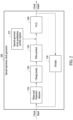
- FIG. 1 is a block diagram illustrating an electronic device in a network environment according to various embodiments.
- FIG. 1 is a block diagram illustrating an electronic device 101 in a network environment 100 according to various embodiments.
- the electronic device 101 in the network environment 100 may communicate with an electronic device 102 via a first network 198 (e.g., a short-range wireless communication network), or communicate with at least one of an electronic device 104 or a server 108 via a second network 199 (e.g., a long-range wireless communication network).
- the electronic device 101 may communicate with the electronic device 104 via the server 108.
- the electronic device 101 may include a processor 120, a memory 130, an input module 150, a sound output module 155, a display module 160, an audio module 170, a sensor module 176, an interface 177, a connecting terminal 178, a haptic module 179, a camera module 180, a power management module 188, a battery 189, a communication module 190, a subscriber identification module (SIM) 196, or an antenna module 197.
- at least one (e.g., the connecting terminal 178) of the above components may be omitted from the electronic device 101, or one or more other components may be added in the electronic device 101.
- some (e.g., the sensor module 176, the camera module 180, or the antenna module 197) of the components may be integrated as a single component (e.g., the display module 160).
- the processor 120 may execute, for example, software (e.g., a program 140) to control at least one other component (e.g., a hardware or software component) of the electronic device 101 connected to the processor 120, and may perform various data processing or computation.
- the processor 120 may store a command or data received from another component (e.g., the sensor module 176 or the communication module 190) in a volatile memory 132, process the command or the data stored in the volatile memory 132, and store resulting data in a non-volatile memory 134.
- the processor 120 may include a main processor 121 (e.g., a central processing unit (CPU) or an application processor (AP)) or an auxiliary processor 123 (e.g., a graphics processing unit (GPU), a neural processing unit (NPU), an image signal processor (ISP), a sensor hub processor, or a communication processor (CP)) that is operable independently from, or in conjunction with the main processor 121.
- a main processor 121 e.g., a central processing unit (CPU) or an application processor (AP)
- auxiliary processor 123 e.g., a graphics processing unit (GPU), a neural processing unit (NPU), an image signal processor (ISP), a sensor hub processor, or a communication processor (CP)
- the auxiliary processor 123 may be adapted to consume less power than the main processor 121 or to be specific to a specified function.
- the auxiliary processor 123 may be implemented as separate from, or as part of the main processor 121.
- the auxiliary processor 123 may control at least some of functions or states related to at least one (e.g., the display module 160, the sensor module 176, or the communication module 190) of the components of the electronic device 101, instead of the main processor 121 while the main processor 121 is in an inactive (e.g., sleep) state, or together with the main processor 121 while the main processor 121 is in an active state (e.g., executing an application).
- the auxiliary processor 123 e.g., an ISP or a CP
- the auxiliary processor 123 may include a hardware structure specified for artificial intelligence model processing.
- An artificial intelligence model may be generated through machine learning. Such learning may be performed, for example, by the electronic device 101 in which an artificial intelligence model is executed, or via a separate server (e.g., the server 108). Learning algorithms may include, but are not limited to, for example, supervised learning, unsupervised learning, semi-supervised learning, or reinforcement learning.
- the artificial intelligence model may include a plurality of artificial neural network layers.
- An artificial neural network may include, for example, a deep neural network (DNN), a convolutional neural network (CNN), a recurrent neural network (RNN), a restricted Boltzmann machine (RBM), a deep belief network (DBN), a bidirectional recurrent deep neural network (BRDNN), a deep Q-network, or a combination of two or more thereof, but is not limited thereto.
- the artificial intelligence model may additionally or alternatively include a software structure other than the hardware structure.
- the memory 130 may store various pieces of data used by at least one component (e.g., the processor 120 or the sensor module 176) of the electronic device 101.
- the various pieces of data may include, for example, software (e.g., the program 140) and input data or output data for a command related thereto.
- the memory 130 may include the volatile memory 132 or the non-volatile memory 134.
- the program 140 may be stored as software in the memory 130 and may include, for example, an operating system (OS) 142, middleware 144, or an application 146.
- OS operating system
- middleware middleware
- application application
- the input module 150 may receive a command or data to be used by another component (e.g., the processor 120) of the electronic device 101, from the outside (e.g., a user) of the electronic device 101.
- the input module 150 may include, for example, a microphone, a mouse, a keyboard, a key (e.g., a button), or a digital pen (e.g., a stylus pen).
- the sound output module 155 may output a sound signal to the outside of the electronic device 101.
- the sound output module 155 may include, for example, a speaker or a receiver.
- the speaker may be used for general purposes, such as playing multimedia or playing record.
- the receiver may be used to receive an incoming call. According to an embodiment, the receiver may be implemented as separate from, or as part of the speaker.
- the display module 160 may visually provide information to the outside (e.g., a user) of the electronic device 101.
- the display module 160 may include, for example, a display, a hologram device, or a projector and control circuitry to control a corresponding one of the display, hologram device, and projector.
- the display module 160 may include a touch sensor adapted to sense a touch, or a pressure sensor adapted to measure the intensity of force incurred by the touch.
- the audio module 170 may convert a sound into an electrical signal and vice versa. According to an embodiment, the audio module 170 may obtain the sound via the input module 150 or output the sound via the sound output module 155 or an external electronic device (e.g., the electronic device 102 such as a speaker or headphones) directly or wirelessly connected to the electronic device 101.
- an external electronic device e.g., the electronic device 102 such as a speaker or headphones
- the sensor module 176 may detect an operational state (e.g., power or temperature) of the electronic device 101 or an environmental state (e.g., a state of a user) external to the electronic device 101, and generate an electrical signal or data value corresponding to the detected state.
- the sensor module 176 may include, for example, a gesture sensor, a gyro sensor, an atmospheric pressure sensor, a magnetic sensor, an acceleration sensor, a grip sensor, a proximity sensor, a color sensor, an infrared (IR) sensor, a biometric sensor, a temperature sensor, a humidity sensor, or an illuminance sensor.
- the interface 177 may support one or more specified protocols to be used for the electronic device 101 to be coupled with the external electronic device (e.g., the electronic device 102) directly (e.g., by wire) or wirelessly.
- the interface 177 may include, for example, a high-definition multimedia interface (HDMI), a universal serial bus (USB) interface, a secure digital (SD) card interface, or an audio interface.
- HDMI high-definition multimedia interface
- USB universal serial bus
- SD secure digital
- the connecting terminal 178 may include a connector via which the electronic device 101 may be physically connected to the external electronic device (e.g., the electronic device 102).
- the connecting terminal 178 may include, for example, an HDMI connector, a USB connector, an SD card connector, or an audio connector (e.g., a headphone connector).
- the haptic module 179 may convert an electrical signal into a mechanical stimulus (e.g., a vibration or a movement) or an electrical stimulus which may be recognized by a user via his or her tactile sensation or kinesthetic sensation.
- the haptic module 179 may include, for example, a motor, a piezoelectric element, or an electric stimulator.
- the camera module 180 may capture a still image and moving images. According to an embodiment, the camera module 180 may include one or more lenses, image sensors, ISPs, or flashes.
- the power management module 188 may manage power supplied to the electronic device 101.
- the power management module 188 may be implemented as at least part of, for example, a power management integrated circuit (PMIC).
- PMIC power management integrated circuit
- the battery 189 may supply power to at least one component of the electronic device 101.
- the battery 189 may include, for example, a primary cell which is not rechargeable, a secondary cell which is rechargeable, or a fuel cell.
- the communication module 190 may support establishing a direct (e.g., wired) communication channel or a wireless communication channel between the electronic device 101 and the external electronic device (e.g., the electronic device 102, the electronic device 104, or the server 108) and performing communication via the established communication channel.
- the communication module 190 may include one or more CPs that are operable independently of the processor 120 (e.g., an AP) and that support a direct (e.g., wired) communication or a wireless communication.
- the communication module 190 may include a wireless communication module 192 (e.g., a cellular communication module, a short-range wireless communication module, or a global navigation satellite system (GNSS) communication module) or a wired communication module 194 (e.g., a local area network (LAN) communication module, or a power line communication (PLC) module).
- a wireless communication module 192 e.g., a cellular communication module, a short-range wireless communication module, or a global navigation satellite system (GNSS) communication module
- GNSS global navigation satellite system
- wired communication module 194 e.g., a local area network (LAN) communication module, or a power line communication (PLC) module.
- LAN local area network
- PLC power line communication
- a corresponding one of these communication modules may communicate with the external electronic device 104 via the first network 198 (e.g., a short-range communication network, such as BluetoothTM, wireless-fidelity (Wi-Fi) direct, or infrared data association (IrDA)) or the second network 199 (e.g., a long-range communication network, such as a legacy cellular network, a 5G network, a next-generation communication network, the Internet, or a computer network (e.g., a LAN or a wide area network (WAN)).
- the wireless communication module 192 may identify and authenticate the electronic device 101 in a communication network, such as the first network 198 or the second network 199, using subscriber information (e.g., international mobile subscriber identity (IMSI)) stored in the SIM 196.
- subscriber information e.g., international mobile subscriber identity (IMSI)
- the wireless communication module 192 may support a 5G network after a 4G network, and next-generation communication technology, e.g., new radio (NR) access technology.
- the NR access technology may support enhanced mobile broadband (eMBB), massive machine type communications (mMTC), or ultra-reliable and low-latency communications (URLLC).
- eMBB enhanced mobile broadband
- mMTC massive machine type communications
- URLLC ultra-reliable and low-latency communications
- the wireless communication module 192 may support a high-frequency band (e.g., a mmWave band) to achieve, e.g., a high data transmission rate.
- a high-frequency band e.g., a mmWave band
- the wireless communication module 192 may support various technologies for securing performance on a high-frequency band, such as, e.g., beamforming, massive multiple-input and multiple-output (massive MIMO), full dimensional MIMO (FD-MIMO), an array antenna, analog beamforming, or a large scale antenna.
- the wireless communication module 192 may support various requirements specified in the electronic device 101, an external electronic device (e.g., the electronic device 104), or a network system (e.g., the second network 199).
- the wireless communication module 192 may support a peak data rate (e.g., 20 Gbps or more) for implementing eMBB, loss coverage (e.g., 164 dB or less) for implementing mMTC, or U-plane latency (e.g., 0.5 ms or less for each of downlink (DL) and uplink (UL), or a round trip of 1 ms or less) for implementing URLLC.
- a peak data rate e.g., 20 Gbps or more
- loss coverage e.g., 164 dB or less
- U-plane latency e.g., 0.5 ms or less for each of downlink (DL) and uplink (UL), or a round trip of 1 ms or less
- the antenna module 197 may transmit or receive a signal or power to or from the outside (e.g., an external electronic device) of the electronic device 101.
- the antenna module 197 may include an antenna including a radiating element including a conductive material or a conductive pattern formed in or on a substrate (e.g., a printed circuit board (PCB)).
- the antenna module 197 may include a plurality of antennas (e.g., array antennas). In such a case, at least one antenna appropriate for a communication scheme used in a communication network, such as the first network 198 or the second network 199, may be selected by, for example, the communication module 190 from the plurality of antennas.
- the signal or power may be transmitted or received between the communication module 190 and the external electronic device via the at least one selected antenna.
- another component e.g., a radio frequency integrated circuit (RFIC)
- RFIC radio frequency integrated circuit
- the antenna module 197 may form a mm Wave antenna module.
- the mmWave antenna module may include a PCB, an RFIC disposed on a first surface (e.g., the bottom surface) of the PCB or adjacent to the first surface and capable of supporting a designated high-frequency band (e.g., the mmWave band), and a plurality of antennas (e.g., array antennas) disposed on a second surface (e.g., the top or a side surface) of the PCB, or adjacent to the second surface and capable of transmitting or receiving signals in the designated high-frequency band.
- At least some of the above-described components may be coupled mutually and communicate signals (e.g., commands or data) therebetween via an inter-peripheral communication scheme (e.g., a bus, general purpose input and output (GPIO), serial peripheral interface (SPI), or mobile industry processor interface (MIPI)).
- an inter-peripheral communication scheme e.g., a bus, general purpose input and output (GPIO), serial peripheral interface (SPI), or mobile industry processor interface (MIPI)
- commands or data may be transmitted or received between the electronic device 101 and the external electronic device 104 via the server 108 coupled with the second network 199.
- Each of the external electronic devices 102 and 104 may be a device of the same type as or a different type from the electronic device 101.
- all or some of operations to be executed at the electronic device 101 may be executed at one or more of external electronic devices (e.g., the external electronic devices 102 and 104, or the server 108).
- the electronic device 101 may request the one or more external electronic devices to perform at least part of the function or the service.
- the one or more external electronic devices receiving the request may perform the at least part of the function or the service requested, or an additional function or an additional service related to the request, and transfer an outcome of the performing to the electronic device 101.
- the electronic device 101 may provide the outcome, with or without further processing of the outcome, as at least part of a reply to the request.
- a cloud computing, distributed computing, mobile edge computing (MEC), or client-server computing technology may be used, for example.
- the electronic device 101 may provide ultra low-latency services using, e.g., distributed computing or MEC.
- the external electronic device 104 may include an Internet-of-things (IoT) device.
- the server 108 may be an intelligent server using machine learning and/or a neural network.
- the external electronic device 104 or the server 108 may be included in the second network 199.
- the electronic device 101 may be applied to intelligent services (e.g., a smart home, a smart city, a smart car, or healthcare) based on 5G communication technology or IoT-related technology.
- the electronic device may be one of various types of electronic devices.
- the electronic devices may include, for example, a portable communication device (e.g., a smartphone), a computer device, a portable multimedia device, a portable medical device, a camera, a wearable device, or a home appliance.
- the electronic device is not limited to those described above.
- similar reference numerals may be used to refer to similar or related elements. It is to be understood that a singular form of a noun corresponding to an item may include one or more of the things, unless the relevant context clearly indicates otherwise.
- each of such phrases as “A or B”, “at least one of A and B”, “at least one of A or B”, “A, B or C”, “at least one of A, B and C”, and “at least one of A, B, or C”, may include any one of, or all possible combinations of the items enumerated together in a corresponding one of the phrases.
- such terms as “1 st “ and “2 nd ,” or “first” and “second” may be used to simply distinguish a corresponding component from another, and does not limit the components in other aspect (e.g., importance or order).
- a component e.g., a first component
- operatively or “communicatively”, as “coupled with”, “coupled to”, “connected with”, or “connected to” another component
- the component may be coupled with the other component directly (e.g., by wire), wirelessly, or via a third component.
- module may include a unit implemented in hardware, software, or firmware, and may interchangeably be used with other terms, for example, “logic”, “logic block”, “part”, or “circuitry”.
- a module may be a single integral component, or a minimum unit or part thereof, adapted to perform one or more functions.
- the module may be implemented in a form of an application-specific integrated circuit (ASIC).
- ASIC application-specific integrated circuit
- Embodiments as set forth herein may be implemented as software (e.g., the program 140) including one or more instructions that are stored in a storage medium (e.g., an internal memory 136 or an external memory 138) that is readable by a machine (e.g., the electronic device 101).
- a processor e.g., the processor 120
- the one or more instructions may include code generated by a compiler or code executable by an interpreter.
- the machine-readable storage medium may be provided in the form of a non-transitory storage medium.
- non-transitory simply means that the storage medium is a tangible device, and does not include a signal (e.g., an electromagnetic wave), but this term does not differentiate between where data is semi-permanently stored in the storage medium and where the data is temporarily stored in the storage medium.
- a method according to embodiments of the disclosure may be included and provided in a computer program product.
- the computer program product may be traded as a product between a seller and a buyer.
- the computer program product may be distributed in the form of a machine-readable storage medium (e.g., compact disc read-only memory (CD-ROM)), or be distributed (e.g., downloaded or uploaded) online via an application store (e.g., PlayStore TM ), or between two user devices (e.g., smartphones) directly. If distributed online, at least part of the computer program product may be temporarily generated or at least temporarily stored in the machine-readable storage medium, such as a memory of the manufacturer's server, a server of the application store, or a relay server.
- CD-ROM compact disc read-only memory
- an application store e.g., PlayStore TM
- two user devices e.g., smartphones
- each component e.g., a module or a program of the above-described components may include a single entity or multiple entities, and some of the multiple entities may be separately disposed in different components. According to embodiments, one or more of the above-described components or operations may be omitted, or one or more other components or operations may be added. Alternatively or additionally, a plurality of components (e.g., modules or programs) may be integrated into a single component. In such a case, according to embodiments, the integrated component may still perform one or more functions of each of the plurality of components in the same or similar manner as they are performed by a corresponding one of the plurality of components before the integration.
- operations performed by the module, the program, or another component may be carried out sequentially, in parallel, repeatedly, or heuristically, or one or more of the operations may be executed in a different order or omitted, or one or more other operations may be added.
- FIG. 2 is a block diagram illustrating a spread spectrum clock generator (SSCG) according to various embodiments.
- SSCG spread spectrum clock generator
- an SSCG 200 may include a phase and frequency detector 210, a charge pump 220, a filter portion 230, a spread spectrum clock generation modulation profile register 235, a voltage-controlled oscillator (VCO) 240, and a divider 250.
- VCO voltage-controlled oscillator
- the SSCG 200 may be included in the electronic device 101 of FIG. 1 .
- the SSCG 200 may generate a spread spectrum clock signal for data communication of the electronic device 101 of FIG. 1 .
- a communication interface for data communication of the electronic device 101 may include, for example, universal serial bus (USB), peripheral component interconnect express (PCIe), secure digital input/output (SDIO), secure digital card (SDC), and a mobile industry processor interface (MIPI) but is not limited thereto.
- the communication interface for data communication of the electronic device 101 may include the interface 177 of FIG. 1 .
- the phase and frequency detector 210 may receive an input clock signal and a feedback signal output from the divider 250.
- the phase and frequency detector 210 may detect the phase difference and the frequency difference between the input clock signal and the feedback signal, respectively.
- the phase and frequency detector 210 may transmit the detected phase difference and the detected frequency difference to the charge pump 220.
- the charge pump 220 may provide a voltage on the detected phase difference and the detected frequency difference to the filter portion 230.
- the filter portion 230 may filter the provided voltage and filtering (e.g., low-pass filtering).
- the spread spectrum clock generation modulation profile register 235 may store a bit value for a spread spectrum method and a bit value for a spread ratio.
- the spread ratio may be a factor determining a spread bandwidth of a spread spectrum clock signal to be output from the VCO 240.
- the bit value for the spread spectrum method of the spread spectrum clock generation modulation profile register 235 may be, for example, "1".
- the bit value for the spread spectrum method of the spread spectrum clock generation modulation profile register 235 may be, for example, "0".
- the bit value for the spread ratio of the spread spectrum clock generation modulation profile register 235 may be, for example, "11"
- the bit value for the spread ratio of the spread spectrum clock generation modulation profile register 235 may be, for example, "10".
- the bit value for the spread ratio of the spread spectrum clock generation modulation profile register 235 may be, for example, "01", and when a spread ratio is, for example, 0.5%, the bit value for the spread ratio of the spread spectrum clock generation modulation profile register 235 may be, for example, "00".
- a modulator may identify a spread spectrum method to be applied through the bit value for the spread spectrum method.
- the modulator may identify a spread ratio to be applied through the bit value for the spread ratio.
- the modulator may modulate a voltage received from the filter portion 230 based on the determined spread spectrum method and the determined spread ratio and may provide the modulated voltage to the VCO 240.
- the VCO 240 may output the spread spectrum clock signal by performing oscillation according to the modulated voltage.
- the divider 250 may divide the spread spectrum clock signal output from the VCO 240, generate a feedback signal divided by a predetermined value, and provide the generated feedback signal to the phase and frequency detector 210.
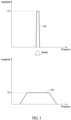
- FIG. 3 is a graph illustrating frequency band distributions when a spread spectrum is not used and when a spread spectrum is used according to various embodiments.
- FIG. 3 illustrates an example of a frequency domain signal 310 of a clock signal to which a spread spectrum is not applied and a frequency domain signal 370 of a spread spectrum clock signal.
- an area of the frequency domain signal 370 of the spread spectrum clock signal may be the same as an area of the frequency domain signal 310 of the clock signal to which the spread spectrum is not applied and accordingly, the energy of the frequency domain signal 370 is the same as that of the frequency domain signal 310.
- the frequency bandwidth of the frequency domain signal 370 of the spread spectrum clock signal may be greater than the frequency bandwidth of the frequency domain signal 310 of the clock signal to which the spread spectrum is not applied.
- a noise peak value 375 of the frequency domain signal 370 may be less than a noise peak value 315 of the frequency domain signal 310.
- electromagnetic interference (EMI) emitted from an electronic device e.g., the electronic device 101
- FIGS. 4A and 4B are graphs illustrating frequency band distributions according to a spread spectrum method of a spread spectrum clock signal according to an embodiment.
- FIG. 4A illustrates a frequency domain signal 420 of a clock signal to which a spread spectrum method is not applied and a frequency domain signal 430 of a spread spectrum clock signal generated by applying the down-spread spectrum method and a spread ratio of 1%.
- the frequency domain signal 430 may have a frequency band of f 0 - (f 0 ⁇ 1%) to f 0 .
- FIG. 4B illustrates a frequency domain signal 480 of a clock signal to which the spread spectrum method is not applied and a frequency domain signal 490 of a spread spectrum clock signal generated by applying the center-spread spectrum method and a spread ratio of 1%.
- the frequency domain signal 490 may have a frequency band of f 0 - (f 0 ⁇ 0.5%) to f 0 + (f 0 ⁇ 0.5%).
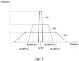
- FIG. 5 is a graph illustrating frequency band distributions according to a spread ratio of a center-spread spectrum clock signal according to an embodiment.
- a signal 540 to which a spread ratio of 1% is applied may be spread to have a frequency band expanded by 0.5% of the center frequency on both sides based on the center frequency of a signal 510 to which a spread spectrum is not applied.
- a center frequency f c of the signal 510 to which the spread spectrum is not applied is f 0
- the signal 540 to which the spread ratio of 1% is applied may have a frequency band of f 0 - (f 0 ⁇ 0.5%) to f 0 + (f 0 ⁇ 0.5%).
- a signal 570 to which a spread ratio of 2% is applied may spread a signal to have a frequency band expanded by 1% of the center frequency on both sides based on the center frequency of the signal 510 to which the spread spectrum is not applied. For example, when the center frequency f c of the signal 510 to which the spread spectrum is not applied is f 0 , the signal 570 to which the spread ratio of 2% is applied may have a frequency band of f 0 - (f 0 ⁇ 1%) to f 0 + (f 0 ⁇ 1%).
- setting a spread ratio against an operating frequency to a maximum value supported by a communication interface in a range of securing the stability of an electronic device (600 of FIG. 6 ) (e.g., the electronic device 101 of FIG. 1 ) may minimize the EMI phenomenon.
- a frequency in a range of the operating frequency and a multiplication frequency of the communication interface e.g., the interface 177 of FIG. 1
- the communication performance may be degraded when the frequency in the range of the operating frequency and the multiplication frequency overlap with the communication channel frequency.
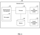
- FIGS. 6 to 11 are diagrams illustrating an operation of an electronic device according to various embodiments.
- an electronic device 600 may include a first communication module 610, a second communication module 620, an SSCG 630 (e.g., the SSCG 200 of FIG. 2 ) including a first register 635 (e.g., the spread spectrum clock modulation profile register 235), a memory 640 (e.g., the memory 130), and a processor 650 (e.g., the processor 120 of FIG. 1 ).
- a first communication module 610 e.g., the electronic device 101 of FIG. 1
- an SSCG 630 e.g., the SSCG 200 of FIG. 2
- a first register 635 e.g., the spread spectrum clock modulation profile register 235
- a memory 640 e.g., the memory 130
- a processor 650 e.g., the processor 120 of FIG. 1
- the first communication module 610 and the second communication module 620 may be included in the communication module 190 of FIG. 1 .
- the first communication module 610 may be, for example, a Wi-Fi communication module and the second communication module 620 may be, for example, an RF communication module for mobile communication (e.g., fourth generation (4G) and 5G).
- 4G fourth generation
- 5G 5th Generation
- the SSCG 630 may generate a spread spectrum clock signal for data communication of the electronic device 600.
- a frequency of the spread spectrum clock signal generated by the SSCG 630 may be multiplied and used for data communication of the electronic device 600.
- the data communication may be, for example, data communication between modules (e.g., the display module 160, the input module 150, the audio module 170, the sensor module 176, and the camera module 180 of FIG. 1 ) and/or electronic components (e.g., the processor 120 and the memory 130 of FIG. 1 ) in the electronic device 600 (e.g., the electronic device 101 of FIG. 1 ) or data communication with an external electronic device (e.g., the electronic device 104 of FIG. 1 ), but is not limited to the data communication between the described modules and/or electronic components.
- modules e.g., the display module 160, the input module 150, the audio module 170, the sensor module 176, and the camera module 180 of FIG. 1
- electronic components e.g., the processor 120 and
- the first register 635 in the SSCG 630 may include a bit value for a spread spectrum method and a bit value for a spread ratio.
- the SSCG 630 may generate the spread spectrum clock signal having a low noise peak value without overlapping with a frequency band of a channel of the first communication (e.g., the Wi-Fi communication) or a channel of the second communication (e.g., long-term evolution (LTE) communication) as the processor 650 changes the bit value for the spread spectrum method and the bit value for the spread ratio in the first register 635.
- LTE long-term evolution
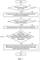
- the processor 650 may perform operations 710 to 760 shown in FIG. 7 .
- the processor 650 may detect the occurrence of a communication state change event.
- the communication state change event may be, for example, a case in which system power of the electronic device 600 is turned on, a case in which the electronic device 600 is connected to new communication, or a case in which a previously connected communication channel is changed.
- the processor 650 may set the spread spectrum method to the center-spread spectrum method in the SSCG 630 and set the spread ratio to a first spread ratio (e.g., a maximum spread ratio).
- a first spread ratio e.g., a maximum spread ratio
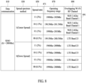
- data communication 810 of the electronic device 600 may be data communication according to an SDIO interface.
- the processor 650 may set a bit value for a spread spectrum method 830 in the first register 635 to "1" corresponding to the center-spread spectrum method and set a bit value for a spread ratio 850 in the first register 635 to "11" corresponding to the first spread ratio (e.g., 2%).
- the processor 650 may determine whether the electronic device 600 is connected to communication through the first communication module 610 or the second communication module 620.
- the first communication may be, for example, Wi-Fi communication
- the second communication may be, for example, RF communication for mobile communication (e.g., 4G and 5G).
- the processor 650 may maintain the center-spread spectrum method and the first spread ratio set to the SSCG 630.
- the SSCG 630 may generate and output a spread spectrum clock signal based on the center-spread spectrum method and the first spread ratio.
- the processor 650 may identify a frequency band of a channel of the connected communication. For example, a Wi-Fi channel frequency is known as shown in Table 1 below and an LTE channel frequency is known as shown in Table 2 below. According to an embodiment, when the connected communication channel is channel 1 of Wi-Fi 2.4 gigahertz (GHz), the processor 650 may confirm that a frequency of the communication channel connected to the electronic device 600 is 2.412 GHz with reference to Table 1.
- a Wi-Fi channel frequency is known as shown in Table 1 below and an LTE channel frequency is known as shown in Table 2 below.
- the processor 650 may confirm that a frequency of the communication channel connected to the electronic device 600 is 2.412 GHz with reference to Table 1.
- the processor 650 may determine whether a first frequency in a range of a first operating frequency and multiplication frequencies of the first frequency belong to a frequency band of a channel of connected communication.
- the range of the first operating frequency may be determined according to the center frequency f c , the center-spread spectrum method set to the SSCG 630, and the first spread ratio set to the SSCG 630.
- the data communication 810 may be data communication according to SDIO
- the center frequency may be 200 megahertz (MHz)
- the bit value for the spread spectrum method 830 in the first register 635 may be "1”
- the bit value for the spread ratio 850 in the first register 635 may be "11”.
- the processor 650 may determine the range of the first operating frequency of 198 MHz to 202 MHz according to f c - (f c ⁇ 1%) to f c + (f c ⁇ 1%).
- the processor 650 may determine whether the first frequency in 198 MHz to 202 MHz and the multiplication frequencies of the first frequency belong to a frequency band (e.g., 2.412 GHz band) of channel 1 of Wi-Fi 2.4 GHz. In an example, the processor 650 may confirm that 12 multiplication-frequency of 201 MHz in 198 MHz to 202 MHz belongs to the frequency band of channel 1 of Wi-Fi 2.4 GHz.
- a frequency band e.g., 2.412 GHz band
- the processor 650 may confirm that the first frequency in 198 MHz to 202 MHz and the multiplication frequencies of the first frequency do not belong to a frequency band of LTE band 21 (e.g., uplink band 1447.9 to 1462.9 and/or downlink band 1495.5 to 1510.9).
- a frequency band of LTE band 21 e.g., uplink band 1447.9 to 1462.9 and/or downlink band 1495.5 to 1510.9.
- the processor 650 may maintain the center-spread spectrum method and the first spread ratio set to the SSCG 630.
- the SSCG 630 may generate and output a spread spectrum clock signal based on the center-spread spectrum method and the first spread ratio.
- a wireless communication channel 890 overlapping with at least one of a frequency in a range of an operating frequency and multiplication frequencies may be predetermined in a lookup table (e.g., the lookup table of FIG. 8 ) stored in the memory 640 according to the type of the data communication 810, the center frequency, the spread spectrum method, and the spread ratio, for each operating frequency range 870.
- a lookup table e.g., the lookup table of FIG. 8
- the center frequency of 200 MHz, the spread spectrum bit value of "1”, and the spread ratio bit value of "11” the overlapping wireless communication channel may be determined as channel 1 891 of Wi-Fi 2.4 GHz band.
- the processor 650 may perform operation 920.
- the processor 650 may change the bit value for the spread spectrum method 830 in the first register 635 from “1" to "0".
- the processor 650 may determine whether at least one of a second frequency in a range of a second operating frequency and multiplication frequencies of the second frequency belongs to the frequency band of the connected wireless communication channel.
- the range of the second operating frequency may be determined according to the center frequency f c , the down-spread spectrum method set to the SSCG 630, and the first spread ratio set to the SSCG 630.
- the data communication 810 may be data communication according to SDIO
- the center frequency may be 200 MHz
- the bit value for the spread spectrum method 830 in the first register 635 may be "0”
- the bit value for the spread ratio 850 in the first register 635 may be "11”.
- the processor 650 may determine the range of the second operating frequency of 196 MHz to 200 MHz according to f 0 - (f 0 ⁇ 2%) to f 0 .
- the processor 650 may maintain the down-spread spectrum method and the first spread ratio set to the SSCG 630.
- the SSCG 630 may generate and output a spread spectrum clock signal based on the down-spread spectrum method and the first spread ratio.
- the processor 650 may confirm that 11 multiplication-frequency (2194.5 MHz) of a frequency of 199.5 MHz in the range of the second operating frequency of 196 MHz to 200 MHz belongs to the downlink band of 2180 MHz to 2200 MHz of LTE band 23.
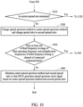
- the processor 650 may perform operation 1010 when at least one of the second frequency in the range of the second operating frequency and the multiplication frequencies of the second frequency belongs to the frequency band of the connected wireless communication channel.
- the processor 650 may determine whether the spread ratio set to the SSCG 630 is minimum. According to an embodiment, when the bit value for the spread ratio 850 in the first register 635 is "11", the processor 650 may confirm that the spread ratio set to the SSCG 630 is not minimum.
- the processor 650 may change the down-spread spectrum method set to the SSCG 630 to the center-spread spectrum method and change the first spread ratio (e.g., 2%) set to the SSCG 630 to a second spread ratio (e.g., 1.5%).
- the processor 650 may change the bit value for the spread spectrum method 830 of the first register 635 from “0” to “1” and change the bit value for the spread ratio 850 from "11" to "10".
- the range of the third operating frequency may be determined according to the center frequency f c , the center-spread spectrum method set to the SSCG 630, and the second spread ratio (e.g., 1.5%) set to the SSCG 630.
- the data communication 810 may be data communication according to SDIO
- the center frequency may be 200 MHz
- the bit value for the spread spectrum method 830 in the first register 635 may be "1”
- the bit value for the spread ratio 850 in the first register 635 may be "10".
- the processor 650 may determine the range of the third operating frequency of 198.5 MHz to 201.5 MHz according to f c - (f c ⁇ 0.75%) to f c + (f c ⁇ 0.75%).
- the processor 650 may maintain the center-spread spectrum method and the second spread ratio set to the SSCG 630.
- the SSCG 630 may generate and output a spread spectrum clock signal based on the center-spread spectrum method and the second spread ratio.
- the processor 650 may perform operation 920 when at least one of the third frequency in the third operating frequency and the multiplication frequencies of the third frequency belongs to the frequency band of the connected wireless communication channel.
- the processor 650 may change the center-spread spectrum method set to the SSCG 630 to the down-spectrum spread method.
- the processor 650 may change the bit value for the spread spectrum method 830 in the first register 635 from “1" to "0".
- the processor 650 may determine whether at least one of a fourth frequency in a range of a fourth operating frequency and multiplication frequencies of the fourth frequency belongs to the frequency band of the connected wireless communication channel.
- the range of the fourth operating frequency may be determined according to the center frequency f c , the down-spread spectrum method set to the SSCG 630, and the second spread ratio set to the SSCG 630.
- the data communication 810 may be data communication according to SDIO
- the center frequency may be 200 MHz
- the bit value for the spread spectrum method 830 in the first register 635 is "0”
- the bit value for the spread ratio 850 in the first register 635 may be "10".
- the processor 650 may determine the range of the fourth operating frequency of 197 MHz to 200 MHz according to f 0 - (f 0 ⁇ 1.5%) to f 0 .
- the processor 650 may maintain the down-spread spectrum method and the second spread ratio set to the SSCG 630.
- the SSCG 630 may generate and output a spread spectrum clock signal based on the down-spread spectrum method and the second spread ratio.
- the processor 650 may perform operation 1010 when at least one of the fourth frequency in the range of the fourth operating frequency and the multiplication frequencies of the fourth frequency belongs to the frequency band of the connected wireless communication channel.
- the processor 650 may repeat operations 1010, 1020, 1050, 920, and 950. Through this repetition, the down-spread spectrum method and the spread ratio of 0.5% may be set to the SSCG 630.
- the processor 650 may determine whether the spread ratio set to the SSCG 630 is minimum. As shown in FIG. 8 , since the spread ratio of 0.5% is a minimum spread ratio, the processor 650 may perform operation 1120.
- the processor 650 may change the down-spread spectrum method set to the SSCG 630 to the center-spread spectrum method and change the minimum spread ratio set to the SSCG 630 to a maximum spread ratio.
- the processor 650 since at least one of a frequency in a range of an operating frequency and multiplication frequencies determined according to all spread ratios supported by the center-spread spectrum method, the down-spread spectrum method, and a communication interface (e.g., the interface 177 of FIG. 1 ) belongs to the frequency band of the connected wireless communication, the processor 650, in operation 1120, may set the center-spread spectrum method and the maximum spread ratio to the SSCG 630.
- the SSCG 630 may generate and output a spread spectrum clock signal based on the center-spread spectrum method and the maximum spread ratio (e.g., a spread ratio of 2%).
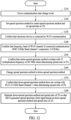
- FIG. 12 is a flowchart illustrating an operating method of an electronic device.
- a processor may detect the occurrence of a communication state change event.
- the communication state change event may be, for example, a case in which system power of an electronic device (e.g., 600 of FIG. 6 ) is turned on, a case in which an electronic device is connected to new communication, or a case in which a previously connected communication channel is changed.
- a processor may set the spread spectrum method to the center-spread spectrum method in an SSCG (e.g., 630 in FIG. 6 ) and set the spread ratio to the first spread ratio (e.g., the maximum spread ratio).
- data communication e.g., 810 in FIG. 8
- an electronic device e.g., 600 in FIG. 6
- a processor may set a bit value (e.g., 830 of FIG.
- a first register e.g., 635 in FIG. 6
- a bit value e.g., 850 in FIG. 8
- the spread ratio in the first register e.g., 635 in FIG. 6
- a bit value e.g., 850 in FIG. 8
- a processor may confirm that an electronic device (600 in FIG. 6 ) is connected to communication through a first communication module (e.g., 610 of FIG. 6 ) or a second communication module (e.g., 620 of FIG. 6 ).
- the first communication may be, for example, Wi-Fi communication and the second communication may be, for example, RF communication for mobile communication (e.g., 4G and 5G).
- a processor e.g., 650 of FIG. 6
- a processor may identify a frequency band of a channel of connected communication. For example, in operation 1240, when the connected communication channel is channel 1 of Wi-Fi 2.4 GHz, a processor (e.g., 650 of FIG. 6 ) may confirm that a frequency of the communication channel connected to an electronic device (e.g., 600 of FIG. 6 ) is 2.412 GHz with reference to Table 1.
- a processor may determine whether the first frequency in the range of the first operating frequency and the multiplication frequencies of the first frequency belong to the frequency band of the connected communication channel.
- the range of the first operating frequency may be determined according to the center frequency f c , the center-spread spectrum method set to an SSCG (e.g., 630 in FIG. 6 ), and the first spread ratio set to an SSCG (e.g., 630 in FIG. 6 ), and data communication (e.g., 810 in FIG. 8 ) may be data communication according to SDIO, the center frequency may be 200 MHz, a bit value (e.g., 830 in FIG.
- a processor e.g., 650 in FIG. 6 may determine the range of the first operating frequency of 198 MHz to 202 MHz according to f c - (f c ⁇ 1%) to f c + (f c ⁇ 1%).
- a processor may determine whether the first frequency in 198 MHz to 202 MHz and the multiplication frequencies of the first frequency belong to the frequency band (e.g., 2.412 GHz band) of channel 1 of Wi-Fi 2.4 GHz. In an example, a processor (e.g., 650 in FIG. 6 ) may confirm that 12 multiplication-frequency of 201 MHz in 198 MHz to 202 MHz belongs to the frequency band of channel 1 of Wi-Fi 2.4 GHz.
- a processor e.g., 650 of FIG. 6
- the processor in operation 1260, may change the center-spread spectrum method set to an SSCG (e.g., 630 of FIG. 6 ) to the down-spread spectrum method.
- a processor e.g., 650 of FIG. 6
- may change a bit value e.g., 830 of FIG. 8
- a first register e.g., 635 of FIG. 6
- a processor e.g., 650 of FIG. 6 may determine whether at least one of the second frequency in the range of the second operating frequency and the multiplication frequencies of the second frequency belongs to the frequency band of the wireless communication channel.
- a processor may confirm that the second frequency in the range of the second operating frequency of 196 MHz to 200 MHz and the multiplication frequencies of the second frequency do not belong to the frequency band of channel 1 of the connected wireless communication channel of Wi-Fi 2.4 GHz.
- the processor 650 when a communication state change event of the electronic device 600 occurs, may set the spread spectrum method and the spread ratio to the first spread spectrum method and the first spread ratio to the SSCG, respectively, and may determine whether the electronic device 600 is connected to the first wireless communication and the second wireless communication, when the electronic device 600 is connected to at least one of the first wireless communication and the second wireless communication, may identify the frequency band of the channel of connected wireless communication and determine whether at least one of the first frequency in the range of the first operating frequency and the multiplication frequencies of the first frequency belongs to the frequency band of the channel, and when the first frequency and the multiplication frequencies of the first frequency do not belong to the frequency band, may maintain the first spread spectrum method and the first spread ratio so that the SSCG 630 generates the spread spectrum clock signal based on the first spread spectrum method and the first spread ratio.
- the range of the first operating frequency may be determined based on the center frequency of data communication, the first spread spectrum method, and the first spread ratio.
- the processor 650 when at least one of the first frequency and the multiplication frequencies of the first frequency belongs to the frequency band of the connected wireless communication channel, may change the first spread spectrum method to the second spread spectrum method and determine whether at least one of the second frequency in the range of the second operating frequency and the multiplication frequencies of the second frequency belongs to the frequency band of the connected wireless communication channel.
- the processor 650 may maintain the second spread spectrum method and the first spread ratio and the SSCG 630 may generate the spread spectrum clock signal based on the second spread spectrum method and the first spread ratio.
- the processor 650 when at least one of the second frequency and the multiplication frequencies of the second frequency belongs to the frequency band of the connected wireless communication channel, may determine whether the first spread ratio is minimum, and when the first spread ratio is not minimum, may change the second spread spectrum method to the first spread spectrum method and may change the first spread ratio to the second spread ratio.
- the processor 650 may determine whether at least one of the third frequency in the range of the third operating frequency and the multiplication frequencies of the third frequency belongs to the frequency band.
- the range of the third operating frequency may be determined based on the center frequency of data communication, the first spread spectrum method, and the second spread ratio.
- the processor 650 may change the first spread spectrum method to the second spread spectrum method and may determine whether at least one of the fourth frequency in the range of the fourth operating frequency and the multiplication frequencies of the fourth frequency belongs to the frequency band of the connected wireless communication channel.
- the processor 650 may set a bit value corresponding to the first spread spectrum method and a bit value corresponding to the first spread ratio to the first register 635 in the SSCG 630.
- the first wireless communication may be Wi-Fi communication and the second wireless communication may be RF communication.
- the first spread spectrum method may include the spread spectrum method.
- the electronic device 600 may include the first communication module 610 for the first wireless communication, the second communication module 620 for the second wireless communication, the SSCG 630 that generates the spread spectrum clock signal for data communication of the electronic device 600, the processor 650, and the memory 640.
- the processor 650 may set the spread spectrum method and the spread ratio to the first spread spectrum method and the first spread ratio in the SSCG 630, respectively, when the electronic device 600 is connected to at least one of the first wireless communication and the second wireless communication, may determine whether at least one of the first frequency in the range of the first operating frequency and the multiplication frequencies of the first frequency belongs to the frequency band of the connected wireless communication channel, and when at least one of the first frequency and the multiplication frequencies of the first frequency belongs to the frequency band, may change the first spread spectrum method set to the SSCG 630 to the second spread spectrum method and may determine whether at least one of the second frequency in the range of the second operating frequency and the multiplication frequencies of the second frequency belongs to the frequency band.
- the range of the first operating frequency may be determined based on the center frequency of data communication, the first spread spectrum method, and the first spread ratio.
- the range of the second operating frequency may be determined based on the center frequency of data communication, the second spread spectrum method, and the first spread ratio.
- the memory 640 may store a lookup table used to determine whether at least one of a frequency in a range of an operating frequency and multiplication frequencies of the frequency of a clock signal belongs to the frequency band of the connected wireless communication channel.
- the processor 650 may change the second spread spectrum method to the first spread spectrum method, change the first spread ratio to the second spread ratio, and determine whether at least one of the third frequency in the range of the third operating frequency and the multiplication frequencies of the third frequency belongs to the frequency band.
- the range of the third operating frequency may be determined based on the center frequency of data communication, the first spread spectrum method, and the second spread ratio.
- the processor 650 may change the first spread spectrum method to the second spread spectrum method and determine whether at least one of the fourth frequency in the range of the fourth operating frequency and the multiplication frequencies of the fourth frequency belongs to the frequency band.
- the range of the fourth operating frequency may be determined based on the center frequency of data communication, the second spread spectrum method, and the second spread ratio.
- the processor 650 may maintain the first spread spectrum method and the first spread ratio so that the SSCG 630 generates the spread spectrum clock signal based on the first spread spectrum method and the first spread ratio.
- the processor 650 may maintain the second spread spectrum method and the first spread ratio so that the SSCG 630 generates the spread spectrum clock signal based on the second spread spectrum method and the first spread ratio.
- the processor 650 may maintain the first spread spectrum method and the second spread ratio so that the SSCG 630 generates the spread spectrum clock signal based on the first spread spectrum method and the second spread ratio.
- the processor 650 may maintain the second spread spectrum method and the second spread ratio so that the SSCG 630 generates the spread spectrum clock signal based on the second spread spectrum method and the second spread ratio.
- the processor 650 may change the spread spectrum method and spread ratio to the center-spread spectrum method and the maximum spread ratio in the SSCG 630, respectively, and maintain the center-spread spectrum method and the maximum spread ratio so that the SSCG 630 generates the spread spectrum clock signal based on the center-spread spectrum method and the maximum spread ratio.
- the method of operating the electronic device 600 may include operation 710 of detecting the occurrence of the communication state change event of the electronic device 600, operation 720 of setting the spread spectrum method and the spread ratio to the first spread spectrum method and the first spread ratio in the spread spectrum clock signal generator 630 for data communication of the electronic device 600, respectively, operation 730 of determining whether the electronic device 600 is connected to the first wireless communication and the second wireless communication, operation 740 of identifying the frequency band of the channel of connected wireless communication when the electronic device 600 is connected to at least one of the first communication and the second wireless communication, operation 750 of determining whether at least one of the first frequency in the range of the first operating frequency and the multiplication frequencies of the first frequency belongs to the frequency band of the connected wireless communication channel, and when the first frequency and the multiplication frequencies of the first frequency do not belong to the frequency band of the connected wireless communication channel, operation 760 of maintaining the first spread spectrum method and the first spread ratio so that the SSCG 630 generates the spread spectrum clock signal based on the first spread spectrum method and the first spread ratio
- the range of the first operating frequency may be determined based on the center frequency of data communication, the first spread spectrum method, and the first spread ratio.
- the method of operating the electronic device 600 may further include, when at least one of the first frequency and the multiplication frequencies of the first frequency belongs to the frequency band of the connected wireless communication channel, operation 920 of changing the first spread spectrum method to the second spread spectrum method and operation 950 of determining whether at least one of the second frequency in the range of the second operating frequency and the multiplication frequencies of the second frequency belongs to the frequency band of the connected wireless communication channel.
- the range of the second operating frequency may be determined based on the center frequency of data communication, the second spread spectrum method, and the first spread ratio.
- the method of operating the electronic device 600 when the second frequency and the multiplication frequencies of the second frequency do not belong to the frequency band, may further include operation 960 of maintaining the second spread spectrum method and the first spread ratio so that the SSCG 630 generates the spread spectrum clock signal based on the second spread spectrum method and the first spread ratio.
- the method of operating the electronic device 600 when at least one of the second frequency and the multiplication frequencies of the second frequency belongs to the frequency band, may further include operation 1010 of determining whether the first spread ratio is minimum, and when the first spread ratio is not minimum, may further include operation 1020 of changing the second spread spectrum method to the first spread spectrum method and changing the first spread ratio to the second spread ratio.
- the method of operating the electronic device 600 may further include operation 1050 of determining whether at least one of the third frequency in the range of the third operating frequency and the multiplication frequencies of the third frequency belongs to the frequency band.
- the range of the third operating frequency may be determined based on the center frequency of data communication, the first spread spectrum method, and the second spread ratio.
- the method of operating the electronic device 600 when the third frequency and the multiplication frequencies of the third frequency do not belong to the frequency band, may further include operation 1060 of maintaining the first spread spectrum method and the second spread ratio so that the SSCG 630 generates the spread spectrum clock signal based on the first spread spectrum method and the second spread ratio.
- the method of operating the electronic device 600 when the first spread ratio is minimum, may further include operation 1120 of changing the spread spectrum method to the center-spread spectrum method and changing the spread ratio to the maximum spread ratio.
- the method of operating the electronic device 600 may further include operation 1160 of maintaining the center-spread spectrum method and the maximum spread ratio so that the SSCG 630 generates the spread spectrum clock signal based on the center-spread spectrum method and the maximum spread ratio.
Landscapes
- Engineering & Computer Science (AREA)
- Signal Processing (AREA)
- Computer Networks & Wireless Communication (AREA)
- Mobile Radio Communication Systems (AREA)
Claims (13)
- Elektronische Vorrichtung (600), umfassend:ein erstes Kommunikationsmodul (610) für die erste drahtlose Kommunikation;ein zweites Kommunikationsmodul (620) für die zweite drahtlose Kommunikation;einen Streuspektrum-Taktgeber, SSCG (630), der konfiguriert ist, um ein Streuspektrum-Taktsignal für die Datenkommunikation der elektronischen Vorrichtung (600) zu erzeugen; undeinen Prozessor (650),dadurch gekennzeichnet, dass der Prozessor (650) konfiguriert ist zum,wenn ein Kommunikationszustandsänderungsereignis der elektronischen Vorrichtung (600) auftritt, Einstellen eines Streuspektrumverfahrens und eines Streuverhältnisses auf ein erstes Streuspektrumverfahren bzw. ein erstes Streuverhältnis in dem SSCG (630) und Bestimmen, ob die elektronische Vorrichtung (600) mit der ersten drahtlosen Kommunikation und der zweiten drahtlosen Kommunikation verbunden ist;wenn die elektronische Vorrichtung (600) mit mindestens einer der ersten drahtlosen Kommunikation und der zweiten drahtlosen Kommunikation verbunden ist, Identifizieren eines Frequenzbandes eines Kanals der verbundenen drahtlosen Kommunikation und Bestimmen, ob mindestens eine von einer ersten Frequenz in einem Bereich einer ersten Betriebsfrequenz und von Multiplikationsfrequenzen der ersten Frequenz zu dem Frequenzband des Kanals gehört;wenn die erste Frequenz und die Multiplikationsfrequenzen der ersten Frequenz nicht zum Frequenzband gehören, Beibehalten des ersten Streuspektrumverfahrens und des ersten Streuverhältnisses, so dass der SSCG (630) das Streuspektrum-Taktsignal basierend auf dem ersten Streuspektrumverfahren und dem ersten Streuverhältnis erzeugt, wobei der Bereich der ersten Betriebsfrequenz basierend auf einer Mittenfrequenz der Datenkommunikation, dem ersten Streuspektrumverfahren und dem ersten Streuverhältnis bestimmt wird; undwenn mindestens eine der ersten Frequenz und der Multiplikationsfrequenzen der ersten Frequenz zu dem Frequenzband gehört, Ändern des ersten Streuspektrumverfahrens, das auf den SSCG (630) eingestellt ist, in ein zweites Streuspektrumverfahren und Bestimmen, ob mindestens eine einer zweiten Frequenz in einem Bereich einer zweiten Betriebsfrequenz und von Multiplikationsfrequenzen der zweiten Frequenz zu dem Frequenzband gehört, wobei der Bereich der zweiten Betriebsfrequenz basierend auf der Mittenfrequenz, dem zweiten Streuspektrumverfahren und dem ersten Streuverhältnis bestimmt wird.
- Elektronische Vorrichtung (600) nach Anspruch 1, wobeider Prozessor (650) konfiguriert ist, um das zweite Streuspektrumverfahren und das erste Streuverhältnis beizubehalten, wenn die zweite Frequenz und die Multiplikationsfrequenzen der zweiten Frequenz nicht zu dem Frequenzband gehören, undder SSCG (630) konfiguriert ist, um ein Streuspektrum-Taktsignal basierend auf dem zweiten Streuspektrumverfahren und dem ersten Streuverhältnis zu erzeugen.
- Elektronische Vorrichtung (600) nach Anspruch 1, wobei der Prozessor (650) konfiguriert ist, um, wenn mindestens eine der zweiten Frequenz und der Multiplikationsfrequenzen der zweiten Frequenz zu dem Frequenzband gehört, zu bestimmen, ob das erste Streuverhältnis minimal ist, und wenn das erste Streuverhältnis nicht minimal ist, das zweite Streuspektrumverfahren in das erste Streuspektrumverfahren zu ändern und das erste Streuverhältnis in ein zweites Streuverhältnis zu ändern.
- Elektronische Vorrichtung (600) nach Anspruch 3, wobei der Prozessor (650) konfiguriert ist, um zu bestimmen, ob mindestens eine von einer dritten Frequenz in einem Bereich einer dritten Betriebsfrequenz und Multiplikationsfrequenzen der dritten Frequenz zu dem Frequenzband gehört,
wobei der Bereich der dritten Betriebsfrequenz basierend auf der Mittenfrequenz, dem ersten Streuspektrumverfahren und dem zweiten Streuverhältnis bestimmt wird. - Elektronische Vorrichtung (600) nach Anspruch 4, wobei der Prozessor (650) konfiguriert ist, um, wenn mindestens eine der dritten Frequenz und der Multiplikationsfrequenzen der dritten Frequenz zu dem Frequenzband gehört, das erste Streuspektrumverfahren in ein zweites Streuspektrumverfahren zu ändern und zu bestimmen, ob mindestens eine von einer vierten Frequenz in einem Bereich einer vierten Betriebsfrequenz und von Multiplikationsfrequenzen der vierten Frequenz zu dem Frequenzband gehört,
wobei der Bereich der vierten Betriebsfrequenz basierend auf der Mittenfrequenz, dem zweiten Streuspektrumverfahren und dem zweiten Streuverhältnis bestimmt wird. - Elektronische Vorrichtung (600) nach Anspruch 1, wobei der Prozessor (650) konfiguriert ist, um einen Bitwert, der dem ersten Streuspektrumverfahren entspricht, und einen Bitwert, der dem ersten Streuverhältnis entspricht, in ein erstes Register (635) im SSCG (630) festzulegen.
- Elektronische Vorrichtung (600) nach Anspruch 1, wobeidie erste drahtlose Kommunikation eine Wireless Fidelity-, Wi-Fi-,Kommunikation ist, unddie zweite drahtlose Kommunikation eine Hochfrequenz-, HF-,Kommunikation ist.
- Elektronische Vorrichtung (600) nach Anspruch 1, wobei das erste Streuspektrumverfahren ein Mittenstreuspektrumverfahren umfasst.
- Verfahren zum Betreiben einer elektronischen Vorrichtung (600), wobei das Verfahren, wenn ein Kommunikationszustandsänderungsereignis der elektronischen Vorrichtung (600) auftritt, Folgendes umfasstEinstellen eines Streuspektrumverfahrens und eines Streuverhältnisses auf ein erstes Streuspektrumverfahren und ein erstes Streuverhältnis in einem Streuspektrum-Taktgenerator, SSCG (630), für die Datenkommunikation der elektronischen Vorrichtung (600), bzw.;Bestimmen, ob die elektronische Vorrichtung (600) mit der ersten drahtlosen Kommunikation und der zweiten drahtlosen Kommunikation verbunden ist;Identifizieren eines Frequenzbandes eines Kanals der verbundenen drahtlosen Kommunikation, wenn die elektronische Vorrichtung (600) mit mindestens einer der ersten drahtlosen Kommunikation und der zweiten drahtlosen Kommunikation verbunden ist;Bestimmen, ob mindestens eine von einer ersten Frequenz in einem Bereich einer ersten Betriebsfrequenz und von Multiplikationsfrequenzen der ersten Frequenz zum Frequenzband des Kanals gehört;Beibehalten des ersten Streuspektrumverfahrens und des ersten Streuverhältnisses, so dass der SSCG (630) das Streuspektrum-Taktsignal basierend auf dem ersten Streuspektrumverfahren und dem ersten Streuverhältnis erzeugt, wenn die erste Frequenz und die Multiplikationsfrequenzen der ersten Frequenz nicht zu dem Frequenzband gehören, wobei der Bereich der ersten Betriebsfrequenz basierend auf einer Mittenfrequenz der Datenkommunikation, dem ersten Streuspektrumverfahren und dem ersten Streuverhältnis bestimmt wird; undwenn mindestens eine der ersten Frequenz und der Multiplikationsfrequenzen der ersten Frequenz zu dem Frequenzband gehört, Ändern des ersten Streuspektrumverfahrens, das auf den SSCG (630) eingestellt ist, in ein zweites Streuspektrumverfahren und Bestimmen, ob mindestens eine einer zweiten Frequenz in einem Bereich einer zweiten Betriebsfrequenz und von Multiplikationsfrequenzen der zweiten Frequenz zu dem Frequenzband gehört, wobei der Bereich der zweiten Betriebsfrequenz basierend auf der Mittenfrequenz, dem zweiten Streuspektrumverfahren und dem ersten Streuverhältnis bestimmt wird.
- Verfahren nach Anspruch 9, ferner umfassend,
wenn die zweite Frequenz und die Multiplikationsfrequenzen der zweiten Frequenz nicht zum Frequenzband gehören, Beibehalten des zweiten Streuspektrumverfahrens und des ersten Streuverhältnisses, so dass der SSCG (630) das Streuspektrum-Taktsignal basierend auf dem zweiten Streuspektrumverfahren und dem ersten Streuverhältnis erzeugt. - Verfahren nach Anspruch 9, ferner umfassend,
wenn mindestens eine der zweiten Frequenz und der Multiplikationsfrequenzen der zweiten Frequenz zu dem Frequenzband gehört, Bestimmen ob das erste Streuverhältnis minimal ist, und wenn das erste Streuverhältnis nicht minimal ist, Ändern des zweiten Streuspektrumverfahrens in das erste Streuspektrumverfahren und Ändern des ersten Streuverhältnisses in ein zweites Streuverhältnis. - Verfahren nach Anspruch 11, ferner umfassend:Bestimmen, ob mindestens eine von einer dritten Frequenz in einem Bereich einer dritten Betriebsfrequenz und von Multiplikationsfrequenzen der dritten Frequenz zum Frequenzband gehört;wobei der Bereich der dritten Betriebsfrequenz basierend auf der Mittenfrequenz, dem ersten Streuspektrumverfahren und dem zweiten Streuverhältnis bestimmt wird.
- Verfahren nach Anspruch 12, ferner umfassend,wenn mindestens eine der dritten Frequenz und der Multiplikationsfrequenzen der dritten Frequenz zu dem Frequenzband gehört, Ändern des ersten Streuspektrumverfahrens in ein zweites Streuspektrumverfahren und Bestimmen, ob mindestens eine einer vierten Frequenz in einem Bereich einer vierten Betriebsfrequenz und der Multiplikationsfrequenzen der vierten Frequenz zu dem Frequenzband gehört,wobei der Bereich der vierten Betriebsfrequenz basierend auf der Mittenfrequenz, dem zweiten Streuspektrumverfahren und dem zweiten Streuverhältnis bestimmt wird.
Applications Claiming Priority (2)
| Application Number | Priority Date | Filing Date | Title |
|---|---|---|---|
| KR1020210004595A KR20220102347A (ko) | 2021-01-13 | 2021-01-13 | 전자 장치 및 이의 동작 방법 |
| PCT/KR2022/000288 WO2022154385A1 (ko) | 2021-01-13 | 2022-01-07 | 전자 장치 및 이의 동작 방법 |
Publications (3)
| Publication Number | Publication Date |
|---|---|
| EP4236114A1 EP4236114A1 (de) | 2023-08-30 |
| EP4236114A4 EP4236114A4 (de) | 2024-06-26 |
| EP4236114B1 true EP4236114B1 (de) | 2025-03-05 |
Family
ID=82448388
Family Applications (1)
| Application Number | Title | Priority Date | Filing Date |
|---|---|---|---|
| EP22739583.7A Active EP4236114B1 (de) | 2021-01-13 | 2022-01-07 | Elektronische vorrichtung und betriebsverfahren dafür |
Country Status (4)
| Country | Link |
|---|---|
| US (1) | US12231271B2 (de) |
| EP (1) | EP4236114B1 (de) |
| KR (1) | KR20220102347A (de) |
| WO (1) | WO2022154385A1 (de) |
Family Cites Families (23)
| Publication number | Priority date | Publication date | Assignee | Title |
|---|---|---|---|---|
| JP2000341165A (ja) | 1999-05-25 | 2000-12-08 | Matsushita Electric Ind Co Ltd | 通信装置、通信方法および記録媒体 |
| JP2001217743A (ja) * | 2000-01-31 | 2001-08-10 | Matsushita Electric Ind Co Ltd | データ通信装置 |
| JP4119696B2 (ja) | 2001-08-10 | 2008-07-16 | 松下電器産業株式会社 | 送信装置、受信装置及び無線通信方法 |
| ES2885101T3 (es) | 2004-01-29 | 2021-12-13 | Neo Wireless Llc | Procedimientos y aparatos para superponer señales de espectro ensanchado de secuencia directa y de múltiples portadoras en un sistema de comunicación inalámbrica de banda ancha |
| US7643534B2 (en) * | 2005-10-26 | 2010-01-05 | Kyocera Mita Corporation | Clock signal controlling device |
| US7590163B1 (en) * | 2006-05-19 | 2009-09-15 | Conexant Systems, Inc. | Spread spectrum clock generation |
| US8312310B2 (en) * | 2007-05-01 | 2012-11-13 | Canon Kabushiki Kaisha | Apparatus and method for changing clock frequency and modulation method based on current state |
| KR100792042B1 (ko) | 2007-05-30 | 2008-01-04 | 인하대학교 산학협력단 | 확산 스펙트럼 클럭 발생기 |
| KR101105690B1 (ko) | 2008-03-03 | 2012-01-17 | 닛본 덴끼 가부시끼가이샤 | 무선 기지국 및 송신 전력 결정 방법 |
| EP2224606B1 (de) | 2009-02-27 | 2012-10-03 | Research In Motion Limited | Verfahren und System zur Charakterisierung eines Funkkanals eines drahtlosen Netzwerks mithilfe der Variabilität der Synchronisation |
| WO2011014178A1 (en) | 2009-07-31 | 2011-02-03 | Hewlett-Packard Development Company, L.P. | Providing fault-tolerant spread spectrum clock signals in a system |
| KR101135872B1 (ko) | 2009-08-06 | 2012-04-19 | 주식회사 실리콘웍스 | 스프레드 스펙트럼 클럭 발생기 |
| JP2011135262A (ja) | 2009-12-24 | 2011-07-07 | Canon Finetech Inc | クロック信号制御装置および画像形成装置 |
| US8406722B2 (en) * | 2011-02-28 | 2013-03-26 | Psion Inc. | Channel reception characteristics through clock rate adjustment |
| JP5696777B2 (ja) * | 2011-03-01 | 2015-04-08 | 富士通株式会社 | クロックジェネレータ及びそれを含むシステム |
| US9238580B2 (en) | 2013-03-11 | 2016-01-19 | Analog Devices Global | Spread-spectrum MEMS self-test system and method |
| US9048851B2 (en) | 2013-03-15 | 2015-06-02 | Intel Corporation | Spread-spectrum apparatus for voltage regulator |
| JP6396675B2 (ja) | 2014-05-12 | 2018-09-26 | Necプラットフォームズ株式会社 | 無線装置、無線通信システムおよび無線通信方法 |
| KR20150134484A (ko) * | 2014-05-21 | 2015-12-02 | 삼성디스플레이 주식회사 | 무선 통신 장치 및 무선 통신 장치에 포함되는 디스플레이 장치의 구동 방법 |
| JP6556889B2 (ja) | 2017-03-17 | 2019-08-07 | アンリツ株式会社 | スペクトラム拡散クロック発生器及びスペクトラム拡散クロック発生方法とパターン発生器及びパターン発生方法 |
| WO2018225624A1 (ja) * | 2017-06-06 | 2018-12-13 | キヤノン株式会社 | 無線通信装置およびその制御方法 |
| KR102484873B1 (ko) | 2017-12-06 | 2023-01-05 | 엘지디스플레이 주식회사 | 확산 스펙트럼 클럭 발생기, 확산 스펙트럼 클럭 발생 방법 및 이를 이용한 표시장치와 터치 표시장치 |
| KR102371668B1 (ko) | 2018-02-06 | 2022-03-08 | 삼성전자주식회사 | 신호의 emi를 감소시키는 집적 회로, 방법 및 전자 장치 |
-
2021
- 2021-01-13 KR KR1020210004595A patent/KR20220102347A/ko active Pending
-
2022
- 2022-01-07 EP EP22739583.7A patent/EP4236114B1/de active Active
- 2022-01-07 WO PCT/KR2022/000288 patent/WO2022154385A1/ko not_active Ceased
-
2023
- 2023-07-13 US US18/221,717 patent/US12231271B2/en active Active
Also Published As
| Publication number | Publication date |
|---|---|
| EP4236114A1 (de) | 2023-08-30 |
| EP4236114A4 (de) | 2024-06-26 |
| WO2022154385A1 (ko) | 2022-07-21 |
| US12231271B2 (en) | 2025-02-18 |
| US20230362043A1 (en) | 2023-11-09 |
| KR20220102347A (ko) | 2022-07-20 |
Similar Documents
| Publication | Publication Date | Title |
|---|---|---|
| US12550067B2 (en) | Electronic device for adjusting transmission rate and operation method therefor | |
| US12149648B2 (en) | Electronic device and prevention method for preventing deterioration by operation of antenna module | |
| US20250286577A1 (en) | Method for reducing vco coupling and electronic device supporting same | |
| US12585369B2 (en) | Electronic device including multi-channel grip sensor, and method for sensing capacitance change using multi-channel grip sensor | |
| US20250105850A1 (en) | Wireless communication device and method for controlling activation of rf transmission signal generation circuit | |
| US20240276402A1 (en) | Electronic device comprising multi-sim | |
| EP4236114B1 (de) | Elektronische vorrichtung und betriebsverfahren dafür | |
| US12597960B2 (en) | Electronic device and harmonic control method of electronic device | |
| US12574058B2 (en) | Multiplexer and electronic device containing multiplexer | |
| US20230156613A1 (en) | Method of controlling power supply for amplifying radio frequency signal and communication apparatus for performing the same | |
| US12512860B2 (en) | Electronic device for controlling switch electrically connected to antenna and operation method for electronic device | |
| US12185253B2 (en) | Electronic device and method for adjusting output power of radio frequency signal to be output to antenna | |
| US20260101288A1 (en) | Method for controlling transmission power of satellite communication, and electronic device therefor | |
| US20230345443A1 (en) | Electronic device including antenna module in communication system, and method of operating same | |
| EP4521654A1 (de) | Elektronische vorrichtung und sendeantennenauswahlverfahren dafür | |
| US12292776B2 (en) | Electronic device including sensor and method for operating the same | |
| US20250227629A1 (en) | Method for controlling antenna configuration in electronic device comprising plurality of antennas, and electronic device supporting same | |
| US20250175909A1 (en) | Method for controlling transmission power of wireless communication, and electronic device using method | |
| EP4716101A1 (de) | Elektronische vorrichtung zum wechseln einer übertragungsantenne und verfahren zum betrieb davon | |
| EP4567558A1 (de) | Verfahren zur steuerung einer elektronischen vorrichtung auf temperaturbasis und elektronische vorrichtung dafür | |
| US20260032606A1 (en) | Electronic device and method for changing transmission antenna path using same | |
| US20240204820A1 (en) | Electronic device for controlling output of power amplifier | |
| KR20240170345A (ko) | 안테나와 인접한 카메라를 제어하는 전자 장치 및 전자 장치의 동작 방법 | |
| EP4279952A1 (de) | Elektronische vorrichtung zur bestimmung der position einer externen elektronischen vorrichtung und betriebsverfahren einer elektronischen vorrichtung | |
| KR20240143555A (ko) | 안테나와 전기적으로 연결된 스위치를 제어하는 전자 장치 및 전자 장치의 동작 방법 |
Legal Events
| Date | Code | Title | Description |
|---|---|---|---|
| STAA | Information on the status of an ep patent application or granted ep patent |
Free format text: STATUS: THE INTERNATIONAL PUBLICATION HAS BEEN MADE |
|
| PUAI | Public reference made under article 153(3) epc to a published international application that has entered the european phase |
Free format text: ORIGINAL CODE: 0009012 |
|
| STAA | Information on the status of an ep patent application or granted ep patent |
Free format text: STATUS: REQUEST FOR EXAMINATION WAS MADE |
|
| 17P | Request for examination filed |
Effective date: 20230524 |
|
| AK | Designated contracting states |
Kind code of ref document: A1 Designated state(s): AL AT BE BG CH CY CZ DE DK EE ES FI FR GB GR HR HU IE IS IT LI LT LU LV MC MK MT NL NO PL PT RO RS SE SI SK SM TR |
|
| DAV | Request for validation of the european patent (deleted) | ||
| DAX | Request for extension of the european patent (deleted) | ||
| A4 | Supplementary search report drawn up and despatched |
Effective date: 20240524 |
|
| RIC1 | Information provided on ipc code assigned before grant |
Ipc: H04B 1/707 20110101ALI20240517BHEP Ipc: H04B 15/02 20060101AFI20240517BHEP |
|
| GRAP | Despatch of communication of intention to grant a patent |
Free format text: ORIGINAL CODE: EPIDOSNIGR1 |
|
| STAA | Information on the status of an ep patent application or granted ep patent |
Free format text: STATUS: GRANT OF PATENT IS INTENDED |
|
| INTG | Intention to grant announced |
Effective date: 20241029 |
|
| RIN1 | Information on inventor provided before grant (corrected) |
Inventor name: YOON, SEUNGJOON Inventor name: LEE, CHEOLHO Inventor name: KIM, DUCKJIN |
|
| GRAS | Grant fee paid |
Free format text: ORIGINAL CODE: EPIDOSNIGR3 |
|
| GRAA | (expected) grant |
Free format text: ORIGINAL CODE: 0009210 |
|
| STAA | Information on the status of an ep patent application or granted ep patent |
Free format text: STATUS: THE PATENT HAS BEEN GRANTED |
|
| AK | Designated contracting states |
Kind code of ref document: B1 Designated state(s): AL AT BE BG CH CY CZ DE DK EE ES FI FR GB GR HR HU IE IS IT LI LT LU LV MC MK MT NL NO PL PT RO RS SE SI SK SM TR |
|
| REG | Reference to a national code |
Ref country code: GB Ref legal event code: FG4D |
|
| REG | Reference to a national code |
Ref country code: CH Ref legal event code: EP |
|
| REG | Reference to a national code |
Ref country code: DE Ref legal event code: R096 Ref document number: 602022011502 Country of ref document: DE |
|
| REG | Reference to a national code |
Ref country code: IE Ref legal event code: FG4D |
|
| PG25 | Lapsed in a contracting state [announced via postgrant information from national office to epo] |
Ref country code: RS Free format text: LAPSE BECAUSE OF FAILURE TO SUBMIT A TRANSLATION OF THE DESCRIPTION OR TO PAY THE FEE WITHIN THE PRESCRIBED TIME-LIMIT Effective date: 20250605 |
|
| PG25 | Lapsed in a contracting state [announced via postgrant information from national office to epo] |
Ref country code: FI Free format text: LAPSE BECAUSE OF FAILURE TO SUBMIT A TRANSLATION OF THE DESCRIPTION OR TO PAY THE FEE WITHIN THE PRESCRIBED TIME-LIMIT Effective date: 20250305 |
|
| REG | Reference to a national code |
Ref country code: NL Ref legal event code: MP Effective date: 20250305 |
|
| PG25 | Lapsed in a contracting state [announced via postgrant information from national office to epo] |
Ref country code: ES Free format text: LAPSE BECAUSE OF FAILURE TO SUBMIT A TRANSLATION OF THE DESCRIPTION OR TO PAY THE FEE WITHIN THE PRESCRIBED TIME-LIMIT Effective date: 20250305 |
|
| REG | Reference to a national code |
Ref country code: LT Ref legal event code: MG9D |
|
| PG25 | Lapsed in a contracting state [announced via postgrant information from national office to epo] |
Ref country code: NO Free format text: LAPSE BECAUSE OF FAILURE TO SUBMIT A TRANSLATION OF THE DESCRIPTION OR TO PAY THE FEE WITHIN THE PRESCRIBED TIME-LIMIT Effective date: 20250605 |
|
| PG25 | Lapsed in a contracting state [announced via postgrant information from national office to epo] |
Ref country code: HR Free format text: LAPSE BECAUSE OF FAILURE TO SUBMIT A TRANSLATION OF THE DESCRIPTION OR TO PAY THE FEE WITHIN THE PRESCRIBED TIME-LIMIT Effective date: 20250305 |
|
| PG25 | Lapsed in a contracting state [announced via postgrant information from national office to epo] |
Ref country code: LV Free format text: LAPSE BECAUSE OF FAILURE TO SUBMIT A TRANSLATION OF THE DESCRIPTION OR TO PAY THE FEE WITHIN THE PRESCRIBED TIME-LIMIT Effective date: 20250305 |
|
| PG25 | Lapsed in a contracting state [announced via postgrant information from national office to epo] |
Ref country code: GR Free format text: LAPSE BECAUSE OF FAILURE TO SUBMIT A TRANSLATION OF THE DESCRIPTION OR TO PAY THE FEE WITHIN THE PRESCRIBED TIME-LIMIT Effective date: 20250606 Ref country code: BG Free format text: LAPSE BECAUSE OF FAILURE TO SUBMIT A TRANSLATION OF THE DESCRIPTION OR TO PAY THE FEE WITHIN THE PRESCRIBED TIME-LIMIT Effective date: 20250305 |
|
| REG | Reference to a national code |
Ref country code: AT Ref legal event code: MK05 Ref document number: 1773917 Country of ref document: AT Kind code of ref document: T Effective date: 20250305 |
|
| PG25 | Lapsed in a contracting state [announced via postgrant information from national office to epo] |
Ref country code: NL Free format text: LAPSE BECAUSE OF FAILURE TO SUBMIT A TRANSLATION OF THE DESCRIPTION OR TO PAY THE FEE WITHIN THE PRESCRIBED TIME-LIMIT Effective date: 20250305 |
|
| PG25 | Lapsed in a contracting state [announced via postgrant information from national office to epo] |
Ref country code: SE Free format text: LAPSE BECAUSE OF FAILURE TO SUBMIT A TRANSLATION OF THE DESCRIPTION OR TO PAY THE FEE WITHIN THE PRESCRIBED TIME-LIMIT Effective date: 20250305 |
|
| PG25 | Lapsed in a contracting state [announced via postgrant information from national office to epo] |
Ref country code: SM Free format text: LAPSE BECAUSE OF FAILURE TO SUBMIT A TRANSLATION OF THE DESCRIPTION OR TO PAY THE FEE WITHIN THE PRESCRIBED TIME-LIMIT Effective date: 20250305 |
|
| PG25 | Lapsed in a contracting state [announced via postgrant information from national office to epo] |
Ref country code: PT Free format text: LAPSE BECAUSE OF FAILURE TO SUBMIT A TRANSLATION OF THE DESCRIPTION OR TO PAY THE FEE WITHIN THE PRESCRIBED TIME-LIMIT Effective date: 20250707 |
|
| PG25 | Lapsed in a contracting state [announced via postgrant information from national office to epo] |
Ref country code: IT Free format text: LAPSE BECAUSE OF FAILURE TO SUBMIT A TRANSLATION OF THE DESCRIPTION OR TO PAY THE FEE WITHIN THE PRESCRIBED TIME-LIMIT Effective date: 20250305 Ref country code: PL Free format text: LAPSE BECAUSE OF FAILURE TO SUBMIT A TRANSLATION OF THE DESCRIPTION OR TO PAY THE FEE WITHIN THE PRESCRIBED TIME-LIMIT Effective date: 20250305 |
|
| PG25 | Lapsed in a contracting state [announced via postgrant information from national office to epo] |
Ref country code: AT Free format text: LAPSE BECAUSE OF FAILURE TO SUBMIT A TRANSLATION OF THE DESCRIPTION OR TO PAY THE FEE WITHIN THE PRESCRIBED TIME-LIMIT Effective date: 20250305 |
|
| PG25 | Lapsed in a contracting state [announced via postgrant information from national office to epo] |
Ref country code: EE Free format text: LAPSE BECAUSE OF FAILURE TO SUBMIT A TRANSLATION OF THE DESCRIPTION OR TO PAY THE FEE WITHIN THE PRESCRIBED TIME-LIMIT Effective date: 20250305 Ref country code: CZ Free format text: LAPSE BECAUSE OF FAILURE TO SUBMIT A TRANSLATION OF THE DESCRIPTION OR TO PAY THE FEE WITHIN THE PRESCRIBED TIME-LIMIT Effective date: 20250305 |
|
| PG25 | Lapsed in a contracting state [announced via postgrant information from national office to epo] |
Ref country code: RO Free format text: LAPSE BECAUSE OF FAILURE TO SUBMIT A TRANSLATION OF THE DESCRIPTION OR TO PAY THE FEE WITHIN THE PRESCRIBED TIME-LIMIT Effective date: 20250305 |
|
| PG25 | Lapsed in a contracting state [announced via postgrant information from national office to epo] |
Ref country code: SK Free format text: LAPSE BECAUSE OF FAILURE TO SUBMIT A TRANSLATION OF THE DESCRIPTION OR TO PAY THE FEE WITHIN THE PRESCRIBED TIME-LIMIT Effective date: 20250305 |
|
| PG25 | Lapsed in a contracting state [announced via postgrant information from national office to epo] |
Ref country code: IS Free format text: LAPSE BECAUSE OF FAILURE TO SUBMIT A TRANSLATION OF THE DESCRIPTION OR TO PAY THE FEE WITHIN THE PRESCRIBED TIME-LIMIT Effective date: 20250705 |
|
| REG | Reference to a national code |
Ref country code: DE Ref legal event code: R097 Ref document number: 602022011502 Country of ref document: DE |
|
| PLBE | No opposition filed within time limit |
Free format text: ORIGINAL CODE: 0009261 |
|
| STAA | Information on the status of an ep patent application or granted ep patent |
Free format text: STATUS: NO OPPOSITION FILED WITHIN TIME LIMIT |
|
| PG25 | Lapsed in a contracting state [announced via postgrant information from national office to epo] |
Ref country code: DK Free format text: LAPSE BECAUSE OF FAILURE TO SUBMIT A TRANSLATION OF THE DESCRIPTION OR TO PAY THE FEE WITHIN THE PRESCRIBED TIME-LIMIT Effective date: 20250305 |
|
| REG | Reference to a national code |
Ref country code: CH Ref legal event code: L10 Free format text: ST27 STATUS EVENT CODE: U-0-0-L10-L00 (AS PROVIDED BY THE NATIONAL OFFICE) Effective date: 20260114 |
|
| 26N | No opposition filed |
Effective date: 20251208 |
|
| PGFP | Annual fee paid to national office [announced via postgrant information from national office to epo] |
Ref country code: DE Payment date: 20251222 Year of fee payment: 5 |