EP4475289A2 - Sekundärbatterie - Google Patents
Sekundärbatterie Download PDFInfo
- Publication number
- EP4475289A2 EP4475289A2 EP24179132.6A EP24179132A EP4475289A2 EP 4475289 A2 EP4475289 A2 EP 4475289A2 EP 24179132 A EP24179132 A EP 24179132A EP 4475289 A2 EP4475289 A2 EP 4475289A2
- Authority
- EP
- European Patent Office
- Prior art keywords
- terminal
- electrode
- current collector
- insulator
- contact portion
- Prior art date
- Legal status (The legal status is an assumption and is not a legal conclusion. Google has not performed a legal analysis and makes no representation as to the accuracy of the status listed.)
- Pending
Links
Images

Classifications
-
- H—ELECTRICITY
- H01—ELECTRIC ELEMENTS
- H01M—PROCESSES OR MEANS, e.g. BATTERIES, FOR THE DIRECT CONVERSION OF CHEMICAL ENERGY INTO ELECTRICAL ENERGY
- H01M50/00—Constructional details or processes of manufacture of the non-active parts of electrochemical cells other than fuel cells, e.g. hybrid cells
- H01M50/50—Current conducting connections for cells or batteries
- H01M50/543—Terminals
- H01M50/564—Terminals characterised by their manufacturing process
- H01M50/567—Terminals characterised by their manufacturing process by fixing means, e.g. screws, rivets or bolts
-
- H—ELECTRICITY
- H01—ELECTRIC ELEMENTS
- H01M—PROCESSES OR MEANS, e.g. BATTERIES, FOR THE DIRECT CONVERSION OF CHEMICAL ENERGY INTO ELECTRICAL ENERGY
- H01M10/00—Secondary cells; Manufacture thereof
- H01M10/04—Construction or manufacture in general
- H01M10/0422—Cells or battery with cylindrical casing
-
- H—ELECTRICITY
- H01—ELECTRIC ELEMENTS
- H01M—PROCESSES OR MEANS, e.g. BATTERIES, FOR THE DIRECT CONVERSION OF CHEMICAL ENERGY INTO ELECTRICAL ENERGY
- H01M50/00—Constructional details or processes of manufacture of the non-active parts of electrochemical cells other than fuel cells, e.g. hybrid cells
- H01M50/10—Primary casings; Jackets or wrappings
- H01M50/102—Primary casings; Jackets or wrappings characterised by their shape or physical structure
- H01M50/107—Primary casings; Jackets or wrappings characterised by their shape or physical structure having curved cross-section, e.g. round or elliptic
-
- H—ELECTRICITY
- H01—ELECTRIC ELEMENTS
- H01M—PROCESSES OR MEANS, e.g. BATTERIES, FOR THE DIRECT CONVERSION OF CHEMICAL ENERGY INTO ELECTRICAL ENERGY
- H01M50/00—Constructional details or processes of manufacture of the non-active parts of electrochemical cells other than fuel cells, e.g. hybrid cells
- H01M50/10—Primary casings; Jackets or wrappings
- H01M50/147—Lids or covers
- H01M50/148—Lids or covers characterised by their shape
- H01M50/152—Lids or covers characterised by their shape for cells having curved cross-section, e.g. round or elliptic
-
- H—ELECTRICITY
- H01—ELECTRIC ELEMENTS
- H01M—PROCESSES OR MEANS, e.g. BATTERIES, FOR THE DIRECT CONVERSION OF CHEMICAL ENERGY INTO ELECTRICAL ENERGY
- H01M50/00—Constructional details or processes of manufacture of the non-active parts of electrochemical cells other than fuel cells, e.g. hybrid cells
- H01M50/10—Primary casings; Jackets or wrappings
- H01M50/147—Lids or covers
- H01M50/166—Lids or covers characterised by the methods of assembling casings with lids
-
- H—ELECTRICITY
- H01—ELECTRIC ELEMENTS
- H01M—PROCESSES OR MEANS, e.g. BATTERIES, FOR THE DIRECT CONVERSION OF CHEMICAL ENERGY INTO ELECTRICAL ENERGY
- H01M50/00—Constructional details or processes of manufacture of the non-active parts of electrochemical cells other than fuel cells, e.g. hybrid cells
- H01M50/10—Primary casings; Jackets or wrappings
- H01M50/147—Lids or covers
- H01M50/166—Lids or covers characterised by the methods of assembling casings with lids
- H01M50/167—Lids or covers characterised by the methods of assembling casings with lids by crimping
-
- H—ELECTRICITY
- H01—ELECTRIC ELEMENTS
- H01M—PROCESSES OR MEANS, e.g. BATTERIES, FOR THE DIRECT CONVERSION OF CHEMICAL ENERGY INTO ELECTRICAL ENERGY
- H01M50/00—Constructional details or processes of manufacture of the non-active parts of electrochemical cells other than fuel cells, e.g. hybrid cells
- H01M50/10—Primary casings; Jackets or wrappings
- H01M50/172—Arrangements of electric connectors penetrating the casing
- H01M50/174—Arrangements of electric connectors penetrating the casing adapted for the shape of the cells
- H01M50/179—Arrangements of electric connectors penetrating the casing adapted for the shape of the cells for cells having curved cross-section, e.g. round or elliptic
-
- H—ELECTRICITY
- H01—ELECTRIC ELEMENTS
- H01M—PROCESSES OR MEANS, e.g. BATTERIES, FOR THE DIRECT CONVERSION OF CHEMICAL ENERGY INTO ELECTRICAL ENERGY
- H01M50/00—Constructional details or processes of manufacture of the non-active parts of electrochemical cells other than fuel cells, e.g. hybrid cells
- H01M50/10—Primary casings; Jackets or wrappings
- H01M50/183—Sealing members
- H01M50/184—Sealing members characterised by their shape or structure
-
- H—ELECTRICITY
- H01—ELECTRIC ELEMENTS
- H01M—PROCESSES OR MEANS, e.g. BATTERIES, FOR THE DIRECT CONVERSION OF CHEMICAL ENERGY INTO ELECTRICAL ENERGY
- H01M50/00—Constructional details or processes of manufacture of the non-active parts of electrochemical cells other than fuel cells, e.g. hybrid cells
- H01M50/10—Primary casings; Jackets or wrappings
- H01M50/183—Sealing members
- H01M50/186—Sealing members characterised by the disposition of the sealing members
- H01M50/188—Sealing members characterised by the disposition of the sealing members the sealing members being arranged between the lid and terminal
-
- H—ELECTRICITY
- H01—ELECTRIC ELEMENTS
- H01M—PROCESSES OR MEANS, e.g. BATTERIES, FOR THE DIRECT CONVERSION OF CHEMICAL ENERGY INTO ELECTRICAL ENERGY
- H01M50/00—Constructional details or processes of manufacture of the non-active parts of electrochemical cells other than fuel cells, e.g. hybrid cells
- H01M50/50—Current conducting connections for cells or batteries
- H01M50/528—Fixed electrical connections, i.e. not intended for disconnection
-
- H—ELECTRICITY
- H01—ELECTRIC ELEMENTS
- H01M—PROCESSES OR MEANS, e.g. BATTERIES, FOR THE DIRECT CONVERSION OF CHEMICAL ENERGY INTO ELECTRICAL ENERGY
- H01M50/00—Constructional details or processes of manufacture of the non-active parts of electrochemical cells other than fuel cells, e.g. hybrid cells
- H01M50/50—Current conducting connections for cells or batteries
- H01M50/531—Electrode connections inside a battery casing
- H01M50/538—Connection of several leads or tabs of wound or folded electrode stacks
-
- H—ELECTRICITY
- H01—ELECTRIC ELEMENTS
- H01M—PROCESSES OR MEANS, e.g. BATTERIES, FOR THE DIRECT CONVERSION OF CHEMICAL ENERGY INTO ELECTRICAL ENERGY
- H01M50/00—Constructional details or processes of manufacture of the non-active parts of electrochemical cells other than fuel cells, e.g. hybrid cells
- H01M50/50—Current conducting connections for cells or batteries
- H01M50/543—Terminals
- H01M50/545—Terminals formed by the casing of the cells
-
- H—ELECTRICITY
- H01—ELECTRIC ELEMENTS
- H01M—PROCESSES OR MEANS, e.g. BATTERIES, FOR THE DIRECT CONVERSION OF CHEMICAL ENERGY INTO ELECTRICAL ENERGY
- H01M50/00—Constructional details or processes of manufacture of the non-active parts of electrochemical cells other than fuel cells, e.g. hybrid cells
- H01M50/50—Current conducting connections for cells or batteries
- H01M50/543—Terminals
- H01M50/547—Terminals characterised by the disposition of the terminals on the cells
- H01M50/548—Terminals characterised by the disposition of the terminals on the cells on opposite sides of the cell
-
- H—ELECTRICITY
- H01—ELECTRIC ELEMENTS
- H01M—PROCESSES OR MEANS, e.g. BATTERIES, FOR THE DIRECT CONVERSION OF CHEMICAL ENERGY INTO ELECTRICAL ENERGY
- H01M50/00—Constructional details or processes of manufacture of the non-active parts of electrochemical cells other than fuel cells, e.g. hybrid cells
- H01M50/50—Current conducting connections for cells or batteries
- H01M50/543—Terminals
- H01M50/552—Terminals characterised by their shape
- H01M50/559—Terminals adapted for cells having curved cross-section, e.g. round, elliptic or button cells
-
- H—ELECTRICITY
- H01—ELECTRIC ELEMENTS
- H01M—PROCESSES OR MEANS, e.g. BATTERIES, FOR THE DIRECT CONVERSION OF CHEMICAL ENERGY INTO ELECTRICAL ENERGY
- H01M50/00—Constructional details or processes of manufacture of the non-active parts of electrochemical cells other than fuel cells, e.g. hybrid cells
- H01M50/50—Current conducting connections for cells or batteries
- H01M50/572—Means for preventing undesired use or discharge
- H01M50/584—Means for preventing undesired use or discharge for preventing incorrect connections inside or outside the batteries
- H01M50/588—Means for preventing undesired use or discharge for preventing incorrect connections inside or outside the batteries outside the batteries, e.g. incorrect connections of terminals or busbars
-
- H—ELECTRICITY
- H01—ELECTRIC ELEMENTS
- H01M—PROCESSES OR MEANS, e.g. BATTERIES, FOR THE DIRECT CONVERSION OF CHEMICAL ENERGY INTO ELECTRICAL ENERGY
- H01M50/00—Constructional details or processes of manufacture of the non-active parts of electrochemical cells other than fuel cells, e.g. hybrid cells
- H01M50/50—Current conducting connections for cells or batteries
- H01M50/572—Means for preventing undesired use or discharge
- H01M50/584—Means for preventing undesired use or discharge for preventing incorrect connections inside or outside the batteries
- H01M50/59—Means for preventing undesired use or discharge for preventing incorrect connections inside or outside the batteries characterised by the protection means
- H01M50/593—Spacers; Insulating plates
-
- H—ELECTRICITY
- H01—ELECTRIC ELEMENTS
- H01M—PROCESSES OR MEANS, e.g. BATTERIES, FOR THE DIRECT CONVERSION OF CHEMICAL ENERGY INTO ELECTRICAL ENERGY
- H01M10/00—Secondary cells; Manufacture thereof
- H01M10/05—Accumulators with non-aqueous electrolyte
- H01M10/052—Li-accumulators
- H01M10/0525—Rocking-chair batteries, i.e. batteries with lithium insertion or intercalation in both electrodes; Lithium-ion batteries
-
- Y—GENERAL TAGGING OF NEW TECHNOLOGICAL DEVELOPMENTS; GENERAL TAGGING OF CROSS-SECTIONAL TECHNOLOGIES SPANNING OVER SEVERAL SECTIONS OF THE IPC; TECHNICAL SUBJECTS COVERED BY FORMER USPC CROSS-REFERENCE ART COLLECTIONS [XRACs] AND DIGESTS
- Y02—TECHNOLOGIES OR APPLICATIONS FOR MITIGATION OR ADAPTATION AGAINST CLIMATE CHANGE
- Y02E—REDUCTION OF GREENHOUSE GAS [GHG] EMISSIONS, RELATED TO ENERGY GENERATION, TRANSMISSION OR DISTRIBUTION
- Y02E60/00—Enabling technologies; Technologies with a potential or indirect contribution to GHG emissions mitigation
- Y02E60/10—Energy storage using batteries
Definitions
- Embodiments of the present disclosure relate to a secondary battery having an improved terminal structure.
- a cylindrical secondary battery in general, includes a cylindrical electrode assembly, a cylindrical can that accommodates the electrode assembly with an electrolyte, and a cap assembly that seals the can.
- the cap assembly is electrically connected to the electrode assembly and to the exterior of the secondary battery.
- a secondary battery having a structure in which a positive electrode terminal in the form of a rivet is provided on one side of the can facing the cap assembly can be used.
- an insulator is suitable for insulation from the can. To increase battery capacity and improve battery efficiency in secondary batteries of the same size, it is suitable to precisely design the shape and thickness of the rivet-type terminal and the insulator.
- Embodiments of the present disclosure provide a secondary battery having an improved terminal structure.
- a secondary battery includes an electrode assembly including a first electrode plate, a second electrode plate, and a separator interposed between the first electrode plate and the second electrode plate, a can accommodating the electrode assembly, and a terminal portion including a rivet terminal coupled to one side of the can in a longitudinal direction and electrically connected to the first electrode plate, and an insulator between the can and the rivet terminal to insulate the can from the rivet terminal, and having a stepped structure in an area contacting the rivet terminal.
- a height of the stepped structure may be equal to or less than a height at which the rivet terminal protrudes toward the electrode assembly.
- the can may include an upper surface portion defining a terminal hole, and a side portion extending downwardly from the upper surface portion, wherein the rivet terminal is in the terminal hole, and wherein the insulator insulates the rivet terminal from the upper surface portion.
- the secondary battery may further include a first electrode current collector plate between the rivet terminal and the electrode assembly, and electrically connected to the first electrode plate, and a second electrode current collector plate facing the first electrode current collector plate, and electrically connected to the second electrode plate and the side portion.
- the insulator may include a first insulator insulating the upper surface portion from an outer end of the rivet terminal that is exposed to outside the upper surface portion, a second insulator insulating the terminal hole from the rivet terminal, and a third insulator insulating the first electrode current collector plate from an inner end of the rivet terminal inside the can.
- the third insulator may include a terminal contact portion contacting the inner end of the rivet terminal, and a current collector plate contact portion contacting the first electrode current collector plate.
- the stepped structure may include a step between the terminal contact portion and the current collector plate contact portion.
- the secondary battery may further include a protrusion protruding on one of the first insulator and the rivet terminal, wherein another of the first insulator and the rivet terminal defines an accommodation groove for accommodating the protrusion.
- the secondary battery may further include a cap assembly insulated from the can and coupled to the side portion.
- a secondary battery includes electrode assemblies including a first electrode plate, a second electrode plate, and a separator between the first electrode plate and the second electrode plate, a can accommodating the electrode assemblies, and including an upper surface portion defining a terminal hole, and a side portion extending downwardly from the upper surface portion, and a terminal portion including a rivet terminal in the terminal hole and electrically connected to the first electrode plate, and insulators for insulating the rivet terminal from the upper surface portion, wherein one of the insulators is inside the can, and includes a step between a surface facing the electrode assembly and a surface contacting the rivet terminal.
- the secondary battery may further include a first electrode current collector plate between the electrode assemblies, and electrically connected to the first electrode plate, and a second electrode current collector plate adjacent to an end of the side portion, and electrically connected to the second electrode plate and the side portion.
- the insulators may include a first insulator insulating an outer end of the rivet terminal exposed to an outside of the upper surface portion from the upper surface portion, a second insulator insulating the terminal hole from the rivet terminal, and a third insulator insulating an inner end of the rivet terminal inside the can from the first electrode current collector plate.
- the third insulator may include a terminal contact portion contacting the inner end of the rivet terminal, a current collector plate contact portion contacting the first electrode current collector plate, and a first inclined portion connecting the terminal contact portion and the current collector plate contact portion.
- the step may have a height between a lower surface of the terminal contact portion and a lower surface of the current collector plate contact portion.
- the step may be less than or equal to a thickness from the lower surface of the terminal contact portion to a lower end of the rivet terminal.
- the third insulator may further include an upper contact portion connected to an outside of the current collector plate contact portion and contacting the upper surface portion, and a second inclined portion connected between the current collector plate contact portion and the upper contact portion.
- the current collector plate contact portion may define grooves.
- the grooves may be concave from a surface of the collector plate contact portion in a direction toward the electrode assembly.
- the secondary battery may further include a protrusion protruding on one of the first insulator and the rivet terminal, and wherein another one of the first insulator and the rivet terminal defines an accommodation groove for accommodating the protrusion.
- the secondary battery may further include a cap assembly coupled to the side portion and insulated from the can, wherein the side portion includes a beading part concavely inward at an upper side of the cap assembly, and a crimping part including a lower end of the side portion bent inwardly, wherein the cap assembly is between the beading part and the crimping part.
- the cap assembly may include a cap plate sealing the side portion, and a gasket between the cap plate and the side portion.
- An edge of the second electrode current collector plate may be between the beading part and the gasket, and may contact the beading part.
- spatially relative terms such as “beneath,” “below,” “lower,” “lower side,” “under,” “above,” “upper,” “upper side,” and the like, may be used herein for ease of explanation to describe one element or feature's relationship to another element(s) or feature(s) as illustrated in the figures. It will be understood that the spatially relative terms are intended to encompass different orientations of the device in use or in operation, in addition to the orientation depicted in the figures. For example, if the device in the figures is turned over, elements described as “below,” “beneath,” “or “under” other elements or features would then be oriented “above” the other elements or features. Thus, the example terms “below” and “under” can encompass both an orientation of above and below.
- the device may be otherwise oriented (e.g., rotated 90 degrees or at other orientations) and the spatially relative descriptors used herein should be interpreted accordingly.
- first part is described as being arranged "on" a second part, this indicates that the first part is arranged at an upper side or a lower side of the second part without the limitation to the upper side thereof on the basis of the gravity direction.
- the phrase "in a schematic cross-sectional view” means when a schematic cross-section taken by vertically cutting an object portion is viewed from the side.
- the terms “face” and “facing” may mean that a first object may directly or indirectly oppose a second object. In a case in which a third object intervenes between a first and second object, the first and second objects may be understood as being indirectly opposed to one another, although still facing each other.
- connection indicates electrical connection unless explicitly described to be direct connection, and "directly connected/directly coupled,” or “directly on,” refers to one component directly connecting or coupling another component, or being on another component, without an intermediate component.
- expressions such as "at least one of,” or “any one of,” or “one or more of” when preceding a list of elements modify the entire list of elements and do not modify the individual elements of the list.
- “at least one of X, Y, and Z,” “at least one of X, Y, or Z,” “at least one selected from the group consisting of X, Y, and Z,” and “at least one selected from the group consisting of X, Y, or Z” may be construed as X only, Y only, Z only, any combination of two or more of X, Y, and Z, such as, for instance, XYZ, XYY, YZ, and ZZ, or any variation thereof.
- the expressions “at least one of A and B” and “at least one of A or B” may include A, B, or A and B.
- “or” generally means “and/or,” and the term “and/or” includes any and all combinations of one or more of the associated listed items.
- the expression “A and/or B” may include A, B, or A and B.
- first,” “second,” “third,” etc. may be used herein to describe various elements, components, regions, layers and/or sections, these elements, components, regions, layers and/or sections should not be limited by these terms. These terms do not correspond to a particular order, position, or superiority, and are used only used to distinguish one element, member, component, region, area, layer, section, or portion from another element, member, component, region, area, layer, section, or portion. Thus, a first element, component, region, layer or section described below could be termed a second element, component, region, layer or section, without departing from the scope of the present disclosure.
- first element may not require or imply the presence of a second element or other elements.
- first,” second,” etc. may also be used herein to differentiate different categories or sets of elements.
- first, second, etc. may represent “first-category (or first-set),” “second-category (or second-set),” etc., respectively.
- the term “substantially,” “about,” “approximately,” and similar terms are used as terms of approximation and not as terms of degree, and are intended to account for the inherent deviations in measured or calculated values that would be recognized by those of ordinary skill in the art. For example, “substantially” may include a range of +/- 5% of a corresponding value. “About” or “approximately,” as used herein, is inclusive of the stated value and means within an acceptable range of deviation for the particular value as determined by one of ordinary skill in the art, considering the measurement in question and the error associated with measurement of the particular quantity (i.e., the limitations of the measurement system).
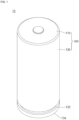
- FIG. 1 is a perspective view of a secondary battery according to one or more embodiments of the present disclosure.
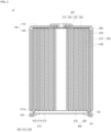
- FIG. 2 is a cross-sectional view of the cylindrical secondary battery according to FIG. 1 .
- the secondary battery 10 which may be a cylindrical secondary battery, according to one or more embodiments of the present disclosure may include a can 100, which may be cylindrical, an electrode assembly 200 accommodated inside the can 100, a first electrode current collector plate 300, a second electrode current collector plate 400, a terminal portion 500 provided on one side of the can 100, and a cap assembly 600 provided on the other side of the can 100.
- the can 100 may include a upper surface portion 110, which may be circular, and a side portion 130, which may be cylindrical, extending downwardly from the upper surface portion 110. Because the lower side of the side portion 130 is open, the can 100 is shaped of a cylinder having an open lower end.
- a terminal hole may be formed through the center of the upper surface portion 110. A portion of the terminal portion 500 may be exposed to the outside of the secondary battery 10 through the terminal hole.
- the can 100 having the above-described structure may be made of steel, a steel alloy, aluminium, an aluminium alloy, or equivalents thereof, but the material is not limited thereto.
- the electrode assembly 200, the first electrode current collector plate 300, and the second electrode current collector plate 400 are accommodated within the can 100 together with an electrolyte.
- the electrode assembly 200 may be configured such that a first electrode plate 210, a second electrode plate 220, and a separator 230 interposed therebetween are wound into a cylindrical shape.
- the first electrode plate 210 may be a positive electrode plate
- the second electrode plate 220 may be a negative electrode plate. The opposite is also possible in one or more embodiments.
- a positive electrode active material layer may be formed by coating, etc. on at least one surface of an aluminium (Al) foil.
- the positive electrode active material layer may be a transition metal oxide (LiCoO 2 , LiNiO 2 , LiMn 2 O 4 , etc.).
- a first electrode uncoated portion, at which the positive electrode active material layer is not formed, may be provided on the first electrode plate 210.
- a plurality of first electrode substrate tabs may be formed by cutting the first electrode uncoated portion into a corresponding shape by notching, etc. In one or more embodiments, the first electrode substrate tabs may be located toward the upper surface portion 110 of the can 100.
- the first electrode substrate tabs may be electrically connected to the first electrode current collector plate 300.
- the first electrode substrate tabs may be bent in one direction, and then may be coupled to the first electrode current collector plate 300 by welding, which will later be described in detail.
- a negative electrode active material layer may be formed by coating at least one surface of a copper (Cu) or nickel (Ni) foil.
- the negative electrode active material layer may be graphite, carbon, etc.
- a second electrode uncoated portion, at which the negative electrode active material layer is not formed, may be provided in the second electrode plate 220.
- a plurality of second electrode substrate tabs may be formed by cutting the second electrode uncoated portion into a corresponding shape by notching, etc.
- the second electrode substrate tabs may be located toward the lower side of the can 100.
- the second electrode substrate tabs may protrude downwardly from the separator 230, and may be electrically connected to the second electrode current collector plate 400. Some portions of the second electrode substrate tabs may be electrically connected to the beading part 132 of the can 100.
- the second electrode substrate tabs may be bent in one direction, and then may be coupled to the second electrode current collector plate 400 by welding.
- the separator 230 may be polyethylene (PE) or polypropylene (PP), but is not limited thereto.
- the separator 230 may reduce or prevent the likelihood of an electrical short between the first electrode plate 210 and the second electrode plate 220, and may only allow movement of lithium ions.
- the separator 230 may have a length that is sufficient to be in contact with the second electrode current collector plate 400 based on the longitudinal direction of the electrode assembly 200, which will later be described in detail.
- the electrode assembly 200 having the above-described structure is electrically connected to the first electrode current collector plate 300 and the second electrode current collector plate 400, and is electrically connected to the terminal portion 500 and the can 100, respectively.
- the first electrode current collector plate 300 has a circular plate shape, and may be made of the same material as the first electrode plate 210.
- the first electrode current collector plate 300 may be made of aluminium or an aluminium alloy.
- the diameter of the first electrode current collector plate 300 may be less than the diameter of the can 100, which may reduce or prevent the likelihood of the first electrode current collector plate 300 being electrically connected to the can 100.
- the first electrode current collector plate 300 may be welded in a state in which the lower surface thereof is in contact with the first electrode substrate tab. In one or more embodiments, the first electrode current collector plate 300 and the first electrode plate 210 may be electrically connected.
- the upper surface of the first electrode current collector plate 300 may be welded to the rivet terminal 510 of the terminal portion 500, which will be described later.
- the first electrode current collector plate 300 and the rivet terminal 510 may be electrically connected.
- the first electrode plate 210 and the rivet terminal 510 may be electrically connected by the first electrode current collector plate 300, and the first electrode current collector plate 300 may become a path for current flow between the first electrode plate 210 and the rivet terminal 510.
- the second electrode current collector plate 400 may include a plate surface portion 410 having a circular plate shape, and a contact portion 420 extending from the plate surface portion 410.
- the contact portion 420 is an edge area of the second electrode current collector plate 400.
- the upper surface of the plate surface portion 410 may be welded in a state of being in contact with the second electrode substrate tab.
- the second electrode current collector plate 400 and the second electrode plate 220 may be electrically connected.
- the second electrode current collector plate 400 may be made of the same material as the second electrode plate 220.
- the second electrode current collector plate 400 may be made of copper.
- the contact portion 420 may extend downwardly from the edge of the plate surface portion 410.
- the contact portion 420 may be in close contact with the inner surface of the beading part 132.
- the contact portion 420 may have a curve corresponding to the curve of the beading part 132.
- the contact portion 420 may be welded to, and electrically connected to, the beading part 132.
- the second electrode current collector plate 400 is not electrically connected to the cap assembly 600.
- the terminal portion 500 may include a rivet terminal 510 and at least one insulator 520, 530, and 540 for insulating the rivet terminal 510.
- the rivet terminal 510 is inserted into a terminal hole formed in the upper surface portion 110 of the can 100.
- the rivet terminal 510 is electrically connected to the first electrode plate 210 through the first electrode current collector plate 300.
- the rivet terminal 510 is a terminal coupled to the upper surface portion 110 of the can 100 by a riveting method.
- the rivet terminal 510 may be inserted into the terminal hole from the outside of the can 100 toward the inside. In one or more embodiments, one end of the rivet terminal 510 is located outside the can 100, and the other end is located inside the can 100.
- the rivet terminal 510 When the rivet terminal 510 is coupled, at least one of the first to third insulators 520 to 540 are inserted between the rivet terminal 510 and the upper surface portion 110 of the can 100 to insulate the can 100 and the rivet terminal 510 from each other. In a state in which the rivet terminal 510 is inserted into the terminal hole, the inner end of the rivet terminal 510 is compressed and deformed by processing, such as by pressing or spinning. In one or more embodiments, the rivet terminal 510 may be in close contact with the upper surface portion 110 of the can 100.
- the insulator may include a first insulator 520, a second insulator 530, and a third insulator 540.
- the first insulator 520, the second insulator 530, and the third insulator 540 may be used without limitation in type as long as they are made of an insulating material.
- the first insulator 520 is located between the outer end of the rivet terminal 510 and the upper surface portion 110.
- the first insulator 520 may have a hollow circular plate shape.
- the diameter of the first insulator 520 may be larger than the diameter of the outer end of the rivet terminal 510.
- the second insulator 530 may be shaped to surround the terminal hole formed in the upper surface portion 110. In one or more embodiments, about the terminal hole, the second insulator 530 may be shaped to surround the outer and inner surfaces of the upper surface portion 110 and the cross section where the terminal hole is formed.
- the third insulator 540 is shaped of a hollow circular plate, and is located between the inner surface of the upper surface portion 110 and the inner end of the rivet terminal 510, which will later be described.
- One end of the second insulator 530 may be in close contact with the inside of the hollow side of the first insulator 520.
- the other end of the second insulator 530 may be in close contact with the inside of the hollow side of the third insulator 540.
- the first to third insulators may be formed integrally.
- the cap assembly 600 is provided on the opposite side of the upper surface portion 110 where the terminal portion 500 having the above-described structure is provided.
- the cap assembly 600 may include a cap plate 610 for sealing the can 100, and a gasket 620 for insulating the can 100 and the cap plate 610 from each other.
- the cap plate 610 may include a planar portion 612 having a circular plate shape, an inclined surface 614 connected to the planar portion 612, and an extension surface 616 connected to the inclined surface 614.
- the planar portion 612 may be located approximately parallel to the second electrode current collector plate 400.
- the inclined surface 614 may slantingly extend downwardly from the edge of the planar portion 612.
- the extension surface 616 extends from the edge of the inclined surface 614, and may be parallel to the planar portion 612.
- the extension surface 616 may be surrounded by the gasket 620, and may be located between the beading part 132 and the crimping part 134.
- a notch 612a may be formed on the planar portion 612.
- the notch 612a may be broken if the pressure inside the secondary battery 10 exceeds a corresponding pressure.
- the gas inside the secondary battery 10 may be discharged if the notch 612a is broken.
- the notch 612a may function as a vent.
- the contact portion 420 of the second electrode current collector plate 400, and the extension surface 616 of the cap plate 610 are not brought into contact with the gasket 620.
- the gasket 620 may insulate the cap plate 610 and the can 100 from each other, and may insulate the cap plate 610 and the second electrode current collector plate 400 from each other.
- the rivet terminal 510 may have a positive polarity, and the can 100 may have a negative polarity.
- both the rivet terminal 510 of a positive polarity, and the upper surface portion 110 of a negative polarity, may be provided on the upper side of the can 100.
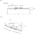
- FIG. 3 is a partial cross-sectional view showing a terminal structure according to FIG. 2 .
- FIG. 4 is a partial perspective view showing the terminal structure according to FIG. 2 .
- FIG. 5 is a perspective view showing an insulator according to FIG. 4 .
- FIG. 3 shows the terminal structure in a state in which the rivet terminal 510 faces the upper side of the secondary battery 10.
- FIG. 4 shows the terminal structure in a state in which the rivet terminal 510 faces the lower side of the secondary battery 10.
- FIG. 5 shows the shape of the third insulator 540 based on the same direction as FIG. 4 .
- the third insulator 540 has an approximately circular plate shape, and has a thickness (e.g., a predetermined thickness).
- the third insulator 540 may include a terminal contact portion 541 that is in contact with the rivet terminal 510, a current collector plate contact portion 543 that is in contact with the first electrode current collector plate 300, and an upper contact portion 545 that is in contact with the upper surface portion 110.
- the terminal contact portion 541 and the current collector plate contact portion 543 are connected to a first inclined portion 542.
- the current collector plate contact portion 543 and the upper contact portion 545 are connected to a second inclined portion 544.
- the terminal contact portion 541, the current collector plate contact portion 543, and the upper contact portion 545 have a step, or level difference, with respect to each other.
- the terminal contact portion 541, the first inclined portion 542, the current collector plate contact portion 543, the second inclined portion 544, and the upper contact portion 545 are all integrally formed.
- a plurality of grooves 546 are formed on the current collector plate contact portion 543 (see FIGS. 4 and 5 ).
- the terminal contact portion 541 is a partial area in the center of the third insulator 540 that has a circular plate shape.
- the terminal contact portion 541 is a circular area having a diameter that is larger than the inner end diameter of the rivet terminal 510.
- a terminal hole into which the rivet terminal 510 is inserted is formed in the center of the terminal contact portion 541.
- the terminal contact portion 541 is in close contact with the inner surface of the upper surface portion 110 if viewed with reference to FIG. 3 .
- the rivet terminal 510 is coupled in a state in which the terminal contact portion 541 is in close contact with the upper surface portion 110.
- the inner end of the rivet terminal 510 is deformed so that the terminal contact portion 541 can be brought into closer contact with the upper surface portion 110.
- the first inclined portion 542 is connected to the terminal contact portion 541.
- the first inclined portion 542 is located outside the terminal contact portion 541.
- the first inclined portion 542 slantingly extends downwardly from the edge of the terminal contact portion 541 toward the first electrode current collector plate 300.
- the first inclined portion 542 slantingly extends upwardly from the edge of the terminal contact portion 541.
- the current collector plate contact portion 543 is connected to the edge of the first inclined portion 542.
- the current collector plate contact portion 543 is a portion that occupies most of the area of the third insulator 540.
- the current collector plate contact portion 543 has a circular plate shape, and a terminal contact portion 541 is formed at the center thereof.
- the current collector plate contact portion 543 is located on the lower side at a corresponding distance from the upper surface portion 110.
- the current collector plate contact portion 543 is located on the upper side at a corresponding distance from the upper surface portion 110.
- the current collector plate contact portion 543 has a step from the terminal contact portion 541.
- the current collector plate contact portion 543 may be parallel to the terminal contact portion 541 and the upper surface portion 110.
- the grooves 546 having a substantially fan-shaped shape may be formed on the current collector plate contact portion 543.
- the grooves 546 may be formed concavely from the surface in the direction of the first electrode current collector plate 300.
- the grooves 546 are provided for reducing the weight of the third insulator 540 and may be omitted.
- the second inclined portion 544 is connected to the edge of the current collector plate contact portion 543.
- the second inclined portion 544 is located outside the current collector plate contact portion 543.
- the second inclined portion 544 slantingly extends upwardly from the edge of the current collector plate contact portion 543 toward the upper surface portion 110.
- the second inclined portion 544 extends at a downward angle from the edge of the current collector plate contact portion 543.
- the upper contact portion 545 is connected to the edge of the second inclined portion 544.
- the upper contact portion 545 is an area corresponding to the outer edge of the third insulator 540 if viewed as a whole. On the basis of FIG. 3 , the upper contact portion 545 is in contact with the inner surface of the upper surface portion 110. In one or more embodiments, the upper surface of the upper contact portion 545 may be located on the same line as the upper surface of the terminal contact portion 541. In one or more embodiments, this may mean that, if the third insulator is viewed alone, the upper surface of the upper contact portion 545 is located on the same line as the upper surface of the terminal contact portion 541.
- this may mean that the upper surface of the upper contact portion 545 is located on the same line as the upper surface of the terminal contact portion 541 if the third insulator is coupled to the rivet terminal.
- the upper contact portion 545 has a smaller width than the terminal contact portion 541 or the current collector plate contact portion 543. As an example, if the radial width of the current collector plate contact portion 543 is 100 (e.g., 100 arbitrary units), the radial width of the upper contact portion 545 may be 10 (e.g., 10 arbitrary units).
- the edge of the third insulator 540 may be formed only with the second inclined portion 544 without the upper contact portion 545.
- first and second inclined portions 542 and 544 are configurations for connecting the terminal contact portion 541, the current collector plate contact portion 543, and the upper contact portion 545 to one another while having a step with respect to one another.
- the current collector plate contact portion 543 and the upper contact portion 545 may also serve to support the first electrode current collector plate 300 during the manufacturing process.
- a step (H) between the terminal contact portion 541 and the current collector plate contact portion 543 is a height between the lower surface of the terminal contact portion 541 and the lower surface of the current collector plate contact portion 543, on the basis of FIG. 3 .
- the step between the terminal contact portion 541 and the current collector plate contact portion 543 is provided to secure an installation space for the rivet terminal 510.
- the step (H) between the terminal contact portion 541 and the current collector plate contact portion 543 is effectively provided.
- the current collector plate contact portion 543 presses the first electrode current collector plate 300 toward the electrode assembly 200. Then, the electrode assembly 200 may be pressed, resulting in deformation.
- the step between the terminal contact portion 541 and the current collector plate contact portion 543 may be set to be equal to or less than the protrusion height of the rivet terminal 510.
- the protrusion height of the rivet terminal 510 means a thickness ranging from the lower surface of the terminal contact portion 541 to the lower end (the lowermost part, regardless of the location) of the rivet terminal 510 on the basis of FIG. 3 (i.e., the thickness of the lower inner part of the rivet terminal). Even if the step (H) between the terminal contact portion 541 and the current collector plate contact portion 543 is less than the protrusion height of the rivet terminal 510, the step (H) may suitably be not more than 0.5 mm. If the step (H) is too large, the likelihood of the rivet terminal 510 contacting the first electrode current collector plate 300 may be reduced or prevented.
- the above-described terminal structure may include a structure to reduce or prevent rotation of the rivet terminal.
- FIG. 6 is a partial cross-sectional view showing a terminal structure according to one or more other embodiments of the present disclosure.
- a rivet terminal 510' may include a protrusion 510a at the lower portion that contacts the upper surface of the second insulator 530.
- the protrusion 510a may protrude in a circular shape.
- a plurality of protrusions having, for example, straight, hemispherical, oval, or streamlined shapes, may be arranged at regular intervals.
- a second insulator 530' may include an accommodation groove 530a shaped to correspond to the above-described protrusion 510a.
- the protrusion 510a and the accommodation groove 530a may be engaged with each other to reduce or prevent rotation of the rivet terminal 510' along the plate surface direction of the upper surface portion 110 in a state in which the rivet terminal 510' is coupled to the upper surface portion 110 of the can 100.
- the above-described protrusion 510a may be formed on the second insulator 530', and the accommodation groove 530a may be formed on the rivet terminal 510'.
- the size of the electrode assembly can be increased and the capacity of the secondary battery can be increased.
- shape deformation of the electrode assembly can be reduced or prevented during the manufacturing process.
- the size of the electrode assembly can be increased, and the capacity of the secondary battery can be increased.
Landscapes
- Chemical & Material Sciences (AREA)
- Chemical Kinetics & Catalysis (AREA)
- Electrochemistry (AREA)
- General Chemical & Material Sciences (AREA)
- Engineering & Computer Science (AREA)
- Manufacturing & Machinery (AREA)
- Connection Of Batteries Or Terminals (AREA)
Applications Claiming Priority (1)
| Application Number | Priority Date | Filing Date | Title |
|---|---|---|---|
| KR1020230074062A KR102853427B1 (ko) | 2023-06-09 | 2023-06-09 | 이차전지 |
Publications (2)
| Publication Number | Publication Date |
|---|---|
| EP4475289A2 true EP4475289A2 (de) | 2024-12-11 |
| EP4475289A3 EP4475289A3 (de) | 2025-04-02 |
Family
ID=91334996
Family Applications (1)
| Application Number | Title | Priority Date | Filing Date |
|---|---|---|---|
| EP24179132.6A Pending EP4475289A3 (de) | 2023-06-09 | 2024-05-30 | Sekundärbatterie |
Country Status (4)
| Country | Link |
|---|---|
| US (2) | US20240413503A1 (de) |
| EP (1) | EP4475289A3 (de) |
| KR (1) | KR102853427B1 (de) |
| CN (1) | CN119108772A (de) |
Family Cites Families (23)
| Publication number | Priority date | Publication date | Assignee | Title |
|---|---|---|---|---|
| CN201438490U (zh) * | 2009-04-30 | 2010-04-14 | 天津市捷威动力工业有限公司 | 一种锂离子动力电池 |
| KR101116492B1 (ko) * | 2010-02-12 | 2012-02-27 | 에스비리모티브 주식회사 | 이차 전지 |
| KR101243458B1 (ko) * | 2011-04-07 | 2013-03-13 | 로베르트 보쉬 게엠베하 | 절연 커버 부재를 구비한 이차 전지 |
| CN107658395B (zh) * | 2017-09-15 | 2021-02-05 | 惠州亿纬锂能股份有限公司 | 一种锂离子电池 |
| KR102487217B1 (ko) * | 2018-02-01 | 2023-01-11 | 주식회사 엘지에너지솔루션 | 리벳을 포함하는 캡 어셈블리 및 이를 포함하는 비딩부/클림핑부가 생략된 원통형 전지 |
| CN108565511A (zh) * | 2018-04-18 | 2018-09-21 | 浙江谷神能源科技股份有限公司 | 一种带双重安全保护的圆柱锂离子电池 |
| CN118102037A (zh) * | 2018-05-07 | 2024-05-28 | 苹果公司 | 用于查看实况视频馈送和录制视频的用户界面 |
| KR20220105118A (ko) * | 2021-01-19 | 2022-07-26 | 주식회사 엘지에너지솔루션 | 원통형 배터리 셀, 그리고 이를 포함하는 배터리 팩 및 자동차 |
| CA3202317A1 (en) * | 2021-01-19 | 2022-07-28 | Lg Energy Solution, Ltd. | Battery and current collector applied thereto, and battery pack and vehicle including the same |
| CN215578778U (zh) * | 2021-05-21 | 2022-01-18 | 湖北亿纬动力有限公司 | 一种新型结构的圆柱型电池 |
| DE102021115798A1 (de) * | 2021-06-18 | 2022-12-22 | Bayerische Motoren Werke Aktiengesellschaft | Batteriezelle und Verfahren zur Herstellung einer Batteriezelle |
| KR102525388B1 (ko) * | 2021-06-30 | 2023-04-26 | 삼성에스디아이 주식회사 | 이차전지 |
| EP4258462A4 (de) * | 2021-09-30 | 2024-10-09 | LG Energy Solution, Ltd. | Zylindrische batteriezelle, batteriepack und fahrzeug damit sowie verfahren zur herstellung einer zylindrischen batteriezelle |
| JP2024534588A (ja) * | 2021-10-14 | 2024-09-20 | エルジー エナジー ソリューション リミテッド | リチウム二次電池 |
| CN116670897B (zh) * | 2021-10-20 | 2025-07-29 | 宁德时代新能源科技股份有限公司 | 电池单体及其制造方法和制造系统、电池以及用电装置 |
| KR102712872B1 (ko) * | 2021-10-28 | 2024-10-04 | (주) 에스피시스템스 | 캡조립체의 측면 배치 구조 |
| US12494535B2 (en) * | 2022-03-15 | 2025-12-09 | Microvast Power Systems Co., Ltd. | Battery assembly and preparation method, battery and electric vehicle |
| CN218039734U (zh) * | 2022-06-09 | 2022-12-13 | 湖北亿纬动力有限公司 | 一种第一端子端子内部连接结构及电池 |
| CN217788587U (zh) * | 2022-06-28 | 2022-11-11 | 湖北亿纬动力有限公司 | 一种盖帽组件、电池、电池模组、电池包及车辆 |
| KR102554328B1 (ko) * | 2022-10-05 | 2023-07-11 | 삼성에스디아이 주식회사 | 원통형 이차전지 |
| KR102570308B1 (ko) * | 2022-10-27 | 2023-08-24 | 삼성에스디아이 주식회사 | 원통형 이차 전지 |
| CN218827495U (zh) * | 2022-12-14 | 2023-04-07 | 中创新航科技股份有限公司 | 电池包 |
| KR20240156729A (ko) * | 2023-04-24 | 2024-10-31 | 삼성에스디아이 주식회사 | 원통형 이차전지 |
-
2023
- 2023-06-09 KR KR1020230074062A patent/KR102853427B1/ko active Active
-
2024
- 2024-04-01 US US18/623,836 patent/US20240413503A1/en active Pending
- 2024-05-30 EP EP24179132.6A patent/EP4475289A3/de active Pending
- 2024-06-07 CN CN202410735451.3A patent/CN119108772A/zh active Pending
-
2025
- 2025-11-20 US US19/395,943 patent/US20260081324A1/en active Pending
Also Published As
| Publication number | Publication date |
|---|---|
| KR102853427B1 (ko) | 2025-09-02 |
| US20240413503A1 (en) | 2024-12-12 |
| US20260081324A1 (en) | 2026-03-19 |
| EP4475289A3 (de) | 2025-04-02 |
| CN119108772A (zh) | 2024-12-10 |
| KR20240174615A (ko) | 2024-12-17 |
Similar Documents
| Publication | Publication Date | Title |
|---|---|---|
| EP4468506A1 (de) | Sekundärbatterie | |
| EP4160794A1 (de) | Sekundärbatterie | |
| EP4123794A1 (de) | Sekundärbatterie | |
| EP4216363A1 (de) | Zylindrische sekundärbatterie | |
| EP4191782A1 (de) | Zylindrische sekundärbatterie | |
| JP5203729B2 (ja) | 二次電池及び電池モジュール | |
| EP4216345A1 (de) | Sekundärbatterie | |
| EP4376177A1 (de) | Sekundärbatterie | |
| EP4597656A1 (de) | Zylindrische sekundärbatterie | |
| EP4629432A1 (de) | Sekundärbatterie | |
| EP4354605A1 (de) | Zylindrische sekundärbatterie | |
| US12562403B2 (en) | Secondary battery | |
| EP4362153A1 (de) | Sekundärbatterie | |
| EP4475289A2 (de) | Sekundärbatterie | |
| EP4496066A1 (de) | Zylindrische sekundärbatterie | |
| US20240413497A1 (en) | Cylindrical secondary battery | |
| US20250105407A1 (en) | Secondary battery | |
| EP4451435A2 (de) | Sekundärbatterie | |
| EP4657617A2 (de) | Sekundärbatterie | |
| KR102950673B1 (ko) | 원통형 이차전지 | |
| EP4708470A2 (de) | Einspritzlochabdeckung sowie batteriezelle und batteriemodul damit | |
| EP4571957A1 (de) | Zylindrische sekundärbatterie | |
| EP4525184A1 (de) | Sekundärbatterie | |
| US20260112681A1 (en) | Secondary battery and method for manufacturing the same | |
| EP4586347A1 (de) | Batteriezelle und herstellungsverfahren dafür |
Legal Events
| Date | Code | Title | Description |
|---|---|---|---|
| PUAI | Public reference made under article 153(3) epc to a published international application that has entered the european phase |
Free format text: ORIGINAL CODE: 0009012 |
|
| STAA | Information on the status of an ep patent application or granted ep patent |
Free format text: STATUS: REQUEST FOR EXAMINATION WAS MADE |
|
| 17P | Request for examination filed |
Effective date: 20240530 |
|
| AK | Designated contracting states |
Kind code of ref document: A2 Designated state(s): AL AT BE BG CH CY CZ DE DK EE ES FI FR GB GR HR HU IE IS IT LI LT LU LV MC ME MK MT NL NO PL PT RO RS SE SI SK SM TR |
|
| PUAL | Search report despatched |
Free format text: ORIGINAL CODE: 0009013 |
|
| AK | Designated contracting states |
Kind code of ref document: A3 Designated state(s): AL AT BE BG CH CY CZ DE DK EE ES FI FR GB GR HR HU IE IS IT LI LT LU LV MC ME MK MT NL NO PL PT RO RS SE SI SK SM TR |
|
| RIC1 | Information provided on ipc code assigned before grant |
Ipc: H01M 50/593 20210101ALI20250226BHEP Ipc: H01M 50/152 20210101ALI20250226BHEP Ipc: H01M 10/04 20060101ALI20250226BHEP Ipc: H01M 10/0525 20100101ALI20250226BHEP Ipc: H01M 50/559 20210101ALI20250226BHEP Ipc: H01M 50/548 20210101ALI20250226BHEP Ipc: H01M 50/188 20210101ALI20250226BHEP Ipc: H01M 50/184 20210101ALI20250226BHEP Ipc: H01M 50/179 20210101ALI20250226BHEP Ipc: H01M 50/107 20210101AFI20250226BHEP |