EP4475111A1 - Anzeigevorrichtung - Google Patents
Anzeigevorrichtung Download PDFInfo
- Publication number
- EP4475111A1 EP4475111A1 EP23831675.6A EP23831675A EP4475111A1 EP 4475111 A1 EP4475111 A1 EP 4475111A1 EP 23831675 A EP23831675 A EP 23831675A EP 4475111 A1 EP4475111 A1 EP 4475111A1
- Authority
- EP
- European Patent Office
- Prior art keywords
- gear
- frame
- display panel
- display apparatus
- display
- Prior art date
- Legal status (The legal status is an assumption and is not a legal conclusion. Google has not performed a legal analysis and makes no representation as to the accuracy of the status listed.)
- Pending
Links
Images


Classifications
-
- F—MECHANICAL ENGINEERING; LIGHTING; HEATING; WEAPONS; BLASTING
- F16—ENGINEERING ELEMENTS AND UNITS; GENERAL MEASURES FOR PRODUCING AND MAINTAINING EFFECTIVE FUNCTIONING OF MACHINES OR INSTALLATIONS; THERMAL INSULATION IN GENERAL
- F16M—FRAMES, CASINGS OR BEDS OF ENGINES, MACHINES OR APPARATUS, NOT SPECIFIC TO ENGINES, MACHINES OR APPARATUS PROVIDED FOR ELSEWHERE; STANDS; SUPPORTS
- F16M11/00—Stands or trestles as supports for apparatus or articles placed thereon ; Stands for scientific apparatus such as gravitational force meters
- F16M11/02—Heads
- F16M11/04—Means for attachment of apparatus; Means allowing adjustment of the apparatus relatively to the stand
- F16M11/043—Allowing translations
- F16M11/045—Allowing translations adapted to left-right translation movement
-
- H—ELECTRICITY
- H05—ELECTRIC TECHNIQUES NOT OTHERWISE PROVIDED FOR
- H05K—PRINTED CIRCUITS; CASINGS OR CONSTRUCTIONAL DETAILS OF ELECTRIC APPARATUS; MANUFACTURE OF ASSEMBLAGES OF ELECTRICAL COMPONENTS
- H05K5/00—Casings, cabinets or drawers for electric apparatus
- H05K5/02—Details
- H05K5/0217—Mechanical details of casings
-
- F—MECHANICAL ENGINEERING; LIGHTING; HEATING; WEAPONS; BLASTING
- F16—ENGINEERING ELEMENTS AND UNITS; GENERAL MEASURES FOR PRODUCING AND MAINTAINING EFFECTIVE FUNCTIONING OF MACHINES OR INSTALLATIONS; THERMAL INSULATION IN GENERAL
- F16B—DEVICES FOR FASTENING OR SECURING CONSTRUCTIONAL ELEMENTS OR MACHINE PARTS TOGETHER, e.g. NAILS, BOLTS, CIRCLIPS, CLAMPS, CLIPS OR WEDGES; JOINTS OR JOINTING
- F16B35/00—Screw-bolts; Stay-bolts; Screw-threaded studs; Screws; Set screws
-
- F—MECHANICAL ENGINEERING; LIGHTING; HEATING; WEAPONS; BLASTING
- F16—ENGINEERING ELEMENTS AND UNITS; GENERAL MEASURES FOR PRODUCING AND MAINTAINING EFFECTIVE FUNCTIONING OF MACHINES OR INSTALLATIONS; THERMAL INSULATION IN GENERAL
- F16H—GEARING
- F16H1/00—Toothed gearings for conveying rotary motion
- F16H1/02—Toothed gearings for conveying rotary motion without gears having orbital motion
- F16H1/20—Toothed gearings for conveying rotary motion without gears having orbital motion involving more than two intermeshing members
-
- F—MECHANICAL ENGINEERING; LIGHTING; HEATING; WEAPONS; BLASTING
- F16—ENGINEERING ELEMENTS AND UNITS; GENERAL MEASURES FOR PRODUCING AND MAINTAINING EFFECTIVE FUNCTIONING OF MACHINES OR INSTALLATIONS; THERMAL INSULATION IN GENERAL
- F16M—FRAMES, CASINGS OR BEDS OF ENGINES, MACHINES OR APPARATUS, NOT SPECIFIC TO ENGINES, MACHINES OR APPARATUS PROVIDED FOR ELSEWHERE; STANDS; SUPPORTS
- F16M11/00—Stands or trestles as supports for apparatus or articles placed thereon ; Stands for scientific apparatus such as gravitational force meters
- F16M11/02—Heads
- F16M11/04—Means for attachment of apparatus; Means allowing adjustment of the apparatus relatively to the stand
- F16M11/043—Allowing translations
- F16M11/048—Allowing translations adapted to forward-backward translation movement
-
- F—MECHANICAL ENGINEERING; LIGHTING; HEATING; WEAPONS; BLASTING
- F16—ENGINEERING ELEMENTS AND UNITS; GENERAL MEASURES FOR PRODUCING AND MAINTAINING EFFECTIVE FUNCTIONING OF MACHINES OR INSTALLATIONS; THERMAL INSULATION IN GENERAL
- F16M—FRAMES, CASINGS OR BEDS OF ENGINES, MACHINES OR APPARATUS, NOT SPECIFIC TO ENGINES, MACHINES OR APPARATUS PROVIDED FOR ELSEWHERE; STANDS; SUPPORTS
- F16M11/00—Stands or trestles as supports for apparatus or articles placed thereon ; Stands for scientific apparatus such as gravitational force meters
- F16M11/02—Heads
- F16M11/18—Heads with mechanism for moving the apparatus relatively to the stand
-
- F—MECHANICAL ENGINEERING; LIGHTING; HEATING; WEAPONS; BLASTING
- F16—ENGINEERING ELEMENTS AND UNITS; GENERAL MEASURES FOR PRODUCING AND MAINTAINING EFFECTIVE FUNCTIONING OF MACHINES OR INSTALLATIONS; THERMAL INSULATION IN GENERAL
- F16M—FRAMES, CASINGS OR BEDS OF ENGINES, MACHINES OR APPARATUS, NOT SPECIFIC TO ENGINES, MACHINES OR APPARATUS PROVIDED FOR ELSEWHERE; STANDS; SUPPORTS
- F16M11/00—Stands or trestles as supports for apparatus or articles placed thereon ; Stands for scientific apparatus such as gravitational force meters
- F16M11/20—Undercarriages with or without wheels
- F16M11/2085—Undercarriages with or without wheels comprising means allowing sideward adjustment, i.e. left-right translation of the head relatively to the undercarriage
-
- F—MECHANICAL ENGINEERING; LIGHTING; HEATING; WEAPONS; BLASTING
- F16—ENGINEERING ELEMENTS AND UNITS; GENERAL MEASURES FOR PRODUCING AND MAINTAINING EFFECTIVE FUNCTIONING OF MACHINES OR INSTALLATIONS; THERMAL INSULATION IN GENERAL
- F16M—FRAMES, CASINGS OR BEDS OF ENGINES, MACHINES OR APPARATUS, NOT SPECIFIC TO ENGINES, MACHINES OR APPARATUS PROVIDED FOR ELSEWHERE; STANDS; SUPPORTS
- F16M11/00—Stands or trestles as supports for apparatus or articles placed thereon ; Stands for scientific apparatus such as gravitational force meters
- F16M11/20—Undercarriages with or without wheels
- F16M11/2092—Undercarriages with or without wheels comprising means allowing depth adjustment, i.e. forward-backward translation of the head relatively to the undercarriage
-
- G—PHYSICS
- G09—EDUCATION; CRYPTOGRAPHY; DISPLAY; ADVERTISING; SEALS
- G09F—DISPLAYING; ADVERTISING; SIGNS; LABELS OR NAME-PLATES; SEALS
- G09F9/00—Indicating arrangements for variable information in which the information is built-up on a support by selection or combination of individual elements
- G09F9/30—Indicating arrangements for variable information in which the information is built-up on a support by selection or combination of individual elements in which the desired character or characters are formed by combining individual elements
- G09F9/302—Indicating arrangements for variable information in which the information is built-up on a support by selection or combination of individual elements in which the desired character or characters are formed by combining individual elements characterised by the form or geometrical disposition of the individual elements
- G09F9/3026—Video wall, i.e. stackable semiconductor matrix display modules
-
- H—ELECTRICITY
- H05—ELECTRIC TECHNIQUES NOT OTHERWISE PROVIDED FOR
- H05K—PRINTED CIRCUITS; CASINGS OR CONSTRUCTIONAL DETAILS OF ELECTRIC APPARATUS; MANUFACTURE OF ASSEMBLAGES OF ELECTRICAL COMPONENTS
- H05K5/00—Casings, cabinets or drawers for electric apparatus
- H05K5/30—Side-by-side or stacked arrangements
Definitions
- the disclosure relates to a display apparatus and, more particularly to, a display apparatus of which a position of panels may be adjusted.
- a modular display apparatus has a large-sized screen by consecutively tiling a plurality of panels.
- the modular display apparatus has a problem in that image quality degradation and a sense of difference may occur due to a gap and a step between modules (i.e., panels).
- a display apparatus having multiple display panels and capable of precisely adjusting positions of the multiple display panels and a method thereof.
- a display apparatus includes: a frame; a plurality of display panels detachably mounted on the frame and including a first display panel and a second display panel; and a position adjusting unit provided in the frame and provided between the first display panel and the second display panel.
- the position adjusting unit includes: a first gear and a second gear configured to be rotatably connected to the frame, a third gear configured to mount the first display panel on a surface of the third gear by being coupled to the frame and by being interlocked with the first gear, and a fourth gear configured to mount the second display panel on a surface of the fourth gear by being coupled to the frame and by being interlocked with the second gear.
- the third gear may be coupled to the frame via a first screw and the fourth gear may be coupled to the frame via a second screw.
- Each of the first gear and the second gear may include a guide groove configured to insert a tool for rotating the first gear or the second gear.
- the third gear may be provided further to a left side of the display apparatus than the fourth gear.
- a height of the third gear may be the same as a height of the fourth gear.
- the frame may include: a base; and a rib member protruding in a front side further than the base, wherein the rib member is configured to support the position adjusting unit and to have a hollow at which rear ends of the first gear, the second gear, the third gear, and the fourth gear are provided.
- the plurality of display panels may be provided slidable in left or right directions of the frame.
- the plurality of display panels may include a hook member at an upper side, and the frame comprises a guide to support the hook member upward to be slidable in a right direction and a left direction.
- a display apparatus includes: a frame; a first display panel configured to be detachably mounted on the frame; a first gear configured to be rotatably connected to the frame; and a third gear configured to be interlocked with the first gear and to be coupled to the frame.
- the third gear is configured to mount the first display panel on a surface of the third gear and to move the first display panel in the first direction, based on a rotational force applied to the third gear.
- the display apparatus may further include: a second display panel configured to be detachably mounted on the frame; a second gear configured to be rotatably connected to the frame; and a fourth gear configured to be interlocked with the second gear and to be coupled to the frame.
- the fourth gear is configured to mount the second display panel on a surface of the fourth gear and to move the second display panel in the second direction, based on a rotational force applied to the fourth gear.
- the term “has,” “may have,” “includes” or “may include” indicates existence of a corresponding feature (e.g., a numerical value, a function, an operation, or a constituent element such as a component), but does not exclude existence of an additional feature.
- components required for the description of each embodiment of the disclosure are described and thus, the embodiment is not necessarily limited thereto. Accordingly, some components may be changed or omitted and other components may be added. In addition, components may be disposed and arranged in different independent devices.
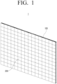
- FIG. 1 is a perspective view of a display apparatus according to an embodiment of the disclosure
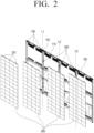
- FIG. 2 is an exploded perspective view of the display apparatus of FIG. 1
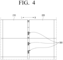
- FIG. 3 is a front view illustrating that the first and second display panels are spaced apart in left directions and right directions.
- a display apparatus 1 may include a plurality of display panels 200.
- the display apparatus 1 may display a video signal.
- the display apparatus 1 may be implemented as a television (TV), but is not limited thereto, and may be applicable to any device having a display function such as a video wall, a large format display (LFD), a digital signage, and a digital information display (DID), or the like.
- TV television
- LFD large format display
- DID digital information display
- the display apparatus 1 may be various types displays, such as a liquid crystal display (LCD), an organic light-emitting diode (OLED), a liquid crystal on silicon (LCoS), a digital light processing (DLP), a quantum dot (QD) display panel, a quantum dot light-emitting diodes (QLED), or the like.
- LCD liquid crystal display
- OLED organic light-emitting diode
- LCDoS liquid crystal on silicon
- DLP digital light processing
- QD quantum dot
- QLED quantum dot light-emitting diodes
- the display apparatus 1 may include a plurality of display panels (or a cabinet) 200.
- a plurality of display panels (or a cabinet) 200 For example, as shown in FIG. 1 , four display panels 200 may be coupled along left and right directions to implement one display apparatus 1.
- Each of the plurality of display panels 200 according to an embodiment of the disclosure may include a plurality of self-luminous elements, such as a light-emitting diode (LED) or a micro LED.
- LED light-emitting diode
- micro LED micro LED
- Each of the plurality of display panels 200 may be an LED cabinet including a plurality of LED elements.
- the LED element may be implemented as a red/green/blue (RGB) LED, which may include red LED, green LED, and blue LED.
- the LED element may additionally include a white LED, in addition to the RGB LED.
- the LED element may be a micro LED.
- the micro LED may be a LED at a size of about 5 to 100 micrometers and may be a micro-sized light-emitting element that emits light by itself without a color filter.
- the display apparatus 1 may include a frame 100, the plurality of display panels 200, and a position adjusting unit 300.
- the display apparatus 1 includes the frame 100 that supports the display panel 200.
- the display panel 200 may implement a screen of the display apparatus 1.
- the frame 100 may have an approximately rectangular shape, and may include a frame body covering the rear of the display panel 200 and a frame cover surrounding the edge portion of the frame body.
- the frame cover may form an outer appearance of an upper surface, an outer appearance of a lower surface, and an outer appearance of a side surface of the display apparatus 1.
- the display apparatus 1 may include a device board.
- the device board may include a switching mode power supply (SMPS) provided to supply power required for driving the display apparatus 1, at least one printed circuit board (PCB), and a signal processing board for processing data.
- SMPS switching mode power supply
- PCB printed circuit board
- the device board may be disposed on the frame 100, but is not limited thereto, and may be disposed on the display panel 200.
- the device board may be provided in the same number as the number of display panels 200.
- four device boards may supply power and image data to each of the four display panels 200.
- a sub-board and a cable for receiving data from each device board may be respectively arranged in the plurality of display panels 200.
- the display panel 200 may receive image data from the device board and display an image.
- the plurality of display panels 200 may be detachably mounted on a frame 100.
- the rear surface of the display panel 200 may be attached to or detached from the front surface of the frame 100 by a magnetic force.
- a plurality of first coupling members disposed on the front surface of the frame 100 and a plurality of second coupling members disposed on the rear surface (or the rear surface) of the display panel 200 may be detachably coupled to each other by attraction.
- the position adjusting unit 300 is provided in the frame 100 and may be disposed between the first display panel 210 and the second display panel 220 disposed adjacent to each other in the left and right directions among the plurality of display panels 200.
- the position adjusting unit 300 may move the first display panel 210 and the second display panel 220, and thus, arrange the panels in left and right directions or toward front or rear directions. Accordingly, steps (or gaps) between the front and rear sides of the first display panel 210 and the second display panel 220 may be adjusted.
- the first gear 310 may be disposed at a lower side of the second gear 320. In one embodiment, the first gear 310 may be disposed to be more left than the second gear 320. For example, the first gear 310 may be eccentrically disposed to the left side than the virtual vertical line, and the second gear 320 may be eccentrically disposed to the right side than the virtual vertical line.
- the third gear 330 may be disposed on the left side than the fourth gear 340.
- the third gear 330 may be disposed at a height corresponding to a height of the fourth gear 340. Accordingly, one point of the first display panel 210 in contact with the third gear 330 and one point of the second display panel 220 in contact with the fourth gear 340 may be located at the same height.
- the first gear 310 and the second gear 320 may include guide a first guide groove 311 and a second guide groove 321 into which a tool for rotating the first gear 310 and the second gear 320 may be inserted.
- the user may rotate the first gear 310 and the second gear 320 by inserting a tool into the first guide groove 311 of the first gear 310 and the second guide groove 321 of the second gear 320, instead of directly rotating the gear blades of the first gear 310 and the second gear 320. Accordingly, the user may easily rotate the first gear 310 and the second gear 320 with high force transmission efficiency.
- each of the first guide groove 311 of the first gear 310 and the second guide groove 321 of the second gear 320 may have a shape of a long groove in a vertical direction.
- the guide grooves 311, 321 may have a non-circular shape. Accordingly, a user may easily rotate the first gear 310 and the second gear 320 with high force transmission efficiency.
- the frame 100 may include a first hole H1 and a second hole H2 through which the first gear 310 and the second gear 320 pass, respectively.
- the frame 100 may also include a third hole H3 and a fourth hole H4 through which the third gear 330 and the fourth gear 340 pass, respectively. Screws engaged with the third gear 330 and the fourth gear 340 may be formed on inner circumferential surfaces of the third hole H3 and the fourth hole H4.
- the rib member 120 may be elongated along a plurality of vertical lines (L1, L2, L3).
- the rib member 120 may have a hollow 121 in which the rear ends of the first to fourth gears 310, 320, 330, 340 are arranged.
- the rib member 120 may be penetrated by the first gear 310, the second gear 320, the third gear 330, and the fourth gear 340.
- the second display panel 220 may be disposed to be stepped rearward by a step "S" as compared to the first display panel 210. Accordingly, the user may rotate the second gear 320 in one direction. Thereafter, the fourth gear 340 rotates by being engaged with the second gear 320, and is coupled to the frame 100 by a screw so that the fourth gear 340 may move forward at the same time. As shown in FIG. 7 , the second display panel 220 mounted on the front surface 341 of the fourth gear 340 may move forward to be arranged, thus the step ("S") with respect to the first display panel 210 is removed.
Landscapes
- Engineering & Computer Science (AREA)
- General Engineering & Computer Science (AREA)
- Mechanical Engineering (AREA)
- Microelectronics & Electronic Packaging (AREA)
- Multimedia (AREA)
- Physics & Mathematics (AREA)
- General Physics & Mathematics (AREA)
- Theoretical Computer Science (AREA)
- Devices For Indicating Variable Information By Combining Individual Elements (AREA)
Applications Claiming Priority (2)
| Application Number | Priority Date | Filing Date | Title |
|---|---|---|---|
| KR1020220080026A KR20240002620A (ko) | 2022-06-29 | 2022-06-29 | 디스플레이 장치 |
| PCT/KR2023/004376 WO2024005309A1 (ko) | 2022-06-29 | 2023-03-31 | 디스플레이 장치 |
Publications (2)
| Publication Number | Publication Date |
|---|---|
| EP4475111A1 true EP4475111A1 (de) | 2024-12-11 |
| EP4475111A4 EP4475111A4 (de) | 2025-05-28 |
Family
ID=89380870
Family Applications (1)
| Application Number | Title | Priority Date | Filing Date |
|---|---|---|---|
| EP23831675.6A Pending EP4475111A4 (de) | 2022-06-29 | 2023-03-31 | Anzeigevorrichtung |
Country Status (5)
| Country | Link |
|---|---|
| US (2) | US12446170B2 (de) |
| EP (1) | EP4475111A4 (de) |
| KR (1) | KR20240002620A (de) |
| CN (1) | CN119013716A (de) |
| WO (1) | WO2024005309A1 (de) |
Families Citing this family (1)
| Publication number | Priority date | Publication date | Assignee | Title |
|---|---|---|---|---|
| WO2025244158A1 (ko) | 2024-05-24 | 2025-11-27 | 엘지전자 주식회사 | 디스플레이 디바이스 |
Family Cites Families (12)
| Publication number | Priority date | Publication date | Assignee | Title |
|---|---|---|---|---|
| JP6378104B2 (ja) | 2015-01-30 | 2018-08-22 | 株式会社フォトクラフト社 | 映像表示装置、及び、それの組み立て調整方法 |
| KR102272059B1 (ko) | 2015-02-09 | 2021-07-05 | 삼성전자주식회사 | 디스플레이 모듈 및 이를 포함하는 디스플레이 장치 |
| KR101705511B1 (ko) * | 2015-10-08 | 2017-03-31 | 주식회사 에이블테크 | 디스플레이 장치 |
| JP6758492B2 (ja) * | 2017-05-22 | 2020-09-23 | 三菱電機株式会社 | 表示モジュール群、表示装置、及び表示装置の製造方法 |
| RU2716140C1 (ru) | 2018-02-06 | 2020-03-06 | Мицубиси Электрик Корпорейшн | Многодисплейная система и устройство отображения видеоинформации |
| KR102455299B1 (ko) | 2018-03-07 | 2022-10-17 | 엘지전자 주식회사 | 디스플레이 디바이스 |
| US11353732B2 (en) * | 2018-08-24 | 2022-06-07 | Samsung Electronics Co., Ltd. | Display apparatus |
| KR102489223B1 (ko) | 2018-09-28 | 2023-01-17 | 엘지디스플레이 주식회사 | 멀티디스플레이의 갭 조절장치 및 이를 갖는 멀티디스플레이 |
| CN210715418U (zh) * | 2019-09-02 | 2020-06-09 | 利亚德光电股份有限公司 | 显示屏的间隙调节工具和显示屏组件 |
| CN111425722A (zh) * | 2020-05-07 | 2020-07-17 | 深圳市亮彩科技有限公司 | Led四屏自动联动装置 |
| EP4207146A4 (de) * | 2020-08-28 | 2024-08-28 | LG Electronics Inc. | Anzeigegerät |
| CN113700996B (zh) * | 2021-08-24 | 2023-08-01 | 深圳市华星光电半导体显示技术有限公司 | 拼接屏间隙调节装置及调节方法 |
-
2022
- 2022-06-29 KR KR1020220080026A patent/KR20240002620A/ko active Pending
-
2023
- 2023-03-31 EP EP23831675.6A patent/EP4475111A4/de active Pending
- 2023-03-31 CN CN202380036492.7A patent/CN119013716A/zh active Pending
- 2023-03-31 WO PCT/KR2023/004376 patent/WO2024005309A1/ko not_active Ceased
- 2023-04-26 US US18/139,472 patent/US12446170B2/en active Active
-
2025
- 2025-09-24 US US19/338,553 patent/US20260020170A1/en active Pending
Also Published As
| Publication number | Publication date |
|---|---|
| WO2024005309A1 (ko) | 2024-01-04 |
| CN119013716A (zh) | 2024-11-22 |
| US20240008198A1 (en) | 2024-01-04 |
| US12446170B2 (en) | 2025-10-14 |
| EP4475111A4 (de) | 2025-05-28 |
| US20260020170A1 (en) | 2026-01-15 |
| KR20240002620A (ko) | 2024-01-05 |
Similar Documents
| Publication | Publication Date | Title |
|---|---|---|
| US11935440B2 (en) | Display apparatus and hinge assembly of display module | |
| US11674218B2 (en) | Lightweight unitary display | |
| CN111966309B (zh) | 显示装置以及具有该显示装置的显示系统 | |
| US20260020170A1 (en) | Display apparatus | |
| EP3799656B1 (de) | Anzeigevorrichtung | |
| EP1722267B1 (de) | Hintergrundbeleuchtungseinheit und damit ausgestattete Flüssigkristallanzeige | |
| KR102590119B1 (ko) | 디스플레이 장치 | |
| EP2487404A1 (de) | Lichtquellenmodul und elektronische vorrichtung damit | |
| KR102209285B1 (ko) | 높이조절식 엘이디 디스플레이장치 | |
| EP3276978B1 (de) | Tonsystem und anzeigevorrichtung damit | |
| KR20170118318A (ko) | 디스플레이장치 | |
| US20250071917A1 (en) | Connection bracket and display apparatus including the same | |
| US12288488B2 (en) | Display apparatus | |
| EP4668049A1 (de) | Verbindungsklammer und anzeigevorrichtung damit | |
| CN114974051A (zh) | Led显示屏的控制方法、led显示屏及电子设备 | |
| KR102847144B1 (ko) | 디스플레이 디바이스 | |
| KR102843566B1 (ko) | 디스플레이 디바이스 | |
| KR102452144B1 (ko) | 높낮이 조절구가 구비된 led전광판 | |
| US20250089188A1 (en) | Display apparatus | |
| US20250285563A1 (en) | Display apparatus | |
| US20250318064A1 (en) | Separation device and display device comprising same | |
| KR20250028138A (ko) | 연결 브래킷 및 이를 포함하는 디스플레이 장치 | |
| KR20250028913A (ko) | 연결 브래킷 및 이를 포함하는 디스플레이 장치 | |
| KR20230134897A (ko) | 엘이디 전광판 | |
| WO2013058295A1 (ja) | バックライト装置、表示装置、及びテレビ受信装置 |
Legal Events
| Date | Code | Title | Description |
|---|---|---|---|
| STAA | Information on the status of an ep patent application or granted ep patent |
Free format text: STATUS: THE INTERNATIONAL PUBLICATION HAS BEEN MADE |
|
| PUAI | Public reference made under article 153(3) epc to a published international application that has entered the european phase |
Free format text: ORIGINAL CODE: 0009012 |
|
| STAA | Information on the status of an ep patent application or granted ep patent |
Free format text: STATUS: REQUEST FOR EXAMINATION WAS MADE |
|
| 17P | Request for examination filed |
Effective date: 20240905 |
|
| AK | Designated contracting states |
Kind code of ref document: A1 Designated state(s): AL AT BE BG CH CY CZ DE DK EE ES FI FR GB GR HR HU IE IS IT LI LT LU LV MC ME MK MT NL NO PL PT RO RS SE SI SK SM TR |
|
| A4 | Supplementary search report drawn up and despatched |
Effective date: 20250429 |
|
| RIC1 | Information provided on ipc code assigned before grant |
Ipc: F16H 1/20 20060101ALI20250423BHEP Ipc: F16B 35/00 20060101ALI20250423BHEP Ipc: G09F 9/302 20060101AFI20250423BHEP |
|
| DAV | Request for validation of the european patent (deleted) | ||
| DAX | Request for extension of the european patent (deleted) |