EP4474742A2 - Drying apparatus and oven - Google Patents
Drying apparatus and oven Download PDFInfo
- Publication number
- EP4474742A2 EP4474742A2 EP24209300.3A EP24209300A EP4474742A2 EP 4474742 A2 EP4474742 A2 EP 4474742A2 EP 24209300 A EP24209300 A EP 24209300A EP 4474742 A2 EP4474742 A2 EP 4474742A2
- Authority
- EP
- European Patent Office
- Prior art keywords
- air
- outlet channel
- sub
- drying
- connecting portion
- Prior art date
- Legal status (The legal status is an assumption and is not a legal conclusion. Google has not performed a legal analysis and makes no representation as to the accuracy of the status listed.)
- Granted
Links
Images



Classifications
-
- F—MECHANICAL ENGINEERING; LIGHTING; HEATING; WEAPONS; BLASTING
- F26—DRYING
- F26B—DRYING SOLID MATERIALS OR OBJECTS BY REMOVING LIQUID THEREFROM
- F26B21/00—Arrangements for supplying or controlling air or other gases for drying solid materials or objects
- F26B21/30—Controlling, e.g. regulating, parameters of gas supply
- F26B21/37—Velocity of flow; Quantity of flow
-
- F—MECHANICAL ENGINEERING; LIGHTING; HEATING; WEAPONS; BLASTING
- F26—DRYING
- F26B—DRYING SOLID MATERIALS OR OBJECTS BY REMOVING LIQUID THEREFROM
- F26B21/00—Arrangements for supplying or controlling air or other gases for drying solid materials or objects
- F26B21/50—Ducting arrangements from the source of air or other gases to the materials or objects being dried
Definitions
- the present application relates to the field of drying technologies, and in particular, to a drying apparatus and an oven.
- An existing drying apparatus blows a material dry by delivering gas to the material.
- An air outlet on the drying apparatus has a fixed area, and therefore, an air speed or an air volume cannot be adjusted adaptively, resulting in a low drying efficiency.
- CN212157928U relates to a drying machine comprising an air flowing cavity, a lower-layer air outlet cavity, an upper-layer air outlet cavity, an air brake installation cavity and an air passing cavity, the air flowing cavity is communicated with the air brake installation cavity, the air brake installation cavity is communicated with the lower-layer air outlet cavity and the air passing cavity, and the air passing cavity is communicated with the upper-layer air outlet cavity.
- the upper-layer air outlet chamber and the lower-layer air outlet chamber are respectively communicated with the air outlet chamber through an air outlet channel, and a cloth outlet channel is arranged between the upper-layer air outlet chamber and the lower-layer air outlet chamber;
- the upper-layer air outlet chamber is provided with a plurality of groups of upper nozzles;
- the lower-layer air outlet chamber is provided with a plurality of groups of lower nozzles;
- an air brake is arranged in the air brake installation cavity and comprises an air baffle, an air baffle rotating shaft and a sealing connection plate, the rotating shaft is arranged in the center of the air baffle, the air baffle can rotate around the rotating shaft, and when the air baffle makes contact with the sealing connection plate, the air brake installation cavity is not communicated with the lower-layer air outlet cavity.
- CN208108724U relates to a drying equipment, concretely relates to a substrate drying device, solved present drying device and can't satisfy the different requirement of needs hot blast rate whendrying of different substrates, it includes drying -machine body, material conveying mechanism and heating element, this internal hot air bellow that is equipped with of drying -machine, hot air bellow intercommunication has the fan, heating element includes: set up outside the drying -machine body and the cistern that connects gradually, heat pump set, steam heat exchanger and set up the coil pipe in a hot air bellow, the coil pipe is connected with the cistern, a hot air bellow has offered a plurality of air outlets along its length direction in the bottom.
- CN210242218U relates to a partition plate dividing an inner cavity of a box body into an air blowing chamber on the upper side and a drying chamber on the lower side is arranged in the box body, an air blowing opening extending front and back is formed in the left side of the partition plate, an air return opening extending front and back is formed in the right side of the partition plate, and an air blowing heating mechanism is arranged in the air blowing chamber.
- a left air guide wall for dividing the drying chamber into a left air guide chamber and a right chamber is arranged in the drying chamber;
- the left air guide wall comprises a plurality of air guide plates which are vertically arranged at intervals and adjustable in inclination angle, the air guide plates extend in the length direction of the box body,the air guide plates are obliquely arranged with the right side edge low and the left side edge high, and the inclination angle between the lower side air guide plate and the horizontal plane is larger than that between the adjacent upper side air guide plate and the horizontal plane.
- the present application provides a drying apparatus as set out in claim 1 and an oven as set out in claim 5, which is capable of realizing adjustment of an air speed without changing an air volume, thereby ensuring the drying efficiency.
- Other aspects of the invention can be found in the dependent claims.
- a drying apparatus for drying a material.
- the drying apparatus includes: a blowing mechanism having an air-outlet channel for conveying dry gas to the material; a guide member movably arranged in the air-outlet channel and used for dividing the air-outlet channel into a first sub-air-outlet channel and a second sub-air-outlet channel, and a first air outlet of the first sub-air-outlet channel and a second air outlet of the second sub-air-outlet channel both facing the material.
- the guide member By movably arranging the guide member in the air-outlet channel of the blowing mechanism, the guide member can divide the air-outlet channel into the first sub-air-outlet channel and the second sub-air-outlet channel when moving.
- the guide member does not change the area of a section of the air-outlet channel, and is only used for dividing the air-outlet channel into two sub-channels, therefore, a total air output of the drying apparatus does not change.
- Opening areas and internal volumes of the first sub-air-outlet channel and the second sub-air-outlet channel may be changed correspondingly with the movement of the guide member, and therefore, air speeds in the first sub-air-outlet channel and the second sub-air-outlet channel may be changed, thereby realizing adjustment of the air speed without changing the air volume.
- the first airoutlet of the first sub-air-outlet channel and the second air outlet of the second sub-air-outlet channel are both arranged to face the material, so that air flows from the air-outlet channel to the first sub-air-outlet channel and the second sub-air-outlet channel will eventually blow to the material, thereby fully ensuring the drying efficiency of the drying apparatus for the material.
- a rotation shaft is rotationally arranged in the air-outlet channel, and the guide member is fixed on the rotation shaft.
- the guide member changes air outputs of the first air outlet and the second air outlet.
- the blowing mechanism includes a first rotational connecting portion and a second rotational connecting portion arranged oppositely.
- the guide member is located between the first rotational connecting portion and the second rotational connecting portion, and the rotation shaft is rotationally connected to the first rotational connecting portion and the second rotational connecting portion.
- the first arc-shaped protrusion and the second arc-shaped protrusion are arranged on the first rotational connecting portion and the second rotational connecting portion respectively, and the rotation shaft is arranged on the first arc-shaped protrusion and the second arc-shaped protrusion respectively, so that the rotation shaft and the guide member can be conveniently placed on the blowing mechanism or taken off from the blowing mechanism under the support of the first arc-shaped protrusion and the second arc-shaped protrusion, and the rotation shaft and the guide member can rotate smoothly for adjustment.
- the first rotational connecting portion is provided with a first connecting hole
- the second rotational connecting portion is provided with a second connecting hole
- the first connecting hole and the second connecting hole are arranged oppositely
- the rotation shaft is rotationally arranged in the first connecting hole and the second connecting hole respectively.
- the first connecting hole and the second connecting hole are arranged on the first rotational connecting portion and the second rotational connecting portion respectively, and the rotation shaft is rotationally arranged in the first connecting hole and the second connecting hole respectively, so that the rotation shaft and the guide member are reliably connected to the blowing mechanism, thereby ensuring the stability of an overall structure of the drying apparatus.
- an outer cover of the second sub-air-outlet channel is provided with an air box, one side of the air box facing the material is provided with an opening, and the air box is used for accommodating the gas blown from the second sub-air-outlet channel, so that the gas is blown to the material from the opening.
- the air box is arranged on the outer cover of the second sub-air-outlet channel to accommodate the gas blown out of the second sub-air-outlet channel in the air box, and by arranging the opening on the side of the air box facing the material, the gas accommodated in the air box can be smoothly blown to the material through the opening, thereby ensuring the drying efficiency of the drying apparatus for the material.
- the opening is provided with a guide plate
- the guide plate is provided with meshes.
- the mesh can provide uniform dispersion and guidance for the gas in the air box. Specifically, the mesh evenly distributes the gas in the air box to different holes and guides the gas to blow to the material, so that the air flow on the material surface is more uniform, which is conducive to ensuring the uniformity of the drying degree of the material surface.
- an oven which includes the drying apparatus in any of the above methods.
- the guide member can divide the air-outlet channel into the first sub-air-outlet channel and the second sub-air-outlet channel when moving.
- the guide member does not change the area of a section of the air-outlet channel, and is only used for dividing the air-outlet channel into two sub-channels; therefore, a total air output of the drying apparatus does not change.
- Opening areas and internal volumes of the first sub-air-outlet channel and the second sub-air-outlet channel may be changed correspondingly with the movement of the guide member, and therefore, air speeds in the first sub-air-outlet channel and the second sub-air-outlet channel may be changed, thereby realizing adjustment of the air speed without changing the air volume.
- the first air outlet of the first sub-air-outlet channel and the second air outlet of the second sub-air-outlet channel are both arranged to face the material, so that air flows from the air-outlet channel to the first sub-air-outlet channel and the second sub-air-outlet channel will eventually blow to the material, thereby fully ensuring the drying efficiency of the oven for the material.
- air boxes are arranged on both sides of the plurality of drying apparatuses in the preset direction, and the air boxes between adjacent drying apparatuses are in communication with each other.
- drying apparatus 100 blowing mechanism 110, air-outlet channel 111, first sub-air-outlet channel 1111, first air outlet 1111a, second sub-air-outlet channel 1112, second air outlet 1112a, first rotational connecting portion 112, first arc-shaped protrusion 1121, first connecting hole 1122, second rotational connecting portion 113, second arc-shaped protrusion 1131, second connecting hole 1132, guide member 120, rotation shaft 130, air box 140, opening 141, guide plate 150, meshes 151, adjusting member 160, oven 10; material 200.
- an embodiment means that a particular feature, structure, or characteristic described in connection with the embodiment can be included in at least one embodiment of the present application.
- the appearance of this phrase in various places in the specification does not necessarily refer to the same embodiment, nor is it a separate or alternative embodiment that is mutually exclusive with other embodiments. It is explicitly and implicitly understood by those skilled in the art that the embodiments described herein may be combined with other embodiments.
- a plurality of refers to two or more (including two), and similarly, “multiple groups” refers to two or more (including two) groups, and “multiple sheets” refers to two or more (including two) sheets.
- the technical terms “mount”, “join”, “connect”, “fix”, etc. should be understood in a broad sense, such as, a fixed connection, a detachable connection, or an integral connection; a mechanical connection, or an electrical connection; a direct connection, an indirect connection through an intermediate medium, an internal connection of two elements, or interaction between two elements.
- the specific meanings of the above terms in the embodiments of the present application can be understood according to specific situations.
- drying apparatuses that perform drying by blowing air
- areas of air outlets on some drying apparatuses are fixed, and the air speed or air volume cannot be adjusted adaptively, so the drying efficiency is low.
- Some drying apparatuses have wind shields in air flow channels. By moving the wind shield, the area of an air flow channel will be increased or decreased, thereby realizing the adjustment of the air speed and air volume.
- the air volume will increase with the increase of the air speed and decrease with the decrease of the air speed, it is difficult to be adjusted to an appropriate position, thereby affecting the drying efficiency.
- a drying apparatus is proposed in the present application.
- the guide member By movably arranging a guide member in an air-outlet channel of a blowing mechanism, the guide member can divide the air-outlet channel into a first sub-air-outlet channel and a second sub-air-outlet channel when moving.
- the guide member does not change the area of a section of the air-outlet channel, and is only used for dividing the air-outlet channel into two sub-channels; therefore, a total air output of the drying apparatus does not change.
- Air speeds of the first sub-air-outlet channel and the second sub-air-outlet channel may be changed correspondingly with the movement of the guide member, thereby realizing adjustment of the air speed without changing the air volume, and ensuring the drying efficiency of the drying apparatus for the material.
- a drying apparatus for drying a material is provided.
- Fig. 1 shows a three-dimensional structure of drying apparatus 100 according to an embodiment of the present application
- Fig. 2 shows a three-dimensional structure of blowing mechanism 110 and guide member 120 in drying apparatus 100 according to an embodiment
- Fig. 3 shows a sectional structure of drying apparatus 100 according to an embodiment.
- Drying apparatus 100 includes blowing mechanism 110 and guide member 120.
- the blowing mechanism 110 is provided with air-outlet channel 111, and air-outlet channel 111 is used for delivering dry gas to material 200.
- Guide member 120 is movably arranged in air-outlet channel 111, and is used for dividing air-outlet channel 111 into first sub-air-outlet channel 1111 and second sub-air-outlet channel 1112.
- First air outlet 1111a of first sub-air-outlet channel 1111 and second air outlet 1112a of second sub-air-outlet channel 1112 both face material 200.
- the specific structure in Fig. 1 and Fig. 2 is a structure shown by drying apparatus 100 after a part is cut off.
- both sides of blowing mechanism 110 in drying apparatus 100 in Fig. 1 and Fig. 2 with openings in a length direction of guide member 120 are provided with complete side walls to ensure the closure of an internal gas flow channel of blowing mechanism 110.
- Material 200 may be an electrode sheet substrate coated with a conductive material as shown in Fig. 1 .
- drying apparatus 100 blows air to a substrate material, so that the conductive material is dried and adhered to the electrode sheet substrate to form an electrode sheet.
- the electrode sheet substrate may be, for example, a current collector. It is understandable that material 200 may also be a coated textile, a plastic structure, or the like.
- Blowing mechanism 110 may be an air knife as shown in the figure.
- the air knife may be driven by a vortex blower or a high-pressure centrifugal blower. After gas is compressed, it may be blown out at a high speed in the form of a thin airflow sheet with a smaller thickness to achieve the drying of material 200.
- Guide member 120 may be a plate structure. Guide member 120 may be rotationally arranged in air-outlet channel 111 as shown in Fig. 3 , and a rotating direction is a direction shown by an arrow in Fig. 3 , so that air-outlet channel 111 may be divided into first sub-air-outlet channel 1111 and second sub-air-outlet channel 1112 by rotating guide member 120.
- FIG. 4 the figure shows a sectional structure of drying apparatus 100 according to an embodiment of the present application.
- guide member 120 may also be slidably arranged in air-outlet channel 111, and a sliding direction is a direction shown by an arrow in Fig. 4 , so that air-outlet channel 111 may be divided into first sub-air-outlet channel 1111 and second sub-air-outlet channel 1112 by sliding guide member 120.
- guide member 120 may divide air-outlet channel 111 into first sub-air-outlet channel 1111 and second sub-air-outlet channel 1112 when moving.
- Guide member 120 does not change the area of a section of air-outlet channel 111, and is only used for dividing air-outlet channel 111 into two sub-channels; therefore, a total air output of drying apparatus 100 does not change.
- Opening areas and internal volumes of first sub-air-outlet channel 1111 and second sub-air-outlet channel 1112 may be changed correspondingly with the movement of guide member 120, and therefore, air speeds in first sub-air-outlet channel 1111 and second sub-air-outlet channel 1112 may be changed, thereby realizing adjustment of the air speed without changing the air volume.
- first air outlet 1111a of first sub-air-outlet channel 1111 and second air outlet 1112a of second sub-air-outlet channel 1112 are both arranged to face material 200, so that air flows from air-outlet channel 111 to first sub-air-outlet channel 1111 and second sub-air-outlet channel 1112 will eventually be blown to material 200, thereby fully ensuring the drying efficiency of drying apparatus 100 for material 200.
- rotation shaft 130 is rotationally arranged in air-outlet channel 111
- guide member 120 is fixed on rotation shaft 130, and when rotating with rotation shaft 130, guide member 120 changes air outputs of first air outlet 1111a and second air outlet 1112a.
- guide member 120 may be fixed on an annular side of rotation shaft 130 by welding, and rotation shaft 130 may be arranged on an outer side of guide member 120 as shown in the figure.
- rotation shaft 130 and blowing mechanism 110 may not be connected, and rotation shaft 130 may be connected to an external supporting structure (such as a supporting hole) after at least one end extending and projecting out of a surface of blowing mechanism 110, thereby realizing fixing of rotation shaft 130 and guide member 120 at a required position.
- rotation shaft 130 may also be arranged on an inner side of guide member 120, and both ends of rotation shaft 130 are rotationally connected to the side walls of blowing mechanism 110 (that is, side walls not drawn at both ends of blowing mechanism 110 in a length direction of guide member 120 or an axis direction of rotation shaft 130 in Fig. 1 and Fig. 2 ).
- a connecting hole may also be arranged on guide member 120, and rotation shaft 130 is penetrated into the connecting hole and fixedly connected to guide member 120.
- rotation shaft 130 By rotationally arranging rotation shaft 130 in air-outlet channel 111 and fixing guide member 120 on rotation shaft 130, convenient control of guide member 120 may be achieved by rotating rotation shaft 130 to adjust opening sizes of first sub-air-outlet channel 1111 and second sub-air-outlet channel 1112, so that the air outputs of first air outlet 1111a and second air outlet 1112a may change inversely without changing the total air output, and corresponding adjustment may be performed according to actual requirements to achieve the best drying efficiency.
- blowing mechanism 110 includes first rotational connecting portion 112 and second rotational connecting portion 113, guide member 120 is located between first rotational connecting portion 112 and second rotational connecting portion 113, and rotation shaft 130 is rotationally connected to first rotational connecting portion 112 and second rotational connecting portion 113.
- first rotational connecting portion 112 and second rotational connecting portion 113 are parts on the shell of blowing mechanism 110 located at both ends of guide member 120.
- First rotational connecting portion 112 and second rotational connecting portion 113 may be provided with structures such as a bearing and a connecting hole, for being rotationally connected to rotation shaft 130.
- guide member 120 By arranging guide member 120 between first rotational connecting portion 112 and second rotational connecting portion 113, and rotationally connecting rotation shaft 130 to first rotational connecting portion 112 and second rotational connecting portion 113, guide member 120 can be smoothly fixed on blowing mechanism 110 when it rotates to the desired position.
- First arc-shaped protrusion 1121 and second arc-shaped protrusion 1131 are arranged on first rotational connecting portion 112 and second rotational connecting portion 113 respectively, and rotation shaft 130 is arranged on first arc-shaped protrusion 1121 and second arc-shaped protrusion 1131 respectively, so that rotation shaft 130 and guide member 120 can be conveniently placed on blowing mechanism 110 or taken off from blowing mechanism 110 under the support of first arc-shaped protrusion 1121 and second arc-shaped protrusion 1131, and rotation shaft 130 and guide member 120 can rotate smoothly for adjustment.
- first rotational connecting portion 112 is provided with first connecting hole 1122
- second rotational connecting portion 113 is provided with second connecting hole 1132
- first connecting hole 1122 and second connecting hole 1132 are arranged oppositely
- rotation shaft 130 is rotationally arranged in first connecting hole 1122 and second connecting hole 1132 respectively.
- First connecting hole 1122 and second connecting hole 1132 may be both blind holes, or both through holes, or one blind hole and one through hole.
- an outer cover of second sub-air-outlet channel 1112 is provided with air box 140, one side of air box 140 facing material 200 is provided with an opening 141, and air box 140 is used for accommodating the gas blown from second sub-air-outlet channel 1112, so that the gas is blown to material 200 from opening 141.
- opening 141 may be formed by hollowing out one side of air box 140 facing material 200 as shown in Fig. 3 , or by opening a through hole on a side wall of air box 140 facing material 200.
- the gas blown from second sub-air-outlet channel 1112 is accommodated in air box 140, and by arranging opening 141 on the side of air box 140 facing material 200, the gas accommodated in air box 140 may be smoothly blown to material 200 through opening 141, thereby ensuring the drying efficiency of drying apparatus 100 for material 200.
- meshes 151 may be circular, elliptical, square, rhombic, polygonal, or the like, which is not limited here.
- mesh 151 can provide uniform dispersion and guidance for the gas in air box 140. Specifically, mesh 151 evenly disperses the gas in air box 140 into different holes and guides the gas to blow to material 200, so that the air flow on the surface of material 200 is more uniform, which is conducive to ensuring the uniformity of the drying degree of the surface of material 200.
- an oven is provided.
- Fig. 7 it shows a structure of oven 10 according to an embodiment of the present application.
- oven 10 includes drying apparatus 100.
- drying apparatus 100 There are a plurality of drying apparatuses 100, and the plurality of drying apparatuses 100 are arranged in a preset direction.
- the preset direction is a direction shown by an arrow in the figure, and when material 200 is an electrode sheet substrate coated with a conductive material, the preset direction may be a delivering direction of feeding and drying the electrode sheet substrate. It should be noted that in other embodiments, the preset direction may be any direction, and a corresponding design may be made specifically according to a product shape or structural characteristics of the material to be dried, which will not be repeated here.
- the plurality of drying apparatuses 100 may be connected to the same air supply pipeline to reduce space occupation, and optimize the layout of the production line. Moreover, each drying apparatus 100 in oven 10 may be individually adjusted through guide member 120 to achieve the optimal drying effect.
- guide member 120 may divide air-outlet channel 111 into first sub-air-outlet channel 1111 and second sub-air-outlet channel 1112 when moving.
- Guide member 120 does not change the area of a section of air-outlet channel 111, and is only used for dividing air-outlet channel 111 into two sub-channels; therefore, a total air output of drying apparatus 100 does not change.
- Opening areas and internal volumes of first sub-air-outlet channel 1111 and second sub-air-outlet channel 1112 may be changed correspondingly with the movement of guide member 120, and therefore, air speeds in first sub-air-outlet channel 1111 and second sub-air-outlet channel 1112 may be changed, thereby realizing adjustment of the air speed without changing the air volume.
- first air outlet 1111a of first sub-air-outlet channel 1111 and second air outlet 1112a of second sub-air-outlet channel 1112 are both arranged to face material 200, so that air flows from air-outlet channel 111 to first sub-air-outlet channel 1111 and second sub-air-outlet channel 1112 will eventually be blown to material 200, thereby fully ensuring the drying efficiency of oven 10 for material 200.
- FIG. 10 shows a structure of an oven according to another embodiment.
- air boxes 140 are arranged on both sides of a plurality of drying apparatuses 100 in a preset direction, and air boxes 140 between adjacent drying apparatuses 100 communicate with each other.
- Clause 2 The drying apparatus (100) according to clause 1, wherein a rotation shaft (130) is rotationally arranged in the air-outlet channel (111), the guide member (120) is fixed on the rotation shaft (130), and when rotating with the rotation shaft (130), the guide member (120) changes air outputs of the first air outlet (11 11a) and the second air outlet (1112a).
- Clause 3 The drying apparatus (100) according to clause 2, wherein the blowing mechanism (110) comprises a first rotational connecting portion (112) and a second rotational connecting portion (113) arranged oppositely, the guide member (120) is located between the first rotational connecting portion (112) and the second rotational connecting portion (113), and the rotation shaft (130) is rotationally connected to the first rotational connecting portion (112) and the second rotational connecting portion (113).
- the blowing mechanism (110) comprises a first rotational connecting portion (112) and a second rotational connecting portion (113) arranged oppositely
- the guide member (120) is located between the first rotational connecting portion (112) and the second rotational connecting portion (113)
- the rotation shaft (130) is rotationally connected to the first rotational connecting portion (112) and the second rotational connecting portion (113).
- Clause 4 The drying apparatus (100) according to clause 3, wherein a surface of the first rotational connecting portion (112) protrudes to form a first arc-shaped protrusion (1121), a surface of the second rotational connecting portion (113) protrudes to form a second arc-shaped protrusion (1131), the first arc-shaped protrusion (1121) and the second arc-shaped protrusion (1131) are arranged oppositely, and the rotation shaft (130) is rotationally arranged on the first arc-shaped protrusion (1121) and the second arc-shaped protrusion (1131) respectively.
- Clause 5 The drying apparatus (100) according to clause 3, wherein the first rotational connecting portion (112) is provided with a first connecting hole (1122), the second rotational connecting portion (113) is provided with a second connecting hole (1132), the first connecting hole (1122) and the second connecting hole (1132) are arranged oppositely, and the rotation shaft (130) is rotationally arranged in the first connecting hole (1122) and the second connecting hole (1132) respectively.
- Clause 6 The drying apparatus (100) according to any of clauses 1 to 5, wherein an outer cover of the second sub-air-outlet channel (1112) is provided with an air box (140), one side of the air box (140) facing the material (200) is provided with an opening (141), and the air box (140) is used for accommodating the gas blown from the second sub-air-outlet channel (1112), so that the gas is blown to the material (200) from the opening (141).
- Clause 7 The drying apparatus (100) according to clause 6, wherein the opening (141) is provided with a guide plate (150), and the guide plate (150) is provided with meshes (151).
- Clause 8 The drying apparatus (100) according to any one of clauses 2 to 7, wherein one end of the rotation shaft (130) is provided with an adjusting member (160).
- Clause 10 The oven (10) according to clause 9, wherein air boxes (140) are arranged on both sides of the plurality of drying apparatuses (100) in the preset direction, and the air boxes (140) between adjacent drying apparatuses (100) are in communication with each other.
Landscapes
- Engineering & Computer Science (AREA)
- Mechanical Engineering (AREA)
- General Engineering & Computer Science (AREA)
- Drying Of Solid Materials (AREA)
Abstract
Description
- The present application relates to the field of drying technologies, and in particular, to a drying apparatus and an oven.
- An existing drying apparatus blows a material dry by delivering gas to the material. An air outlet on the drying apparatus has a fixed area, and therefore, an air speed or an air volume cannot be adjusted adaptively, resulting in a low drying efficiency.
-
CN212157928U relates to a drying machine comprising an air flowing cavity, a lower-layer air outlet cavity, an upper-layer air outlet cavity, an air brake installation cavity and an air passing cavity, the air flowing cavity is communicated with the air brake installation cavity, the air brake installation cavity is communicated with the lower-layer air outlet cavity and the air passing cavity, and the air passing cavity is communicated with the upper-layer air outlet cavity. The upper-layer air outlet chamber and the lower-layer air outlet chamber are respectively communicated with the air outlet chamber through an air outlet channel, and a cloth outlet channel is arranged between the upper-layer air outlet chamber and the lower-layer air outlet chamber; the upper-layer air outlet chamber is provided with a plurality of groups of upper nozzles; the lower-layer air outlet chamber is provided with a plurality of groups of lower nozzles; an air brake is arranged in the air brake installation cavity and comprises an air baffle, an air baffle rotating shaft and a sealing connection plate, the rotating shaft is arranged in the center of the air baffle, the air baffle can rotate around the rotating shaft, and when the air baffle makes contact with the sealing connection plate, the air brake installation cavity is not communicated with the lower-layer air outlet cavity. -
CN208108724U relates to a drying equipment, concretely relates to a substrate drying device, solved present drying device and can't satisfy the different requirement of needs hot blast rate whendrying of different substrates, it includes drying -machine body, material conveying mechanism and heating element, this internal hot air bellow that is equipped with of drying -machine, hot air bellow intercommunication has the fan, heating element includes: set up outside the drying -machine body and the cistern that connects gradually, heat pump set, steam heat exchanger and set up the coil pipe in a hot air bellow, the coil pipe is connected with the cistern, a hot air bellow has offered a plurality of air outlets along its length direction in the bottom. -
CN210242218U relates to a partition plate dividing an inner cavity of a box body into an air blowing chamber on the upper side and a drying chamber on the lower side is arranged in the box body, an air blowing opening extending front and back is formed in the left side of the partition plate, an air return opening extending front and back is formed in the right side of the partition plate, and an air blowing heating mechanism is arranged in the air blowing chamber. A left air guide wall for dividing the drying chamber into a left air guide chamber and a right chamber is arranged in the drying chamber; the left air guide wall comprises a plurality of air guide plates which are vertically arranged at intervals and adjustable in inclination angle, the air guide plates extend in the length direction of the box body,the air guide plates are obliquely arranged with the right side edge low and the left side edge high, and the inclination angle between the lower side air guide plate and the horizontal plane is larger than that between the adjacent upper side air guide plate and the horizontal plane. - In view of the above problems, the present application provides a drying apparatus as set out in claim 1 and an oven as set out in claim 5, which is capable of realizing adjustment of an air speed without changing an air volume, thereby ensuring the drying efficiency. Other aspects of the invention can be found in the dependent claims.
- According to one aspect of the present application, a drying apparatus is provided for drying a material. The drying apparatus includes: a blowing mechanism having an air-outlet channel for conveying dry gas to the material; a guide member movably arranged in the air-outlet channel and used for dividing the air-outlet channel into a first sub-air-outlet channel and a second sub-air-outlet channel, and a first air outlet of the first sub-air-outlet channel and a second air outlet of the second sub-air-outlet channel both facing the material.
- By movably arranging the guide member in the air-outlet channel of the blowing mechanism, the guide member can divide the air-outlet channel into the first sub-air-outlet channel and the second sub-air-outlet channel when moving. The guide member does not change the area of a section of the air-outlet channel, and is only used for dividing the air-outlet channel into two sub-channels, therefore, a total air output of the drying apparatus does not change. Opening areas and internal volumes of the first sub-air-outlet channel and the second sub-air-outlet channel may be changed correspondingly with the movement of the guide member, and therefore, air speeds in the first sub-air-outlet channel and the second sub-air-outlet channel may be changed, thereby realizing adjustment of the air speed without changing the air volume. At the same time, the first airoutlet of the first sub-air-outlet channel and the second air outlet of the second sub-air-outlet channel are both arranged to face the material, so that air flows from the air-outlet channel to the first sub-air-outlet channel and the second sub-air-outlet channel will eventually blow to the material, thereby fully ensuring the drying efficiency of the drying apparatus for the material.
- In an optional manner, a rotation shaft is rotationally arranged in the air-outlet channel, and the guide member is fixed on the rotation shaft. When rotating with the rotation shaft, the guide member changes air outputs of the first air outlet and the second air outlet. By rotationally arranging the rotation shaft in the air-outlet channel and fixing the guide member on the rotation shaft, convenient control of the guide member may be achieved by rotating the rotation shaft to adjust opening sizes of the first sub-air-outlet channel and the second sub-air-outlet channel, so that the air outputs of the first air outlet and the second air outlet may change inversely without changing the total air output, and corresponding adjustment may be performed according to actual requirements to achieve the best drying efficiency.
- In an optional manner, the blowing mechanism includes a first rotational connecting portion and a second rotational connecting portion arranged oppositely. The guide member is located between the first rotational connecting portion and the second rotational connecting portion, and the rotation shaft is rotationally connected to the first rotational connecting portion and the second rotational connecting portion. By arranging the guide member between the first rotational connecting portion and the second rotational connecting portion, and rotationally connecting the rotation shaft to the first rotational connecting portion and the second rotational connecting portion, the guide member can be smoothly fixed on the blowing mechanism when it rotates to a desired position.
- In an optional manner, a surface of the first rotational connecting portion protrudes to form a first arc-shaped protrusion, a surface of the second rotational connecting portion protrudes to form a second arc-shaped protrusion, the first arc-shaped protrusion and the second arc-shaped protrusion are arranged oppositely, and the rotation shaft is rotationally arranged on the first arc-shaped protrusion and the second arc-shaped protrusion respectively. The first arc-shaped protrusion and the second arc-shaped protrusion are arranged on the first rotational connecting portion and the second rotational connecting portion respectively, and the rotation shaft is arranged on the first arc-shaped protrusion and the second arc-shaped protrusion respectively, so that the rotation shaft and the guide member can be conveniently placed on the blowing mechanism or taken off from the blowing mechanism under the support of the first arc-shaped protrusion and the second arc-shaped protrusion, and the rotation shaft and the guide member can rotate smoothly for adjustment.
- In an optional manner, the first rotational connecting portion is provided with a first connecting hole, the second rotational connecting portion is provided with a second connecting hole, the first connecting hole and the second connecting hole are arranged oppositely, and the rotation shaft is rotationally arranged in the first connecting hole and the second connecting hole respectively. The first connecting hole and the second connecting hole are arranged on the first rotational connecting portion and the second rotational connecting portion respectively, and the rotation shaft is rotationally arranged in the first connecting hole and the second connecting hole respectively, so that the rotation shaft and the guide member are reliably connected to the blowing mechanism, thereby ensuring the stability of an overall structure of the drying apparatus.
- In an optional manner, an outer cover of the second sub-air-outlet channel is provided with an air box, one side of the air box facing the material is provided with an opening, and the air box is used for accommodating the gas blown from the second sub-air-outlet channel, so that the gas is blown to the material from the opening. The air box is arranged on the outer cover of the second sub-air-outlet channel to accommodate the gas blown out of the second sub-air-outlet channel in the air box, and by arranging the opening on the side of the air box facing the material, the gas accommodated in the air box can be smoothly blown to the material through the opening, thereby ensuring the drying efficiency of the drying apparatus for the material.
- In an optional manner, the opening is provided with a guide plate, and the guide plate is provided with meshes. By arranging the guide plate at the opening and arranging the mesh on the guide plate, the mesh can provide uniform dispersion and guidance for the gas in the air box. Specifically, the mesh evenly distributes the gas in the air box to different holes and guides the gas to blow to the material, so that the air flow on the material surface is more uniform, which is conducive to ensuring the uniformity of the drying degree of the material surface.
- In an optional manner, one end of the rotation shaft is provided with an adjusting member. By arranging the adjusting member at one end of the rotation shaft, it is more convenient to control and adjust the guide member.
- According to another aspect of the present application, an oven is provided, which includes the drying apparatus in any of the above methods. There are a plurality of drying apparatuses, and the plurality of drying apparatuses are arranged in a preset direction.
- In the oven provided by the present application, by movably arranging the guide member in the air-outlet channel of the blowing mechanism, the guide member can divide the air-outlet channel into the first sub-air-outlet channel and the second sub-air-outlet channel when moving. The guide member does not change the area of a section of the air-outlet channel, and is only used for dividing the air-outlet channel into two sub-channels; therefore, a total air output of the drying apparatus does not change. Opening areas and internal volumes of the first sub-air-outlet channel and the second sub-air-outlet channel may be changed correspondingly with the movement of the guide member, and therefore, air speeds in the first sub-air-outlet channel and the second sub-air-outlet channel may be changed, thereby realizing adjustment of the air speed without changing the air volume. At the same time, the first air outlet of the first sub-air-outlet channel and the second air outlet of the second sub-air-outlet channel are both arranged to face the material, so that air flows from the air-outlet channel to the first sub-air-outlet channel and the second sub-air-outlet channel will eventually blow to the material, thereby fully ensuring the drying efficiency of the oven for the material.
- In an optional manner, air boxes are arranged on both sides of the plurality of drying apparatuses in the preset direction, and the air boxes between adjacent drying apparatuses are in communication with each other. By arranging the air boxes on both sides of the plurality of drying apparatuses in the preset direction, and communicating the air boxes between adjacent drying apparatuses, a space occupied by an air box wall in the preset direction is eliminated, space occupation of the oven is effectively reduced, a structural layout of the oven is optimized, and full coverage of blowing in the preset direction is realized, which can fully improve the drying efficiency.
- The description above is only a summary of the technical solutions of the present utility model. To make the technical means of the present utility model better understood for implementation according to the content of the specification and to make the above and other objectives, features, and advantages of the present utility model easily understood, specific embodiments of the present utility model will be given below.
- Various other advantages and benefits will become apparent to those of ordinary skill in the art upon reading the following detailed description of the preferred embodiments. The drawings are for the purpose of illustrating the preferred embodiments only and are not to be considered a limitation to the present utility model. Also, the same components are denoted by the same reference numerals throughout the drawings. In the drawings:
-
Fig. 1 is a schematic structural diagram of a drying apparatus according to an embodiment of the present application; -
Fig. 2 is a schematic structural diagram of a blowing mechanism and a guide member in a drying apparatus according to an embodiment of the present application; -
Fig. 3 is a schematic sectional structural diagram of a drying apparatus according to the embodiment of the present application; -
Fig. 4 is a schematic sectional structural diagram of a drying apparatus according to another embodiment of the present application; -
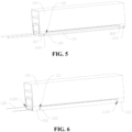
Fig. 5 is a schematic structural diagram of a blowing mechanism and a guide member in a drying apparatus according to another embodiment of the present application; -
Fig. 6 is a schematic structural diagram of a blowing mechanism and a guide member in a drying apparatus according to still another embodiment of the present application; -
Fig. 7 is a schematic structural diagram of an oven according to an embodiment of the present application; and -
Fig. 8 is a schematic structural diagram of an oven according to another embodiment of the present application. - Reference numerals in Detailed Description are as follows:
drying apparatus 100,blowing mechanism 110, air-outlet channel 111, first sub-air-outlet channel 1111,first air outlet 1111a, second sub-air-outlet channel 1112,second air outlet 1112a, first rotational connectingportion 112, first arc-shaped protrusion 1121, first connectinghole 1122, second rotational connectingportion 113, second arc-shaped protrusion 1131, second connectinghole 1132,guide member 120,rotation shaft 130,air box 140,opening 141,guide plate 150, meshes 151, adjustingmember 160,oven 10;material 200. - Examples of the technical solutions of the present application will be described in detail below in conjunction with the drawings. The following embodiments are only used to more clearly illustrate the technical solution of the present application, and therefore are only used as examples and cannot be used to limit the scope of protection of the present application.
- Unless otherwise defined, all technical and scientific terms used herein have the same meaning as commonly understood by those skilled in the art belonging to the technical field of the present application; the terms used herein are intended only for the purpose of describing specific examples and are not intended to limit the present application; the terms "including" and "having" and any variations thereof in the specification and the claims of the present application and in the description of drawings above are intended to cover non-exclusive inclusion.
- In the description of the embodiments of the present application, the technical terms "first", "second", and the like are used only to distinguish between different objects, and are not to be understood as indicating or implying a relative importance or implicitly specifying the number, particular order, or primary and secondary relation of the technical features indicated.
- Reference herein to "an embodiment" means that a particular feature, structure, or characteristic described in connection with the embodiment can be included in at least one embodiment of the present application. The appearance of this phrase in various places in the specification does not necessarily refer to the same embodiment, nor is it a separate or alternative embodiment that is mutually exclusive with other embodiments. It is explicitly and implicitly understood by those skilled in the art that the embodiments described herein may be combined with other embodiments.
- In the description of the embodiments of the present application, the term "and/or" is simply a description of an association of associated objects, which indicates that there may exist three relationships, for example, A and/or B may mean: the presence of A, the presence of both A and B, and the presence of B. In addition, the character "/" herein generally means that the associated objects before and after it are in an "or" relationship.
- In the description of the embodiments of the present application, the term "a plurality of" refers to two or more (including two), and similarly, "multiple groups" refers to two or more (including two) groups, and "multiple sheets" refers to two or more (including two) sheets.
- In the description of the embodiments of the present application, the orientation or position relationship indicated by the technical terms "center", "longitudinal", "transverse", "length", "width", "thickness", "upper", "lower", "front", "back", "left", "right", "vertical", "horizontal", "top", "bottom", "inner", "outer", "clockwise", "counterclockwise", "axial", "radial", "circumferential" etc. are based on the orientation or position relationship shown in the drawings and are intended to facilitate the description of the embodiments of the present application and simplify the description only, rather than indicating or implying that the device or element referred to must have a particular orientation or be constructed and operated in a particular orientation, and therefore are not to be interpreted as limitations on the embodiments of the present application.
- In the description of the embodiments of the present application, unless otherwise expressly specified and limited, the technical terms "mount", "join", "connect", "fix", etc. should be understood in a broad sense, such as, a fixed connection, a detachable connection, or an integral connection; a mechanical connection, or an electrical connection; a direct connection, an indirect connection through an intermediate medium, an internal connection of two elements, or interaction between two elements. For those of ordinary skill in the art, the specific meanings of the above terms in the embodiments of the present application can be understood according to specific situations.
- For drying apparatuses that perform drying by blowing air, areas of air outlets on some drying apparatuses are fixed, and the air speed or air volume cannot be adjusted adaptively, so the drying efficiency is low. Some drying apparatuses have wind shields in air flow channels. By moving the wind shield, the area of an air flow channel will be increased or decreased, thereby realizing the adjustment of the air speed and air volume. However, since the air volume will increase with the increase of the air speed and decrease with the decrease of the air speed, it is difficult to be adjusted to an appropriate position, thereby affecting the drying efficiency.
- Based on this, a drying apparatus is proposed in the present application. By movably arranging a guide member in an air-outlet channel of a blowing mechanism, the guide member can divide the air-outlet channel into a first sub-air-outlet channel and a second sub-air-outlet channel when moving. The guide member does not change the area of a section of the air-outlet channel, and is only used for dividing the air-outlet channel into two sub-channels; therefore, a total air output of the drying apparatus does not change. Air speeds of the first sub-air-outlet channel and the second sub-air-outlet channel may be changed correspondingly with the movement of the guide member, thereby realizing adjustment of the air speed without changing the air volume, and ensuring the drying efficiency of the drying apparatus for the material.
- According to one aspect of the embodiments of the present application, a drying apparatus for drying a material is provided. Specifically, referring to
Fig. 1 to Fig. 3 ,Fig. 1 shows a three-dimensional structure of dryingapparatus 100 according to an embodiment of the present application,Fig. 2 shows a three-dimensional structure ofblowing mechanism 110 and guidemember 120 in dryingapparatus 100 according to an embodiment, andFig. 3 shows a sectional structure of dryingapparatus 100 according to an embodiment.Drying apparatus 100 includesblowing mechanism 110 and guidemember 120. Theblowing mechanism 110 is provided with air-outlet channel 111, and air-outlet channel 111 is used for delivering dry gas tomaterial 200.Guide member 120 is movably arranged in air-outlet channel 111, and is used for dividing air-outlet channel 111 into first sub-air-outlet channel 1111 and second sub-air-outlet channel 1112.First air outlet 1111a of first sub-air-outlet channel 1111 andsecond air outlet 1112a of second sub-air-outlet channel 1112 both facematerial 200. - It should be noted that, in order to facilitate the display of the internal structure, the specific structure in
Fig. 1 andFig. 2 is a structure shown by dryingapparatus 100 after a part is cut off. In a specific product, both sides ofblowing mechanism 110 in dryingapparatus 100 inFig. 1 andFig. 2 with openings in a length direction ofguide member 120 are provided with complete side walls to ensure the closure of an internal gas flow channel ofblowing mechanism 110. -
Material 200 may be an electrode sheet substrate coated with a conductive material as shown inFig. 1 . Specifically, in the field of electrode sheet application batteries, after the conductive material is coated on the electrode sheet substrate, dryingapparatus 100 blows air to a substrate material, so that the conductive material is dried and adhered to the electrode sheet substrate to form an electrode sheet. The electrode sheet substrate may be, for example, a current collector. It is understandable thatmaterial 200 may also be a coated textile, a plastic structure, or the like. -
Blowing mechanism 110 may be an air knife as shown in the figure. The air knife may be driven by a vortex blower or a high-pressure centrifugal blower. After gas is compressed, it may be blown out at a high speed in the form of a thin airflow sheet with a smaller thickness to achieve the drying ofmaterial 200. -
Guide member 120 may be a plate structure.Guide member 120 may be rotationally arranged in air-outlet channel 111 as shown inFig. 3 , and a rotating direction is a direction shown by an arrow inFig. 3 , so that air-outlet channel 111 may be divided into first sub-air-outlet channel 1111 and second sub-air-outlet channel 1112 by rotatingguide member 120. - As shown in
Fig. 4 , the figure shows a sectional structure of dryingapparatus 100 according to an embodiment of the present application. As shown in the figure,guide member 120 may also be slidably arranged in air-outlet channel 111, and a sliding direction is a direction shown by an arrow inFig. 4 , so that air-outlet channel 111 may be divided into first sub-air-outlet channel 1111 and second sub-air-outlet channel 1112 by slidingguide member 120. - By movably arranging
guide member 120 in air-outlet channel 111 ofblowing mechanism 110,guide member 120 may divide air-outlet channel 111 into first sub-air-outlet channel 1111 and second sub-air-outlet channel 1112 when moving.Guide member 120 does not change the area of a section of air-outlet channel 111, and is only used for dividing air-outlet channel 111 into two sub-channels; therefore, a total air output of dryingapparatus 100 does not change. Opening areas and internal volumes of first sub-air-outlet channel 1111 and second sub-air-outlet channel 1112 may be changed correspondingly with the movement ofguide member 120, and therefore, air speeds in first sub-air-outlet channel 1111 and second sub-air-outlet channel 1112 may be changed, thereby realizing adjustment of the air speed without changing the air volume. At the same time,first air outlet 1111a of first sub-air-outlet channel 1111 andsecond air outlet 1112a of second sub-air-outlet channel 1112 are both arranged to facematerial 200, so that air flows from air-outlet channel 111 to first sub-air-outlet channel 1111 and second sub-air-outlet channel 1112 will eventually be blown tomaterial 200, thereby fully ensuring the drying efficiency of dryingapparatus 100 formaterial 200. - Referring to
Fig. 2 andFig. 3 again, in some embodiments of the present application,rotation shaft 130 is rotationally arranged in air-outlet channel 111,guide member 120 is fixed onrotation shaft 130, and when rotating withrotation shaft 130,guide member 120 changes air outputs offirst air outlet 1111a andsecond air outlet 1112a. - Specifically,
guide member 120 may be fixed on an annular side ofrotation shaft 130 by welding, androtation shaft 130 may be arranged on an outer side ofguide member 120 as shown in the figure.rotation shaft 130 andblowing mechanism 110 may not be connected, androtation shaft 130 may be connected to an external supporting structure (such as a supporting hole) after at least one end extending and projecting out of a surface of blowingmechanism 110, thereby realizing fixing ofrotation shaft 130 and guidemember 120 at a required position. - It may be understood that in some other embodiments,
rotation shaft 130 may also be arranged on an inner side ofguide member 120, and both ends ofrotation shaft 130 are rotationally connected to the side walls of blowing mechanism 110 (that is, side walls not drawn at both ends ofblowing mechanism 110 in a length direction ofguide member 120 or an axis direction ofrotation shaft 130 inFig. 1 andFig. 2 ). - A connecting hole may also be arranged on
guide member 120, androtation shaft 130 is penetrated into the connecting hole and fixedly connected to guidemember 120. - By rotationally arranging
rotation shaft 130 in air-outlet channel 111 and fixingguide member 120 onrotation shaft 130, convenient control ofguide member 120 may be achieved by rotatingrotation shaft 130 to adjust opening sizes of first sub-air-outlet channel 1111 and second sub-air-outlet channel 1112, so that the air outputs offirst air outlet 1111a andsecond air outlet 1112a may change inversely without changing the total air output, and corresponding adjustment may be performed according to actual requirements to achieve the best drying efficiency. - Referring to
Fig. 5 , which shows structures of first rotational connectingportion 112 and second rotational connectingportion 113 in dryingapparatus 100 according to an embodiment of the present application. In some embodiments of the present application,blowing mechanism 110 includes first rotational connectingportion 112 and second rotational connectingportion 113,guide member 120 is located between first rotational connectingportion 112 and second rotational connectingportion 113, androtation shaft 130 is rotationally connected to first rotational connectingportion 112 and second rotational connectingportion 113. - As shown in
Fig. 5 , first rotational connectingportion 112 and second rotational connectingportion 113 are parts on the shell ofblowing mechanism 110 located at both ends ofguide member 120. First rotational connectingportion 112 and second rotational connectingportion 113 may be provided with structures such as a bearing and a connecting hole, for being rotationally connected torotation shaft 130. - By arranging
guide member 120 between first rotational connectingportion 112 and second rotational connectingportion 113, and rotationally connectingrotation shaft 130 to first rotational connectingportion 112 and second rotational connectingportion 113,guide member 120 can be smoothly fixed on blowingmechanism 110 when it rotates to the desired position. - Still referring to
Fig. 5 , in some embodiments of the present application, a surface of first rotational connectingportion 112 protrudes to form first arc-shapedprotrusion 1121, a surface of second rotational connectingportion 113 protrudes to form second arc-shapedprotrusion 1131, first arc-shapedprotrusion 1121 and second arc-shapedprotrusion 1131 are arranged oppositely, androtation shaft 130 is rotationally arranged on first arc-shapedprotrusion 1121 and second arc-shapedprotrusion 1131 respectively. - First arc-shaped
protrusion 1121 and second arc-shapedprotrusion 1131 are arranged on first rotational connectingportion 112 and second rotational connectingportion 113 respectively, androtation shaft 130 is arranged on first arc-shapedprotrusion 1121 and second arc-shapedprotrusion 1131 respectively, so thatrotation shaft 130 and guidemember 120 can be conveniently placed on blowingmechanism 110 or taken off from blowingmechanism 110 under the support of first arc-shapedprotrusion 1121 and second arc-shapedprotrusion 1131, androtation shaft 130 and guidemember 120 can rotate smoothly for adjustment. - Referring to
Fig. 6 , which shows structures of first connectinghole 1122 and second connectinghole 1132 in dryingapparatus 100 according to an embodiment of the present application. In some embodiments of the present application, first rotational connectingportion 112 is provided with first connectinghole 1122, second rotational connectingportion 113 is provided with second connectinghole 1132, first connectinghole 1122 and second connectinghole 1132 are arranged oppositely, androtation shaft 130 is rotationally arranged in first connectinghole 1122 and second connectinghole 1132 respectively. - First connecting
hole 1122 and second connectinghole 1132 may be directly arranged on walls of first rotational connectingportion 112 and second rotational connectingportion 113 as shown inFig. 6 , or protrusions may be arranged oppositely on surfaces of first connectinghole 1122 and second connectinghole 1132, and first rotational connectingportion 112 and second rotational connectingportion 113 are arranged on the two opposite protrusions respectively. - First connecting
hole 1122 and second connectinghole 1132 may be both blind holes, or both through holes, or one blind hole and one through hole. - First connecting
hole 1122 and second connectinghole 1132 are arranged on first rotational connectingportion 112 and second rotational connectingportion 113 respectively, androtation shaft 130 is rotationally arranged in first connectinghole 1122 and second connectinghole 1132 respectively, so thatrotation shaft 130 and guidemember 120 are reliably connected to blowingmechanism 110, thereby ensuring the stability of the overall structure of dryingapparatus 100. - Referring to
Fig. 3 again, in some embodiments of the present application, an outer cover of second sub-air-outlet channel 1112 is provided withair box 140, one side ofair box 140 facingmaterial 200 is provided with anopening 141, andair box 140 is used for accommodating the gas blown from second sub-air-outlet channel 1112, so that the gas is blown tomaterial 200 from opening 141. - Specifically, opening 141 may be formed by hollowing out one side of
air box 140 facingmaterial 200 as shown inFig. 3 , or by opening a through hole on a side wall ofair box 140 facingmaterial 200. - By installing
air box 140 on the outer cover of second sub-air-outlet channel 1112, the gas blown from second sub-air-outlet channel 1112 is accommodated inair box 140, and by arrangingopening 141 on the side ofair box 140 facingmaterial 200, the gas accommodated inair box 140 may be smoothly blown tomaterial 200 throughopening 141, thereby ensuring the drying efficiency of dryingapparatus 100 formaterial 200. - Referring to
Fig. 1 again, in some embodiments of the present application,opening 141 is provided withguide plate 150, and guideplate 150 is provided with mesh 151. - As shown in
Fig. 1 , there may be a plurality of meshes 151 uniformly arranged onguide plate 150. Mesh 151 may be circular, elliptical, square, rhombic, polygonal, or the like, which is not limited here. - By arranging
guide plate 150 at opening 141 and arranging mesh 151 onguide plate 150, mesh 151 can provide uniform dispersion and guidance for the gas inair box 140. Specifically, mesh 151 evenly disperses the gas inair box 140 into different holes and guides the gas to blow tomaterial 200, so that the air flow on the surface ofmaterial 200 is more uniform, which is conducive to ensuring the uniformity of the drying degree of the surface ofmaterial 200. - Still referring to
Fig. 1 , in some embodiments of the present application, one end ofrotation shaft 130 is provided with adjustingmember 160. - Specifically, adjusting
member 160 may be a knob cover sleeved onrotation shaft 130, and guidemember 120 may be adjusted by rotating the knob cover. Adjustingmember 160 may also be a motor connected to one end ofrotation shaft 130, and the motor drivesrotation shaft 130 to rotate to realize the adjustment ofguide member 120. On the basis of the above two specific embodiments, adjustingmember 160 may also include a gear set, and the knob cover or motor may be connected torotation shaft 130 through the gear set to achieve acceleration or deceleration, so that the adjustment is more labor-saving or more accurate. - By arranging adjusting
member 160 at one end ofrotation shaft 130, it is more convenient for controlling and adjustingguide member 120. - According to another aspect of the embodiments of the present application, an oven is provided. Specifically, referring to
Fig. 7 , it shows a structure ofoven 10 according to an embodiment of the present application. As shown in the figure,oven 10 includes dryingapparatus 100. There are a plurality of dryingapparatuses 100, and the plurality of dryingapparatuses 100 are arranged in a preset direction. - In the specific embodiment shown in
Fig. 7 , the preset direction is a direction shown by an arrow in the figure, and whenmaterial 200 is an electrode sheet substrate coated with a conductive material, the preset direction may be a delivering direction of feeding and drying the electrode sheet substrate. It should be noted that in other embodiments, the preset direction may be any direction, and a corresponding design may be made specifically according to a product shape or structural characteristics of the material to be dried, which will not be repeated here. - In a production line, the plurality of drying
apparatuses 100 may be connected to the same air supply pipeline to reduce space occupation, and optimize the layout of the production line. Moreover, each dryingapparatus 100 inoven 10 may be individually adjusted throughguide member 120 to achieve the optimal drying effect. - In
oven 10 provided in the present application, by movably arrangingguide member 120 in air-outlet channel 111 ofblowing mechanism 110,guide member 120 may divide air-outlet channel 111 into first sub-air-outlet channel 1111 and second sub-air-outlet channel 1112 when moving.Guide member 120 does not change the area of a section of air-outlet channel 111, and is only used for dividing air-outlet channel 111 into two sub-channels; therefore, a total air output of dryingapparatus 100 does not change. Opening areas and internal volumes of first sub-air-outlet channel 1111 and second sub-air-outlet channel 1112 may be changed correspondingly with the movement ofguide member 120, and therefore, air speeds in first sub-air-outlet channel 1111 and second sub-air-outlet channel 1112 may be changed, thereby realizing adjustment of the air speed without changing the air volume. At the same time,first air outlet 1111a of first sub-air-outlet channel 1111 andsecond air outlet 1112a of second sub-air-outlet channel 1112 are both arranged to facematerial 200, so that air flows from air-outlet channel 111 to first sub-air-outlet channel 1111 and second sub-air-outlet channel 1112 will eventually be blown tomaterial 200, thereby fully ensuring the drying efficiency ofoven 10 formaterial 200. - Referring to Fig. 10, which shows a structure of an oven according to another embodiment. In some embodiments of the present application,
air boxes 140 are arranged on both sides of a plurality of dryingapparatuses 100 in a preset direction, andair boxes 140 between adjacent dryingapparatuses 100 communicate with each other. - By arranging
air boxes 140 on both sides of the plurality of dryingapparatuses 100 in the preset direction, and communicatingair boxes 140 between adjacent dryingapparatuses 100, a space occupied by a wall ofair box 140 in the preset direction is eliminated, space occupation ofoven 10 is effectively reduced, a structural layout ofoven 10 is optimized, and full coverage of blowing in the preset direction is realized, which can fully improve the drying efficiency. - The description of the invention is supplemented by the following numbered clauses, which are not to be taken as claims.
- Clause 1: A drying apparatus (100) for drying a material (200), comprising: a blowing mechanism (110) having an air-outlet channel (111) for conveying dry gas to the material (200); and a guide member (120) movably arranged in the air-outlet channel (111) and used for dividing the air-outlet channel (111) into a first sub-air-outlet channel (1111) and a second sub-air-outlet channel (1112), a first air outlet (11 11a) of the first sub-air-outlet channel (1111) and a second air outlet (1112a) of the second sub-air-outlet channel (1112) both facing the material (200).
- Clause 2: The drying apparatus (100) according to clause 1, wherein a rotation shaft (130) is rotationally arranged in the air-outlet channel (111), the guide member (120) is fixed on the rotation shaft (130), and when rotating with the rotation shaft (130), the guide member (120) changes air outputs of the first air outlet (11 11a) and the second air outlet (1112a).
- Clause 3: The drying apparatus (100) according to clause 2, wherein the blowing mechanism (110) comprises a first rotational connecting portion (112) and a second rotational connecting portion (113) arranged oppositely, the guide member (120) is located between the first rotational connecting portion (112) and the second rotational connecting portion (113), and the rotation shaft (130) is rotationally connected to the first rotational connecting portion (112) and the second rotational connecting portion (113).
- Clause 4: The drying apparatus (100) according to clause 3, wherein a surface of the first rotational connecting portion (112) protrudes to form a first arc-shaped protrusion (1121), a surface of the second rotational connecting portion (113) protrudes to form a second arc-shaped protrusion (1131), the first arc-shaped protrusion (1121) and the second arc-shaped protrusion (1131) are arranged oppositely, and the rotation shaft (130) is rotationally arranged on the first arc-shaped protrusion (1121) and the second arc-shaped protrusion (1131) respectively.
- Clause 5: The drying apparatus (100) according to clause 3, wherein the first rotational connecting portion (112) is provided with a first connecting hole (1122), the second rotational connecting portion (113) is provided with a second connecting hole (1132), the first connecting hole (1122) and the second connecting hole (1132) are arranged oppositely, and the rotation shaft (130) is rotationally arranged in the first connecting hole (1122) and the second connecting hole (1132) respectively.
- Clause 6: The drying apparatus (100) according to any of clauses 1 to 5, wherein an outer cover of the second sub-air-outlet channel (1112) is provided with an air box (140), one side of the air box (140) facing the material (200) is provided with an opening (141), and the air box (140) is used for accommodating the gas blown from the second sub-air-outlet channel (1112), so that the gas is blown to the material (200) from the opening (141).
- Clause 7: The drying apparatus (100) according to clause 6, wherein the opening (141) is provided with a guide plate (150), and the guide plate (150) is provided with meshes (151).
- Clause 8: The drying apparatus (100) according to any one of clauses 2 to 7, wherein one end of the rotation shaft (130) is provided with an adjusting member (160).
- Clause 9: An oven (10), comprising the drying apparatus (100) according to any one of clauses 1 to 8, wherein there are a plurality of drying apparatuses (100), and the plurality of drying apparatuses (100) are arranged in a preset direction.
- Clause 10: The oven (10) according to clause 9, wherein air boxes (140) are arranged on both sides of the plurality of drying apparatuses (100) in the preset direction, and the air boxes (140) between adjacent drying apparatuses (100) are in communication with each other.
- Finally, it should be noted that the above embodiments are merely used for illustrating rather than limiting the technical solutions of the present utility model. Although the present utility model has been described in detail with reference to the above various embodiments, those of ordinary skill in the art should understood that the technical solutions specified in the above various embodiments can still be modified, or some or all of the technical features therein can be equivalently substituted; and such modifications or substitutions do not make the essence of the corresponding technical solutions depart from the scope of the technical solutions of the various embodiments of the present utility model, and shall fall within the scope of the claims of the specification of the present utility model. In particular, the technical features mentioned in the various examples can be combined in any manner as long as there is no structural conflict. The present utility model is not limited to the specific embodiments disclosed herein, but rather includes all technical solutions falling within the scope of the claims.
Claims (6)
- A drying apparatus (100) for drying a material (200), comprising:a blowing mechanism (110) having an air-outlet channel (111) for conveying dry gas to the material (200); anda guide member (120) movably arranged in the air-outlet channel (111) and used for dividing the air-outlet channel (111) into a first sub-air-outlet channel (1111) and a second sub-air-outlet channel (1112), a first air outlet (1111a) of the first sub-air-outlet channel (1111) and a second air outlet (1112a) of the second sub-air-outlet channel (1112) both facing the material (200),wherein a rotation shaft (130) is rotationally arranged in the air-outlet channel (111), the guide member (120) is fixed on the rotation shaft (130), and when rotating with the rotation shaft (130), the guide member (120) changes air outputs of the first air outlet (1111a) and the second air outlet (1112a), and wherein the blowing mechanism (110) comprises a first rotational connecting portion (112) and a second rotational connecting portion (113) arranged oppositely, the guide member (120) is located between the first rotational connecting portion (112) and the second rotational connecting portion (113), and the rotation shaft (130) is rotationally connected to the first rotational connecting portion (112) and the second rotational connecting portion (113); the drying apparatus being characterized in that the first rotational connecting portion (112) is provided with a first connecting hole (1122), the second rotational connecting portion (113) is provided with a second connecting hole (1132), the first connecting hole (1122) and the second connecting hole (1132) are arranged oppositely, and the rotation shaft (130) is rotationally arranged in the first connecting hole (1122) and the second connecting hole (1132) respectively.
- The drying apparatus (100) according to claim 1, wherein an outer cover of the second sub-air-outlet channel (1112) is provided with an air box (140), one side of the air box (140) facing the material (200) is provided with an opening (141), and the air box (140) is used for accommodating the gas blown from the second sub-air-outlet channel (1112), so that the gas is blown to the material (200) from the opening (141).
- The drying apparatus (100) according to claim 2, wherein the opening (141) is provided with a guide plate (150), and the guide plate (150) is provided with meshes (151).
- The drying apparatus (100) according to any one of claims 1 to 3, wherein one end of the rotation shaft (130) is provided with an adjusting member (160).
- An oven (10), comprising the drying apparatus (100) according to any one of claims 1 to 4, wherein there are a plurality of drying apparatuses (100), and the plurality of drying apparatuses (100) are arranged in a preset direction.
- The oven (10) according to claim 5, wherein air boxes (140) are arranged on both sides of the blowing mechanism (110) of the plurality of drying apparatuses (100) in the preset direction, and the air boxes (140) between adjacent blowing mechanisms (110) are in communication with each other.
Applications Claiming Priority (2)
| Application Number | Priority Date | Filing Date | Title |
|---|---|---|---|
| CN202220401766.0U CN217154922U (en) | 2022-02-25 | 2022-02-25 | Drying device and oven |
| EP23158512.6A EP4235071B1 (en) | 2022-02-25 | 2023-02-24 | Drying apparatus and oven |
Related Parent Applications (2)
| Application Number | Title | Priority Date | Filing Date |
|---|---|---|---|
| EP23158512.6A Division EP4235071B1 (en) | 2022-02-25 | 2023-02-24 | Drying apparatus and oven |
| EP23158512.6A Division-Into EP4235071B1 (en) | 2022-02-25 | 2023-02-24 | Drying apparatus and oven |
Publications (3)
| Publication Number | Publication Date |
|---|---|
| EP4474742A2 true EP4474742A2 (en) | 2024-12-11 |
| EP4474742A3 EP4474742A3 (en) | 2025-03-12 |
| EP4474742B1 EP4474742B1 (en) | 2025-11-05 |
Family
ID=82691188
Family Applications (2)
| Application Number | Title | Priority Date | Filing Date |
|---|---|---|---|
| EP23158512.6A Active EP4235071B1 (en) | 2022-02-25 | 2023-02-24 | Drying apparatus and oven |
| EP24209300.3A Active EP4474742B1 (en) | 2022-02-25 | 2023-02-24 | Drying apparatus and oven |
Family Applications Before (1)
| Application Number | Title | Priority Date | Filing Date |
|---|---|---|---|
| EP23158512.6A Active EP4235071B1 (en) | 2022-02-25 | 2023-02-24 | Drying apparatus and oven |
Country Status (5)
| Country | Link |
|---|---|
| US (1) | US12607405B2 (en) |
| EP (2) | EP4235071B1 (en) |
| CN (1) | CN217154922U (en) |
| ES (2) | ES3060033T3 (en) |
| HU (1) | HUE069910T2 (en) |
Families Citing this family (3)
| Publication number | Priority date | Publication date | Assignee | Title |
|---|---|---|---|---|
| CN221549254U (en) * | 2023-09-28 | 2024-08-16 | 宁德时代新能源科技股份有限公司 | Ventilating device |
| CN117387315B (en) * | 2023-10-18 | 2025-10-03 | 河北金力新能源科技股份有限公司 | A suction mechanism for recovering oven leaked gas |
| CN120627614B (en) * | 2025-08-11 | 2025-11-14 | 中胶(内蒙古)新材料有限责任公司 | Air quantity intelligent regulation device and oven |
Citations (3)
| Publication number | Priority date | Publication date | Assignee | Title |
|---|---|---|---|---|
| CN208108724U (en) | 2018-02-11 | 2018-11-16 | 广州市创坤金葱粉皮革有限公司 | A kind of ground drying unit |
| CN210242218U (en) | 2019-08-12 | 2020-04-03 | 临朐县钰坤机械设备厂 | Drying box with angle-adjustable air distribution plate |
| CN212157928U (en) | 2020-10-26 | 2020-12-15 | 广东三技克朗茨机械科技有限公司 | Drying machine |
Family Cites Families (10)
| Publication number | Priority date | Publication date | Assignee | Title |
|---|---|---|---|---|
| US6182374B1 (en) * | 1999-12-16 | 2001-02-06 | Chin-Pei Yen | Drying machine |
| KR20090082891A (en) | 2006-10-18 | 2009-07-31 | 에이전시 포 사이언스, 테크놀로지 앤드 리서치 | Method of functionalizing a carbon material |
| US10294642B2 (en) * | 2011-04-18 | 2019-05-21 | Bradley Fixtures Corporation | Lavatory system with integrated hand dryer |
| KR101229347B1 (en) | 2012-09-05 | 2013-02-05 | 일성기계공업 주식회사 | Hot air spray nozzle for tenter machine and hot air sprayer for tenter machine |
| WO2015059261A1 (en) * | 2013-10-24 | 2015-04-30 | Spx Flow Technology Danmark A/S | Gas distributer for a convective dryer having improved radial gas velocity control |
| JP2015210931A (en) | 2014-04-25 | 2015-11-24 | 株式会社豊田自動織機 | Binder for negative electrode of secondary battery, negative electrode of secondary battery and secondary battery |
| CN111219956B (en) | 2018-11-27 | 2023-05-23 | 青岛海高设计制造有限公司 | Dryer and its control method |
| KR102902310B1 (en) | 2018-12-18 | 2025-12-22 | 도아고세이가부시키가이샤 | Binder for secondary battery electrode and its use |
| WO2020218049A1 (en) | 2019-04-26 | 2020-10-29 | 東亞合成株式会社 | Secondary battery electrode binder and use therefor |
| CN211660405U (en) | 2019-10-17 | 2020-10-13 | 深圳市新嘉拓自动化技术有限公司 | A Novel Air Nozzle Structure of Suspended Oven of Coating Machine |
-
2022
- 2022-02-25 CN CN202220401766.0U patent/CN217154922U/en active Active
-
2023
- 2023-02-23 US US18/173,747 patent/US12607405B2/en active Active
- 2023-02-24 HU HUE23158512A patent/HUE069910T2/en unknown
- 2023-02-24 EP EP23158512.6A patent/EP4235071B1/en active Active
- 2023-02-24 EP EP24209300.3A patent/EP4474742B1/en active Active
- 2023-02-24 ES ES24209300T patent/ES3060033T3/en active Active
- 2023-02-24 ES ES23158512T patent/ES3013068T3/en active Active
Patent Citations (3)
| Publication number | Priority date | Publication date | Assignee | Title |
|---|---|---|---|---|
| CN208108724U (en) | 2018-02-11 | 2018-11-16 | 广州市创坤金葱粉皮革有限公司 | A kind of ground drying unit |
| CN210242218U (en) | 2019-08-12 | 2020-04-03 | 临朐县钰坤机械设备厂 | Drying box with angle-adjustable air distribution plate |
| CN212157928U (en) | 2020-10-26 | 2020-12-15 | 广东三技克朗茨机械科技有限公司 | Drying machine |
Also Published As
| Publication number | Publication date |
|---|---|
| US20230272975A1 (en) | 2023-08-31 |
| EP4235071A1 (en) | 2023-08-30 |
| ES3013068T3 (en) | 2025-04-10 |
| HUE069910T2 (en) | 2025-04-28 |
| EP4474742A3 (en) | 2025-03-12 |
| US12607405B2 (en) | 2026-04-21 |
| EP4474742B1 (en) | 2025-11-05 |
| ES3060033T3 (en) | 2026-03-24 |
| EP4235071B1 (en) | 2024-12-04 |
| CN217154922U (en) | 2022-08-09 |
| EP4235071C0 (en) | 2024-12-04 |
Similar Documents
| Publication | Publication Date | Title |
|---|---|---|
| EP4474742A2 (en) | Drying apparatus and oven | |
| WO2021051895A1 (en) | Indoor unit, air conditioner, and air conditioner control method | |
| CN107166514A (en) | Indoor apparatus of air conditioner | |
| CN103673466A (en) | Centrifugal fan refrigerator air duct structure and refrigerator | |
| CN217031376U (en) | Indoor unit of air conditioner and air conditioner | |
| CN217031378U (en) | Indoor unit of air conditioner and air conditioner | |
| CN110469911A (en) | Indoor unit and air conditioner with it | |
| CN210861594U (en) | Air duct assembly and air conditioner with same | |
| CN107842918A (en) | Ceiling machine | |
| CN114135939A (en) | Ceiling machine | |
| CN111380198A (en) | An air guide mechanism and an air conditioner | |
| CN112303728A (en) | Cabinet air conditioner and control method | |
| CN114087754A (en) | Air duct components, indoor units and air conditioners | |
| CN210118847U (en) | Air conditioner indoor unit | |
| CN216620226U (en) | Air duct component, indoor unit and air conditioner | |
| JPH09210440A (en) | Induction type variable constant air volume device | |
| CN111306625A (en) | Air conditioner | |
| CN217031380U (en) | Air supply barrel for air conditioner and air conditioner | |
| CN217274489U (en) | Air supply barrel assembly for air conditioner and air conditioner | |
| CN110207259A (en) | Air conditioner indoor unit | |
| CN114838408A (en) | Air supply mechanism and air conditioner with same | |
| CN212227361U (en) | Air conditioner | |
| CN212253113U (en) | Base and cabinet air conditioner | |
| CN213514112U (en) | Air conditioner cabinet | |
| CN211146687U (en) | Indoor unit and air conditioner with same |
Legal Events
| Date | Code | Title | Description |
|---|---|---|---|
| PUAI | Public reference made under article 153(3) epc to a published international application that has entered the european phase |
Free format text: ORIGINAL CODE: 0009012 |
|
| STAA | Information on the status of an ep patent application or granted ep patent |
Free format text: STATUS: THE APPLICATION HAS BEEN PUBLISHED |
|
| AC | Divisional application: reference to earlier application |
Ref document number: 4235071 Country of ref document: EP Kind code of ref document: P |
|
| AK | Designated contracting states |
Kind code of ref document: A2 Designated state(s): AL AT BE BG CH CY CZ DE DK EE ES FI FR GB GR HR HU IE IS IT LI LT LU LV MC ME MK MT NL NO PL PT RO RS SE SI SK SM TR |
|
| PUAL | Search report despatched |
Free format text: ORIGINAL CODE: 0009013 |
|
| AK | Designated contracting states |
Kind code of ref document: A3 Designated state(s): AL AT BE BG CH CY CZ DE DK EE ES FI FR GB GR HR HU IE IS IT LI LT LU LV MC ME MK MT NL NO PL PT RO RS SE SI SK SM TR |
|
| RIC1 | Information provided on ipc code assigned before grant |
Ipc: F26B 21/12 20060101AFI20250204BHEP |
|
| STAA | Information on the status of an ep patent application or granted ep patent |
Free format text: STATUS: REQUEST FOR EXAMINATION WAS MADE |
|
| 17P | Request for examination filed |
Effective date: 20250327 |
|
| GRAP | Despatch of communication of intention to grant a patent |
Free format text: ORIGINAL CODE: EPIDOSNIGR1 |
|
| STAA | Information on the status of an ep patent application or granted ep patent |
Free format text: STATUS: GRANT OF PATENT IS INTENDED |
|
| INTG | Intention to grant announced |
Effective date: 20250811 |
|
| GRAS | Grant fee paid |
Free format text: ORIGINAL CODE: EPIDOSNIGR3 |
|
| GRAA | (expected) grant |
Free format text: ORIGINAL CODE: 0009210 |
|
| STAA | Information on the status of an ep patent application or granted ep patent |
Free format text: STATUS: THE PATENT HAS BEEN GRANTED |
|
| AC | Divisional application: reference to earlier application |
Ref document number: 4235071 Country of ref document: EP Kind code of ref document: P |
|
| AK | Designated contracting states |
Kind code of ref document: B1 Designated state(s): AL AT BE BG CH CY CZ DE DK EE ES FI FR GB GR HR HU IE IS IT LI LT LU LV MC ME MK MT NL NO PL PT RO RS SE SI SK SM TR |
|
| REG | Reference to a national code |
Ref country code: CH Ref legal event code: F10 Free format text: ST27 STATUS EVENT CODE: U-0-0-F10-F00 (AS PROVIDED BY THE NATIONAL OFFICE) Effective date: 20251105 Ref country code: GB Ref legal event code: FG4D |
|
| REG | Reference to a national code |
Ref country code: DE Ref legal event code: R096 Ref document number: 602023008411 Country of ref document: DE |
|
| REG | Reference to a national code |
Ref country code: DE Ref legal event code: R079 Ref document number: 602023008411 Country of ref document: DE Free format text: PREVIOUS MAIN CLASS: F26B0021120000 Ipc: F26B0021370000 |
|
| REG | Reference to a national code |
Ref country code: IE Ref legal event code: FG4D |
|
| REG | Reference to a national code |
Ref country code: NL Ref legal event code: FP |
|
| P01 | Opt-out of the competence of the unified patent court (upc) registered |
Free format text: CASE NUMBER: UPC_APP_0003299_4474742/2026 Effective date: 20260129 |
|
| PGFP | Annual fee paid to national office [announced via postgrant information from national office to epo] |
Ref country code: NL Payment date: 20260220 Year of fee payment: 4 |
|
| REG | Reference to a national code |
Ref country code: ES Ref legal event code: FG2A Ref document number: 3060033 Country of ref document: ES Kind code of ref document: T3 Effective date: 20260324 |
|
| PGFP | Annual fee paid to national office [announced via postgrant information from national office to epo] |
Ref country code: ES Payment date: 20260303 Year of fee payment: 4 |
|
| REG | Reference to a national code |
Ref country code: LT Ref legal event code: MG9D |
|
| PG25 | Lapsed in a contracting state [announced via postgrant information from national office to epo] |
Ref country code: NO Free format text: LAPSE BECAUSE OF FAILURE TO SUBMIT A TRANSLATION OF THE DESCRIPTION OR TO PAY THE FEE WITHIN THE PRESCRIBED TIME-LIMIT Effective date: 20260205 |
|
| PGFP | Annual fee paid to national office [announced via postgrant information from national office to epo] |
Ref country code: DE Payment date: 20260223 Year of fee payment: 4 |
|
| PG25 | Lapsed in a contracting state [announced via postgrant information from national office to epo] |
Ref country code: FI Free format text: LAPSE BECAUSE OF FAILURE TO SUBMIT A TRANSLATION OF THE DESCRIPTION OR TO PAY THE FEE WITHIN THE PRESCRIBED TIME-LIMIT Effective date: 20251105 Ref country code: AT Free format text: LAPSE BECAUSE OF FAILURE TO SUBMIT A TRANSLATION OF THE DESCRIPTION OR TO PAY THE FEE WITHIN THE PRESCRIBED TIME-LIMIT Effective date: 20251105 Ref country code: HR Free format text: LAPSE BECAUSE OF FAILURE TO SUBMIT A TRANSLATION OF THE DESCRIPTION OR TO PAY THE FEE WITHIN THE PRESCRIBED TIME-LIMIT Effective date: 20251105 |
|
| PGFP | Annual fee paid to national office [announced via postgrant information from national office to epo] |
Ref country code: AT Payment date: 20260301 Year of fee payment: 4 |
|
| REG | Reference to a national code |
Ref country code: AT Ref legal event code: MK05 Ref document number: 1854754 Country of ref document: AT Kind code of ref document: T Effective date: 20251105 |
|
| PG25 | Lapsed in a contracting state [announced via postgrant information from national office to epo] |
Ref country code: RS Free format text: LAPSE BECAUSE OF FAILURE TO SUBMIT A TRANSLATION OF THE DESCRIPTION OR TO PAY THE FEE WITHIN THE PRESCRIBED TIME-LIMIT Effective date: 20260205 |
|
| PG25 | Lapsed in a contracting state [announced via postgrant information from national office to epo] |
Ref country code: IS Free format text: LAPSE BECAUSE OF FAILURE TO SUBMIT A TRANSLATION OF THE DESCRIPTION OR TO PAY THE FEE WITHIN THE PRESCRIBED TIME-LIMIT Effective date: 20260305 |
|
| PGFP | Annual fee paid to national office [announced via postgrant information from national office to epo] |
Ref country code: FR Payment date: 20260224 Year of fee payment: 4 |
|
| PG25 | Lapsed in a contracting state [announced via postgrant information from national office to epo] |
Ref country code: PT Free format text: LAPSE BECAUSE OF FAILURE TO SUBMIT A TRANSLATION OF THE DESCRIPTION OR TO PAY THE FEE WITHIN THE PRESCRIBED TIME-LIMIT Effective date: 20260305 |
|
| PG25 | Lapsed in a contracting state [announced via postgrant information from national office to epo] |
Ref country code: PL Free format text: LAPSE BECAUSE OF FAILURE TO SUBMIT A TRANSLATION OF THE DESCRIPTION OR TO PAY THE FEE WITHIN THE PRESCRIBED TIME-LIMIT Effective date: 20251105 |
|
| PG25 | Lapsed in a contracting state [announced via postgrant information from national office to epo] |
Ref country code: LV Free format text: LAPSE BECAUSE OF FAILURE TO SUBMIT A TRANSLATION OF THE DESCRIPTION OR TO PAY THE FEE WITHIN THE PRESCRIBED TIME-LIMIT Effective date: 20251105 |