EP4474658A1 - Wandankeranordnung - Google Patents
Wandankeranordnung Download PDFInfo
- Publication number
- EP4474658A1 EP4474658A1 EP23177707.9A EP23177707A EP4474658A1 EP 4474658 A1 EP4474658 A1 EP 4474658A1 EP 23177707 A EP23177707 A EP 23177707A EP 4474658 A1 EP4474658 A1 EP 4474658A1
- Authority
- EP
- European Patent Office
- Prior art keywords
- wall anchor
- wall
- mounting element
- anchor
- section
- Prior art date
- Legal status (The legal status is an assumption and is not a legal conclusion. Google has not performed a legal analysis and makes no representation as to the accuracy of the status listed.)
- Granted
Links
Images




Classifications
-
- F—MECHANICAL ENGINEERING; LIGHTING; HEATING; WEAPONS; BLASTING
- F16—ENGINEERING ELEMENTS AND UNITS; GENERAL MEASURES FOR PRODUCING AND MAINTAINING EFFECTIVE FUNCTIONING OF MACHINES OR INSTALLATIONS; THERMAL INSULATION IN GENERAL
- F16B—DEVICES FOR FASTENING OR SECURING CONSTRUCTIONAL ELEMENTS OR MACHINE PARTS TOGETHER, e.g. NAILS, BOLTS, CIRCLIPS, CLAMPS, CLIPS OR WEDGES; JOINTS OR JOINTING
- F16B5/00—Joining sheets or plates, e.g. panels, to one another or to strips or bars parallel to them
- F16B5/06—Joining sheets or plates, e.g. panels, to one another or to strips or bars parallel to them by means of clamps or clips
- F16B5/0607—Joining sheets or plates, e.g. panels, to one another or to strips or bars parallel to them by means of clamps or clips joining sheets or plates to each other
- F16B5/0621—Joining sheets or plates, e.g. panels, to one another or to strips or bars parallel to them by means of clamps or clips joining sheets or plates to each other in parallel relationship
- F16B5/0657—Joining sheets or plates, e.g. panels, to one another or to strips or bars parallel to them by means of clamps or clips joining sheets or plates to each other in parallel relationship at least one of the plates providing a raised structure, e.g. of the doghouse type, for connection with the clamps or clips of the other plate
-
- F—MECHANICAL ENGINEERING; LIGHTING; HEATING; WEAPONS; BLASTING
- F16—ENGINEERING ELEMENTS AND UNITS; GENERAL MEASURES FOR PRODUCING AND MAINTAINING EFFECTIVE FUNCTIONING OF MACHINES OR INSTALLATIONS; THERMAL INSULATION IN GENERAL
- F16B—DEVICES FOR FASTENING OR SECURING CONSTRUCTIONAL ELEMENTS OR MACHINE PARTS TOGETHER, e.g. NAILS, BOLTS, CIRCLIPS, CLAMPS, CLIPS OR WEDGES; JOINTS OR JOINTING
- F16B5/00—Joining sheets or plates, e.g. panels, to one another or to strips or bars parallel to them
- F16B5/06—Joining sheets or plates, e.g. panels, to one another or to strips or bars parallel to them by means of clamps or clips
- F16B5/0607—Joining sheets or plates, e.g. panels, to one another or to strips or bars parallel to them by means of clamps or clips joining sheets or plates to each other
- F16B5/0621—Joining sheets or plates, e.g. panels, to one another or to strips or bars parallel to them by means of clamps or clips joining sheets or plates to each other in parallel relationship
- F16B5/0664—Joining sheets or plates, e.g. panels, to one another or to strips or bars parallel to them by means of clamps or clips joining sheets or plates to each other in parallel relationship at least one of the sheets or plates having integrally formed or integrally connected snap-in-features
-
- E—FIXED CONSTRUCTIONS
- E03—WATER SUPPLY; SEWERAGE
- E03C—DOMESTIC PLUMBING INSTALLATIONS FOR FRESH WATER OR WASTE WATER; SINKS
- E03C1/00—Domestic plumbing installations for fresh water or waste water; Sinks
- E03C1/12—Plumbing installations for waste water; Basins or fountains connected thereto; Sinks
- E03C1/32—Holders or supports for basins
-
- E—FIXED CONSTRUCTIONS
- E03—WATER SUPPLY; SEWERAGE
- E03D—WATER-CLOSETS OR URINALS WITH FLUSHING DEVICES; FLUSHING VALVES THEREFOR
- E03D11/00—Other component parts of water-closets, e.g. noise-reducing means in the flushing system, flushing pipes mounted in the bowl, seals for the bowl outlet, devices preventing overflow of the bowl contents; devices forming a water seal in the bowl after flushing, devices eliminating obstructions in the bowl outlet or preventing backflow of water and excrements from the waterpipe
- E03D11/13—Parts or details of bowls; Special adaptations of pipe joints or couplings for use with bowls, e.g. provisions in bowl construction preventing backflow of waste-water from the bowl in the flushing pipe or cistern, provisions for a secondary flushing, for noise-reducing
- E03D11/14—Means for connecting the bowl to the wall, e.g. to a wall outlet
- E03D11/143—Mounting frames for toilets and urinals
-
- F—MECHANICAL ENGINEERING; LIGHTING; HEATING; WEAPONS; BLASTING
- F16—ENGINEERING ELEMENTS AND UNITS; GENERAL MEASURES FOR PRODUCING AND MAINTAINING EFFECTIVE FUNCTIONING OF MACHINES OR INSTALLATIONS; THERMAL INSULATION IN GENERAL
- F16B—DEVICES FOR FASTENING OR SECURING CONSTRUCTIONAL ELEMENTS OR MACHINE PARTS TOGETHER, e.g. NAILS, BOLTS, CIRCLIPS, CLAMPS, CLIPS OR WEDGES; JOINTS OR JOINTING
- F16B21/00—Means for preventing relative axial movement of a pin, spigot, shaft or the like and a member surrounding it; Stud-and-socket releasable fastenings
- F16B21/06—Releasable fastening devices with snap-action
- F16B21/07—Releasable fastening devices with snap-action in which the socket has a resilient part
- F16B21/071—Releasable fastening devices with snap-action in which the socket has a resilient part the socket being integrally formed with a component to be fasted, e.g. a sheet, plate or strip
-
- F—MECHANICAL ENGINEERING; LIGHTING; HEATING; WEAPONS; BLASTING
- F16—ENGINEERING ELEMENTS AND UNITS; GENERAL MEASURES FOR PRODUCING AND MAINTAINING EFFECTIVE FUNCTIONING OF MACHINES OR INSTALLATIONS; THERMAL INSULATION IN GENERAL
- F16B—DEVICES FOR FASTENING OR SECURING CONSTRUCTIONAL ELEMENTS OR MACHINE PARTS TOGETHER, e.g. NAILS, BOLTS, CIRCLIPS, CLAMPS, CLIPS OR WEDGES; JOINTS OR JOINTING
- F16B21/00—Means for preventing relative axial movement of a pin, spigot, shaft or the like and a member surrounding it; Stud-and-socket releasable fastenings
- F16B21/06—Releasable fastening devices with snap-action
- F16B21/07—Releasable fastening devices with snap-action in which the socket has a resilient part
- F16B21/073—Releasable fastening devices with snap-action in which the socket has a resilient part the socket having a resilient part on its inside
- F16B21/075—Releasable fastening devices with snap-action in which the socket has a resilient part the socket having a resilient part on its inside the socket having resilient parts on its inside and outside
-
- F—MECHANICAL ENGINEERING; LIGHTING; HEATING; WEAPONS; BLASTING
- F16—ENGINEERING ELEMENTS AND UNITS; GENERAL MEASURES FOR PRODUCING AND MAINTAINING EFFECTIVE FUNCTIONING OF MACHINES OR INSTALLATIONS; THERMAL INSULATION IN GENERAL
- F16B—DEVICES FOR FASTENING OR SECURING CONSTRUCTIONAL ELEMENTS OR MACHINE PARTS TOGETHER, e.g. NAILS, BOLTS, CIRCLIPS, CLAMPS, CLIPS OR WEDGES; JOINTS OR JOINTING
- F16B21/00—Means for preventing relative axial movement of a pin, spigot, shaft or the like and a member surrounding it; Stud-and-socket releasable fastenings
- F16B21/06—Releasable fastening devices with snap-action
- F16B21/08—Releasable fastening devices with snap-action in which the stud, pin, or spigot has a resilient part
- F16B21/088—Releasable fastening devices with snap-action in which the stud, pin, or spigot has a resilient part the stud, pin or spigot being integrally formed with the component to be fastened, e.g. forming part of the sheet, plate or strip
Definitions
- the present invention relates to a wall anchor arrangement, in particular for fastening a mounting frame of a sanitary article arrangement, according to claim 1 and an arrangement according to claim 15.
- Mounting frames for storing sanitary items are known from the state of the art. Such mounting frames are typically attached to a solid supporting structure, such as a building wall, using an anchor screw and a wall anchor.
- the DE 299 16 234 U1 discloses a quick fastening in which a C-rail is attached to a wall.
- An angle bracket is connected to the C-rail via a screw connection.
- the screw connection must be tightened firmly with a tool.
- the present invention is based on an object to provide a wall anchor arrangement which can be used in different mounting configurations.
- a wall anchor arrangement in particular for fastening a mounting frame of a sanitary article arrangement, comprises a wall anchor and a mounting element that can be connected to the wall anchor.
- the mounting element can be connected to the wall anchor before the wall anchor is mounted.
- the wall anchor comprises an anchor plate with a front surface and a rear surface, a fastening section protruding from the front surface of the anchor plate, which extends along a central axis and which has a threaded structure for receiving an anchor screw, and a latching section protruding from the rear surface.
- the wall anchor also has a first bearing section on the wall anchor side and a second bearing section on the wall anchor side.
- the mounting element comprises a first bearing section on the mounting element side and a second bearing section on the mounting element side. The mounting element can be connected to the wall anchor either via the first bearing sections or via the second bearing sections. Depending on the type of connection, the mounting element is located in different positions relative to the wall anchor.
- the mounting element When a connection is provided between the mounting element and the wall anchor via the first two bearing sections, a rotary movement can be transferred to the wall anchor so that the latching section can be connected to a mounting profile via the rotary movement.
- the connection between the mounting element and the wall anchor is provided via the two second bearing sections, the mounting element covers the engagement section and provides a support for the wall anchor on a building wall.
- the mounting element can have different functions for different types of wall anchor installation. If the wall anchor is connected to a mounting profile with its snap-in section, the mounting element serves as an aid so that the installer can apply the rotational movement required for installation. If the wall anchor is mounted directly on a building wall, the mounting element serves as a support element on the building wall. Because the snap-in section is covered, the wall anchor does not rest on the building wall with the snap-in section.
- the mounting element preferably has a bearing opening which provides the first mounting element-side bearing section. Furthermore, the first wall anchor-side bearing section is preferably located on the outside of the fastening section.
- the fastening section protrudes through the bearing opening and protrudes from the bearing opening opposite the anchor plate so that the fastening section remains accessible.
- the shape and size of the bearing opening is complementary or matches the shape and size of the fastening section.
- the bearing opening is provided by a wall structure.
- the wall structure preferably has a length which provides a certain guidance for the fastening section. Particularly preferably, the length corresponds at least to the outer diameter of the fastening section.
- the wall structure protrudes from the floor wall mentioned below.
- the opening extends through the wall structure and the floor wall.
- the first mounting element-side bearing section has a groove and the first wall anchor-side bearing section has a comb.
- the comb engages in the groove.
- the first mounting element-side bearing section has a comb and the first wall anchor-side bearing section has a groove.
- the comb engages in the groove and this can provide a rotationally fixed connection. Several grooves and several combs can be provided.
- the mounting element has a bottom wall from which a side wall protrudes, wherein the bottom wall and the side wall define a spatial area in which the latching section comes to lie when the mounting element is mounted on the wall anchor via the second bearing sections.
- the floor wall has a flat support surface opposite the room area, with which the mounting element can be brought into contact with a building structure.
- the support surface When mounted, the support surface preferably runs at right angles to the central axis of the fastening section.
- the anchor plate has an outer contour which is at least partially complementary to the inner contour of the spatial area.
- Complementary is to be understood in such a way that the outer contour is at least partially designed to match the inner contour in such a way that the anchor plate can be inserted into the spatial area.
- the locking section preferably rests on the floor wall on the inside of the room area.
- the anchor plate and the base wall each have a through opening that is arranged congruently with one another and that, when the mounting element is mounted on the wall anchor via the second bearing sections, are congruent with one another.
- a screw for fastening the wall anchor arrangement to a building wall can be passed through the through openings.
- the first bearing sections and/or the second bearing sections have locking structures such that in the assembled state, a locking connection between the wall anchor and the mounting element can be provided via the respective bearing sections.
- the locking structures are preferably provided by locking lugs and locking edges onto which the locking lugs lock.
- the mounting element has at least one stop surface which provides a stop for a panel.
- the stop surface preferably runs parallel to the central axis of the fastening section.
- the first bearing sections and the second bearing sections are arranged such that the distance between the central axis and the at least one stop surface, seen transversely to the central axis, is equal to the connection via the first bearing sections as compared to the connection via the second bearing sections.
- a profile section is formed on the fastening section, which extends transversely from the fastening section and protrudes from it.
- the profile section lies in the bearing opening on the mounting element.
- the projection of the profile section in the direction of the central axis and the bearing opening have the same shape.
- the profile section acts as an anti-twist device.
- the above-mentioned locking structures can also be arranged in the area of the bearing opening and on the profile section.
- the fastening portion has a stop surface against which the mounting element strikes when the mounting element is mounted on the wall anchor via the first bearing portions.
- the wall anchor arrangement is preferably used to attach a mounting frame to a building structure or to a building wall. At least one sanitary article, such as a cistern, a toilet bowl, a urinal, a washbasin, etc., is mounted on the mounting frame.
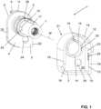
- the wall anchor arrangement comprises a wall anchor 2 and a mounting element 3 that can be connected to the wall anchor 2.
- the mounting element 3 can, as explained below, be connected to the wall anchor 2 in various ways. This allows the mounting element 3 to have different functions.
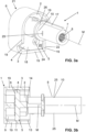
- the mounting element 3 serves as a screwing aid for the wall anchor 2, which can be screwed into a mounting profile. This first mode of operation is described in the Figures 2a, 2b and 6a, 6b shown.
- the mounting element 3 serves as a support element of the wall anchor 2 on a building wall when the wall anchor 2 is mounted without a mounting profile.
- the wall anchor 2 comprises an anchor plate 4 with a front surface 5 and a rear surface 6, a fastening section 7 protruding from the front surface 5 of the anchor plate 4 and a locking section 9 protruding from the rear surface 6.
- the fastening section 7 extends along a central axis M and has a threaded structure 8 for receiving an anchor screw.
- the anchor screw can be used, for example, to connect the mounting frame to the wall anchor.
- the locking section 9 protrudes from the rear surface 6 and is used to lock the wall anchor 2 into a mounting rail.
- the wall anchor 2 has a first wall anchor-side bearing section 10 and a second wall anchor-side bearing section 11.
- the mounting element 3 has a first mounting element-side bearing section 12 and a second mounting element-side bearing section 13.
- the mounting element 3 can be connected to the wall anchor 2 either via the first bearing sections 10, 12 or via the second bearing sections 11, 13.
- connection between the mounting element 3 and the wall anchor 2 is shown via the two first bearing sections 10, 12.
- a rotary movement can be transferred to the wall anchor 2, so that the locking section 9 can be connected to a mounting profile via the rotary movement.
- the two first bearing sections 10, 12 are connected to one another in a rotationally fixed manner.
- the installer can Mounting profile, grasp the wall anchor 2 on the mounting element 3 and then insert it into the mounting profile using a rotating movement.
- connection between the mounting element 3 and the wall anchor 2 is shown via the two second bearing sections 11, 13.
- the mounting element 3 covers the latching section 9 and provides a support for the wall anchor 2 on a building wall. This ensures that the wall anchor 2 rests on the building wall with the mounting element 3 and not with the latching section 9 when mounted without a mounting profile.
- the mounting element 3 has a bearing opening 14, which provides the first mounting element-side bearing section 12.
- the first wall anchor-side bearing section 10 is located on the outside of the fastening section 7. When the two first bearing sections 10, 12 are connected to one another, the fastening section 7 protrudes through the bearing opening 14 and protrudes from the bearing opening 14 opposite the anchor plate 4, so that the fastening section 7 remains accessible.
- the shape and size of the bearing opening is complementary or suitable for the shape and size of the fastening section 7.
- the storage opening 14 is provided by a wall structure 15.
- the wall structure 15 protrudes from a bottom wall 18.
- the storage opening 14 extends through the wall structure 15 and the bottom wall 18.
- the first mounting element-side bearing section 12 has a comb 17 and the first wall anchor-side bearing section 10 has a groove 16, wherein the comb 17 engages in the groove 16.
- the first embodiment one groove 16 and one comb 17 are arranged.
- two grooves 16 and two combs 17 are arranged.
- the grooves 16 and the combs 17 each have different widths.
- the mounting element 3 also has a side wall 19 which protrudes from the bottom wall 18.
- the bottom wall 18 and the side wall 19 define a spatial area 20 in which the locking section 9 comes to lie when the mounting element 3 is attached to the Wall anchor 2 is mounted. It is placed on the Figures 3a, 3b and 7, 7b
- the floor wall 18 has a flat support surface 21 opposite the room area 20, with which the mounting element 3 can be brought into contact with a building structure. This provides a good support for the wall anchor arrangement.
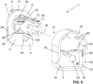
- the anchor plate 4 has an outer contour 22 which is at least partially complementary to the inner contour 23 of the spatial area 20. Complementary is to be understood in such a way that the outer contour is at least partially designed to match the inner contour, such that the anchor plate 4 can be inserted into the spatial area.
- the outer contour 22 comprises several corner areas, one of the corner areas being designed as a corner and the other corner areas each being rounded with a curve.
- the anchor plate 4 and the base wall 18 each have a congruently arranged through opening 24, which, when the mounting element 3 is mounted on the wall anchor 2 via the second bearing sections 11, 13, are congruently located.
- the through openings 24 are in the Figures 1 and 5 clearly visible. A screw can be passed through the through hole 24 to fix the wall anchor 2 to the building wall.
- the Figures 4 and 8 show a planking plate 27 in addition to the wall anchor arrangement 1.
- the mounting element 3 has at least one stop surface 26, which provides a stop for the planking plate 27.
- the entire outside of the mounting element 3 serves as a stop surface 26.
- the distance of the stop surfaces 26 to the center of the bearing opening 14 is variable, so that different distances can be set.
- the first bearing sections 10, 12 and the second bearing sections 11, 13 are arranged in the embodiment shown such that the distance between the center axis and the at least one stop surface, seen transversely to the center axis M, in the connection via the first bearing sections 10, 12 is the same as the connection via the second bearing sections 11, 13.
- the wall anchor 2 according to the second embodiment further comprises a profile section 28.
- the profile section 28 protrudes from the fastening section 7 on both sides and is formed onto the fastening section 7.
- the bearing opening 14 has a shape which is designed to match the profile section 28. In the area of the bearing opening 14 and the locking structures 25 are arranged on the profile section 28.
- the wall anchor 2 is made of a metallic material and the mounting element 3 is made of a plastic.
- the thread structure 8 can be an internal thread, as in the Figures 1 to 4 shown, or a threaded segment which is part of an insertion element 28 which is slidably mounted on the fastening section 7.
Landscapes
- Engineering & Computer Science (AREA)
- General Engineering & Computer Science (AREA)
- Mechanical Engineering (AREA)
- Joining Of Building Structures In Genera (AREA)
Abstract
Description
- Die vorliegende Erfindung betrifft eine Wandankeranordnung, insbesondere für die Befestigung eines Montagerahmens einer Sanitärartikelanordnung, nach Anspruch 1 und eine Anordnung nach Anspruch 15.
- Aus dem Stand der Technik sind Montagerahmen zur Lagerung von Sanitärartikel bekannt geworden. Derartige Montagerahmen werden typischerweise mit einer Ankerschraube und einem Wandanker zu einer festen Tragstruktur, wie zu einer Gebäudewand, befestigt.
- Die
DE 299 16 234 U1 offenbart eine Schnellbefestigung, bei welcher eine C-Schiene an einer Wand befestigt wird. Ein Winkelträger wird dabei mit der C-Schiene über eine Schraubverbindung verbunden. Die Schraubverbindung muss mit einem Werkzeug fest angezogen werden. - Der vorliegenden Erfindung liegt eine Aufgabe zugrunde eine Wandankeranordnung anzugeben, welche in unterschiedlichen Montagekonfigurationen eingesetzt werden kann.
- Diese und andere Aufgaben löst der Gegenstand nach Anspruch 1. Demgemäss umfasst eine Wandankeranordnung, insbesondere für die Befestigung eines Montagerahmens einer Sanitärartikelanordnung, einen Wandanker und ein mit dem Wandanker verbindbares Montageelement. Das Montageelement kann vor der Montage des Wandankers mit dem Wandanker verbunden werden.
- Der Wandanker umfasst eine Ankerplatte mit einer Frontfläche und einer Rückfläche, einen von der Frontfläche der Ankerplatte abstehenden Befestigungsabschnitt, welcher sich entlang einer Mittelachse erstreckt, und welcher eine Gewindestruktur zur Aufnahme einer Ankerschraube aufweist, und einen von der Rückfläche abstehenden Einrastabschnitt. Weiterhin weist der Wandanker einen ersten wandankerseitigen Lagerabschnitt und einen zweiten wandankerseitigen Lagerabschnitt auf. Das Montageelement umfasst einen ersten montageelementseitigen Lagerabschnitt und einen zweiten montageelementseitigen Lagerabschnitt. Das Montagelement ist entweder über die ersten Lagerabschnitte oder über die zweiten Lagerabschnitt mit dem Wandanker verbindbar. Je nach Art der Verbindung liegt das Montageelement an unterschiedlichen Positionen zum Wandanker. Bei bereitgestellter Verbindung zwischen dem Montageelement und dem Wandanker über die beiden ersten Lagerabschnitte ist eine Drehbewegung auf den Wandanker übertragbar, so dass der Einrastabschnitt über die Drehbewegung mit einem Montageprofil verbindbar ist. Bei bereitgestellter Verbindung zwischen dem Montageelement und dem Wandanker über die beiden zweiten Lagerabschnitte überdeckt das Montageelement den Einrastabschnitt und stellt eine Auflage für den Wandanker an einer Gebäudewand bereit.
- Das Montageelement kann für verschiedene Montagearten des Wandankers unterschiedliche Funktionen aufweisen. Wird der Wandanker mit seinem Einrastabschnitt mit einem Montageprofil verbunden, so dient das Montageelement als Hilfsmittel, so dass der Installateur die für die Montage notwendige Drehbewegung aufbringen kann. Wird der Wandanker direkt an eine Gebäudewand montiert, so dient das Montageelement als Auflageelement an die Gebäudewand. Durch die Überdeckung des Einrastabschnitts steht der Wandanker nicht mit dem Einrastabschnitt auf der Gebäudewand auf.
- Vorzugsweise weist das Montageelement eine Lageröffnung auf, welche den ersten montageelementseitigen Lagerabschnitt bereitstellt. Weiter liegt der erste wandankerseitige Lagerabschnitt vorzugsweise aussenseitig am Befestigungsabschnitt.
- Der Befestigungsabschnitt ragt dabei durch die Lageröffnung hindurch und ragt gegenüber der Ankerplatte aus der Lageröffnung hinaus, so dass der Befestigungsabschnitt zugänglich bleibt. Die Form und Grösse der Lageröffnung ist komplementär bzw. passend zur Form und Grösse des Befestigungsabschnitts ausgebildet.
- Vorzugsweise wird die Lageröffnung durch eine Wandstruktur bereitgestellt wird. Die Wandstruktur weist vorzugsweise eine Länge auf, welche eine gewisse Führung für den Befestigungsabschnitt bereitstellt. Besonders bevorzugt entspricht die Länge mindestens dem Aussendurchmesser des Befestigungsabschnitts.
- Vorzugsweise steht die Wandstruktur von der unten genannten Bodenwand ab. Die Öffnung erstreckt sich dabei durch die Wandstruktur und die Bodenwand hindurch.
- In einer bevorzugten Variante weist der erste montageelementseitige Lagerabschnitt eine Nut auf und der erste wandankerseitige Lagerabschnitt weist einen Kamm auf. Der Kamm greift in die Nute ein. In einer anderen bevorzugten Variante weist der erste montageelementseitige Lagerabschnitt einen Kamm auf und der erste wandankerseitige Lagerabschnitt weist eine Nut auf. Bei beiden Variante greift der Kamm in die Nute ein und hierdurch kann eine drehfeste Verbindung bereitgestellt werden. Es können mehrere Nuten und mehrere Kämme vorgesehen sein.
- Vorzugsweise weist das Montageelement eine Bodenwand auf, von welcher eine Seitenwand absteht, wobei die Bodenwand und die Seitenwand einen Raumbereich definieren, in welchen der Einrastabschnitt zu liegen kommt, wenn das Montageelement über die zweiten Lagerabschnitte am Wandanker gelagert ist.
- Vorzugsweise weist die Bodenwand gegenüberliegend zum Raumbereich eine ebene Auflagefläche auf, mit welcher das Montageelement in Kontakt mit einer Gebäudestruktur bringbar ist.
- Im montierten Zustand verläuft die Auflagefläche vorzugsweise rechtwinklig zur Mittelachse vom Befestigungsabschnitt.
- Vorzugsweise weist die Ankerplatte eine Aussenkontur auf, welche mindestens teilweise komplementär zur Innenkontur des Raumbereichs ausgebildet ist.
- Komplementär ist so zu verstehen, dass die Aussenkontur mindestens teilweise passend zur Innenkontur ausgebildet ist, derart, dass die Ankerplatte in den Raumbereich eingelegt werden kann.
- Wenn das Montageelement über die zweiten Lagerabschnitte am Wanderanker gelagert ist, liegt der Einrastabschnitt vorzugsweise innenseitig zum Raumbereich auf der Bodenwand auf.
- Vorzugsweise weisen die Ankerplatte und die Bodenwand jeweils eine deckungsgleich zueinander angeordnete Durchgangsöffnung auf, welche, wenn das Montageelement über die zweiten Lagerabschnitte am Wandanker gelagert ist, deckungsgleich zueinander liegen. Durch die Durchgangsöffnungen kann eine Schraube zur Befestigung der Wandankeranordnung an einer Gebäudewand hindurchgeführt werden.
- Vorzugsweise verfügen die ersten Lagerabschnitte und/oder die zweiten Lagerabschnitte über Raststrukturen verfügen, derart, dass im montierten Zustand über die jeweiligen Lagerabschnitte eine Rastverbindung zwischen dem Wandanker und dem Montageelement bereitstellbar ist. Die Raststrukturen werden vorzugsweise durch Rastnasen und Rastkanten, an welchen die Rastnasen einrasten, bereitgestellt.
- Vorzugsweise weist das Montageelement mindestens eine Anschlagsfläche auf, welche einen Anschlag für eine Beplankungsplatte bereitstellt. Die Anschlagsfläche verläuft bevorzugt parallel zur Mittelachse des Befestigungsabschnitts.
- Vorzugsweise sind die ersten Lagerabschnitte und die zweiten Lagerabschnitte derart angeordnet, dass der Abstand zwischen der Mittelachse und der mindestens einen Anschlagsfläche quer zur Mittelachse gesehen, bei der Verbindung über die ersten Lagerabschnitte gleich zu der Verbindung über die zweiten Lagerabschnitte ist.
- Vorzugsweise ist dem Befestigungsabschnitt ein Profilabschnitt angeformt, der sich quer zum Befestigungsabschnitt vom Befestigungsabschnitt erstreckt und von diesem absteht. Der Profilabschnitt kommt in die Lageröffnung am Montageelement zu liegen. Dabei haben die Projektion des Profilabschnitts in Richtung der Mittelachse und die Lageröffnung die gleiche Form. Der Profilabschnitt wirkt dabei als Verdrehsicherung. Ebenfalls können im Bereich der Lageröffnung und am Profilabschnitt die oben genannten Raststrukturen angeordnet sein.
- Vorzugsweise weist der Befestigungsabschnitt eine Anschlagsfläche auf, an der das Montageelement anschlägt, wenn das Montageelement über die ersten Lagerabschnitte am Wandanker gelagert ist.
- Anordnung umfassend mindestens eine Wandankeranordnung nach obiger Beschreibung sowie ein Montageprofil und/oder eine Gebäudewand, wobei
- bei einer Verbindung des Wandankers mit dem Montageprofil das Montageelement über die ersten Lagerabschnitte am Wandanker gelagert ist und
- wobei bei einer Verbindung des Wandankers mit der Gebäudewand das Montageelement über die zweiten Lagerabschnitte am Wandanker gelagert ist.
- Weitere Ausführungsformen sind in den abhängigen Ansprüchen angegeben.
- Bevorzugte Ausführungsformen der Erfindung werden im Folgenden anhand der Zeichnungen beschrieben, die lediglich zur Erläuterung dienen und nicht einschränkend auszulegen sind. In den Zeichnungen zeigen:
- Fig. 1
- eine perspektivische Explosionsansicht einer Wandankeranordnung nach einer ersten Ausführungsform;
- Fig. 2a
- die Wandankeranordnung nach
Figur 1 in einer ersten Konfiguration; - Fig. 2b
- eine Schnittdarstellung der
Figur 2a ; - Fig. 3a
- die Wandankeranordnung nach
Figur 1 in einer ersten Konfiguration; - Fig. 3b
- eine Schnittdarstellung der
Figur 3a ; - Fig. 4
- die Wandankeranordnung nach den
Figuren 1 bis 3b mit einer Beplankungsplatte; - Fig. 5
- eine perspektivische Explosionsansicht einer Wandankeranordnung nach einer zweiten Ausführungsform;
- Fig. 6a
- die Wandankeranordnung nach
Figur 5 in einer ersten Konfiguration; - Fig. 6b
- eine Schnittdarstellung der
Figur 6a ; - Fig. 7a
- die Wandankeranordnung nach
Figur 1 in einer ersten Konfiguration; - Fig. 7b
- eine Schnittdarstellung der
Figur 6a ; und - Fig. 8
- die Wandankeranordnung nach den
Figuren 5 bis 7b mit einer Beplankungsplatte. - In den Figuren werden zwei Ausführungsformen einer erfindungsgemässen Wandankeranordnung gezeigt. Gleiche Teile sind mit gleichen Bezugszeichen versehen.
- Die Wandankeranordnung gemäss beiden Ausführungsformen dient vorzugsweise der Befestigung eines Montagerahmens zur einer Gebäudestruktur bzw. zu einer Gebäudewand. Am Montagerahmen ist mindestens ein Sanitärartikel, wie beispielsweise ein Spülkasten, eine Toilettenschüssel, ein Urinal, ein Waschtsich, etc. gelagert. Die Wandankeranordnung umfasst einen Wandanker 2 und ein mit dem Wandanker 2 verbindbares Montageelement 3. Das Montageelement 3 kann, wie unten erläutert wird, auf verschiedene Weise mit dem Wandanker 2 verbunden werden. Dadurch kann das Montageelement 3 unterschiedliche Funktionen aufweisen. Gemäss einer ersten Funktionsweise dient das Montageelement 3 als Eindrehhilfe für den Wandanker 2, welche in eine Montageprofil eingedreht werden kann. Diese erste Funktionsweise wird in den
Figuren 2a, 2b und6a, 6b gezeigt. Gemäss einer zweiten Funktionsweise dient das Montageelement 3 als Abstützelement des Wandankers 2 an einer Gebäudewand, wenn der Wandanker 2 ohne Montageprofil montiert wird. - Der Wandanker 2 umfasst eine Ankerplatte 4 mit einer Frontfläche 5 und einer Rückfläche 6, einen von der Frontfläche 5 der Ankerplatte 4 abstehenden Befestigungsabschnitt 7 und einen von der Rückfläche 6 abstehenden Einrastabschnitt 9. Der Befestigungsabschnitt 7 erstreckt sich entlang einer Mittelachse M und weist eine Gewindestruktur 8 zur Aufnahme einer Ankerschraube auf. Mit der Ankerschraube kann beispielsweise der Montagerahmen mit dem Wandanker verbunden werden. Der Einrastabschnitt 9 steht von der Rückfläche 6 und dient dem Einrasten des Wandankers 2 in eine Montageschiene.
- Für die Lagerung des Montageelements 3 weist der Wandanker 2 einen ersten wandankerseitigen Lagerabschnitt 10 und einen zweiten wandankerseitigen Lagerabschnitt 11 auf. Das Montageelement 3 weist einen ersten montageelementseitigen Lagerabschnitt 12 und einen zweiten montageelementseitigen Lagerabschnitt 13 auf. Das Montagelement 3 ist entweder über die ersten Lagerabschnitte 10, 12 oder über die zweiten Lagerabschnitte 11, 13 mit dem Wandanker 2 verbindbar.
- In den
Figuren 2a, 2b und6a, 6b wird die Verbindung zwischen dem Montageelement 3 und dem Wandanker 2 über die beiden ersten Lagerabschnitte 10, 12 gezeigt. Bei bereitgestellter Verbindung zwischen dem Montageelement 3 und dem Wandanker 2 über die beiden ersten Lagerabschnitte 10, 12 ist eine Drehbewegung auf den Wandanker 2 übertragbar, so dass der Einrastabschnitt 9 über die Drehbewegung mit einem Montageprofil verbindbar ist. Die beiden ersten Lagerabschnitt 10, 12 stehen drehfest miteinander in Verbindung. Der Installateur kann bei der Montage des Wandankers 2 in ein Montageprofil, den Wandanker 2 am Montageelement 3 ergreifen und diesen dann über eine Drehbewegung in das Montageprofil einsetzen. - In den
Figuren 3a, 3b und7a, 7b wird die Verbindung zwischen dem Montageelement 3 und dem Wandanker 2 über die beiden zweiten Lagerabschnitte 11, 13 gezeigt Bei bereitgestellter Verbindung zwischen dem Montageelement 3 und dem Wandanker 2 über die beiden zweiten Lagerabschnitte 11, 13 das Montageelement 3 den Einrastabschnitt 9 überdeckt und eine Auflage für den Wandanker 2 an einer Gebäudewand bereitstellt. Hierdurch wird sichergestellt, dass der Wandanker 2 bei der Montage ohne Montageprofil mit dem Montageelement 3 und nicht mit dem Einrastabschnitt 9 auf der Gebäudewand aufsteht. - Das Montageelement 3 weist eine Lageröffnung 14 auf, welche den ersten montageelementseitigen Lagerabschnitt 12 bereitstellt. Der erste wandankerseitige Lagerabschnitt 10 liegt aussenseitig am Befestigungsabschnitt 7. Wenn die beiden ersten Lagerabschnitt 10, 12 miteinander in Verbindung stehen, ragt der Befestigungsabschnitt 7 durch die Lageröffnung 14 hindurch und ragt gegenüber der Ankerplatte 4 aus der Lageröffnung 14 hinaus, so dass der Befestigungsabschnitt 7 zugänglich bleibt. Die Form und Grösse der Lageröffnung ist komplementär bzw. passend zur Form und Grösse des Befestigungsabschnitts 7 ausgebildet.
- Die Lageröffnung 14 wird durch eine Wandstruktur 15 bereitgestellt. Die Wandstruktur 15 steht von einer Bodenwand 18 ab. Die Lageröffnung 14 erstreckt sich dabei durch die Wandstruktur 15 und die Bodenwand 18 hindurch.
- Für die drehfeste Verbindung weist der erste montageelementseitige Lagerabschnitt 12 einen Kamm 17 auf und der erste wandankerseitige Lagerabschnitt 10 weist eine Nut 16 auf, wobei der Kamm 17 in die Nute 16 eingreift. In der ersten Ausführungsform ist eine Nute 16 und ein Kamm 17 angeordnet. In der zweiten Ausführungsform sind zwei Nuten 16 und zwei Kämme 17 angeordnet. Die Nuten 16 bzw. die Kämme 17 haben jeweils unterschiedliche Breiten.
- Nebst der oben genannten Bodenwand weist das Montageelement 3 weiterhin eine Seitenwand 19 auf, welche von der Bodenwand 18 absteht. Die Bodenwand 18 und die Seitenwand 19 definieren einen Raumbereich 20, in welchen der Einrastabschnitt 9 zu liegen kommt, wenn das Montageelement 3 über die zweiten Lagerabschnitte 11, 13 am Wandanker 2 gelagert ist. Es wird auf die
Figuren 3a, 3b und7, 7b verwiesen. Die Bodenwand 18 weist gegenüberliegend zum Raumbereich 20 eine ebene Auflagefläche 21 auf, mit welcher das Montageelement 3 in Kontakt mit einer Gebäudestruktur bringbar ist. Hierdurch wird eine gute Auflage der Wandankeranordnung bereitgestellt. - Wie von den
Figuren 1 und5 ersichtlich ist, weist die Ankerplatte 4 eine Aussenkontur 22 auf, welche mindestens teilweise komplementär zur Innenkontur 23 des Raumbereichs 20 ausgebildet ist. Komplementär ist so zu verstehen, dass die Aussenkontur mindestens teilweise passend zur Innenkontur ausgebildet ist, derart, dass die Ankerplatte 4 in den Raumbereich eingelegt werden kann. Die Aussenkontur 22 umfasst dabei mehrere Eckbereiche, wobei einer der Eckbereiche als Ecke ausgebildet ist und die anderen Eckbereiche jeweils mit einer Rundung gerundet ausgebildet sind. - Die Ankerplatte 4 und die Bodenwand 18 weisen jeweils eine deckungsgleich zueinander angeordnete Durchgangsöffnung 24 auf, welche, wenn das Montageelement 3 über die zweiten Lagerabschnitte 11, 13 am Wandanker 2 gelagert ist, deckungsgleich zueinander liegen. Die Durchgangsöffnungen 24 sind in den
Figuren 1 und5 gut erkennbar. Durch die Durchgangsöffnung 24 kann eine Schraube hindurchgeführt werden, um den Wandanker 2 zur Gebäudewand zu fixieren. - Die
Figuren 4 und8 zeigen zusätzlich zu der Wandankeranordnung 1 eine Beplankungsplatte 27. Das Montageelement 3 weist mindestens eine Anschlagsfläche 26 auf, welche einen Anschlag für die Beplankungsplatte 27 bereitstellt. In der gezeigten Ausführungsform dient die gesamte Aussenseite des Montageelements 3 als Anschlagsfläche 26. Der Abstand der Anschlagsflächen 26 zum Zentrum der Lageröffnung 14 ist dabei variabel ausgebildet, so dass unterschiedliche Abstände einstellbar sind. Die ersten Lagerabschnitte 10, 12 und die zweiten Lagerabschnitte 11, 13 sind in der gezeigten Ausführungsform derart angeordnet, dass der Abstand zwischen der Mittelachse und der mindestens einen Anschlagsfläche quer zur Mittelachse M gesehen, bei der Verbindung über die ersten Lagerabschnitte 10, 12 gleich zu der Verbindung über die zweiten Lagerabschnitte 11, 13 ist. - Der Wandanker 2 gemäss der zweiten Ausführungsform weist weiterhin einen Profilabschnitt 28 auf. Der Profilabschnitt 28 steht beidseitig vom Befestigungsabschnitt 7 ab und ist dem Befestigungsabschnitt 7 angeformt. Die Lageröffnung 14 weist eine Form auf, welche passend zum Profilabschnitt 28 ausgebildet ist. Im Bereich der Lageröffnung 14 und am Profilabschnitt 28 sind die Raststrukturen 25 angeordnet.
- Vorzugsweise ist der Wandanker 2 aus einem metallischen Werkstoff und das Montageelement 3 ist aus einem Kunststoff.
- Die Gewindestruktur 8 kann ein Innengewinde sein, so wie in den
Figuren 1 bis 4 dargestellt, oder ein Gewindesegment sein, das Teil eines Einschiebeelementes 28 ist, welches verschiebbar am Befestigungsabschnitt 7 gelagert ist. -
1 Wandankeranordnung 25 Raststrukturen 2 Wandanker 26 Anschlagsfläche 3 Montageelement 27 Beplankungsplatte 4 Ankerplatte 28 Profilabschnitt 5 Fronfläche M Mittelachse 6 Rückfläche 7 Befestigungsabschnitt 8 Gewindestruktur 9 Einrastabschnitt 10 erster wandankerseitiger Lagerabschnitt 11 zweiter wandankerseitiger Lagerabschnitt 12 erster montageelementseitiger Lagerabschnitt 13 zweiter montageelementseitiger Lagerabschnitt 14 Lageröffnung 15 Wandstruktur 16 Nut 17 Kamm 18 Bodenwand 19 Seitenwand 20 Raumbereich 21 Auflagefläche 22 Aussenkontur 23 Innenkontur 24 Durchgangsöffnung
Claims (15)
- Wandankeranordnung (1), insbesondere für die Befestigung eines Montagerahmens einer Sanitärartikelanordnung, umfassend einen Wandanker (2) und ein mit dem Wandanker (2) verbindbares Montageelement (3),wobei der Wandanker (2) eine Ankerplatte (4) mit einer Frontfläche (5) und einer Rückfläche (6), einen von der Frontfläche (5) der Ankerplatte (4) abstehenden Befestigungsabschnitt (7), welcher sich entlang einer Mittelachse (M) erstreckt, und welcher eine Gewindestruktur (8) zur Aufnahme einer Ankerschraube aufweist, und einen von der Rückfläche (6) abstehenden Einrastabschnitt (9) umfasst,wobei der Wandanker (2) weiterhin einen ersten wandankerseitigen Lagerabschnitt (10) und einen zweiten wandankerseitigen Lagerabschnitt (11) aufweist,wobei das Montageelement (3) einen ersten montageelementseitigen Lagerabschnitt (12) und einen zweiten montageelementseitigen Lagerabschnitt (13) umfasst,wobei das Montagelement (3) entweder über die ersten Lagerabschnitte (10, 12) oder über die zweiten Lagerabschnitte (11, 13) mit dem Wandanker (2) verbindbar ist,wobei bei bereitgestellter Verbindung zwischen dem Montageelement (3) und dem Wandanker (2) über die beiden ersten Lagerabschnitte (10, 12) eine Drehbewegung auf den Wandanker (2) übertragbar ist, so dass der Einrastabschnitt (9) über die Drehbewegung mit einem Montageprofil verbindbar ist, undwobei bei bereitgestellter Verbindung zwischen dem Montageelement (3) und dem Wandanker (2) über die beiden zweiten Lagerabschnitte (11, 13) das Montageelement den Einrastabschnitt (9) überdeckt und eine Auflage für den Wandanker (2) an einer Gebäudewand bereitstellt.
- Wandankeranordnung (1) nach Anspruch 1, dadurch gekennzeichnet, dass das Montageelement (3) eine Lageröffnung (14) aufweist, welche den ersten montageelementseitigen Lagerabschnitt (12) bereitstellt, und dass der erste wandankerseitige Lagerabschnitt (10) aussenseitig am Befestigungsabschnitt (7) liegt.
- Wandankeranordnung (1) nach Anspruch 2, dadurch gekennzeichnet, dass die Lageröffnung (14) durch eine Wandstruktur (15) bereitgestellt wird.
- Wandankeranordnung (1) nach Anspruch 2 oder 3, dadurch gekennzeichnet, dass der erste montageelementseitige Lagerabschnitt (12) eine Nut (16) aufweist und dass der erste wandankerseitige Lagerabschnitt (10) einen Kamm (17) aufweist, wobei der Kamm (16) in die Nute (16) eingreift; oder dass der erste montageelementseitige Lagerabschnitt (12) einen Kamm (17) aufweist und dass der erste wandankerseitige Lagerabschnitt (10) eine Nut (16) aufweist, wobei der Kamm (17) in die Nute (16) eingreift.
- Wandankeranordnung (1) nach einem der vorhergehenden Ansprüche, dadurch gekennzeichnet, dass das Montageelement (3) eine Bodenwand (18) aufweist, von welcher eine Seitenwand (19) absteht, wobei die Bodenwand (18) und die Seitenwand (19) einen Raumbereich (20) definieren, in welchen der Einrastabschnitt (9) zu liegen kommt, wenn das Montageelement (3) über die zweiten Lagerabschnitte (11, 13) am Wandanker (2) gelagert ist.
- Wandankeranordnung (1) nach Anspruch 5, dadurch gekennzeichnet, dass die Bodenwand (18) gegenüberliegend zum Raumbereich (20) eine ebene Auflagefläche (21) aufweist, mit welcher das Montageelement (3) in Kontakt mit einer Gebäudestruktur bringbar ist.
- Wandankeranordnung (1) nach einem der Ansprüche 5 oder 6, dadurch gekennzeichnet, dass die Ankerplatte (4) eine Aussenkontur (22) aufweist, welche mindestens teilweise komplementär zur Innenkontur (23) des Raumbereichs (20) ausgebildet ist.
- Wandankeranordnung (1) nach einem der Ansprüche 4 bis 7, dadurch gekennzeichnet, dass, wenn das Montageelement (3) über die zweiten Lagerabschnitte (11, 13) am Wanderanker (2) gelagert ist, der Einrastabschnitt (9) innenseitig zum Raumbereich (20) auf der Bodenwand (18) aufliegt.
- Wandankeranordnung (1) nach einem der vorhergehenden Ansprüche 5 bis 8, dadurch gekennzeichnet, dass die Ankerplatte (4) und die Bodenwand (18) jeweils eine deckungsgleich zueinander angeordnete Durchgangsöffnung (24) aufweisen, welche, wenn das Montageelement (3) über die zweiten Lagerabschnitte (11, 13) am Wandanker (2) gelagert ist, deckungsgleich zueinander liegen.
- Wandankeranordnung (1) nach einem der vorhergehenden Ansprüche, dadurch gekennzeichnet, dass die ersten Lagerabschnitte (10, 12) und/oder die zweiten Lagerabschnitte (11, 13) über Raststrukturen (25) verfügen, derart, dass im montierten Zustand über die jeweiligen Lagerabschnitte (10, 11, 12, 13) eine Rastverbindung zwischen dem Wandanker (2) und dem Montageelement (3) bereitstellbar ist.
- Wandankeranordnung (1) nach einem der vorhergehenden Ansprüche, dadurch gekennzeichnet, dass das Montageelement (3) mindestens eine Anschlagsfläche (26) aufweist, welche einen Anschlag für eine Beplankungsplatte (27) bereitstellt.
- Wandankeranordnung (1) nach einem der vorhergehenden Ansprüche, dadurch gekennzeichnet, dass die ersten Lagerabschnitte (10, 12) und die zweiten Lagerabschnitte (11, 13) derart angeordnet sind, dass der Abstand zwischen der Mittelachse und der mindestens einen Anschlagsfläche quer zur Mittelachse (M) gesehen, bei der Verbindung über die ersten Lagerabschnitte (10, 12) gleich zu der Verbindung über die zweiten Lagerabschnitte (11, 13) ist.
- Wandankeranordnung (1) nach einem der vorhergehenden Ansprüche, dadurch gekennzeichnet, dass dem Befestigungsabschnitt (7) ein Profilabschnitt (28) angeformt ist, der sich quer zum Befestigungsabschnitt (7) vom Befestigungsabschnitt (7) erstreckt und von diesem absteht.
- Wandankeranordnung (1) nach einem der vorhergehenden Ansprüche, dadurch gekennzeichnet, dass der Befestigungsabschnitt (7) eine Anschlagsfläche aufweist, an der das Montageelement (3) anschlägt, wenn das Montageelement (3) über die ersten Lagerabschnitte (10, 12) am Wandanker (2) gelagert ist.
- Anordnung umfassend mindestens eine Wandankeranordnung nach einem der vorhergehenden Ansprüche sowie ein Montageprofil und/oder eine Gebäudewand, wobei bei einer Verbindung des Wandankers (2) mit dem Montageprofil das Montageelement (3) über die ersten Lagerabschnitte (10, 12) am Wandanker (2) gelagert ist und wobei bei einer Verbindung des Wandankers (2) mit der Gebäudewand das Montageelement (3) über die zweiten Lagerabschnitte (11, 13) am Wandanker (2) gelagert ist.
Priority Applications (1)
| Application Number | Priority Date | Filing Date | Title |
|---|---|---|---|
| EP23177707.9A EP4474658B1 (de) | 2023-06-06 | 2023-06-06 | Wandankeranordnung |
Applications Claiming Priority (1)
| Application Number | Priority Date | Filing Date | Title |
|---|---|---|---|
| EP23177707.9A EP4474658B1 (de) | 2023-06-06 | 2023-06-06 | Wandankeranordnung |
Publications (2)
| Publication Number | Publication Date |
|---|---|
| EP4474658A1 true EP4474658A1 (de) | 2024-12-11 |
| EP4474658B1 EP4474658B1 (de) | 2026-01-21 |
Family
ID=86732158
Family Applications (1)
| Application Number | Title | Priority Date | Filing Date |
|---|---|---|---|
| EP23177707.9A Active EP4474658B1 (de) | 2023-06-06 | 2023-06-06 | Wandankeranordnung |
Country Status (1)
| Country | Link |
|---|---|
| EP (1) | EP4474658B1 (de) |
Citations (3)
| Publication number | Priority date | Publication date | Assignee | Title |
|---|---|---|---|---|
| DE29916234U1 (de) | 1999-09-15 | 1999-12-09 | Ferroplast GmbH, 40789 Monheim | Schnellbefestigung |
| EP3926112A1 (de) * | 2020-06-17 | 2021-12-22 | Alca plast, s.r.o. | Befestigungshalterung zur verankerung von halterahmen von sanitäreinrichtungen an mauerwerk |
| EP4039897A1 (de) * | 2021-02-04 | 2022-08-10 | Geberit International AG | Wandhalterung |
-
2023
- 2023-06-06 EP EP23177707.9A patent/EP4474658B1/de active Active
Patent Citations (3)
| Publication number | Priority date | Publication date | Assignee | Title |
|---|---|---|---|---|
| DE29916234U1 (de) | 1999-09-15 | 1999-12-09 | Ferroplast GmbH, 40789 Monheim | Schnellbefestigung |
| EP3926112A1 (de) * | 2020-06-17 | 2021-12-22 | Alca plast, s.r.o. | Befestigungshalterung zur verankerung von halterahmen von sanitäreinrichtungen an mauerwerk |
| EP4039897A1 (de) * | 2021-02-04 | 2022-08-10 | Geberit International AG | Wandhalterung |
Also Published As
| Publication number | Publication date |
|---|---|
| EP4474658B1 (de) | 2026-01-21 |
Similar Documents
| Publication | Publication Date | Title |
|---|---|---|
| EP0761130B1 (de) | Halterungs-Beschlag für Frontblenden von Schubladen | |
| EP3746608B1 (de) | Befestigungssystem zur befestigung eines sanitärartikels | |
| DE3119571C2 (de) | ||
| DE102013105544A1 (de) | Wasserablaufvorrichtung für eine sanitäre Anlage, wie einen bodenebenen Duschplatz | |
| EP2876222B1 (de) | Einheit umfassend eine Befestigungsvorrichtung für ein hängendes WC und ein Halteelement. | |
| DE10310778B4 (de) | Bausatz für Verteilerschränke | |
| EP1439278A2 (de) | Dichtung, insbesondere Auflaufdichtung oder sich selbsttätig absenkende Bodendichtung für Türen mit einstellbarer Befestigung | |
| EP4474658B1 (de) | Wandankeranordnung | |
| DE29508686U1 (de) | Bausatz zum Erstellen von Umkleidekabinen, Trennwänden u.dgl. | |
| EP1640524A2 (de) | Baukasten zum Erstellen einer Halterung insbesondere für Rohrleitungen | |
| EP4230885B1 (de) | Wandanker | |
| EP2425066B1 (de) | Trennwandsystem für den Innenausbau | |
| EP0736660A1 (de) | Türschwelle | |
| EP0959536B1 (de) | Steckdosenleiste | |
| EP3913183B1 (de) | Statikteil für einen rollladenkasten | |
| DE19614942B4 (de) | Profilverbindung für unter Gehrung zusammenstoßende Profile | |
| EP0731226A2 (de) | Vorwandelement für die Sanitärinstallation | |
| EP1038486B1 (de) | Bausatz für Duschabtrennungen | |
| EP4223946B1 (de) | Montagesystem für sanitärartikel | |
| EP3510221B1 (de) | System mit einem beschlagteil und mit einem profil | |
| DE8806453U1 (de) | In eine Öffnung einer Gehäusewand einsetzbarer Schalengriff | |
| EP4001527A1 (de) | Wandhalter, insbesondere für ein sanitärobjekt | |
| WO2021073831A1 (de) | Band zur schwenkbaren verbindung eines flügels mit einem rahmen | |
| EP4399371B1 (de) | Montagevorrichtung für einen sanitärartikel | |
| EP3741274B1 (de) | Befestigungsvorrichtung für toilettenabdeckungen |
Legal Events
| Date | Code | Title | Description |
|---|---|---|---|
| PUAI | Public reference made under article 153(3) epc to a published international application that has entered the european phase |
Free format text: ORIGINAL CODE: 0009012 |
|
| STAA | Information on the status of an ep patent application or granted ep patent |
Free format text: STATUS: THE APPLICATION HAS BEEN PUBLISHED |
|
| AK | Designated contracting states |
Kind code of ref document: A1 Designated state(s): AL AT BE BG CH CY CZ DE DK EE ES FI FR GB GR HR HU IE IS IT LI LT LU LV MC ME MK MT NL NO PL PT RO RS SE SI SK SM TR |
|
| STAA | Information on the status of an ep patent application or granted ep patent |
Free format text: STATUS: REQUEST FOR EXAMINATION WAS MADE |
|
| 17P | Request for examination filed |
Effective date: 20250327 |
|
| GRAP | Despatch of communication of intention to grant a patent |
Free format text: ORIGINAL CODE: EPIDOSNIGR1 |
|
| STAA | Information on the status of an ep patent application or granted ep patent |
Free format text: STATUS: GRANT OF PATENT IS INTENDED |
|
| RIC1 | Information provided on ipc code assigned before grant |
Ipc: F16B 5/06 20060101AFI20250821BHEP Ipc: E03C 1/32 20060101ALN20250821BHEP Ipc: E03D 11/14 20060101ALN20250821BHEP Ipc: F16B 21/07 20060101ALN20250821BHEP Ipc: F16B 21/08 20060101ALN20250821BHEP |
|
| INTG | Intention to grant announced |
Effective date: 20250917 |
|
| P01 | Opt-out of the competence of the unified patent court (upc) registered |
Free format text: CASE NUMBER: UPC_APP_0010377_4474658/2025 Effective date: 20251020 |
|
| GRAS | Grant fee paid |
Free format text: ORIGINAL CODE: EPIDOSNIGR3 |
|
| GRAA | (expected) grant |
Free format text: ORIGINAL CODE: 0009210 |
|
| STAA | Information on the status of an ep patent application or granted ep patent |
Free format text: STATUS: THE PATENT HAS BEEN GRANTED |
|
| AK | Designated contracting states |
Kind code of ref document: B1 Designated state(s): AL AT BE BG CH CY CZ DE DK EE ES FI FR GB GR HR HU IE IS IT LI LT LU LV MC ME MK MT NL NO PL PT RO RS SE SI SK SM TR |
|
| REG | Reference to a national code |
Ref country code: CH Ref legal event code: F10 Free format text: ST27 STATUS EVENT CODE: U-0-0-F10-F00 (AS PROVIDED BY THE NATIONAL OFFICE) Effective date: 20260121 |
|
| REG | Reference to a national code |
Ref country code: DE Ref legal event code: R096 Ref document number: 502023002778 Country of ref document: DE Ref country code: CH Ref legal event code: R17 Free format text: ST27 STATUS EVENT CODE: U-0-0-R10-R17 (AS PROVIDED BY THE NATIONAL OFFICE) Effective date: 20260212 |
|
| REG | Reference to a national code |
Ref country code: IE Ref legal event code: FG4D Free format text: LANGUAGE OF EP DOCUMENT: GERMAN |