EP4473850A2 - Vorrichtung enthaltend einen heizschacht enthaltend ein kapsel enthaltend einen matrix - Google Patents
Vorrichtung enthaltend einen heizschacht enthaltend ein kapsel enthaltend einen matrix Download PDFInfo
- Publication number
- EP4473850A2 EP4473850A2 EP24186044.4A EP24186044A EP4473850A2 EP 4473850 A2 EP4473850 A2 EP 4473850A2 EP 24186044 A EP24186044 A EP 24186044A EP 4473850 A2 EP4473850 A2 EP 4473850A2
- Authority
- EP
- European Patent Office
- Prior art keywords
- capsule
- matrix
- filler material
- example embodiment
- flavorant
- Prior art date
- Legal status (The legal status is an assumption and is not a legal conclusion. Google has not performed a legal analysis and makes no representation as to the accuracy of the status listed.)
- Pending
Links
Images



Classifications
-
- A—HUMAN NECESSITIES
- A24—TOBACCO; CIGARS; CIGARETTES; SIMULATED SMOKING DEVICES; SMOKERS' REQUISITES
- A24B—MANUFACTURE OR PREPARATION OF TOBACCO FOR SMOKING OR CHEWING; TOBACCO; SNUFF
- A24B15/00—Chemical features or treatment of tobacco; Tobacco substitutes, e.g. in liquid form
- A24B15/10—Chemical features of tobacco products or tobacco substitutes
- A24B15/16—Chemical features of tobacco products or tobacco substitutes of tobacco substitutes
- A24B15/165—Chemical features of tobacco products or tobacco substitutes of tobacco substitutes comprising as heat source a carbon fuel or an oxidized or thermally degraded carbonaceous fuel, e.g. carbohydrates, cellulosic material
-
- A—HUMAN NECESSITIES
- A24—TOBACCO; CIGARS; CIGARETTES; SIMULATED SMOKING DEVICES; SMOKERS' REQUISITES
- A24B—MANUFACTURE OR PREPARATION OF TOBACCO FOR SMOKING OR CHEWING; TOBACCO; SNUFF
- A24B15/00—Chemical features or treatment of tobacco; Tobacco substitutes, e.g. in liquid form
- A24B15/10—Chemical features of tobacco products or tobacco substitutes
- A24B15/16—Chemical features of tobacco products or tobacco substitutes of tobacco substitutes
- A24B15/167—Chemical features of tobacco products or tobacco substitutes of tobacco substitutes in liquid or vaporisable form, e.g. liquid compositions for electronic cigarettes
-
- A—HUMAN NECESSITIES
- A24—TOBACCO; CIGARS; CIGARETTES; SIMULATED SMOKING DEVICES; SMOKERS' REQUISITES
- A24B—MANUFACTURE OR PREPARATION OF TOBACCO FOR SMOKING OR CHEWING; TOBACCO; SNUFF
- A24B15/00—Chemical features or treatment of tobacco; Tobacco substitutes, e.g. in liquid form
- A24B15/18—Treatment of tobacco products or tobacco substitutes
- A24B15/28—Treatment of tobacco products or tobacco substitutes by chemical substances
- A24B15/285—Treatment of tobacco products or tobacco substitutes by chemical substances characterised by structural features, e.g. particle shape or size
-
- A—HUMAN NECESSITIES
- A24—TOBACCO; CIGARS; CIGARETTES; SIMULATED SMOKING DEVICES; SMOKERS' REQUISITES
- A24D—CIGARS; CIGARETTES; TOBACCO SMOKE FILTERS; MOUTHPIECES OF CIGARS OR CIGARETTES; MANUFACTURE OF TOBACCO SMOKE FILTERS OR MOUTHPIECES
- A24D1/00—Cigars; Cigarettes
- A24D1/14—Tobacco cartridges for pipes
-
- A—HUMAN NECESSITIES
- A24—TOBACCO; CIGARS; CIGARETTES; SIMULATED SMOKING DEVICES; SMOKERS' REQUISITES
- A24D—CIGARS; CIGARETTES; TOBACCO SMOKE FILTERS; MOUTHPIECES OF CIGARS OR CIGARETTES; MANUFACTURE OF TOBACCO SMOKE FILTERS OR MOUTHPIECES
- A24D1/00—Cigars; Cigarettes
- A24D1/20—Cigarettes specially adapted for simulated smoking devices
-
- A—HUMAN NECESSITIES
- A24—TOBACCO; CIGARS; CIGARETTES; SIMULATED SMOKING DEVICES; SMOKERS' REQUISITES
- A24F—SMOKERS' REQUISITES; MATCH BOXES; SIMULATED SMOKING DEVICES
- A24F7/00—Mouthpieces for pipes; Mouthpieces for cigar or cigarette holders
- A24F7/04—Mouthpieces for pipes; Mouthpieces for cigar or cigarette holders with smoke filters
-
- A—HUMAN NECESSITIES
- A24—TOBACCO; CIGARS; CIGARETTES; SIMULATED SMOKING DEVICES; SMOKERS' REQUISITES
- A24F—SMOKERS' REQUISITES; MATCH BOXES; SIMULATED SMOKING DEVICES
- A24F40/00—Electrically operated smoking devices; Component parts thereof; Manufacture thereof; Maintenance or testing thereof; Charging means specially adapted therefor
- A24F40/20—Devices using solid inhalable precursors
-
- A—HUMAN NECESSITIES
- A24—TOBACCO; CIGARS; CIGARETTES; SIMULATED SMOKING DEVICES; SMOKERS' REQUISITES
- A24F—SMOKERS' REQUISITES; MATCH BOXES; SIMULATED SMOKING DEVICES
- A24F40/00—Electrically operated smoking devices; Component parts thereof; Manufacture thereof; Maintenance or testing thereof; Charging means specially adapted therefor
- A24F40/40—Constructional details, e.g. connection of cartridges and battery parts
- A24F40/48—Fluid transfer means, e.g. pumps
- A24F40/485—Valves; Apertures
Definitions
- Example embodiments generally relate to a capsule containing a matrix, a device with the matrix and a method of forming the matrix.
- a heat-not-burn device heats a material to produce an aerosol.
- the heating process does not involve combustion of the material.
- At least one example embodiment is directed toward a capsule.
- the capsule includes a matrix including, one or more portions of a filler material, the filler material including a cellulose material, the one or more portions defining interstices; a containing structure containing the matrix; and at least one first substance infused within the filler material, the at least one first substance being one of nicotine, at least one first flavorant, a pre-aerosol formulation, a combination thereof, or a sub-combination thereof.
- the filler material is a plant-based cellulose material.
- the filler material is a non-tobacco plant-based cellulose.
- the filler material is a tobacco cellulose.
- the at least one first substance includes nicotine, a weight of the nicotine being between about 1 mg and 15 mg.
- the at least one first substance includes the at least one first flavorant, the at least one first flavorant being a tobacco extract.
- the at least one first substance includes the at least one first flavorant, the at least one first flavorant being a non-tobacco flavorant.
- the at least one first substance includes the at least one first flavorant, the at least one first flavorant being a tobacco extract.
- the at least one first substance includes the at least one first flavorant, the at least one first flavorant being a non-tobacco flavorant.
- the filler material is about 30% to 99% alpha-cellulose material, about 0.01% to 2% ash and a remainder is hemicellulose.
- the capsule further includes a filter.
- the capsule further includes a flow restriction section with a first end and a second end, the first end of the flow restriction section being connected to the matrix.
- the capsule further includes a filter connected to the second end of the flow restriction section, the filter being devoid of a consumable substance.
- the containing structure contacts at least a side surface of the flow restriction section and at least a side surface of the filter to contain the matrix, the flow restriction section and the filter together.
- the flow restriction section defines an internal void space with a flow restrictor in the internal void space, the flow restrictor being spaced apart from one of the first end, the second end, or both the first end and the second end.
- the containing structure is at least one of a mesh, cellulose, plant-based cellulose, fabric, cotton, fibers, threads, textiles, paper, tipping paper, a same material as the filler material, a sub-combination thereof, or a combination thereof.
- the containing structure includes the filler material.
- At least another example embodiment is directed toward a device.
- the device includes a heating section including, a first housing, a heating element in the first housing, and a capsule within heating proximity of the heating element, the capsule including, a matrix including, one or more portions of a filler material, the filler material being a plant-based cellulose material, the one or more portions defining interstices, a containing structure containing the matrix, and at least one first substance infused within the filler material, the at least one first substance being one of nicotine, at least one first flavorant, a pre-aerosol formulation, a combination thereof, or a sub-combination thereof, and the first housing defining an air inlet and an air outlet that are configured to establish an airflow path that passes across, passes through or both passes across and passes through the capsule.
- the device further includes a power source; at least one first sensor; and control circuitry in electrical communication with the at least one first sensor and the power source, and the control circuitry being configured to cause the power source to send an electrical current to the heating element.
- the at least one first sensor is configured to detect at least one first parameter, the at least one first parameter being at least one of a resistance of the heating element, a temperature of the heating element, a temperature of the matrix of the capsule, a temperature of the capsule, a draw of air, a sub-combination thereof, or a combination thereof.
- the electrical current is variable based on the at least one first parameter.
- the flavoring and/or nicotine is included in a pre-aerosol formulation, and then the pre-aerosol formulation with the flavoring and/or nicotine is infused into the filler material 105.
- the flavoring, nicotine and/or pre-aerosol formulation is collectively referred to as a "consumable substance.”
- the pre-aerosol formulation is infused into the filler material 105 separately from the flavoring and/or nicotine.
- the pre-aerosol formulation is a material or combination of materials that is transformed into an aerosol. Aerosol, vapor and dispersion are terms used interchangeably and are meant to cover any matter generated or output by the devices claimed and equivalents thereof.
- the pre-aerosol formulation may also be a pre-vapor formulation or a pre-dispersion formulation.
- At least one aerosol former is included in the pre-aerosol formulation, where the aerosol former includes diols (such as propylene glycol and/or 1,3-propanediol), glycerin and combinations, or sub-combinations, thereof.
- diols such as propylene glycol and/or 1,3-propanediol
- glycerin such as 1,3-propanediol
- the at least one aerosol former is included in an amount ranging from about 20% by weight based on the weight of the pre-aerosol formulation to about 90% by weight based on the weight of the pre-aerosol formulation (for example, the aerosol former is in the range of about 50% to about 80%, or about 55% to 75%, or about 60% to 70%), etc.
- the remaining portion of the pre-aerosol formulation that is not water (and nicotine and/or flavoring compounds), is the aerosol former (described above), where the aerosol former is between 30% by weight and 70% by weight propylene glycol, and the balance of the aerosol former is glycerin.
- the aerosol former is between 30% by weight and 70% by weight propylene glycol, and the balance of the aerosol former is glycerin.
- Other amounts or percentages may be used.
- the pre-aerosol formulation includes the flavorant in an amount ranging from about 0.2% to about 15% by weight (for instance, the flavorant may be in the range of about 1% to 12%, or about 2% to 10%, or about 5% to 8%).
- the pre-aerosol formulation includes nicotine in an amount ranging from about 1% by weight to about 10% by weight (for instance, the nicotine is in the range of about 2% to 9%, or about 2% to 8%, or about 2% to 6%).
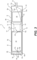
- FIG. 3 is a diagram of a device 10 with a matrix 100, in accordance with an example embodiment.
- the device is considered to be a 'heat-not-burn' device.
- the device 10 includes two sections: a power section 20 and a heating section 30.
- the power section 20 may be a rechargeable, non-disposable section, or alternatively the power section may be disposable.
- the heating section 30 may be disposable, or the heating section may instead be non-disposable.
- the heating section 30 of the device 10 includes a chamber 30b that includes the matrix 100.
- the matrix 100 includes the containing structure 103.
- the matrix 100 is in the form of the capsule 104.
- the heating section 30 is rechargeable and non-disposable.
- the capsule 104 and/or matrix 100 may be removable, and the capsule 104 and/or matrix 100 may allow for the flavoring system and/or nicotine to be added or recharged within the capsule 104 and/or matrix 100, so that the capsule 104 and/or matrix 100 can then be re-installed in the chamber 30b of the heating section 30.
- the capsule 104 and/or matrix 100 may be removable and replaceable with a new capsule 104 and/or matrix 100, where the capsule 104 and/or the matrix 100 may be disposable.
- the containing structure 103 of the capsule 104 may be removable, or remain affixed within the device 10, where only the matrix 100 may be removed and replaced from the containing structure 103, such that the containing structure 103 is reusable and the matrix 100 is replaceable.
- the heating section 30 may allow for access to the matrix 100 and/or the capsule 104 in order to allow a flavoring system or nicotine to be added or recharged within the matrix 100 and/or the capsule 104.
- the matrix 100 resides in or near an airflow path 124 that is defined by the device 10.
- This airflow path 124 may be formed, for instance, by defining one or more air inlets 116 in the housing 30a of the heating section 30, with an airflow exit provided by a mouthpiece 112 (e.g., air outlet).
- the airflow path 124 may pass across the matrix 100, or directly through the matrix 100.
- the heating section 30 allows a bypass airflow path 124a to pass across and/or completely circumvent the matrix 100. This embodiment may be accomplished by, for instance, providing a gap 128 between the matrix 100 and/or the containing structure 103 of the capsule 104 and an inner surface of the housing 30a of the heating section 30.
- this bypass airflow 124a may include an entrained aerosol just as a downstream aerosol 124b (that passed through the matrix 100) also includes an aerosol, if the bypass airflow 124a passes across an exposed surface of the matrix 100.
- the heating section 30 allows the entire airflow path 124 to pass through the matrix 100, such that a bypass airflow 124a is not present. That is to say, the gap 128 of FIG. 3 would be removed.
- a dilution air inlet 112a may be located downstream of the matrix 100, where the dilution air inlet 112a may allow ambient air to mix with the aerosol 124b and the bypass airflow 124a.
- a heating element 110 is included in the heating section 30.
- the heating element 110 is capable of heating the chamber 30b and the matrix 100 to an extent that the flavoring, nicotine and/or ingredients in a pre-aerosol formulation in the matrix 100 is at least partially extracted (e.g., aerosolized) to create the aerosol 124b (and the bypass airflow 124a that may contain aerosol) that is extracted from the matrix 100.
- the heating element 110 heats the chamber 30b and the matrix 100 to an extent that the matrix 100 and the flavoring, nicotine and/or pre-aerosol formulation remain below a combustion temperature. That is to say, in some example embodiments, the heating element 110 does not combust any material in the matrix 100, including the flavoring, nicotine and/or pre-aerosol formulation.
- the heating element 110 is a distance 122 apart from the matrix 100, such that the heating element 110 utilizes convection to heat air in the housing 30a to indirectly heat the matrix 100.
- the distance 122 is negligible and/or non-existent, such that the heating element 110 is nearly touching, or is in direct contact, with the matrix 100 or the containing structure 103 of the matrix 100.
- the heating element 110 uses both conduction and convection to heat the matrix 100.
- the heating element 110 is partially or fully insertable into some or all of the matrix 100 or the containing structure 103 of the matrix 100.
- the heating element 110 contacts or circumscribes one or more sides, or surrounds or nearly surrounds the matrix 100 and/or the containing structure 103.
- the housing 30a of the heating section 30 is made from a material that is heat-insulating (e.g., a thermal insulator).
- the housing 30a may be made from a metal, metal alloy, polymer, plastic, resin, other suitable heat-insulating materials, and combinations or sub-combinations thereof.
- the heating element 110 is formed of any suitable electrically resistive materials.
- the heating element 110 is in the form of a wire coil, a planar body, a ceramic body, a single wire, a cage of resistive wire, or any other suitable form that heats the matrix 100.
- the heating element 110 is made from a sintered ceramic material that includes metal particles infused within the ceramic.
- the heating element 110 is constructed of an iron-aluminide (e.g., FeAl or Fe 3 Al).
- the power section 20 includes one or more chambers 20b defined by the housing 20a, where the chamber 20b includes the power source 120.
- the power source 120 may be a battery.
- the power source 120 may be a Lithium-ion battery, or one of its variants, for example a Lithium-ion polymer battery.
- the battery may be a Nickel-metal hydride battery, a Nickel cadmium battery, a Lithium-manganese battery, a Lithium-cobalt battery, a fuel cell or a solar cell. Any other power sources or battery technology may be used.
- the power source 120 is rechargeable and re-useable, where the power source 120 is charged via an external source, solar power, etc. In another example embodiment, the power source 120 is not rechargeable and is therefore disposable.
- the power section 20 includes at least one sensor 106 (referred to as a "sensor," throughout the remainder of this document) and control circuitry 126.
- the sensor 106 can be located anywhere in the device 10.
- the control circuitry 126 has one or more electrical terminals 126a for electrically connecting the control circuitry 126 to the sensor 106 and other elements of the device 10.
- the sensor 106 is in a fluid communication path that includes the chamber 20b of the power section 20, the chamber 30b of the heating section 30, and one or more holes 114 that open into both chambers 20b/30b.
- the sensor 106 measures a pressure drop in this fluid communication path.
- the sensor 106 and control circuitry 126 may be mounted on a printed circuit board 108.
- the senor 106 and/or control circuitry 126 are positioned at a different location in the power section 20, other than the location that is shown in FIG. 3 , where the sensor 106 and/or control circuitry 126 may for instance be proximally near the hole 114 that communicates with both sections 20/30.
- the sensor 106 detects one or more parameters within the device 10 and sends one or more signals to the control circuitry 126.
- the control circuitry 126 in response to receiving one or more signal from the sensor 106 the control circuitry 126 closes an ⁇ electrical circuit' that provides an electrical current from the power source 120 to the heating element 110 to cause the heating element 110 to the heat the chamber 30b of the heating section 30 and/or the matrix 100.
- the ⁇ electrical circuit' of the device 10 includes the following: the power source 120, terminals 107a and 107b of the power source 120, electrical leads 109a and 109b connected to the terminals 107a/b, the control circuitry 126 and the electrical terminals 126a of the control circuitry 126, the heating element 110 and electrical leads 116a and 116b connected to the heating element 110.
- the electrical circuit may include the housing 20a of the power section 20 and/or the housing 30a of the heating section 30, where the housing 20a / 30a may take the place of, or be used in addition to, the electrical leads 109a/b and 116a/b within the electrical circuit of the device 10.
- the housings 20a/30a in FIG. 3 may be the same or different shapes, such as for example cylindrical, square, rectangular, triangular, polygonal, curved, irregular, etc.
- the sensor 106 generates an output signal indicative of a magnitude and direction of airflow 124 through the heating section 30, where the control circuitry 126 receives the sensor 106 output signal and determine if the following internal conditions exist: (1) a direction of the airflow 124 indicates a draw on the mouthpiece 112 (versus blowing air through the mouthpiece 112), and/or (2) a magnitude of the airflow 124 exceeds a threshold value.
- a direction of the airflow 124 indicates a draw on the mouthpiece 112 (versus blowing air through the mouthpiece 112)
- a magnitude of the airflow 124 exceeds a threshold value.
- only one condition may be sufficient to activate the heater, while in other examples, two conditions or all conditions may have to be met before activating the heater.
- control circuitry 126 electrically closes the electrical circuit to connect the power source 120 to the heating element 110, thereby activating the heating element 110 by sending an electrical current to the heating element 110.
- the sensor 106 generates a variable output signal that is in at least partial correlation with a magnitude of the pressure drop sensed by the sensor 106.
- control circuitry 126 may include, or be in electrical communication with, a measurement circuit 126b, where the measurement circuit 126b is capable of detecting a change in resistance or a temperature of the heating element 110, as discussed below in more detail.
- the control circuitry 126 may send a variable electrical current to the heating element 110 based on the variable output signal from the sensor 106.
- the sensor 106 may be a sensor as disclosed in "Electronic Smoke Apparatus," U.S. App. No. 14/793,453, filed on July 7, 2015 , or a sensor as disclosed in "Electronic Smoke,” U.S. Pat. 9,072,321, issued on July 7, 2015 , each of which are hereby incorporated by reference in their entirety into this document. Other type of sensors to detect an airflow may be used.
- the device 10 with the containing structure 103 and/or matrix 100 has a resistance to draw (RTD) between about 5 mm water to 150 mm of water.
- RTD resistance to draw
- Other RTD may be implemented, such as for example, in some embodiments, the RTD may be below 5 mm of water or above 150 mm of water. It should be understood that the RTD of the matrix 100 lessens over time as the matrix 100 is in operational use, and therefore the RTD of the device 10 also lessens over time while in operation.
- FIG. 4A is an illustration of a side-view of the matrix 100 in an insert (insertable rod) 406, in accordance with an example embodiment.
- the insert 406 includes at least three sections: a proximal end section 404 that includes the matrix 100, a middle section 408, and a distal end section that is a filter 410.
- the filter 410 in some example embodiments is a non-consumable filter that does not include a consumable substance (e.g., the 410 is devoid of a consumable substance).
- the insert 406 has a "plug-space-plug" configuration, from the standpoint that the middle section 408 is largely a section of open (void) space (e.g., wrapped by a tipping paper that can also wrap the other sections).
- the middle section 408 may include a flow restrictor 412 in the middle section 408.
- the flow restrictor 412 may be in the form of a tube with walls 412a, where an internal surface 412b of the tube walls forms a restricted flow channel with an internal diameter 422.
- the middle section 408 defines open spaces 414/416 that bracket the flow restrictor 412, such that the flow restrictor 412 does not reach the ends of the middle section 408.
- the flow restrictor 412 may reach both ends of the middle section 408, or may reach one end but not both ends of the middle section 408.
- the reduced internal diameter 422 of the flow restrictor 412 reduces an airflow cross-sectional area through the middle section 408 to control a RTD and an airflow through the insert 406.
- the filter 410 is a filter that may be, for instance, a cellulose acetate (CA) filter.
- CA cellulose acetate
- the filter 410 (or other filters described in various embodiments) may also contain nicotine, flavorants, etc.
- flavorant beads and/or crushable beads may be included in one or more of the sections.
- an airflow through the insert 406 flows in a direction that causes the airflow to enter and flow through the matrix 100, before passing through the middle section 408 and the filter 410.
- insert 406 may include less than three sections or more than two sections.
- one example may include a filter section and a matrix section as has been described, or another example may include a sections such as middle section 408 and a matrix section, and in other examples may then include three sections with additional spaces, sections such as middle section 408, filter sections and/or matrix sections.
- the insert 406 includes the containing structure 103 that spans the length of the insert 406, by covering the outer surfaces of the matrix 100, the middle section 408 and the filter 410 and/or any other sections that may form part of the insert 406.
- the only wrapping around the matrix 100, middle section 408, filter section 410 and/or any other sections that may form part of the insert 406, is a containing structure 103 without any other wrapping around each of the sections that form part of insert 406 (i.e., the sections being wrapped only by and connected by a single wrapping such as containing structure 103).
- the containing structure 103 is made from tipping paper.
- the containing structure 103 is made from any of the materials described in conjunction with the containing structure 103, included in the embodiments described herein.
- the ends 406a of the insert 406 are open (e.g., the containing structure 103 is only wrapped around insert 406 in a longitudinal direction, such that the containing structure 103 does not exist on the ends 406a of the rod 406).
- the containing structure 103 exists on the ends 406a of the insert 406 are made from any of the materials for the containing structure 103 of the example embodiments described herein.
- the insert 406 can be referred to as a "capsule" for purposes of this document.
- One or more sections may also have their own cover, and then the various sections may be connected together, either by another covering or by other structure.
- the diameter 420 of the insert 406 is about 7-10 mm, or about 8.6 mm.
- the internal (restricted) diameter 422 of the flow restrictor 412 is about 4-8 mm, or about 5 mm.
- a longitudinal length of the end section 404 with the matrix 100 is about 5-16 mm, or about 6 mm.
- a longitudinal length of the middle section (flow restriction section) 408 is about 12-25 mm, or about 12 mm.
- the spaces 414/416 of the middle section 408 may each have a longitudinal length of about 4 mm.
- a longitudinal length of the non-consumable filter 410 is about 6-9 mm, or about 6 mm.
- the RTD of the insert 406 is about 30 mm of water or less, or about 26 mm of water or less.
- the insert 406 has the following dimensions: the end section 404 with the matrix 100 has a longitudinal length of about 6 mm, the middle section 408 has a longitudinal length of about 12 mm with spaces 414/416 that are each about 4 mm long, and the non-consumable filter 410 has a longitudinal length of about 6 mm - with a RTD of the insert 406 being about 26 mm of water or less.
- the insert 406 is disposable, such that the insert 406 may be discarded following a depletion of the consumable substance within the matrix 100.
- FIG. 4B is an illustration of a side-view of the matrix 100 in another insert (insertable rod) 406b, in accordance with an example embodiment. Reference numbers in common with FIG. 4A are not described again here, for brevity sake.
- a flow restrictor 411 is in the middle section 408, where the flow restrictor 411 is a "hat" flow restrictor.
- the flow restrictor 411 relies on a brim 411a of the flow restrictor 411 to provide the reduced cross-sectional airflow through the flow restrictor 411, where an internal surface 411b of the flow restrictor 411 defines a channel with the restricted diameter 422.
- an airflow through the insert 406b flows in a direction that causes the airflow to enter and flow through the matrix 100, before passing through the middle section 408 and the non-consumable filter 410.
- the insert 406b may be referred to as a "capsule" for purposes of this document.
- FIG. 5 is a diagram of a device 10a with the matrix 100 in the insert 406, in accordance with an example embodiment.
- insert 406b is substituted for insert 406 in this device 10a.
- the insert 406 is insertable into a distal (downstream) end of the heating section 30 of the device 10a.
- the insert 406 may, for instance, be friction-fitted within the end of the heating section 30.
- the insert 406 extends, at least partially, from the distal end of the heating section 30, such that the non-consumable filter 410 remains exposed and extends from the heating section 30 once the insert 406 is fully inserted into the heating section 30.
- the non-consumable filter 410 may act as a mouthpiece for the device 10a.
- the insert 406 may be disposable, whereas the heating section 30 need not be disposable.
- FIG. 6 is a flow chart of a method of making the matrix 100, in accordance with an example embodiment.
- the filler material 105 is formed from a plant-based cellulose material. As described above, this plant-based cellulose material can either be a non-tobacco cellulose material or a tobacco cellulose.
- the filler material 105 is processed to create the matrix 100. In an example embodiment, this is accomplished by shredding the filler material 105 to form the strands 102 of the filler material 105, where the strands 102 are then combined and/or compressed to form the matrix 100 (as described above).
- the matrix 100 is contained (e.g., bound together) to form the capsule 104.
- this may be accomplished by holding the matrix 100 together using the containing structure 103.
- the containing structure 103 is made from a metal, metal alloy, polymer, plastic, resin, mesh, cellulose, plant-based cellulose, fabric, cotton, fibers, threads, other textiles, pulp, paper, tipping paper, other suitable materials capable of containing the matrix 100, or combinations, or sub-combinations, of these materials.
- the containing structure 103 is made from the filler material 105.
- the matrix 100 is included in the containing structure 103 of the insert 406/406b, where these same recited method steps apply to the insert 406/406b.
- the containing structure 103 is wrapped in a longitudinal direction around the contained matrix 100 without covering upstream and downstream ends of the matrix 100.
- the filler material 105 is infused with the consumable substance that includes the flavorant, nicotine and/or ingredients of a pre-aerosol formulation.
- the infusing of the consumable substance occurs as the filler material 105 is being formed, or after the filler material 105 is formed (as described above).
- the infusing of the consumable substance occurs as the filler material 105 is being processed into the matrix 100, or after the matrix 100 is formed (as described above).
- FIG. 7 is a flow chart of a method of making the device 10, in accordance with an example embodiment.
- the matrix 100 allows an airflow to contact at least a portion of the matrix 100. As described above, this may be accomplished by providing openings in the containing structure 103, with an inlet and outlet opening to allow the airflow to pass through at least a portion of the matrix 100.
- the containing structure 103 is porous, such that the airflow is free to penetrate the containing structure 103 and flow across, or flow through, at least a portion of the matrix 100.
- At least a portion of the containing structure 103 exposes a portion of the matrix 100 to open air, thereby allowing the airflow to contact and/or pass across at least a surface of the matrix 100.
- this same method step applies to the matrix 100 within the insert 406/406b, where the matrix 100 allows airflow to contact (e.g., flow through) at least a portion of the matrix 100 for use in the device 10a.
- step S202 the matrix 100 is inserted into the housing 30a of the device 10.
- step S204 an airflow path is established within the device 10. This may be accomplished by adding an air inlet 116 and a mouthpiece 112 to the device 10. In an example embodiment, the air inlet 116 and mouthpiece 112 are on either side of the matrix 100, such that the airflow path is forced to pass by, pass across, or pass through at least a portion of the matrix 100.
- this same method step applies to the insert 406/406b, where the insert 406/406b is inserted into the housing 30a of the heating section 30 of the device 10a - though in this embodiment, the airflow path may be between the air inlet 116 and the non-consumable filter 410 (as the mouthpiece 112 may not be included in the device 10a).
- the heating element 110 is positioned in the housing 30a in proximity (a heating proximity) to the matrix 100 and/or the containing structure 103 holding the matrix 100. This may include positioning the heating element 110 to be near or in contact with the matrix 100 and/or the containing structure 103, or this may include inserting at least a portion of the heating element 110 within the matrix 100 and/or the containing structure 103.
- embodiments of the invention comprise the following features:
Landscapes
- Chemical & Material Sciences (AREA)
- Chemical Kinetics & Catalysis (AREA)
- General Chemical & Material Sciences (AREA)
- Health & Medical Sciences (AREA)
- General Health & Medical Sciences (AREA)
- Toxicology (AREA)
- Life Sciences & Earth Sciences (AREA)
- Molecular Biology (AREA)
- Manufacture Of Tobacco Products (AREA)
- Manufacturing Of Micro-Capsules (AREA)
Applications Claiming Priority (3)
| Application Number | Priority Date | Filing Date | Title |
|---|---|---|---|
| US16/125,293 US11432581B2 (en) | 2018-09-07 | 2018-09-07 | Capsule containing a matrix, device with the matrix, and method of forming the matrix |
| EP19753575.0A EP3836804B1 (de) | 2018-09-07 | 2019-08-05 | Vorrichtung enthaltend einen heizschacht enthaltend ein kapsel enthaltend einen matrix |
| PCT/US2019/045096 WO2020050939A1 (en) | 2018-09-07 | 2019-08-05 | Capsule containing a matrix, device with the matrix, and method of forming the matrix |
Related Parent Applications (1)
| Application Number | Title | Priority Date | Filing Date |
|---|---|---|---|
| EP19753575.0A Division EP3836804B1 (de) | 2018-09-07 | 2019-08-05 | Vorrichtung enthaltend einen heizschacht enthaltend ein kapsel enthaltend einen matrix |
Publications (2)
| Publication Number | Publication Date |
|---|---|
| EP4473850A2 true EP4473850A2 (de) | 2024-12-11 |
| EP4473850A3 EP4473850A3 (de) | 2024-12-25 |
Family
ID=67660011
Family Applications (2)
| Application Number | Title | Priority Date | Filing Date |
|---|---|---|---|
| EP19753575.0A Active EP3836804B1 (de) | 2018-09-07 | 2019-08-05 | Vorrichtung enthaltend einen heizschacht enthaltend ein kapsel enthaltend einen matrix |
| EP24186044.4A Pending EP4473850A3 (de) | 2018-09-07 | 2019-08-05 | Vorrichtung enthaltend einen heizschacht enthaltend ein kapsel enthaltend einen matrix |
Family Applications Before (1)
| Application Number | Title | Priority Date | Filing Date |
|---|---|---|---|
| EP19753575.0A Active EP3836804B1 (de) | 2018-09-07 | 2019-08-05 | Vorrichtung enthaltend einen heizschacht enthaltend ein kapsel enthaltend einen matrix |
Country Status (3)
| Country | Link |
|---|---|
| US (3) | US11432581B2 (de) |
| EP (2) | EP3836804B1 (de) |
| WO (1) | WO2020050939A1 (de) |
Families Citing this family (3)
| Publication number | Priority date | Publication date | Assignee | Title |
|---|---|---|---|---|
| WO2021110766A1 (en) * | 2019-12-02 | 2021-06-10 | Jt International Sa | E-liquid composition comprising 1, 3-propanediol below 50% by weight of the composition |
| US11812785B2 (en) * | 2020-06-23 | 2023-11-14 | Altria Client Services Llc | Capsules including internal heaters, heat-not-burn (HNB) aerosol-generating devices, and methods of generating an aerosol |
| US12053022B2 (en) * | 2021-01-04 | 2024-08-06 | Altria Client Services Llc | Capsules with integrated mouthpieces, heat-not-burn (HNB) aerosol-generating devices, and methods of generating an aerosol |
Citations (1)
| Publication number | Priority date | Publication date | Assignee | Title |
|---|---|---|---|---|
| US9072321B2 (en) | 2009-09-18 | 2015-07-07 | Minilogic Device Corporation Ltd. | Electronic smoke |
Family Cites Families (100)
| Publication number | Priority date | Publication date | Assignee | Title |
|---|---|---|---|---|
| US3255760A (en) | 1962-08-03 | 1966-06-14 | Kimberly Clark Co | Tobacco product which produces less tars |
| GB1055473A (en) | 1963-10-01 | 1967-01-18 | Celanese Corp | Tobacco substitute and products comprising the same |
| US3640285A (en) | 1966-11-21 | 1972-02-08 | Sutton Res Corp | Cigarette paper and method for preparation |
| ZA694055B (en) | 1968-06-17 | 1971-01-27 | Celanese Corp | Filter |
| US4210158A (en) | 1978-12-26 | 1980-07-01 | International Flavors & Fragrances Inc. | 5-Isopropyl-3-nonene-2,8-dione as flavorant and as a flavor enhancer in conjunction with smoking tobacco and smoking tobacco articles |
| US4357950A (en) | 1980-05-27 | 1982-11-09 | American Filtrona Corporation | Tobacco smoke filter having improved tar/carbon monoxide ratio |
| US4649944A (en) | 1982-09-30 | 1987-03-17 | Philip Morris Incorporated | Filter cigarette |
| US4938238A (en) | 1985-08-26 | 1990-07-03 | R. J. Reynolds Tobacco Company | Smoking article with improved wrapper |
| US4889143A (en) | 1986-05-14 | 1989-12-26 | R. J. Reynolds Tobacco Company | Cigarette rods and filters containing strands provided from sheet-like materials |
| US5025814A (en) | 1987-05-12 | 1991-06-25 | R. J. Reynolds Tobacco Company | Cigarette filters containing strands of tobacco-containing materials |
| US4903714A (en) | 1987-08-25 | 1990-02-27 | R. J. Reynolds Tobacco Company | Smoking article with improved mouthend piece |
| US5005593A (en) | 1988-01-27 | 1991-04-09 | R. J. Reynolds Tobacco Company | Process for providing tobacco extracts |
| US4807809A (en) | 1988-02-12 | 1989-02-28 | R. J. Reynolds Tobacco Company | Rod making apparatus for smoking article manufacture |
| US4936920A (en) | 1988-03-09 | 1990-06-26 | Philip Morris Incorporated | High void volume/enhanced firmness tobacco rod and method of processing tobacco |
| US5360023A (en) | 1988-05-16 | 1994-11-01 | R. J. Reynolds Tobacco Company | Cigarette filter |
| US5129409A (en) | 1989-06-29 | 1992-07-14 | R. J. Reynolds Tobacco Company | Extruded cigarette |
| US5105836A (en) | 1989-09-29 | 1992-04-21 | R. J. Reynolds Tobacco Company | Cigarette and smokable filler material therefor |
| US5074320A (en) | 1989-10-26 | 1991-12-24 | R. J. Reynolds Tobacco Company | Cigarette and cigarette filter |
| US5269327A (en) | 1989-12-01 | 1993-12-14 | Philip Morris Incorporated | Electrical smoking article |
| US5060669A (en) | 1989-12-18 | 1991-10-29 | R. J. Reynolds Tobacco Company | Tobacco treatment process |
| US5396911A (en) * | 1990-08-15 | 1995-03-14 | R. J. Reynolds Tobacco Company | Substrate material for smoking articles |
| US5348027A (en) | 1991-02-14 | 1994-09-20 | R. J. Reynolds Tobacco Company | Cigarette with improved substrate |
| US5203355A (en) | 1991-02-14 | 1993-04-20 | R. J. Reynolds Tobacco Company | Cigarette with cellulosic substrate |
| US5505214A (en) | 1991-03-11 | 1996-04-09 | Philip Morris Incorporated | Electrical smoking article and method for making same |
| GB9303583D0 (en) | 1993-02-23 | 1993-04-07 | British American Tobacco Co | Improvements relating to smoking articles |
| US5396909A (en) | 1993-12-16 | 1995-03-14 | R. J. Reynolds Tobacco Company | Smoking article filter |
| JP3420359B2 (ja) | 1994-10-21 | 2003-06-23 | ダイセル化学工業株式会社 | たばこ煙用フィルター素材、繊維状セルロースエステル及びその製造方法 |
| US5829453A (en) | 1995-06-09 | 1998-11-03 | R. J. Reynolds Tobacco Company | Low-density tobacco filler and a method of making low-density tobacco filler and smoking articles therefrom |
| US5685323A (en) | 1995-07-24 | 1997-11-11 | R. J. Reynolds Tobacco Company | Disposable filter attachment for smoking articles |
| GB9605116D0 (en) | 1996-03-07 | 1996-05-08 | British American Tobacco Co | Smokable filler material for smoking articles |
| PL203915B1 (pl) | 2002-10-31 | 2009-11-30 | Philip Morris Prod | Elektrycznie podgrzewany papieros przeznaczony do stosowania w elektrycznym systemie palenia papierosów, sposób wytwarzania elektrycznie podgrzewanego papierosa przeznaczonego do stosowania w elektrycznym systemie palenia papierosów, sposób palenia elektrycznie podgrzewanego papierosa i elektryczny system palenia papierosów |
| AU2004269986A1 (en) * | 2003-09-08 | 2005-03-17 | Pfizer Consumer Healthcare Health Ab | Nicotine formulations and use thereof |
| JP3958268B2 (ja) | 2003-09-09 | 2007-08-15 | ファナック株式会社 | ノズルタッチ機構 |
| US20050263165A1 (en) | 2004-05-27 | 2005-12-01 | Oh Soo H | Tobacco leaf substitute |
| US7578298B2 (en) | 2005-02-04 | 2009-08-25 | Philip Morris Usa Inc. | Flavor capsule for enhanced flavor delivery in cigarettes |
| US7878962B2 (en) | 2005-05-03 | 2011-02-01 | Philip Morris Usa Inc. | Cigarettes and filter subassemblies with squeezable flavor capsule and methods of manufacture |
| US7647932B2 (en) | 2005-08-01 | 2010-01-19 | R.J. Reynolds Tobacco Company | Smoking article |
| US20070056600A1 (en) | 2005-09-14 | 2007-03-15 | R. J. Reynolds Tobacco Company | Filtered smoking article |
| US8157918B2 (en) | 2005-09-30 | 2012-04-17 | Philip Morris Usa Inc. | Menthol cigarette |
| WO2007053097A1 (en) | 2005-11-07 | 2007-05-10 | Njette Ab | Nicotine with a reduced content of nitrosamines . |
| US9220301B2 (en) | 2006-03-16 | 2015-12-29 | R.J. Reynolds Tobacco Company | Smoking article |
| PL2007233T3 (pl) | 2006-03-28 | 2020-03-31 | Philip Morris Products S.A. | Wyrób do palenia z ogranicznikiem |
| US8739802B2 (en) | 2006-10-02 | 2014-06-03 | R.J. Reynolds Tobacco Company | Filtered cigarette |
| US7726320B2 (en) | 2006-10-18 | 2010-06-01 | R. J. Reynolds Tobacco Company | Tobacco-containing smoking article |
| RU2462964C2 (ru) | 2006-11-29 | 2012-10-10 | Империал Тобэкко Канада Лимитед | Сигаретный фильтр с ароматическими частицами |
| GB0624321D0 (en) | 2006-12-05 | 2007-01-17 | British American Tobacco Co | Tobacco smoke filter and methods of making the same |
| TW200911138A (en) | 2007-03-09 | 2009-03-16 | Philip Morris Prod | Smoking articles with restrictor and aerosol former |
| TW200911141A (en) | 2007-03-09 | 2009-03-16 | Philip Morris Prod | Super recessed filter cigarette restrictor |
| US8186360B2 (en) | 2007-04-04 | 2012-05-29 | R.J. Reynolds Tobacco Company | Cigarette comprising dark air-cured tobacco |
| US8113215B2 (en) | 2007-06-21 | 2012-02-14 | Philip Morris Usa Inc. | Smoking article filter having liquid additive containing tubes therein |
| GB0809865D0 (en) | 2008-05-30 | 2008-07-09 | British American Tobacco Co | Filter for a smoking article |
| RU2010148804A (ru) | 2008-06-25 | 2012-07-27 | Джапан Тобакко Инк. (Jp) | Курительное изделие |
| GB0821803D0 (en) | 2008-12-01 | 2009-01-07 | British American Tobacco Co | Smoking article filter |
| GB0910373D0 (en) | 2009-06-16 | 2009-07-29 | Filtrona Int Ltd | Tabacco smoke filter |
| US8464726B2 (en) | 2009-08-24 | 2013-06-18 | R.J. Reynolds Tobacco Company | Segmented smoking article with insulation mat |
| US10420374B2 (en) | 2009-09-18 | 2019-09-24 | Altria Client Services Llc | Electronic smoke apparatus |
| GB0922253D0 (en) | 2009-12-21 | 2010-02-03 | British American Tobacco Co | Sheet filter materials with additives |
| AR081744A1 (es) | 2010-03-26 | 2012-10-17 | Philip Morris Prod | Filtro con adaptadores con espacio intermedio con bolita saborizada |
| US8839799B2 (en) | 2010-05-06 | 2014-09-23 | R.J. Reynolds Tobacco Company | Segmented smoking article with stitch-bonded substrate |
| GB201007946D0 (en) | 2010-05-12 | 2010-06-30 | British American Tobacco Co | Filter additive |
| GB201016387D0 (en) | 2010-09-29 | 2010-11-10 | Filtrona Int Ltd | Tobacco smoke filter |
| US20120125354A1 (en) | 2010-11-18 | 2012-05-24 | R.J. Reynolds Tobacco Company | Fire-Cured Tobacco Extract and Tobacco Products Made Therefrom |
| CA2837953C (en) | 2011-05-31 | 2020-06-16 | Philip Morris Products S.A. | Rods for use in smoking articles |
| RU2600911C2 (ru) | 2011-09-09 | 2016-10-27 | Филип Моррис Продактс С.А. | Фильтр курительного изделия с ограничивающим элементом и полостью |
| US20140224268A1 (en) | 2011-09-09 | 2014-08-14 | Philip Morris Products S.A. | Smoking article filter including polymeric insert |
| US8967155B2 (en) | 2011-11-03 | 2015-03-03 | Celanese Acetate Llc | Products of high denier per filament and low total denier tow bands |
| EP2625974A1 (de) | 2012-02-13 | 2013-08-14 | Philip Morris Products S.A. | Aerosolerzeugender Artikel mit einer geschmackserzeugenden Komponente |
| US9326547B2 (en) | 2012-01-31 | 2016-05-03 | Altria Client Services Llc | Electronic vaping article |
| US20140261486A1 (en) | 2013-03-12 | 2014-09-18 | R.J. Reynolds Tobacco Company | Electronic smoking article having a vapor-enhancing apparatus and associated method |
| GB2513639A (en) * | 2013-05-02 | 2014-11-05 | Nicoventures Holdings Ltd | Electronic cigarette |
| TWI649040B (zh) | 2013-05-07 | 2019-02-01 | 瑞士商菲利浦莫里斯製品股份有限公司 | 用於保持煙品的裝置及此裝置的使用 |
| TWI654942B (zh) | 2013-05-14 | 2019-04-01 | 瑞士商菲利浦莫里斯製品股份有限公司 | 包含液體傳送構件及包覆材的菸品 |
| WO2014207843A1 (ja) | 2013-06-26 | 2014-12-31 | トヨタ自動車株式会社 | 内燃機関の診断装置 |
| US20150000682A1 (en) | 2013-06-28 | 2015-01-01 | Qiuming Liu | Electronic cigarette |
| US10390562B2 (en) | 2013-07-23 | 2019-08-27 | Altria Client Services Llc | Electronic smoking article |
| US20150027468A1 (en) | 2013-07-25 | 2015-01-29 | Altria Client Services Inc. | Electronic smoking article |
| US9402422B2 (en) | 2013-11-01 | 2016-08-02 | Yuval Shenkal | Hybrid e-cigarette/vaporizer with exhale filter capability |
| GB201320231D0 (en) | 2013-11-15 | 2014-01-01 | British American Tobacco Co | Aerosol generating material and devices including the same |
| SI3076813T1 (sl) | 2013-12-05 | 2019-08-30 | Philip Morris Products S.A. | Netobačni izdelek, ki vsebuje nikotin |
| LT3082482T (lt) | 2013-12-20 | 2018-04-10 | Philip Morris Products S.A. | Rūkymo gaminys turintis filtrą, apimantį kapsulę |
| EP3089601B1 (de) * | 2013-12-31 | 2020-02-05 | Philip Morris Products S.A. | Rauchartikel mit durchflussbegrenzer in hohlröhre |
| UA120260C2 (uk) | 2013-12-31 | 2019-11-11 | Філіп Морріс Продактс С.А. | Курильний виріб з компонентом вивільнення рідини |
| MX390553B (es) | 2014-02-10 | 2025-03-20 | Philip Morris Products Sa | Un sistema generador de aerosol con una unidad de calentamiento permeable al fluido. |
| US20150335070A1 (en) | 2014-05-20 | 2015-11-26 | R.J. Reynolds Tobacco Company | Electrically-powered aerosol delivery system |
| EA201790930A1 (ru) | 2014-10-29 | 2017-08-31 | Олтриа Клайент Сервисиз Ллк | Картридж электронного вейпингового устройства |
| US20160135506A1 (en) * | 2014-11-19 | 2016-05-19 | Fontem Holdings 2 B.V. | Method, composition and apparatus for functionalization of aerosols from non combustible smoking articles |
| US9950858B2 (en) | 2015-01-16 | 2018-04-24 | R.J. Reynolds Tobacco Company | Tobacco-derived cellulose material and products formed thereof |
| WO2016159013A1 (ja) | 2015-04-02 | 2016-10-06 | 日本たばこ産業株式会社 | 香味吸引器 |
| EP3632490B1 (de) | 2015-05-06 | 2025-04-23 | Altria Client Services LLC | Verbrennungsfreie rauchvorrichtung und komponenten davon |
| TW201701781A (zh) | 2015-07-10 | 2017-01-16 | 菲利浦莫里斯製品股份有限公司 | 包括液體輸送元件的氣溶膠產生製品 |
| US11641874B2 (en) | 2015-09-09 | 2023-05-09 | R.J. Reynolds Tobacco Company | Flavor delivery article |
| US20170145634A1 (en) * | 2015-11-25 | 2017-05-25 | Verso Corporation | Composite paper pulp composition and method of making |
| EP3383460B1 (de) | 2015-11-30 | 2020-07-15 | Philip Morris Products S.a.s. | Nichtbrennbare rauchvorrichtung und elemente davon |
| US10433580B2 (en) | 2016-03-03 | 2019-10-08 | Altria Client Services Llc | Methods to add menthol, botanic materials, and/or non-botanic materials to a cartridge, and/or an electronic vaping device including the cartridge |
| US20170280769A1 (en) | 2016-04-04 | 2017-10-05 | Altria Client Services Llc | Electronic vaping device and kit |
| US10881139B2 (en) | 2016-07-07 | 2021-01-05 | Altria Client Services Llc | Non-combustible vaping element with tobacco insert |
| GB201615601D0 (en) | 2016-09-14 | 2016-10-26 | British American Tobacco Investments Ltd | Receptacle section |
| US20180106154A1 (en) | 2016-10-13 | 2018-04-19 | General Electric Company | Contoured bondcoat for environmental barrier coatings and methods for making contoured bondcoats for environmental barrier coatings |
| US10433585B2 (en) | 2016-12-28 | 2019-10-08 | Altria Client Services Llc | Non-combustible smoking systems, devices and elements thereof |
| CN108201169A (zh) | 2017-12-22 | 2018-06-26 | 云南养瑞科技集团有限公司 | 具有降低气流温度并补充有益成分的过滤单元 |
-
2018
- 2018-09-07 US US16/125,293 patent/US11432581B2/en active Active
-
2019
- 2019-08-05 WO PCT/US2019/045096 patent/WO2020050939A1/en not_active Ceased
- 2019-08-05 EP EP19753575.0A patent/EP3836804B1/de active Active
- 2019-08-05 EP EP24186044.4A patent/EP4473850A3/de active Pending
-
2022
- 2022-09-02 US US17/902,271 patent/US11950622B2/en active Active
-
2024
- 2024-03-27 US US18/618,735 patent/US20240237697A1/en active Pending
Patent Citations (1)
| Publication number | Priority date | Publication date | Assignee | Title |
|---|---|---|---|---|
| US9072321B2 (en) | 2009-09-18 | 2015-07-07 | Minilogic Device Corporation Ltd. | Electronic smoke |
Also Published As
| Publication number | Publication date |
|---|---|
| US20220408792A1 (en) | 2022-12-29 |
| WO2020050939A1 (en) | 2020-03-12 |
| US11950622B2 (en) | 2024-04-09 |
| EP3836804B1 (de) | 2024-07-10 |
| US20240237697A1 (en) | 2024-07-18 |
| US20200077701A1 (en) | 2020-03-12 |
| US11432581B2 (en) | 2022-09-06 |
| EP3836804A1 (de) | 2021-06-23 |
| EP4473850A3 (de) | 2024-12-25 |
Similar Documents
| Publication | Publication Date | Title |
|---|---|---|
| US12213518B2 (en) | Method of making E-vaping device with insert | |
| US20220354162A1 (en) | Method of forming filter with interstices for e-vaping device | |
| US20240237697A1 (en) | Capsule including one or more portions of filler material infused with at least one first substance | |
| CN113163856B (zh) | 非燃烧加热型吸烟物品以及电加热型吸烟系统 | |
| EP4140338A1 (de) | Tabakprodukt zur erwärmung ohne verbrennung, elektrisch beheiztes tabakprodukt und tabakmaterial zur erwärmung ohne verbrennung | |
| EP3911186B1 (de) | Nicht brennbares aerosolsystem und gehäuse für präaerosolformulierung | |
| CN113163855A (zh) | 非燃烧加热型吸烟物品、电加热型吸烟系统及非燃烧加热型吸烟物品的制造方法 | |
| US20250057233A1 (en) | An aerosol provision system and an article for use in an aerosol provision system | |
| RU2801131C2 (ru) | Электронное устройство для парения, содержащее вставку | |
| CN118678894A (zh) | 气溶胶生成组合物 | |
| RU2803912C2 (ru) | Фильтр для электронного устройства для парения, электронное устройство для парения с фильтром и способ образования фильтра | |
| BR112021002939B1 (pt) | Dispositivo de e-vaporização com uma inserção | |
| BR112021002224B1 (pt) | Filtro para um dispositivo de vaporização eletrônica, dispositivo de vaporização eletrônica com o filtro, e método de formação do filtro | |
| TW202021487A (zh) | 非燃燒加熱型吸煙物品、電力加熱型吸煙系統以及非燃燒加熱型吸煙物品之製造方法 |
Legal Events
| Date | Code | Title | Description |
|---|---|---|---|
| PUAI | Public reference made under article 153(3) epc to a published international application that has entered the european phase |
Free format text: ORIGINAL CODE: 0009012 |
|
| STAA | Information on the status of an ep patent application or granted ep patent |
Free format text: STATUS: THE APPLICATION HAS BEEN PUBLISHED |
|
| PUAL | Search report despatched |
Free format text: ORIGINAL CODE: 0009013 |
|
| AC | Divisional application: reference to earlier application |
Ref document number: 3836804 Country of ref document: EP Kind code of ref document: P |
|
| AK | Designated contracting states |
Kind code of ref document: A2 Designated state(s): AL AT BE BG CH CY CZ DE DK EE ES FI FR GB GR HR HU IE IS IT LI LT LU LV MC MK MT NL NO PL PT RO RS SE SI SK SM TR |
|
| AK | Designated contracting states |
Kind code of ref document: A3 Designated state(s): AL AT BE BG CH CY CZ DE DK EE ES FI FR GB GR HR HU IE IS IT LI LT LU LV MC MK MT NL NO PL PT RO RS SE SI SK SM TR |
|
| RIC1 | Information provided on ipc code assigned before grant |
Ipc: A24F 47/00 20200101ALI20241118BHEP Ipc: A24B 15/28 20060101ALI20241118BHEP Ipc: A24B 15/16 20200101AFI20241118BHEP |
|
| STAA | Information on the status of an ep patent application or granted ep patent |
Free format text: STATUS: REQUEST FOR EXAMINATION WAS MADE |
|
| 17P | Request for examination filed |
Effective date: 20250625 |
|
| STAA | Information on the status of an ep patent application or granted ep patent |
Free format text: STATUS: EXAMINATION IS IN PROGRESS |
|
| 17Q | First examination report despatched |
Effective date: 20251210 |