EP4472291A1 - Verfahren und vorrichtung zur steuerung von katastrophenroaming, endgerät und netzwerkseitige vorrichtung - Google Patents
Verfahren und vorrichtung zur steuerung von katastrophenroaming, endgerät und netzwerkseitige vorrichtung Download PDFInfo
- Publication number
- EP4472291A1 EP4472291A1 EP23746301.3A EP23746301A EP4472291A1 EP 4472291 A1 EP4472291 A1 EP 4472291A1 EP 23746301 A EP23746301 A EP 23746301A EP 4472291 A1 EP4472291 A1 EP 4472291A1
- Authority
- EP
- European Patent Office
- Prior art keywords
- disaster
- roaming
- terminal
- indication information
- message
- Prior art date
- Legal status (The legal status is an assumption and is not a legal conclusion. Google has not performed a legal analysis and makes no representation as to the accuracy of the status listed.)
- Pending
Links
Images




Classifications
-
- H—ELECTRICITY
- H04—ELECTRIC COMMUNICATION TECHNIQUE
- H04W—WIRELESS COMMUNICATION NETWORKS
- H04W4/00—Services specially adapted for wireless communication networks; Facilities therefor
- H04W4/90—Services for handling of emergency or hazardous situations, e.g. earthquake and tsunami warning systems [ETWS]
-
- H—ELECTRICITY
- H04—ELECTRIC COMMUNICATION TECHNIQUE
- H04W—WIRELESS COMMUNICATION NETWORKS
- H04W4/00—Services specially adapted for wireless communication networks; Facilities therefor
- H04W4/18—Information format or content conversion, e.g. adaptation by the network of the transmitted or received information for the purpose of wireless delivery to users or terminals
-
- H—ELECTRICITY
- H04—ELECTRIC COMMUNICATION TECHNIQUE
- H04W—WIRELESS COMMUNICATION NETWORKS
- H04W48/00—Access restriction; Network selection; Access point selection
- H04W48/02—Access restriction performed under specific conditions
- H04W48/04—Access restriction performed under specific conditions based on user or terminal location or mobility data, e.g. moving direction, speed
-
- H—ELECTRICITY
- H04—ELECTRIC COMMUNICATION TECHNIQUE
- H04W—WIRELESS COMMUNICATION NETWORKS
- H04W48/00—Access restriction; Network selection; Access point selection
- H04W48/18—Selecting a network or a communication service
-
- H—ELECTRICITY
- H04—ELECTRIC COMMUNICATION TECHNIQUE
- H04W—WIRELESS COMMUNICATION NETWORKS
- H04W60/00—Affiliation to network, e.g. registration; Terminating affiliation with the network, e.g. de-registration
- H04W60/04—Affiliation to network, e.g. registration; Terminating affiliation with the network, e.g. de-registration using triggered events
-
- H—ELECTRICITY
- H04—ELECTRIC COMMUNICATION TECHNIQUE
- H04W—WIRELESS COMMUNICATION NETWORKS
- H04W60/00—Affiliation to network, e.g. registration; Terminating affiliation with the network, e.g. de-registration
- H04W60/06—De-registration or detaching
-
- H—ELECTRICITY
- H04—ELECTRIC COMMUNICATION TECHNIQUE
- H04W—WIRELESS COMMUNICATION NETWORKS
- H04W76/00—Connection management
- H04W76/50—Connection management for emergency connections
-
- H—ELECTRICITY
- H04—ELECTRIC COMMUNICATION TECHNIQUE
- H04W—WIRELESS COMMUNICATION NETWORKS
- H04W8/00—Network data management
- H04W8/02—Processing of mobility data, e.g. registration information at HLR [Home Location Register] or VLR [Visitor Location Register]; Transfer of mobility data, e.g. between HLR, VLR or external networks
- H04W8/08—Mobility data transfer
-
- H—ELECTRICITY
- H04—ELECTRIC COMMUNICATION TECHNIQUE
- H04W—WIRELESS COMMUNICATION NETWORKS
- H04W8/00—Network data management
- H04W8/02—Processing of mobility data, e.g. registration information at HLR [Home Location Register] or VLR [Visitor Location Register]; Transfer of mobility data, e.g. between HLR, VLR or external networks
- H04W8/08—Mobility data transfer
- H04W8/12—Mobility data transfer between location registers or mobility servers
-
- H—ELECTRICITY
- H04—ELECTRIC COMMUNICATION TECHNIQUE
- H04W—WIRELESS COMMUNICATION NETWORKS
- H04W84/00—Network topologies
- H04W84/02—Hierarchically pre-organised networks, e.g. paging networks, cellular networks, WLAN [Wireless Local Area Network] or WLL [Wireless Local Loop]
- H04W84/04—Large scale networks; Deep hierarchical networks
- H04W84/042—Public Land Mobile systems, e.g. cellular systems
Definitions
- This application relates to the field of communication technologies, and specifically, to a disaster roaming control method and apparatus, a terminal, and a network side device.
- a network side may allow a terminal to perform disaster roaming, or may not allow a terminal to perform disaster roaming.
- MINT Management of Service Interruption
- Embodiments of this application provide a disaster roaming control method and apparatus, a terminal, and a network side device to resolve a problem that a behavior of the terminal is unclear in a case in which the terminal is not allowed to perform disaster roaming.
- a disaster roaming control method applied to a terminal.
- the method includes:
- a disaster roaming control method applied to a first network side device.
- the method includes: The first network side device sends first indication information to a terminal, where the first indication information indicates the terminal to disable the disaster roaming.
- a disaster roaming control method applied to a second network side device.
- the method includes:
- a disaster roaming control apparatus applied to a terminal.
- the apparatus includes:
- a disaster roaming control apparatus applied to a first network side device.
- the apparatus includes: a first sending module, configured to send first indication information to a terminal, where the first indication information indicates the terminal to disable disaster roaming.
- a disaster roaming control apparatus applied to a second network side device.
- the apparatus includes:
- a terminal includes a processor and a memory.
- the memory stores a program or instructions that can be run on the processor.
- the program or instructions are executed by the processor, a step of the method according to the first aspect is implemented.
- a terminal including a processor and a communication interface.
- the communication interface is configured to receive first indication information, where the first indication information indicates the terminal to disable disaster roaming.
- the processor is configured to perform a first operation based on the first indication information, where the first operation includes at least one of the following: deleting a disaster roaming-related terminal context; initiating a deregistration process; receiving a first message, where the first message includes at least one of the following: a terminal configuration update message, a deregistration request message, and a NAS rejection message; and selecting a PLMN.
- a network side device includes a processor and a memory.
- the memory stores a program or instructions that can be run on the processor.
- the program or instructions are executed by the processor, a step of the method according to the first aspect or a step of the method according to the third aspect is implemented.
- a network side device including a processor and a communication interface.
- the network side device is a first network side device, and the communication interface is configured to send first indication information to a terminal, where the first indication information indicates the terminal to disable disaster roaming; or the network side device is a second network side device, the communication interface is configured to receive second indication information, where the second indication information indicates the terminal to disable disaster roaming, and the processor is configured to perform a second operation based on the second indication information, where the second operation includes at least one of the following: sending a first message, where the first message includes at least one of the following: a terminal configuration update message, a deregistration request message, and a NAS rejection message; skipping sending a second disaster roaming list provided by a VPLMN, or sending an empty second disaster roaming list provided by a VPLMN; and deleting a disaster roaming-related terminal context.
- a communication system including at least one of a terminal, a first network side device, and a second network side device.
- the terminal may be configured to perform a step of the method according to the first aspect.
- the first network side device may be configured to perform a step of the method according to the second aspect.
- the second network side device may be configured to perform a step of the method according to the third aspect.
- a readable storage medium stores a program or instructions.
- the program or instructions are executed by the processor, a step of the method according to the first aspect is implemented, a step of the method according to the second aspect is implemented, or a step of the method according to the third aspect is implemented.
- a chip includes a processor and a communication interface.
- the communication interface is coupled to the processor.
- the processor is configured to run a program or instructions to implement a step of the method according to the first aspect, a step of the method according to the second aspect, or a step of the method according to the third aspect.
- a computer program/program product is provided.
- the computer program/program product is stored in a storage medium.
- the computer program/program product is executed by at least one processor to implement a step of the method according to the first aspect, a step of the method according to the second aspect, or a step of the method according to the third aspect.
- the terminal may perform the first operation based on the first indication information.
- the first indication information indicates the terminal to disable disaster roaming.
- the first operation includes at least one of the following: deleting the disaster roaming-related terminal context; initiating the deregistration process; receiving the first message, where the first message includes at least one of the following: the terminal configuration update message, the deregistration request message, and the NAS rejection message; and selecting the PLMN.
- the terminal disables disaster roaming, in other words, in a case in which the terminal is not allowed to perform disaster roaming, a behavior of the terminal can be clarified.
- a storage resource of the terminal can be saved; and/or by initiating the deregistration process, receiving the first message, and/or selecting the PLMN, the terminal can be prevented from residing in a forbidden network.
- first and second are used to distinguish between similar objects but do not indicate a particular order or sequence. It is to be understood that the terms used in such ways are interchangeable under appropriate circumstances, so that the embodiments of this application can be implemented in sequences other than those illustrated or described herein.
- the objects distinguished by “first” and “second” are usually of the same type, and a quantity of objects is not limited. For example, there may be one or a plurality of first objects.
- “and/or” used in this specification and the claims indicates at least one of the connected objects. The character “/” generally indicates an "or" relationship between associated objects.
- LTE Long Term Evolution
- LTE-A Long Term Evolution-Advanced
- LTE-A Long Term Evolution-Advanced
- CDMA code division multiple access
- TDMA time division multiple access
- FDMA frequency division multiple access
- OFDMA Orthogonal Frequency Division Multiple Access
- SC-FDMA single-carrier frequency division multiple access
- system and “network” in the embodiments of this application are often used interchangeably, and the described technologies not only can be applied to the foregoing systems and wireless technologies, but also can be applied to other systems and wireless technologies.
- the following describes a new radio (New Radio, NR) system for an illustration purpose, and NR terminologies are used in most of the following descriptions, but these technologies can also be applied to an application other than an NR system application, for example, a sixth generation (6 th Generation, 6G) communication system.
- NR New Radio
- FIG. 1 is a block diagram of a wireless communication system to which an embodiment of this application can be applied.
- the wireless communication system includes a terminal 11 and a network side device 12.
- the terminal 11 may be a terminal side device such as a mobile phone, a tablet computer (Tablet Personal Computer), a laptop computer (Laptop Computer) or a notebook computer, a personal digital assistant (Personal Digital Assistant, PDA), a palmtop computer, a netbook, an ultra-mobile personal computer (ultra-mobile personal computer, UMPC), a mobile internet device (Mobile Internet Device, MID), an augmented reality (augmented reality, AR)/a virtual reality (virtual reality, VR) device, a robot, a wearable device (Wearable Device), an in-vehicle device (Vehicle User Equipment, VUE), a pedestrian terminal (Pedestrian User Equipment, PUE), a smart household (a home device having a wireless communication function, such as a refrigerator, a television, a washing machine, or furniture), a game
- Wearable devices include: a smart watch, a smart bracelet, a smart headset, smart glasses, smart jewelry (a smart bangle, a smart brace lace, a smart ring, a smart necklace, a smart anklet, or a smart ankle chain), a smart wristband, and smart clothing. It should be noted that a specific type of the terminal 11 is not limited in this embodiment of this application.
- the network side device 12 may include an access network device or a core network device.
- the access network device may also be referred to as a radio access network device, a radio access network (Radio Access Network, RAN), a radio access network function, or a radio access network unit.
- RAN Radio Access Network
- the access network device may include a base station, a wireless local area network (Wireless Local Area Network, WLAN) access point, a Wi-Fi node, or the like.
- the base station may be referred to as a NodeB, an evolved NodeB (eNB), an access point, a base transceiver station (Base Transceiver Station, BTS), a radio station, a radio transceiver, a basic service set (Basic Service Set, BSS), an extended service set (Extended Service Set, ESS), a home NodeB, a home evolved NodeB, a transmitting receiving point (Transmitting Receiving Point, TRP), or another appropriate term in the field.
- the base station is not limited to a particular term provided that a same technical effect can be achieved.
- the core network device may include but is not limited to at least one of the following: a core network node, a core network function, a mobility management entity (Mobility Management Entity, MME), an access and mobility management function (Access and Mobility Management Function, AMF), a session management function (Session Management Function, SMF), a user plane function (User Plane Function, UPF), a policy control function (Policy Control Function, PCF), a policy and charging rules function (Policy and Charging Rules Function, PCRF), an edge application server discovery function (Edge Application Server Discovery Function, EASDF), unified data management (Unified Data Management, UDM), unified data repository (Unified Data Repository, UDR), a home subscriber server (Home Subscriber Server, HSS), a centralized network configuration (Centralized network configuration, CNC), a network repository function (Mobility Management Entity, MME), an access and mobility management function (Access and Mobility Management Function, AMF), a session management function (Session Management Function, SMF),
- disaster roaming may also be briefly referred to as DC (disaster condition) roaming.
- Disaster roaming indication information may also be briefly referred to as DC indication information.
- Code of a disaster roaming equipment indicator (Disaster Roaming Equipment Indicator, DREI) in the disaster roaming indication information is enable (enable)/disable (disable), which may also be briefly referred to as that the terminal enables (enable)/disables (disable) disaster roaming.
- a disaster inbound roamer (Disaster Inbound Roamer) is sometimes briefly referred to as UE.
- initiating a deregistration process may also be referred to as: initiating a deregistration request message, sending a deregistration request message, or the like.
- Problem 1 UE has performed disaster roaming. If a home public land mobile network (Home Public Land Mobile Network, HPLMN) needs the UE to update the disaster roaming indication as disable, what behaviors of the UE and a network are.
- HPLMN Home Public Land Mobile Network
- the problem 1 corresponds to a scenario 1.
- the scenario 1 is, for example, a disaster happens to the HPLMN, the HPLMN and a PLMN-1 have a disaster roaming agreement, and the UE roams to the PLMN-1 for disaster roaming.
- the HPLMN first configures enabling disaster roaming for the UE. After disaster roaming occurs, the UE performs disaster roaming based on an enable indication. Subsequently, because, for example, the disaster roaming agreement (agreement) of the HPLMN and the PLMN-1 changes, or subscription information of the UE changes, and the HPLMN does not want the UE to continue using disaster roaming, what behaviors of the UE and the network are.
- Problem 2 In a roaming scenario, the UE has performed disaster roaming. If the HPLMN needs the UE to update the disaster roaming indication into disable, what behaviors of the UE and the network are.
- the problem 2 corresponds to a scenario 2.
- the scenario 2 is, for example, the UE normally roams from the HPLMN to a visited public land mobile network (Visited Public Land Mobile Network, VPLMN)-1.
- VPLMN Visited Public Land Mobile Network
- a disaster happens to the VPLMN-1, the VPLMN-1 and a PLMN-2 have a disaster roaming agreement, and the UE roams to the PLMN-2 for disaster roaming.
- the HPLMN first configures enabling disaster roaming for the UE.
- the UE normally roams to the VPLMN-1.
- the UE performs disaster roaming based on an enable indication, and performs disaster registration on the PLMN-2.
- the HPLMN does not want the UE to continue using disaster roaming, what behaviors of the UE and the network are.
- Problem 3 The UE has not performed disaster roaming. In a roaming scenario, if the HPLMN needs the UE to update the disaster roaming indication into disable, what behaviors of the UE and the network are.
- the problem 3 corresponds to a scenario 3.
- the scenario 3 is, for example, the UE normally roams from the HPLMN to the VPLMN-1. In this case, the UE has not performed disaster roaming. Next, because, for example, the subscription information of the UE changes, and the HPLMN does not want the UE to continue enabling disaster roaming, what behaviors of the UE and the network are.
- FIG. 2 is a flowchart of a disaster roaming control method according to an embodiment of this application. The method is performed by a terminal. As shown in FIG. 2 , the method includes the following steps.
- Step 21 The terminal receives first indication information.
- the first indication information indicates the terminal to disable (disable) disaster roaming.
- the disabling disaster roaming may be understood as not allowing the terminal to perform disaster roaming.
- the terminal may receive the first indication information from an HPLMN.
- the receiving the first indication information from an HPLMN may be understood as receiving the first indication information from a network function of the HPLMN.
- Step 22 The terminal performs a first operation based on the first indication information.
- the first operation may include at least one of the following:
- the first message is a NAS message.
- the terminal wants to receive the NAS message, the terminal needs to be in a connected mode, for example, a 5G mobility management (Mobility Management, MM)-CONNECTED mode. If the terminal is in an idle mode, for example, a 5GMM-IDLE mode, whether a network pages the terminal depends on a policy of the network or a local configuration of the network.
- a 5G mobility management Mobility Management, MM
- 5GMM-IDLE whether a network pages the terminal depends on a policy of the network or a local configuration of the network.
- the terminal after performing a high-priority network searching, the terminal selects the PLMN. For example, when the terminal is in the idle mode, for example, the 5GMM-IDLE mode, the terminal finds another PLMN (including an available PLMN and a forbidden PLMN) through high-priority network searching, and then selects the PLMN.
- the terminal finds another PLMN (including an available PLMN and a forbidden PLMN) through high-priority network searching, and then selects the PLMN.
- the terminal may select the PLMN in a 5GMM-registered (REGISTERED) mode or a 5GMM-deregistered (DEREGISTERED) mode.
- REGISTERED 5GMM-registered
- DEREGISTERED 5GMM-deregistered
- the terminal may perform at least one of the following: deleting the disaster roaming-related terminal context, initiating the deregistration process, receiving the first message, and selecting the PLMN.
- the terminal may delete the disaster roaming-related terminal context.
- the terminal may receive the first message from the network (for example, the PLMN-1 or the PLMN-2) to which the terminal performs disaster roaming, that is, receive the terminal configuration update message, the deregistration request message, and/or the NAS rejection message to avoid residing in the forbidden network.
- the PLMN-1 or the PLMN-2 has received second indication information that is sent by the HPLMN and that indicates the terminal to disable disaster roaming.
- the terminal may perform the first operation based on the first indication information.
- the first indication information indicates the terminal to disable disaster roaming.
- the first operation includes at least one of the following: deleting the disaster roaming-related terminal context; initiating the deregistration process; receiving the first message, where the first message includes at least one of the following: the terminal configuration update message, the deregistration request message, and the NAS rejection message; and selecting the PLMN.
- the terminal disables disaster roaming, in other words, in a case in which the terminal is not allowed to perform disaster roaming, a behavior of the terminal can be clarified.
- a storage resource of the terminal can be saved; and/or by initiating the deregistration process, receiving the first message, and/or selecting the PLMN, the terminal can be prevented from residing in a forbidden network.
- the initiating the deregistration process may include: In a case in which the terminal is executing a first service, the terminal initiates the deregistration process after the first service ends.
- the first service may be set based on an actual requirement, for example, may be a terminal-specific service. In this way, a case in which the first service that is being executed by the terminal is interrupted due to initiation of the deregistration process can be avoided.
- the first service may include at least one of the following: an emergency protocol data unit (Protocol Data Unit, PDU) session and a high-priority service.
- PDU Protocol Data Unit
- the terminal After receiving the first indication information, if the terminal is performing an emergency PDU session and/or a high-priority service, the terminal initiates the deregistration process after the emergency PDU session is released and/or the high-priority service ends.
- the disaster roaming-related terminal context may be deleted in an appropriate occasion.
- the deleting the disaster roaming-related terminal context may include at least one of the following:
- the disaster roaming-related terminal context may include a disaster roaming-related configuration parameter.
- the disaster roaming-related configuration parameter may include at least one of the following:
- the disaster roaming-related terminal context may further include a terminal context of a network in which the terminal is located after performing disaster roaming, for example, a globally unique temporary UE identity (Globally Unique Temporary UE Identity, GUTI) assigned by the network or disaster roaming area information.
- the disaster roaming area information is, for example, a tracking area (Tracking Area, TA) list (TA list) or a cell identity (cell ID).
- the HPLMN and/or the VPLMN may perform a disaster-related parameter configuration for the terminal.
- the terminal configuration update message may include third indication information, where the third indication information indicates at least one of the following:
- the terminal may learn of a configuration update reason by using the third indication information in the terminal configuration update message.
- content indicated by the third indication information may be direct or indirect.
- the third indication information may directly indicate disaster roaming not allowed/disaster roaming network unavailable, or may indicate current network unavailable/service not allowed.
- the third indication information includes one or more cause values.
- the cause value is a newly added cause value, indicating at least one of the following: disaster roaming not allowed and disaster roaming network unavailable; or the cause value is an existing cause value, indicating at least one of the following: network unavailable and service not allowed.
- the terminal configuration update message may include: an empty second disaster roaming list provided by the VPLMN indicating the terminal to disable disaster roaming. For example, if the VPLMN has provided a disaster roaming list, an empty disaster roaming list is used for update for the terminal by using the terminal configuration update message.
- the receiving first indication information may include any one of the following:
- FIG. 3 is a flowchart of a disaster roaming control method according to an embodiment of this application.
- the method is performed by a first network side device.
- the first network side device is, for example, a network function in an HPLMN.
- the network function is, for example, a UDM, an AMF, or an SMF.
- the method includes the following steps.
- Step 31 The first network side device sends first indication information to a terminal.
- the first indication information indicates the terminal to disable (disable) disaster roaming.
- the disabling disaster roaming may be understood as not allowing the terminal to perform disaster roaming.
- the first indication information indicates the terminal to perform a first operation.
- the first operation may include at least one of the following:
- the terminal by sending the first indication information to the terminal, the terminal may be enabled to perform the first operation.
- the first indication information indicates the terminal to disable disaster roaming.
- the terminal disables disaster roaming, in other words, in a case in which the terminal is not allowed to perform disaster roaming, a behavior of the terminal can be clarified.
- a storage resource of the terminal can be saved; and/or by initiating the deregistration process, receiving the first message, and/or selecting the PLMN, the terminal can be prevented from residing in a forbidden network.
- control method may further include: The first network side device sends second indication information to a second network side device, where the second indication information indicates the terminal to disable disaster roaming.
- the second network side device is, for example, a network function in a PLMN in which the terminal is located after performing disaster roaming.
- the network function is, for example, a UDM, an AMF, or an SMF.
- the second indication information may include identification information of the terminal.
- the identification information of the terminal is optionally at least one of the following: a GUTI, a subscription concealed identifier (Subscription Concealed Identifier, SUCI), a permanent equipment identifier (Permanent Equipment Identifier, PEI), a temporary mobile subscription identifier (Temporary Mobile Subscription Identifier, TMSI), a generic public subscription identifier (Generic Public Subscription Identifier, GPSI), an international mobile station equipment identity (International Mobile station Equipment Identity, IMEI), an international mobile subscriber identity (International Mobile Subscriber Identity, IMSI), and the like.
- the sending first indication information to a terminal may include any one of the following:
- the first network side device may send a first configuration information to the terminal.
- the first configuration information is used to indicate a disaster-related parameter of the terminal.
- the disaster-related parameter may include at least one of the following:
- FIG. 4 is a flowchart of a disaster roaming control method according to an embodiment of this application.
- the method is performed by a second network side device.
- the second network side device is, for example, a network function in a PLMN (for example, a VPLMN-1 or a VPLMN-2) in which a terminal is located after performing disaster roaming.
- the network function is, for example, a UDM, an AMF, or an SMF.
- the method includes the following steps.
- Step 41 The second network side device receives second indication information.
- the second indication information indicates the terminal to disable (disable) disaster roaming.
- the disabling disaster roaming may be understood as not allowing the terminal to perform disaster roaming.
- Step 42 The second network side device performs a second operation based on the second indication information.
- the second operation may include at least one of the following:
- the first message is a NAS message. It should be noted that if the terminal wants to receive the NAS message, the terminal needs to be in a connected mode, for example, a 5GMM-CONNECTED mode. If the terminal is in an idle mode, for example, a 5GMM-IDLE mode, whether a network pages the terminal depends on a policy of the network or a local configuration of the network.
- the second disaster roaming list provided by the VPLMN may not be sent to the terminal, or the empty second disaster roaming list provided by the VPLMN may be sent to the terminal. For example, if the VPLMN has provided a disaster roaming list, an empty disaster roaming list provided by the VPLMN is used for update.
- the VPLMN may send indication information.
- the indication information indicates that the disaster roaming list that is used in a disaster condition (disaster condition) and that is provided by the VPLMN is false (false) or is set to disabled (disable).
- the sending a first message is specifically: sending the first message to the terminal.
- the terminal may or may not receive first indication information. This is not limited herein. That is, in a case in which the terminal has not received the first indication information, the terminal may further receive the first message from the second network side device, that is, receive the terminal configuration update message, the deregistration request message, and/or the NAS rejection message, to avoid residing in the forbidden network.
- the second network side device may perform the second operation based on the second indication information.
- the second indication information indicates the terminal to disable disaster roaming.
- the second operation includes at least one of the following: sending the first message, where the first message includes at least one of the following: the terminal configuration update message, the deregistration request message, and the NAS rejection message; skipping sending the second disaster roaming list provided by the VPLMN, or sending the empty second disaster roaming list provided by the VPLMN; and deleting the disaster roaming-related terminal context.
- the terminal disables disaster roaming, in other words, in a case in which the terminal is not allowed to perform disaster roaming, a behavior of the PLMN in which the terminal is located after disaster roaming can be clarified.
- the sending a first message may include: In a case in which the terminal is executing a second service, the second network side device sends the first message after the second service ends.
- the second service may be set based on an actual requirement, for example, may be a terminal-specific service. In this way, a case in which the second service that is being executed by the terminal is interrupted due to sending of the NAS rejection message can be avoided.
- the second service may include at least one of the following: an emergency PDU session and a high-priority service.
- the second network side device such as an AMF sends the NAS rejection message after the emergency PDU session is released and/or the high-priority service ends.
- the terminal configuration update message may include third indication information, where the third indication information indicates at least one of the following:
- the terminal may learn of a configuration update reason by using the third indication information in the terminal configuration update message.
- content indicated by the third indication information may be direct or indirect.
- the third indication information may directly indicate disaster roaming not allowed/disaster roaming network unavailable, or may indicate current network unavailable/service not allowed.
- the third indication information includes one or more cause values.
- the cause value is a newly added cause value, indicating at least one of the following: disaster roaming not allowed and disaster roaming network unavailable; or the cause value is an existing cause value, indicating at least one of the following: network unavailable and service not allowed.
- the disaster roaming-related terminal context may include a disaster roaming-related configuration parameter.
- the disaster roaming-related configuration parameter may include at least one of the following:
- a terminal context in the PLMN for example, a PLMN-1, in which the terminal is located after performing disaster roaming is different from a terminal context saved in the terminal.
- a terminal context saved in the PLMN-1 has no disaster roaming indication, and when the disaster roaming-related configuration parameter is deleted, a disaster roaming list provided by an HPLMN cannot be deleted.
- a disaster happens to the HPLMN, the HPLMN and the PLMN-1 have a disaster roaming agreement, and UE roams to the PLMN-1 for the disaster roaming; and the HPLMN notifies the UE to update the disaster roaming indication into disable.
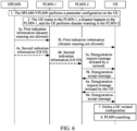
- a specific disaster roaming control process includes the following steps.
- Step 1 An HPLMN and/or a VPLMN performs a disaster-related parameter configuration on UE.
- the disaster roaming-related configuration parameter may be as described above. Details are not described herein again.
- Step 2 If a disaster happens to the HPLMN, according to a 1-1 configuration parameter and broadcast information of a PLMN-1, the UE registers with the PLMN-1 and enjoys a disaster roaming service, in other words, the UE performs disaster roaming in the PLMN-1, and enjoys a normal service of the PLMN-1.
- Step 3 The HPLMN sends first indication information, where the first indication information indicates that the UE does not allow disaster roaming, that is, indicates the UE to disable disaster roaming.
- the first indication information is forwarded by using the PLMN-1.
- a UDM of the HPLMN sends the first indication information to an AMF of the PLMN-1 by using the message Nudm_EventExposure_Notify, Ndm_SDM_ModifySubscription, or Nudm_SDM_Info.
- Step 4 Optionally, the HPLMN sends second indication information, where the second indication information indicates that the UE does not allow disaster roaming, that is, indicates the UE to disable disaster roaming.
- the second indication information further includes a UE identifier ID.
- the UE ID may be at least one of the following: a GUTI, an SUCI, a PEI, a TMSI, a GPSI, an IMEI, and an IMSI.
- Step 5 The PLMN-1 sends a NAS message, where the NAS message may include at least one of the following: a UE configuration update message, a deregistration request message, and a NAS rejection message.
- the PLMN-1 when the NAS message is a deregistration request message, the PLMN-1 sends the deregistration request message to the UE, as shown in 5a in FIG. 5 ; and receives a deregistration accept message from the UE, as shown in 5b in FIG. 5 .
- the UE configuration update message may further include third indication information.
- the third indication information indicates at least one of the following: disaster roaming not allowed; disaster roaming network unavailable; network unavailable; and service not allowed.
- the third indication information may include one or more cause values.
- the NAS message when the NAS message is a NAS rejection message, it indicates that the UE has initiated a NAS process such as a service request/registration request.
- the PLMN-1 should have responded to the corresponding service request/registration request, but because the second indication information is received, the PLMN-1 changes to send a corresponding rejection message to reject a NAS request of the UE, and indicates a reason for rejecting the UE, for example, current network unavailable or service not allowed.
- the NAS rejection message may be a service request rejection message, a registration request rejection message, or the like.
- the PLMN-1 (for example, an AMF in the PLMN-1) sends the NAS message after the emergency PDU session is released or the high-priority service ends.
- Step 6 As shown in 6a and 6b in FIG. 5 , the UE sends a deregistration request message to the PLMN-1, and the PLMN-1 replies with a deregistration accept message.
- step 5 and step 6 may be performed.
- the NAS message sent by the PLMN-1 is the deregistration request message, or the UE sends the deregistration request message.
- the PLMN-1 sends the NAS rejection message and/or the UE configuration update message, and the UE sends the deregistration request message.
- the UE if the UE is performing an emergency session or a high-priority service, the UE performs a deregistration process after the emergency PDU session is released or the high-priority service ends.
- Step 7 The UE deletes a disaster roaming-related UE context, including at least one of the following: at least one of the configuration parameters in step 1 and a UE context of the PLMN-1 (for example, a GUTI assigned by the PLMN-1 or disaster roaming area information (for example, a TA list or a cell ID)).
- a disaster roaming-related UE context including at least one of the following: at least one of the configuration parameters in step 1 and a UE context of the PLMN-1 (for example, a GUTI assigned by the PLMN-1 or disaster roaming area information (for example, a TA list or a cell ID)).
- Step 8 The UE searches for/selects a PLMN. It should be noted that the UE may select the PLMN in a 5GMM-REGISTERED mode or a 5GMM-DEREGISTERED mode.
- the UE normally roams from the HPLMN to the PLMN-1.
- a disaster happens to a VPLMN-1
- the VPLMN-1 and a PLMN-2 have a disaster roaming agreement
- the UE roams to the PLMN-2 for disaster roaming
- the HPLMN notifies the UE to update the disaster roaming indication into disable.
- a disaster roaming control process in the scenario 2 is basically the same as the disaster roaming control process in the scenario 1, and a difference lies in step 3 and step 4:
- the first indication information is sent by the HPLMN to the PLMN-1 (as shown in 3a in FIG. 6 ), and then is forwarded by the PLMN-1 to the UE (as shown in 3b in FIG. 6 ); and in step 4, the second indication information is sent by the HPLMN to the PLMN-1 (as shown in 4a in FIG. 6 ), and then is forwarded by the PLMN-1 to the PLMN-2 (as shown in 4b in FIG. 6 ).
- Other steps are the same as those in FIG. 5 . Details are not described herein again.
- a specific disaster roaming control process includes the following steps.
- Step 1 A PLMN-1 and an HPLMN have a roam agreement, and UE performs roaming, other than disaster roaming, in the PLMN-1.
- Step 2 The HPLMN sends first indication information, where the first indication information indicates that the UE does not allow disaster roaming, that is, indicates the UE to disable disaster roaming.
- Step 3 Optionally, the HPLMN sends second indication information, where the second indication information indicates that the UE does not allow disaster roaming, that is, indicates the UE to disable disaster roaming.
- the second indication information further includes a UE identifier ID.
- the UE ID may be at least one of the following: a GUTI, an SUCI, a PEI, a TMSI, a GPSI, an IMEI, and an IMSI.
- Step 4 Optionally, after receiving an indication from the HPLMN, the PLMN-1 performs at least one of the following:
- the terminal context includes the disaster roaming list provided by the VPLMN and a network resource of a terminal.
- Step 5 The UE deletes a disaster roaming-related configuration parameter.
- the disaster roaming control method provided in this embodiment of this application may be performed by a disaster roaming control apparatus.
- a disaster roaming control apparatus performs the disaster roaming control method is used to describe the disaster roaming control apparatus provided in the embodiments of this application.
- FIG. 8 is a diagram of a structure of a disaster roaming control apparatus according to an embodiment of this application. The apparatus is applied to a terminal. As shown in FIG. 8 , the disaster roaming control apparatus 80 includes:
- the first execution module 82 is specifically configured to: in a case in which the terminal is executing a first service, initiate the deregistration process after the first service ends.
- the first service includes at least one of the following: an emergency PDU session and a high-priority service.
- the first execution module 82 is specifically configured to perform at least one of the following:
- the terminal context includes a disaster roaming-related configuration parameter, where the disaster roaming-related configuration parameter includes at least one of the following:
- the terminal configuration update message includes third indication information, where the third indication information indicates at least one of the following:
- the third indication information includes one or more cause values.
- the terminal configuration update message includes an empty second disaster roaming list provided by the VPLMN.
- the first receiving module 81 is specifically configured to perform any one of the following:
- the disaster roaming control apparatus 80 may be an electronic device, for example, an electronic device having an operating system; or may be a component in an electronic device, for example, an integrated circuit or a chip.
- the electronic device may be a terminal, or may be a device other than a terminal.
- the terminal may include but is not limited to a type of the terminal 11 illustrated above. This is not specifically limited in this embodiment of this application.
- the disaster roaming control apparatus 80 provided in this embodiment of this application can implement the various processes implemented in the method embodiment in FIG. 2 , and the same technical effects can be achieved. To avoid repetition, details are not described herein again.
- FIG. 9 is a diagram of a structure of a disaster roaming control apparatus according to an embodiment of this application.
- the apparatus is applied to a first network side device.
- the disaster roaming control apparatus 90 includes: a first sending module 91, configured to send first indication information to a terminal, where the first indication information indicates the terminal to disable disaster roaming.
- the disaster roaming control apparatus 90 further includes: a second sending module, configured to send second indication information to a second network side device, where the second indication information indicates the terminal to disable disaster roaming.
- a second sending module configured to send second indication information to a second network side device, where the second indication information indicates the terminal to disable disaster roaming.
- the second indication information includes identification information of the terminal.
- the first sending module 91 is specifically configured to perform any one of the following:
- the disaster roaming control apparatus 90 further includes: a third sending module, configured to send first configuration information to the terminal, where the first configuration information is used to indicate a disaster-related parameter of the terminal.
- a third sending module configured to send first configuration information to the terminal, where the first configuration information is used to indicate a disaster-related parameter of the terminal.
- the disaster roaming control apparatus 90 provided in this embodiment of this application can implement the various processes implemented in the method embodiment in FIG. 3 , and the same technical effects can be achieved. To avoid repetition, details are not described herein again.
- FIG. 10 is a diagram of a structure of a disaster roaming control apparatus according to an embodiment of this application.
- the apparatus is applied to a second network side device.
- the disaster roaming control apparatus 100 includes:
- the second execution module 102 is specifically configured to: in a case in which it is determined that a terminal is executing a second service, send the first message after the second service ends.
- the second service includes at least one of the following: an emergency PDU session and a high-priority service.
- the terminal configuration update message includes third indication information, where the third indication information indicates at least one of the following:
- the third indication information includes one or more cause values.
- the terminal context includes a disaster roaming-related configuration parameter, where the disaster roaming-related configuration parameter includes at least one of the following:
- the disaster roaming control apparatus 100 provided in this embodiment of this application can implement the various processes implemented in the method embodiment in FIG. 4 , and the same technical effects can be achieved. To avoid repetition, details are not described herein again.
- an embodiment of this application further provides a communication device 110, including a processor 111 and a memory 112.
- the memory 112 stores a program or instructions that can be run on the processor 111.
- the steps in the method embodiment shown in FIG. 2 are implemented, and the same technical effects can be achieved.
- the various steps in the method embodiment shown in FIG. 3 or FIG. 4 are implemented, and the same technical effects can be achieved. To avoid repetition, details are not described herein again.
- An embodiment of this application further provides a terminal, including a processor and a communication interface.
- the communication interface is configured to receive first indication information.
- the first indication information indicates the terminal to disable disaster roaming.
- the processor is configured to perform a first operation based on the first indication information.
- the first operation includes at least one of the following: deleting a disaster roaming-related terminal context; initiating a deregistration process; receiving a first message, where the first message includes at least one of the following: a terminal configuration update message, a deregistration request message, and a NAS rejection message; and selecting a PLMN.
- the terminal embodiment corresponds to the foregoing method embodiment on the terminal side.
- the implementation processes and implementations of the foregoing method embodiment are all applicable to the terminal embodiment, and the same technical effects can be achieved.
- FIG. 12 is a diagram of a hardware structure of a terminal according to an embodiment of this application.
- the terminal 1200 includes but is not limited to at least some of a radio frequency unit 1201, a network module 1202, an audio output unit 1203, an input unit 1204, a sensor 1205, a display unit 1206, a user input unit 1207, an interface unit 1208, a memory 1209, a processor 1210, and the like.
- the terminal 1200 may further include a power supply (for example, a battery) that powers various components.
- the power supply may be logically connected to the processor 1210 through a power management system, to implement functions such as charging, discharging, and power consumption management through the power management system.
- the structure of the terminal shown in FIG. 12 does not constitute any limitation on the terminal.
- the terminal may include more or fewer components than those shown in the figure, or some components may be combined, or a different component arrangement may be used. Details are not described herein.
- the input unit 1204 may include a graphics processing unit (Graphics Processing Unit, GPU) 12041 and a microphone 12042.
- the graphics processor 12041 processes image data of a static picture or a video obtained by an image capturing apparatus (for example, a camera) in a video capturing mode or an image capturing mode.
- the display unit 1206 may include a display panel 12061.
- the display panel 12061 can be configured in a form of a liquid crystal display, an organic light-emitting diode, or the like.
- the user input unit 1207 includes at least one of a touch control panel 12071 and another input device 12072.
- the touch control panel 12071 is also referred to as a touchscreen.
- the touch control panel 12071 may include a touch detection apparatus and a touch controller.
- the another input device 12072 may include but is not limited to a physical keyboard, a function key (for example, a volume control key or an on/off key), a trackball, a mouse, and a joystick. Details are not described herein.
- the radio frequency unit 1201 may transmit the downlink data to the processor 1210 for processing.
- the radio frequency unit 1201 may send uplink data to the network side device.
- the radio frequency unit 1201 includes but is not limited to an antenna, an amplifier, a transceiver, a coupler, a low noise amplifier, a duplexer, and the like.
- the memory 1209 may be configured to store a software program or instructions and various data.
- the memory 1209 may mainly include a first storage area storing a program or instructions and a second storage area storing data.
- the first storage area may store an operating system, an application program or instructions (for example, an audio play function or an image play function) required by at least one function, and the like.
- the memory 1209 may include a volatile memory or a nonvolatile memory, or the memory 1209 may include both a volatile memory and a nonvolatile memory.
- the nonvolatile memory may be a read-only memory (Read-Only Memory, ROM), a programmable read-only memory (Programmable ROM, PROM), an erasable programmable read-only memory (Erasable PROM, EPROM), an electrically erasable programmable read-only memory (Electrically EPROM, EEPROM), or a flash memory.
- ROM Read-Only Memory
- PROM programmable read-only memory
- Erasable PROM Erasable PROM
- EPROM electrically erasable programmable read-only memory
- EEPROM electrically erasable programmable read-only memory
- the volatile memory may be a random access memory (Random Access Memory, RAM), a static random access memory (Static RAM, SRAM), a dynamic random access memory (Dynamic RAM, DRAM), a synchronous dynamic random access memory (Synchronous DRAM, SDRAM), a double data rate synchronous dynamic random access memory (Double Data Rate SDRAM, DDRSDRAM), an enhanced synchronous dynamic random access memory (Enhanced SDRAM, ESDRAM), a synchronous link dynamic random access memory (Synch link DRAM, SLDRAM), or a direct rambus random access memory (Direct Rambus RAM, DRRAM).
- RAM Random Access Memory
- SRAM static random access memory
- DRAM dynamic random access memory
- DRAM synchronous dynamic random access memory
- SDRAM double data rate synchronous dynamic random access memory
- Enhanced SDRAM, ESDRAM enhanced synchronous dynamic random access memory
- Synch link DRAM, SLDRAM synchronous link dynamic random access memory
- Direct Rambus RAM Direct Rambus RAM
- DRRAM direct Rambus RAM
- the processor 1210 may include one or more processing units.
- the processor 1210 is integrated with an application processor and a modem processor.
- the application processor mainly processes an operation related to an operating system, a user interface, an application program, and the like.
- the modem processor mainly processes a wireless communication signal, for example, a baseband processor signal. It can be understood that the modem processor may alternatively not be integrated into the processor 1210.
- the radio frequency unit 1201 is configured to receive first indication information, where the first indication information indicates the terminal to disable disaster roaming.
- the processor 1210 is configured to perform a first operation based on the first indication information.
- the first operation includes at least one of the following: deleting a disaster roaming-related terminal context; initiating a deregistration process; receiving a first message, where the first message includes at least one of the following: a terminal configuration update message, a deregistration request message, and a NAS rejection message; and selecting a PLMN.
- the terminal 1200 provided in this embodiment of this application can implement the various processes implemented in the method embodiment in FIG. 2 , and the same technical effects can be achieved. To avoid repetition, details are not described herein again.
- An embodiment of this application further provides a network side device, including a processor and a communication interface.
- the network side device is a first network side device, and the communication interface is configured to send first indication information to a terminal, where the first indication information indicates the terminal to disable disaster roaming; or the network side device is a second network side device, the communication interface is configured to receive second indication information, where the second indication information indicates the terminal to disable disaster roaming, and the processor is configured to perform a second operation based on the second indication information, where the second operation includes at least one of the following: sending a first message, where the first message includes at least one of the following: a terminal configuration update message, a deregistration request message, and a NAS rejection message; skipping sending a second disaster roaming list provided by a VPLMN, or sending an empty second disaster roaming list provided by a VPLMN; and deleting a disaster roaming-related terminal context.
- the network side device embodiment corresponds to the foregoing network side device method embodiment.
- an embodiment of this application further provides a network side device.
- the network side device 130 includes: a processor 131, a network interface 132, and a memory 133.
- the network interface 132 is, for example, a common public radio interface (common public radio interface, CPRI).
- the network side device 130 in this embodiment of the present invention further includes instructions or a program that is stored on the memory 133 and that can be run on the processor 131.
- the processor 131 invokes the instructions or program in the memory 133 to perform the method performed by the modules shown in FIG. 9 or FIG. 10 , and the same technical effects can be achieved. To avoid repetition, details are not described herein again.
- An embodiment of this application further provides a readable storage medium.
- the readable storage medium stores a program or instructions.
- the program or instructions are executed by a processor, the processes in the disaster roaming control method embodiment are implemented, and the same technical effects can be achieved. To avoid repetition, details are not described herein again.
- the processor is the processor in the terminal in the foregoing embodiment.
- the readable storage medium includes a computer-readable storage medium, for example, a computer read-only memory ROM, a random access memory RAM, a floppy disk, or an optical disc.
- An embodiment of this application further provides a chip.
- the chip includes a processor and a communication interface.
- the communication interface is coupled to the processor.
- the processor is configured to run a program or instructions to implement the processes in the disaster roaming control method embodiment, and the same technical effects can be achieved. To avoid repetition, details are not described herein again.
- the chip in this embodiment of this application may also be referred to as a system-level chip, a system chip, a chip system, a system-on-a-chip chip, or the like.
- An embodiment of this application further provides a computer program product.
- the computer program product is stored in a storage medium, the computer program product is executed by at least one processor to implement the processes in the disaster roaming control method embodiment, and the same technical effects can be achieved. To avoid repetition, details are not described herein again.
- An embodiment of this application further provides a communication system, including: a terminal, a first network side device, and a second network side device.
- the terminal may be configured to perform a step of the methods related to the terminal in FIG. 2 and various embodiments of this application.
- the first network side device may be configured to perform a step of the methods related to the first network side device in FIG. 3 and various embodiments of this application.
- the second network side device may be configured to perform a step of the methods related to the second network side device in FIG. 4 and various embodiments of this application.
- the term "comprise”, “include”, or any other variants thereof are intended to encompass in a non-exclusive mode, so that a process, a method, an object, or an apparatus including a series of elements not only includes those elements, but also includes other elements that are not explicitly listed, or elements that are inherent to such a process, a method, an object, or an apparatus.
- An element defined by the phrase “including a " does not exclude the presence of the same element in the process, method, object, or apparatus including the element, without more restrictions.
- the methods in the foregoing embodiments can be implemented by software plus a necessary general hardware platform, and certainly, can also be implemented by hardware, but in many cases the former is the better implementation.
- the technical solutions of the present invention essentially, or the part contributing to the prior art, may be presented in a form of a computer software product.
- the computer software product is stored in a storage medium (for example, a ROM/RAM, a floppy disk, or an optical disc) including several instructions to enable a terminal device (which may be a mobile phone, a computer, a server, a network device, or the like) to perform the methods described in the embodiments of this application.
Landscapes
- Engineering & Computer Science (AREA)
- Computer Networks & Wireless Communication (AREA)
- Signal Processing (AREA)
- Computer Security & Cryptography (AREA)
- Databases & Information Systems (AREA)
- Business, Economics & Management (AREA)
- Health & Medical Sciences (AREA)
- Emergency Management (AREA)
- Environmental & Geological Engineering (AREA)
- Public Health (AREA)
- Mobile Radio Communication Systems (AREA)
Applications Claiming Priority (2)
| Application Number | Priority Date | Filing Date | Title |
|---|---|---|---|
| CN202210103118.1A CN116567604A (zh) | 2022-01-27 | 2022-01-27 | 灾难漫游的控制方法、装置、终端及网络侧设备 |
| PCT/CN2023/073283 WO2023143422A1 (zh) | 2022-01-27 | 2023-01-20 | 灾难漫游的控制方法、装置、终端及网络侧设备 |
Publications (2)
| Publication Number | Publication Date |
|---|---|
| EP4472291A1 true EP4472291A1 (de) | 2024-12-04 |
| EP4472291A4 EP4472291A4 (de) | 2025-03-05 |
Family
ID=87470809
Family Applications (1)
| Application Number | Title | Priority Date | Filing Date |
|---|---|---|---|
| EP23746301.3A Pending EP4472291A4 (de) | 2022-01-27 | 2023-01-20 | Verfahren und vorrichtung zur steuerung von katastrophenroaming, endgerät und netzwerkseitige vorrichtung |
Country Status (4)
| Country | Link |
|---|---|
| US (1) | US20240381288A1 (de) |
| EP (1) | EP4472291A4 (de) |
| CN (1) | CN116567604A (de) |
| WO (1) | WO2023143422A1 (de) |
Families Citing this family (4)
| Publication number | Priority date | Publication date | Assignee | Title |
|---|---|---|---|---|
| US12550044B2 (en) | 2022-04-29 | 2026-02-10 | Mediatek Inc. | Limited service and hosting network |
| CN119521192A (zh) * | 2023-08-22 | 2025-02-25 | 华为技术有限公司 | 一种通信方法及通信装置 |
| WO2025183446A1 (en) * | 2024-02-26 | 2025-09-04 | Samsung Electronics Co., Ltd. | Methods and systems for handling a timer in disaster conditions in a wireless communication system |
| CN117998572B (zh) * | 2024-04-02 | 2024-08-06 | 深圳国人无线通信有限公司 | 大容量场景下mac乱序的数据释放方法及装置 |
Family Cites Families (7)
| Publication number | Priority date | Publication date | Assignee | Title |
|---|---|---|---|---|
| CN102469548A (zh) * | 2010-11-05 | 2012-05-23 | 中兴通讯股份有限公司 | 接入处理方法、装置及系统 |
| KR102661459B1 (ko) * | 2019-04-02 | 2024-04-29 | 엘지전자 주식회사 | 네트워크 장애를 대처하기 위한 방안 |
| KR102401126B1 (ko) * | 2019-04-02 | 2022-05-24 | 엘지전자 주식회사 | 네트워크 장애에 대처하는 방안 |
| WO2020213816A1 (ko) * | 2019-04-17 | 2020-10-22 | 엘지전자 주식회사 | 네트워크 장애를 대처하기 위한 방안 |
| WO2020218764A1 (ko) * | 2019-04-26 | 2020-10-29 | 엘지전자 주식회사 | 무선 통신 시스템에서 네트워크에 등록을 수행하는 방법 및 이를 위한 장치 |
| US20230276216A1 (en) * | 2020-07-13 | 2023-08-31 | Lg Electronics Inc. | Method for ui/ux display for supporting service continuity when disaster situation ends, and device supporting same |
| US12425951B2 (en) * | 2020-07-13 | 2025-09-23 | Lg Electronics Inc. | Method for managing prohibited PLMN list during disaster roaming, and apparatus supporting same |
-
2022
- 2022-01-27 CN CN202210103118.1A patent/CN116567604A/zh active Pending
-
2023
- 2023-01-20 EP EP23746301.3A patent/EP4472291A4/de active Pending
- 2023-01-20 WO PCT/CN2023/073283 patent/WO2023143422A1/zh not_active Ceased
-
2024
- 2024-07-25 US US18/783,852 patent/US20240381288A1/en active Pending
Also Published As
| Publication number | Publication date |
|---|---|
| CN116567604A (zh) | 2023-08-08 |
| EP4472291A4 (de) | 2025-03-05 |
| US20240381288A1 (en) | 2024-11-14 |
| WO2023143422A1 (zh) | 2023-08-03 |
Similar Documents
| Publication | Publication Date | Title |
|---|---|---|
| EP4472291A1 (de) | Verfahren und vorrichtung zur steuerung von katastrophenroaming, endgerät und netzwerkseitige vorrichtung | |
| US20250193787A1 (en) | Communication method, terminal, and network-side device | |
| US12543101B2 (en) | Method and system for handling UE with CAG subscription in wireless network | |
| US12604292B2 (en) | Relay communication method and apparatus | |
| US20230199633A1 (en) | Network selection method, information sending method, information obtaining method, and apparatus | |
| US20240224170A1 (en) | Network selection method and apparatus, terminal, and network-side device | |
| US20240224216A1 (en) | Information processing method and apparatus, terminal, and readable storage medium | |
| WO2024037512A1 (zh) | 网络接入方法、装置、终端及通信设备 | |
| EP4503745A1 (de) | Verfahren zur bestimmung einer ue-routenauswahlrichtlinie (ursp), benutzergerät und netzwerkseitige vorrichtung | |
| CN116456389A (zh) | 资源控制方法、装置、终端、网络侧设备及可读存储介质 | |
| CN116074861A (zh) | 更新方法、装置、终端及可读存储介质 | |
| US20230345340A1 (en) | Network-changing method and apparatus, and terminal | |
| EP3383096B1 (de) | Vorrichtung und verfahren zur handhabung von funkzugangstechnologiefähigkeiten | |
| CN116744346A (zh) | 网络故障的处理方法、终端、接入网设备及核心网设备 | |
| EP4668828A1 (de) | Konfigurationsaktualisierungsverfahren, konfigurationsaktualisierungsvorrichtung, endgerät und netzwerkseitige vorrichtung | |
| US9794751B1 (en) | Method for avoiding resource wastage while detecting location identifiers mismatch | |
| CN114980151B (zh) | 系统信息块的有效性检查方法、装置、终端及存储介质 | |
| US20260067945A1 (en) | Communication method for local service, terminal, and network-side device | |
| WO2024032537A1 (zh) | 通信方法、设备及可读存储介质 | |
| CN117835368A (zh) | 终端选网方法、装置及终端 | |
| EP4712539A1 (de) | Informationsverarbeitungsverfahren und -vorrichtung, informationsübertragungsverfahren und -vorrichtung sowie zugehörige vorrichtung | |
| WO2023213242A1 (zh) | Ue策略信息的配置方法、装置、第一网络功能及终端 | |
| WO2025237266A1 (zh) | 网络识别方法、终端及网络侧设备 | |
| WO2025148814A1 (zh) | Nas计时器处理方法、装置、终端及网络侧设备 | |
| WO2025195423A1 (zh) | 网络选择方法、装置、终端及可读存储介质 |
Legal Events
| Date | Code | Title | Description |
|---|---|---|---|
| STAA | Information on the status of an ep patent application or granted ep patent |
Free format text: STATUS: THE INTERNATIONAL PUBLICATION HAS BEEN MADE |
|
| PUAI | Public reference made under article 153(3) epc to a published international application that has entered the european phase |
Free format text: ORIGINAL CODE: 0009012 |
|
| STAA | Information on the status of an ep patent application or granted ep patent |
Free format text: STATUS: REQUEST FOR EXAMINATION WAS MADE |
|
| 17P | Request for examination filed |
Effective date: 20240820 |
|
| AK | Designated contracting states |
Kind code of ref document: A1 Designated state(s): AL AT BE BG CH CY CZ DE DK EE ES FI FR GB GR HR HU IE IS IT LI LT LU LV MC ME MK MT NL NO PL PT RO RS SE SI SK SM TR |
|
| A4 | Supplementary search report drawn up and despatched |
Effective date: 20250130 |
|
| RIC1 | Information provided on ipc code assigned before grant |
Ipc: H04W 48/08 20090101AFI20250124BHEP |
|
| DAV | Request for validation of the european patent (deleted) | ||
| DAX | Request for extension of the european patent (deleted) |