EP4472055A1 - Vibration actuator - Google Patents
Vibration actuator Download PDFInfo
- Publication number
- EP4472055A1 EP4472055A1 EP22924225.0A EP22924225A EP4472055A1 EP 4472055 A1 EP4472055 A1 EP 4472055A1 EP 22924225 A EP22924225 A EP 22924225A EP 4472055 A1 EP4472055 A1 EP 4472055A1
- Authority
- EP
- European Patent Office
- Prior art keywords
- vibration
- contact body
- contact
- damping member
- actuator according
- Prior art date
- Legal status (The legal status is an assumption and is not a legal conclusion. Google has not performed a legal analysis and makes no representation as to the accuracy of the status listed.)
- Pending
Links
Images









Classifications
-
- H—ELECTRICITY
- H10—SEMICONDUCTOR DEVICES; ELECTRIC SOLID-STATE DEVICES NOT OTHERWISE PROVIDED FOR
- H10N—ELECTRIC SOLID-STATE DEVICES NOT OTHERWISE PROVIDED FOR
- H10N30/00—Piezoelectric or electrostrictive devices
- H10N30/20—Piezoelectric or electrostrictive devices with electrical input and mechanical output, e.g. functioning as actuators or vibrators
- H10N30/204—Piezoelectric or electrostrictive devices with electrical input and mechanical output, e.g. functioning as actuators or vibrators using bending displacement, e.g. unimorph, bimorph or multimorph cantilever or membrane benders
- H10N30/2047—Membrane type
-
- H—ELECTRICITY
- H02—GENERATION; CONVERSION OR DISTRIBUTION OF ELECTRIC POWER
- H02N—ELECTRIC MACHINES NOT OTHERWISE PROVIDED FOR
- H02N2/00—Electric machines in general using piezoelectric effect, electrostriction or magnetostriction
- H02N2/0005—Electric machines in general using piezoelectric effect, electrostriction or magnetostriction producing non-specific motion; Details common to machines covered by H02N2/02 - H02N2/16
- H02N2/001—Driving devices, e.g. vibrators
- H02N2/0015—Driving devices, e.g. vibrators using only bending modes
-
- B—PERFORMING OPERATIONS; TRANSPORTING
- B25—HAND TOOLS; PORTABLE POWER-DRIVEN TOOLS; MANIPULATORS
- B25J—MANIPULATORS; CHAMBERS PROVIDED WITH MANIPULATION DEVICES
- B25J9/00—Program-controlled manipulators
- B25J9/10—Program-controlled manipulators characterised by positioning means for manipulator elements
- B25J9/12—Program-controlled manipulators characterised by positioning means for manipulator elements electric
-
- H—ELECTRICITY
- H02—GENERATION; CONVERSION OR DISTRIBUTION OF ELECTRIC POWER
- H02N—ELECTRIC MACHINES NOT OTHERWISE PROVIDED FOR
- H02N2/00—Electric machines in general using piezoelectric effect, electrostriction or magnetostriction
- H02N2/0005—Electric machines in general using piezoelectric effect, electrostriction or magnetostriction producing non-specific motion; Details common to machines covered by H02N2/02 - H02N2/16
- H02N2/005—Mechanical details, e.g. housings
-
- H—ELECTRICITY
- H02—GENERATION; CONVERSION OR DISTRIBUTION OF ELECTRIC POWER
- H02N—ELECTRIC MACHINES NOT OTHERWISE PROVIDED FOR
- H02N2/00—Electric machines in general using piezoelectric effect, electrostriction or magnetostriction
- H02N2/02—Electric machines in general using piezoelectric effect, electrostriction or magnetostriction producing linear motion, e.g. actuators; Linear positioners ; Linear motors
- H02N2/026—Electric machines in general using piezoelectric effect, electrostriction or magnetostriction producing linear motion, e.g. actuators; Linear positioners ; Linear motors by pressing one or more vibrators against the driven body
-
- H—ELECTRICITY
- H02—GENERATION; CONVERSION OR DISTRIBUTION OF ELECTRIC POWER
- H02N—ELECTRIC MACHINES NOT OTHERWISE PROVIDED FOR
- H02N2/00—Electric machines in general using piezoelectric effect, electrostriction or magnetostriction
- H02N2/02—Electric machines in general using piezoelectric effect, electrostriction or magnetostriction producing linear motion, e.g. actuators; Linear positioners ; Linear motors
- H02N2/028—Electric machines in general using piezoelectric effect, electrostriction or magnetostriction producing linear motion, e.g. actuators; Linear positioners ; Linear motors along multiple or arbitrary translation directions, e.g. XYZ stages
-
- H—ELECTRICITY
- H02—GENERATION; CONVERSION OR DISTRIBUTION OF ELECTRIC POWER
- H02N—ELECTRIC MACHINES NOT OTHERWISE PROVIDED FOR
- H02N2/00—Electric machines in general using piezoelectric effect, electrostriction or magnetostriction
- H02N2/10—Electric machines in general using piezoelectric effect, electrostriction or magnetostriction producing rotary motion, e.g. rotary motors
- H02N2/103—Electric machines in general using piezoelectric effect, electrostriction or magnetostriction producing rotary motion, e.g. rotary motors by pressing one or more vibrators against the rotor
-
- H—ELECTRICITY
- H02—GENERATION; CONVERSION OR DISTRIBUTION OF ELECTRIC POWER
- H02N—ELECTRIC MACHINES NOT OTHERWISE PROVIDED FOR
- H02N2/00—Electric machines in general using piezoelectric effect, electrostriction or magnetostriction
- H02N2/10—Electric machines in general using piezoelectric effect, electrostriction or magnetostriction producing rotary motion, e.g. rotary motors
- H02N2/16—Electric machines in general using piezoelectric effect, electrostriction or magnetostriction producing rotary motion, e.g. rotary motors using travelling waves, i.e. Rayleigh surface waves
- H02N2/163—Motors with ring stator
-
- H—ELECTRICITY
- H10—SEMICONDUCTOR DEVICES; ELECTRIC SOLID-STATE DEVICES NOT OTHERWISE PROVIDED FOR
- H10N—ELECTRIC SOLID-STATE DEVICES NOT OTHERWISE PROVIDED FOR
- H10N30/00—Piezoelectric or electrostrictive devices
- H10N30/80—Constructional details
- H10N30/88—Mounts; Supports; Enclosures; Casings
- H10N30/886—Additional mechanical prestressing means, e.g. springs
Definitions
- the present invention relates to a vibration actuator in which a vibration body and a contact body move relative to each other, a contact body unit, an actuator unit using the vibration actuator, an apparatus, a multi-axis stage unit, and an articulated robot.
- a vibration actuator that obtains thrust between a vibration body and a contact body by generating, in the vibration body, vibration in which different vibration modes are combined; and a vibration actuator that changes a frictional force between a vibration body and a contact body by causing excitation in a single vibration mode.
- PTL 1 discloses, regarding a vibration motor (corresponding to a vibration actuator) including a vibrator (corresponding to a vibration body) that generates an elliptic motion in which a plurality of different vibrations are synthesized, a configuration with which a vibration generated in a relative movement member (corresponding to a contact body) due to the elliptic motion generated by the vibrator is absorbed by providing a vibration-absorbing member between the relative movement member and a second base member.
- a vibration motor corresponding to a vibration actuator
- a vibrator corresponding to a vibration body
- the output power per volume or per weight tends to be small, and the configuration has a problem in space efficiency.
- a first reason for this is that the second base member is necessary.
- the second base member which is illustrated to be larger than the relative movement member, increases the size of the entirety of the vibration motor and makes reduction in size difficult.
- a second reason is that a limitation is imposed on an embodiment of the vibration motor. Since the vibration-absorbing member is provided between the relative movement member and the second base member, a surface that can be used for frictional sliding of the relative movement member is inevitably limited. Therefore, the vibration-absorbing member is affixed to a surface that faces a frictional sliding surface, and the surface cannot be used for driving.
- the present invention has been made against the background described above, and an object thereof is to suppress unnecessary vibration generated in a vibration actuator and to prevent output power per volume or per weight from becoming small.
- a vibration actuator includes: a vibration body including an elastic body and an electric-mechanical energy conversion element joined to the elastic body; and a contact body that contacts the vibration body.
- the vibration body and the contact body move relative to each other in a predetermined direction.
- a vibration-damping member is provided on a predetermined surface of the contact body that is different from a contact surface that contacts the vibration body.
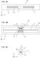
- Figs. 1A to 1C are views illustrating schematic configurations of a vibration body 1 of the vibration actuator.
- Fig. 1A is a plan view of the vibration body 1
- Fig. 1B is a front view of the vibration body 1
- Fig. 1C is a side view of the vibration body 1.
- an orthogonal coordinate system having an x-axis (x-direction), a y-axis (y-direction), and a z-axis (z-direction) is set for the vibration body 1.
- the z-direction is the thickness direction of the vibration body 1 and is a protruding direction of projecting portions 2a (described below in detail) that are provided at two positions.
- the y-direction is the longitudinal direction of the vibration body 1 and is a direction connecting the two projecting portions 2a.
- the x-direction is the transversal direction (width direction) of the vibration body 1 and is a direction perpendicular to the y-direction and the z-direction.
- a direction from the start point toward the end point of an arrow indicating the direction is defined as a positive direction (+direction)
- a direction from the end point toward the start point is defined as a negative direction (-direction).
- the vibration body 1 includes an elastic body 2 and an electric-mechanical energy conversion element 3 joined to the elastic body 2.
- the electric-mechanical energy conversion element 3 is, for example, a piezoelectric element that converts a voltage to a force by using an inverse piezoelectric effect, and electrodes to which a predetermined voltage is applied are provided on the front and back surfaces of rectangular thin-plate-shaped piezoelectric ceramics.
- the elastic body 2 includes the projecting portions 2a, suspending support portions 2b, support end portions 2c, and a base portion 2d.
- the base portion 2d has a rectangular flat-plate-like shape, and the electric-mechanical energy conversion element 3 is joined to the base portion 2d.
- the two projecting portions 2a are provided on the base portion 2d so as to protrude in the +z-direction from a surface opposite to a surface to which the electric-mechanical energy conversion element 3 is joined.
- the projecting portions 2a may be formed by press working the elastic body 2 (the base portion 2d) or by joining projecting members to the base portion 2d by using a predetermined method.
- the suspending support portions 2b are rectangular flat-plate-shaped portions that are provided at both ends of the base portion 2d in the y-direction and that serve to connect the base portion 2d and the support end portions 2c.
- the support end portions 2c are rectangular flat-plate-shaped portions for fixing the vibration body 1 to a holding portion 8 described below.
- Fig. 2C is a cross-sectional view illustrating a schematic structure of the projecting portion 2a.
- a friction material 2f is provided on a surface of a parent material 2e of the projecting portion 2a.
- the material of the parent material 2e is the same as that of the base portion 2d.
- martensitic stainless steel it is possible to use electroless nickel plating, chrome plating, a quench-hardened layer, a nitride film formed by ion nitriding treatment, or the like as the friction material 2f.
- parent material 2e By using a fiber-reinforced engineering plastic such as PEEK-CF30 or hard ceramics as the parent material 2e, it is also possible to use a configuration such that the parent material 2e serves also as the friction material 2f (in this case, there is no distinction between the parent material 2e and the friction material 2f).
- a fiber-reinforced engineering plastic such as PEEK-CF30 or hard ceramics
- the parent material 2e serves also as the friction material 2f (in this case, there is no distinction between the parent material 2e and the friction material 2f).
- FIG. 2A is a view for describing a first vibration mode
- Fig. 2B is a view for describing a second vibration mode.
- deformation of the vibration body 1 is illustrated with exaggeration.
- a contact body 4 that contacts the vibration body 1 and receives thrust (frictional driving force) from the vibration body 1 is illustrated.
- the contact body 4 is a member that contacts the projecting portions 2a of the vibration body 1. Due to vibration generated in the vibration body 1, the vibration body 1 and the contact body 4 move relative to each other in the y-direction as described below. Contact between the vibration body 1 and the contact body 4 is not limited to direct contact such that another member is not interposed between the vibration body 1 and the contact body 4. As long as the vibration body 1 and the contact body 4 move relative to each other due to vibration generated in the vibration body 1, contact between the vibration body 1 and the contact body 4 may be indirect contact such that another member is interposed between the vibration body 1 and the contact body 4.
- the first vibration mode illustrated in Fig. 2A is a secondary out-of-plane bending vibration mode in which three nodal lines that are substantially parallel to the x-direction are generated in the base portion 2d. Due to the first vibration mode, vibrations that become displaced in the y-direction are generated at end portions of the two projecting portions 2a.
- the second vibration mode illustrated in Fig. 2B is a primary out-of-plane bending vibration mode in which two nodal lines that are substantially parallel to the y direction are generated in the base portion 2d. Due to the second vibration mode, vibrations that become displaced in the z-direction are generated at the end portions of the two projecting portions 2a.
- a static frictional force between the projecting portions 2a and the contact body 4 serves as a holding force for maintaining the relative positions of the vibration body 1 and the contact body 4.
- adjusting the amplitude of vibration generated in the vibration body 1 by adjusting a voltage applied to the electric-mechanical energy conversion element 3 it is possible to adjust the contact time between the projecting portions 2a and the contact body 4 to change apparent frictional force.
- generating only vibration in the second vibration mode in the vibration body 1 and controlling the amplitude of the vibration it is possible to change a frictional force generated between the projecting portions 2a and the contact body 4.
- the end portions of the two projecting portions 2a contact the contact body 4.
- a friction material 4a is provided on a surface the contact body 4 that is a contact surface (frictional sliding surface) that contacts the projecting portions 2a.
- the friction material 2f is provided on the surface of the projecting portions 2a.
- the material of the friction material 4a and a method of forming the friction material 4a may be similar to those of the friction material 2f.
- Examples of the material of the elastic body 2 of the vibration body 1 include martensitic stainless steel whose vibration loss is small and high-toughness ceramics such as partially-stabilized zirconia (PSZ).
- Other examples the material include engineering plastics (FRP) such as polyether ether ketone (PEEK-CF30) reinforced by carbon fiber of about 30 wt%, semiconductors such as silicon carbide (SiC), and aluminum alloys.
- FRP engineering plastics
- PEEK-CF30 polyether ether ketone
- SiC silicon carbide
- Examples of the material of the electric-mechanical energy conversion element 3 of the vibration body 1 include piezoelectric ceramics such as lead zirconate titanate (PZT).
- Examples of the material of the contact body 4 include martensitic stainless steel, aluminum alloys, FRP such as PEEK-CF30, and fine ceramics such as PSZ or alumina (aluminum oxide).
- the materials of the vibration body 1 and the contact body 4 are not limited to those listed here.
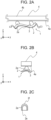
- Figs. 3A to 3D are views for describing the vibration actuator according to the first embodiment, and schematically illustrate the vibration body 1 and the contact body 4.
- Fig. 3A is a front view of the contact body 4 and one vibration body 1 pressed against (in pressed contact with) the contact body 4.
- an x-direction, a y-direction, and a z-direction are set as illustrated in Figs. 3A to 3D .
- the y-direction is defined as the left-right direction of the vibration actuator
- the +y side is defined as the right side
- the -y side is defined as the left side
- the z-direction is the up-down direction of the vibration actuator
- the +z side is defined as the upper side
- the -z side is defined as the lower side.
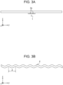
- Fig. 3B is a front view of the contact body 4, illustrating, with exaggeration, the vibration form of an out-of-plane bending mode generated in the contact body 4.
- a natural vibration mode is excited in the contact body 4 if the drive frequency is close to the natural frequency of the natural vibration mode of the contact body 4.
- an out-of-plane vibration mode that vibrates in the z-direction at a wavelength ⁇ with respect to a plane parallel to the xy-plane as illustrated in Fig.
- the projections 2a of the vibration body 1 and the contact body 4 intermittently repeat a contact state and a non-contact state.
- contact between the projections 2a and the contact body 4 becomes unstable, and, in addition, beating noise is generated and thrust decreases.
- the difference between a drive frequency exited in the vibration body 1 and the natural frequency of the natural vibration mode of the contact body 4 generates noise, and thrust may decrease.
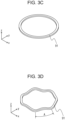
- Fig. 3D is a perspective view of the contact body 91 in which an out-of-plane bending mode generated in the contact body 91 is illustrated with exaggeration. Also in this case, when vibration is exited in the vibration body 1, a natural vibration mode is excited in the contact body 91 if the drive frequency of the vibration is close to the natural frequency of the natural vibration mode of the contact body 91.
- the excited out-of-plane vibration forms a progressive wave to become an amplified unnecessary vibration, and causes decrease in performance due to similar unnecessary vibration.
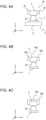
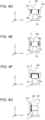
- Figs. 4A to 4G are right-side views for describing examples of a contact body unit and the vibration body 1 pressed against the contact body unit.
- Figs. 5A to 5C are bottom views illustrating schematic configurations of some of the contact body units illustrated in Figs. 4A to 4G .
- Fig. 4A is a view illustrating the basic configuration of a contact body unit according to the first embodiment, which is a configuration such that one vibration body 1 is pressed against the contact body 4 of a contact body unit 24.
- the contact body unit 24 is configured by joining a vibration-damping member 25 to a predetermined surface of the contact body 4 that is different from the contact surface, which is both side surfaces of the contact body 4 in the x-direction here.
- the vibration-damping member 25 is provided on both of the side surfaces of the contact body 4 in the x-direction that are connected to the contact surface and face each other.
- each of the vibration-damping members 25 is configured to be located above a lower end of the contact body 4, that is, the contact surface in the z-direction.
- the vibration-damping member 25 is constituted by a viscoelastic body or by a combination of a viscoelastic body and a reinforcement member.
- Figs. 4B to 4G are views for describing exemplary configurations of the vibration-damping member, illustrating configurations such that one vibration body 1 is pressed against the contact body 4 of the contact body unit.
- Fig. 4B is a view illustrating a contact body unit 24a, which is an example in which the vibration-damping member includes only a viscoelastic body 26a.
- Fig. 5A is a bottom view of the contact body unit 24a.
- the viscoelastic body 26a is joined to both side surfaces of the contact body 4 in the x-direction. It is assumed that the mechanical quality factor Q of the viscoelastic body 26a is lower than that of the contact body 4.
- a material having both of viscosity and elasticity such as rubber or resin is suitable.
- butadiene rubber, butyl rubber, silicon rubber, or the like having high vibration-damping performance is suitable.
- internal strain is generated in the viscoelastic body 26a in accordance with strain of the joining surface generated in accordance with deformation of the contact body 4 in a natural vibration mode excited in the contact body 4 as unnecessary vibration.
- Fig. 4C is a view illustrating a contact body unit 24b, which is an example in which the vibration-damping member includes only a viscoelastic body 26b that is joined also to a back surface of the contact body 4, which is a surface opposite to the contact surface.
- a bottom view which is similar to Fig. 5A , is omitted.
- the viscoelastic body 26b is joined to three surfaces (both side surfaces in the x-direction and the back surface) of the contact body 4 by fitting the contact body 4 into a groove portion in the viscoelastic body 26b having a recessed cross-sectional shape.
- rubber or resin is suitable as the material the viscoelastic body 26b.
- the contact body unit 24b may be configured by using a resin material having a large attenuation coefficient and by fitting the contact body 4 and viscoelastic body to each other.
- a resin material having a large attenuation coefficient By joining the viscoelastic body 26b to the three surfaces of the contact body 4, it is possible to increase region for absorbing vibration energy in accordance with strain generated in accordance with deformation of the contact body 4 and to increase the effect of suppressing unnecessary vibration compared with the contact body unit 24a.
- Fig. 4D is a view illustrating a contact body unit 24c, which is an example in which the vibration-damping member includes a combination of a viscoelastic body 26c and a reinforcement member 27a.
- Fig. 5B is a bottom view of the contact body unit 24c.
- the viscoelastic body 26c is joined to both side surfaces of the contact body 4 in the x-direction, and the reinforcement member 27a is joined to the viscoelastic body 26c. In this way, the viscoelastic body 26c is interposed between the contact body 4 and the reinforcement member 27a.
- rubber or resin is suitable as the material of the viscoelastic body 26c, and a double-sided tape or an adhesive may be used additionally. It is assumed that the mechanical quality factor Q of the viscoelastic body 26c is lower than that of each of the contact body 4 and the reinforcement member 27a.
- a material whose elastic modulus is sufficiently higher than that of the viscoelastic body 26c is suitable. For example, various metals, ceramics, engineering plastic, and the like are usable, and the material may be the same as that of the contact body 4.
- both side surfaces of the viscoelastic body 26c are joined to the contact body 4 and the reinforcement member 27a. Since the displacement distribution of the viscoelastic body 26c is restrained at the joint surface with the reinforcement member 27a having a larger elastic modulus, it is possible to absorb vibration energy by generating shearing strain of the viscoelastic body 26c due to deformation of the contact body 4 and to reduce the vibration amplitude of unnecessary vibration generated in the contact body 4.
- Fig. 4E is a view illustrating a contact body unit 24d, which is an example in which the vibration-damping member has a multilayer structure in which a plurality of viscoelastic bodies 26d and a plurality of reinforcement members 27b are alternately arranged.
- Fig. 5C is a bottom view of the contact body unit 24d.
- a viscoelastic body 26d and a reinforcement member 27b are joined from both sides of the contact body 4 in the x-direction and another set of a viscoelastic body 26d and a reinforcement member 27b are further joined.
- the materials of the viscoelastic body 26d and the reinforcement member 27b are similar to those described with reference to Fig. 4D .
- the vibration-damping member has a multilayer structure in which the plurality of the viscoelastic bodies 26d and the plurality of the reinforcement members 27b are alternately arranged, it is possible to increase vibration energy to be absorbed by generating shearing strain. Thus, it is possible to more effectively reduce the vibration amplitude of unnecessary vibration generated in the contact body 4. Moreover, compared a case of the contact body unit 24c, it is possible to reduce the thickness of the viscoelastic body 26d in the x-direction. By reducing the thickness of the viscoelastic body 26d, it is possible to reduce displacement of the vibration-damping member in the xy-plane when an external force is applied to the contact body unit 24d via the reinforcement member 27b.
- a linear guide that linearly guides the contact body unit 24d is configured by supporting the reinforcement member 27b that is exposed on a side surface, it is possible to improve the rigidity of the linear guide, compared with a case of the contact body unit 24c. Thus, it is possible to position the contact body 4 with high precision.
- Fig. 4F is a view illustrating a contact body unit 24e, which is an example in which the vibration-damping member includes a combination of a viscoelastic body 26e and a reinforcement member 27c and is joined also to the back surface of the contact body 4.
- a bottom view which is similar to Fig. 5B , is omitted.
- the viscoelastic body 26e is joined to three surfaces (both side surfaces in the x-direction and the back surface) of the contact body 4 by fitting the contact body 4 into a groove portion of the viscoelastic body 26e having a recessed cross-sectional shape.
- the reinforcement member 27c is joined to three surfaces (both side surfaces in the x-direction and the back surface) of the viscoelastic body 26e by fitting the viscoelastic body 26e into a groove portion of the reinforcement member 27c having a recessed cross-sectional shape. That is, this is an example of a combination of the configuration of the contact body unit 24b illustrated in Fig. 4C and the configuration of the contact body unit 24c illustrated in Fig. 4D .
- the materials of the viscoelastic body 26e and the reinforcement member 27c are similar to those described with reference to Fig. 4D .
- Advantageous effects due to this configuration are also similar to those described with reference to Fig. 4C and Fig. 4D .
- Fig. 4G is a view illustrating a contact body unit 24f, which is an example in which the vibration-damping member includes a combination of a viscoelastic body 26f and a reinforcement member 27d.
- the viscoelastic body 26f is joined to one side surface of the contact body 4 in the x-direction (the left side surface in the illustrated example), and the reinforcement member 27d is joined to the viscoelastic body 26f.
- an adhesive is used as the viscoelastic body 26f, and due to the wettability of the adhesive, the viscoelastic body 26f spreads to two flat surfaces (the contact surface and the back surface) of the contact body 4 that are parallel to the xy-plane.
- the amount of the adhesive to become the viscoelastic body 26f is controlled so that the adhesive may not contact the projection 2a of the vibration body 1.
- the reinforcement member 27d has a length in the z-direction that exceeds the thickness of the contact body 4 so as to receive the adhesive. In this way, end portions of the vibration-damping member (end portions of the viscoelastic body 26f, end portions of the reinforcement member 27d) protrude further than the contact surface and the back surface.
- the material of the reinforcement member 27d is similar to that described regarding the contact body unit 24c with reference to Fig. 4D .
- the contact body unit 24f it is possible to obtain the advantageous effect of suppressing unnecessary vibration by absorbing excitation energy by using shearing strain of the viscoelastic body 26f. Since the viscoelastic body 26f spreads to two flat surfaces of the contact body parallel to the xy-plane, the adhesive strength of the reinforcement member 27d is increased, and absorption of excitation energy is performed as internal strain is generated in the viscoelastic body that has spread. Thus, it is possible to reduce the vibration amplitude of unnecessary vibration generated in the contact body 4.
- various contact body units and vibration-damping members (viscoelastic bodies, reinforcement members) described with reference to Figs. 4A to 4G may be referred to as the contact body unit 24, the vibration-damping member 25, the viscoelastic body 26, and the reinforcement member 27 by using representative numerals. It is also possible to provide the vibration-damping member 25 with a function other than suppression of unnecessary vibration.
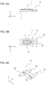
- FIGs. 6A, 6B, and 6C are respectively a plan view, a front view, and a right-side view illustrating the positional relationship between a contact body unit 24g and a detector 83.
- the viscoelastic body 26c is joined to both side surfaces of the contact body 4 in the x-direction
- the reinforcement member 27a is joined to the viscoelastic body 26c
- a part of the reinforcement member 27a is replaced with a scale 27e.
- the scale 27e is a reflective diffraction grating and has a pattern of reflective portions and non-reflective portions formed by removing a metal film, deposited on a glass surface, by etching or laser processing.
- the scale 27e is joined to the viscoelastic body 26c, and thus constrains a side surface of the viscoelastic body 26c and functions as a reinforcement member. In this way, a part of the vibration-damping member 25 constitutes the scale 27e.
- the detector 83 is set at a position that is separated by a gap from the scale 27e in the x-direction and that does not physically interfere with the scale 27e.
- the detector 83 includes a light source and a light receiver, and can read the scale 27e by emitting light from the light source to the scale 27e and receiving reflection of the light with the light receiver.
- the detector 83 and the scale 27e constitute a displacement-detecting portion 28 and functions as a linear encoder that detects displacement in the y-direction.
- the scale 27e can have the effects and the functions of both of the vibration-damping member 25 and the displacement-detecting portion 28.
- the viscoelastic body 26c serves as a vibration insulator that makes it difficult for vibration of the contact body 4 to be transmitted the scale 27e, and thus it is possible to reduce displacement detection error due to vibration of the scale 27e.
- the scale 27e in the z-direction is illustrated to be less than that of the contact body 4 in Figs. 6A to 6C , as described above with reference to Fig. 4G , the scale 27e may be configured to overhang toward the contact surface side of the contact body 4. When the scale 27e overhangs, the area of the viscoelastic body 26 is increased, and it is possible to further increase the vibration-damping effect. As described below with reference to Fig.
- the scale 27e and the reinforcement member 27a are illustrated as independent bodies in Figs. 6A to 6C , a film-shaped scale may be affixed to a side surface of the reinforcement member. It may be possible to form a scale by performing vapor deposition or printing on a side surface of the viscoelastic body. Although an exemplary configuration such that a scale is affixed to a side surface of the contact body via a viscoelastic body has been described above, this is not a limitation.
- the contact body may be formed from a metal, protruding/recessed shapes may be formed on a side surface of the contact body by etching or electroforming, and a viscoelastic body may be injected into recessed portions.
- a shape such that the viscoelastic body is disposed in the recessed portion is periodically repeated in the y-direction, the protruding portions serve as reflective portions and the viscoelastic body injected into the recessed portions serve as non-reflective portions.
- a function equivalent to that of a scale is realized, and it can be expected that the injected viscoelastic body suppresses unnecessary vibration in the same way as described above.
- the contact body units 24 described with reference to Figs. 4A to 6C are examples in which the vibration-damping member 25 is joined to the contact body 4 over the entire area in the y-direction.
- this is not a limitation, and the vibration-damping member 25 may be joined to the contact body 4 in a part in the y-direction.
- providing the vibration-damping member 25 over the entire area in the y-direction is effective in suppression of unnecessary vibration
- providing the vibration-damping member 25 in a part in the y-direction makes it possible to achieve reduction in size, weight, and space, prevention of interference with other components, cost reduction, and the like.
- a first criterion is that the sum total of the length of the vibration-damping member 25 in the y-direction is greater than or equal to 1/2 of the wavelength of a natural vibration mode excited in the contact body 4 (greater than or equal to 1/2 ⁇ in Figs. 3A to 3D ).
- a second criterion is that the sum total of the length of the vibration-damping member 25 in the y-direction is greater than or equal to the length of the interval between adjacent nodal lines of a vibration mode excited in the vibration body 1.
- a third criterion is that the sum total of the length of the vibration-damping member 25 in the y-direction is greater than or equal to the center-to-center distance between the projections 2a of the elastic body 2.
- a fourth criterion is that the vibration-damping member 25 is provided at a position including an antinode of a natural vibration mode excited in the contact body 4.
- the vibration-damping member 25 on a side surface of the contact body 4, it is possible to suppress unnecessary vibration generated in the vibration actuator and to prevent output power (thrust) per volume or per weight from becoming small.
- the width of the contact body unit 24 in the x-direction is illustrated to be greater than the width of the vibration body 1 and less than the width of the holding portion 8 in Figs. 4A to 4G , this is not a limitation.
- the shape and the material of the viscoelastic body 26 and the reinforcement member 27 of the vibration-damping member 25 it is also possible to further reduce the width dimension of the contact body unit 24 and to set the width dimension to be, for example, less than the width dimension of the vibration body 1. In this way, it is possible to reduce the size of the vibration actuator.
- the present invention is effective for another natural vibration mode such as an in-plane vibration mode, a torsional vibration mode, or the like. Also for vibration such as in-plane vibration and torsional vibration, it is possible to suppress the vibration in the same way as for out-of-plane vibration by providing the vibration-damping member 25 so as to include an antinode with large strain.
- vibration-damping member 25 by appropriately changing the disposition of the vibration-damping member 25 and the configuration of the vibration-damping member 25, it is possible to suppress unnecessary vibration due to any vibration mode, for a plurality of vibration modes whose positions of portions (antinodes) where strain of the vibration mode is large differ.
- the viscoelastic body 26 does not cover an end portion of the contact body 4 including a surface parallel to the xz-plane. Even when the viscoelastic body 26 covers the end portion of the contact body 4, the effect of suppressing unnecessary vibration is not likely to decrease, and such a configuration is not beyond the scope of the present invention. However, since only a small effect of suppressing unnecessary vibration is obtained by covering a surface parallel to the xz-plane where strain is not generated with respect to unnecessary vibration of the contact body 4, examples in each of which the vibration-damping member is joined to a side surface of the contact body 4 have been described in the present embodiment.
- the contact surface of the contact body 4 is to be protruded with respect to the vibration-damping member 25 or the vibration-damping member 25 is to be provided at a position of an antinode of a specific natural vibration mode, it is necessary to assemble the contact body unit 24 after determining the relative positions of the contact body 4 and the vibration-damping member 25 with high precision. In such a case, it is possible to efficiently assemble the contact body unit 24 by providing the vibration-damping member 25 and the contact body 4 with a positioning structure such as a positioning pin, a parallel key, any other protruding/recessed shape or mark, or the like.
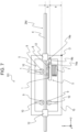
- Fig. 7 is a front view illustrating a schematic configuration of a vibration actuator 101 according to the first embodiment.
- Figs. 8A to 8C are views for describing configurations of a vibration body unit 5 of the vibration actuator 101 according to the first embodiment.
- the vibration actuator 101 includes one vibration body unit 5 and the contact body 4 that contacts the vibration body 1 of the vibration body unit 5.
- the contact body unit 24d described above (referred to as the contact body 4 in the following description) is used in order to suppress unnecessary vibration generated in the contact body 4.
- Various components of the vibration actuator 101 are assembled on a support member 15 that is a base member.
- the vibration body unit 5 includes the vibration body 1, a nonwoven cloth 16, a pressing portion 7, the holding portion 8, a reaction-force receiving portion 9, and a rotation support portion 10.
- the vibration body unit 5 has a pressing support structure that can excite vibration in the vibration mode described with reference to Figs. 2A to 2C .
- the support end portions 2c of the elastic body 2 are fixed to an upper surface of a wall portion on the y-direction side, which is a side wall of the holding portion 8.
- the nonwoven cloth 16 is disposed on the back surface side (a surface opposite to a surface joined to the elastic body 2) of the electric-mechanical energy conversion element 3.
- the nonwoven cloth 16 is a cloth-like member made of a nonwoven cloth material such as wool felt, glass wool, or the like, and supports the vibration body 1 while maintaining a vibration mode generated in the vibration body 1.
- the pressing portion 7 presses the vibration body 1 against the contact body 4 via the nonwoven cloth 16, the projecting portions 2a of the vibration body 1 contact the contact body 4.
- the vibration body 1 is fixed to the holding portion 8, and the holding portion 8, integrated with the vibration body 1, is pressed toward the contact body 4.
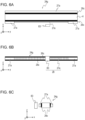
- Fig. 8A is a front view of a main part of the vibration body unit 5
- Fig. 8B is a bottom view corresponding to Fig. 8A .
- a through-hole 8e extending therethrough in the z-direction is provided, and the electric-mechanical energy conversion element 3 is in a state of being exposed from the through-hole 8e when the holding portion 8 is seen from the -z-direction side in a state in which the vibration body 1 is held by the holding portion 8.
- the nonwoven cloth 16 (the hatched region in Fig. 8B ) is set inside of the through-hole 8e so as to be in contact with the electric-mechanical energy conversion element 3.
- a flexible wiring board (not shown) for supplying electric power to the electric-mechanical energy conversion element 3 is attached to the back surface (surface on the -z-direction side) of the electric-mechanical energy conversion element 3.
- the nonwoven cloth 16 is set so as to be in contact with the flexible wiring board attached to the electric-mechanical energy conversion element 3.
- the pressing portion 7 presses the projecting portions 2a of the vibration body 1 against the contact body 4 via the nonwoven cloth 16 with a predetermined pressing force.
- the pressing portion 7 includes an elastic component having an elastic force such as a coil spring, a plate spring, a coned disc spring, a wave washer, rubber, an air tube, or the like that exhibits a restoring force in the z-direction. It is also possible to configure a pressing portion that uses a magnetic force instead of an elastic force, and a magnet or the like can be used in this case. In the present embodiment, a compression coil spring is used as the pressing portion 7.
- the reaction-force receiving portion 9 is disposed so as to contact the back surface (a surface opposite to the contact surface) of the contact body 4, and receives a reaction force of a pressing force that presses the projecting portions 2a of the vibration body 1 against the contact body 4.
- Two reaction-force receiving portions 9 that face each other are provided in the negative y-axis direction with respect to the vibration body unit 5, and thus three reaction-force receiving portions 9 and one vibration body unit 5 support the contact body 4 in the z-direction.
- each of the reaction-force receiving portions 9 includes a roller that is supported by the rotation support portion 10, which is attached to the support member 15, so as to be rotatable around an axis parallel to the x-axis.
- the support member 15 is fixed a frame or the like of an apparatus in which the vibration actuator 101 is mounted, and that the contact body 4 moves in the y-direction relative to the support member 15 (the vibration body unit 5) whose position does not change in the apparatus.
- the contact body 4 is supported by the support member 15 in a state of being movable in the y-direction due to thrust that the contact body 4 receives from the vibration body 1 included in the vibration body unit 5.
- the support member 15 four rollers that are rotatable around axes parallel to z-axis are provided as contact-body support portions 12 that movably support the contact body 4.
- the four contact-body support portions 12 function as a linear guide that allows the contact body 4 to move in the y-direction in a state in which the degree of freedom of the contact body 4 in the x-direction is constrained.
- Fig. 8C is a perspective view illustrating a schematic configuration of the coupling portion 14.
- the coupling portion 14 includes a link member 14b (linking portion) in which two holes are formed at a predetermined interval so as to extend therethrough in the x-direction and cylindrical pins 14a (shaft) that are respectively inserted into the two holes of the link member 14b and substantially parallelly attached to the link member 14b.
- Two pins 14a are fixed to the link member 14b in the respective holes of the link member 14b.
- the two pins 14a and the link member 14b may be integrally (seamlessly) formed in an H-shape as seen from the z-direction.
- One of the two pins 14a is positioned at a position that is separated by a distance a in the +z-direction from a reference origin O of the support member 15 illustrated in Figs. 4A to 4G , and thus the coupling portion 14 has a degree of rotational freedom around a central axis of the pin 14a positioned with respect to the support member 15.
- the center of the contact body 4 is positioned at a position that is separated by a distance b in the +z-direction from the center of the pin 14a positioned with respect to the support member 15.
- the contact body 4 is positioned, with high precision, at a position that is separated by a distance a + b from the reference origin O of the support member 15 in the +z-direction.
- the vibration body unit 5 it is possible for the vibration body unit 5 to slide in the z-direction, and it is possible to press the vibration body unit 5 against the contact body 4 as the vibration body unit 5 conforms to the shape of the contact body 4 even if the contact body 4 has a shape having undulation in the yz-plane due to a manufacturing error or the like.
- Figs. 9A to 9C are views illustrating schematic configurations of another vibration actuator 102 according to the first embodiment.
- Fig. 9A is a plan view of the vibration actuator 102
- Fig. 9B is a front view of the vibration actuator 102.
- the vibration actuator 102 includes one vibration body unit 11 and the contact body 4 that contacts the vibration body 1 of the vibration body unit 11, the contact body 4 is fixed to the support member 15, and the vibration body 1 performs relative movement.
- the contact body unit 24d described above (referred to as the contact body 4 in the following description) is used in order to suppress unnecessary vibration generated in the contact body 4.
- Constituent elements of the vibration actuator 102 that correspond to those of the vibration actuator 101 (see Fig. 7 ) will be denoted by the same names and numerals, and descriptions of common configurations and functions will be omitted.
- the vibration body unit 11 includes a holding portion 18 in which the holding portion 8, a pressing portion 13, the reaction-force receiving portion 9, and the rotation support portion 10 are integrated as a unit.
- a spacer 19 to which the nonwoven cloth 16 is affixed is disposed inside of the holding portion 18.
- the support end portions 2c at ends of the vibration body 1 in the y-direction are fixed to the holding portion 18.
- Fig. 9C is a right-side view illustrating a schematic configuration for describing the supporting relationship between the vibration body unit 11 and the contact body 4.
- An opening 18a is formed in the holding portion 18.
- the dimension of the opening 18a in the x-direction is set to be greater than the width dimension of the contact body 4 in the x-direction, and, since an appropriate gap is provided, the opening 18a functions as a linear guide that allows the vibration body unit 11 to move in the y-direction.
- the reaction-force receiving portion 9 is provided opposite to the contact surface between the contact body 4 and the projecting portions 2a (above (on the +z side of) the contact body 4), and receives a reaction force of a force that presses the vibration body 1 (the projecting portions 2a) against the contact body 4.
- the reaction-force receiving portion 9 is supported by a rotation support portion 10 (not shown) equivalent to the rotation support portion 10 of the vibration actuator 101 so as to be rotatable around an axis parallel to the x-axis, and a compression coil spring is disposed as the pressing portion 13 for the rotation support portion 10.
- the reaction-force receiving portion 9 is pressed against the contact body 4 and the end portions of the two projecting portions 2a of the vibration body 1 are pressed against the contact body 4.
- the vibration actuator 102 With the vibration actuator 102, it is possible for the vibration body unit 11 to move in the y-direction.
- an opening 15a in the support member 15 As illustrated in Fig. 9A , it is possible to expose the upper surface of the vibration body unit 11 to the outside, and it is possible to connect an object to be driven to the upper surface.
- vibration-damping member 25 that is an independent body is joined to a side surface of the contact body 4
- this is not a limitation.
- Exemplary configurations for providing the contact body with a vibration-damping member include the following examples.
- a vibration-damping member by dipping, which is a coating method in which a contact body is immersed in a liquid rubber or a liquid resin.
- dipping for portions (for example, the contact surface and the like) where some inconvenience occurs if the viscoelastic body adheres, it is possible to avoid covering with the viscoelastic locally by providing a mask on the contact body beforehand and removing the mask after the dipping process.
- vibration-damping member by insert molding, which is a method of performing integral molding by setting the contact body and the reinforcement member in a die and injecting a resin material that has been heated and melted into a space between the contact body and the reinforcement member.
- the contact body and the viscoelastic body by double molding.
- PEEK polyetheretherketone
- carbon fiber carbon fiber
- an elastomer may be used as the viscoelastic body as secondary forming.
- These configurations can not only increase mass-productivity and allow the viscoelastic body to be configured at low cost but also provide an effect of increasing cohesion between the viscoelastic body and the contact body to prevent removal and positional displacement of the viscoelastic body.
- the viscoelastic body is to be formed by using a die, it is possible to determine the relative positions of the contact body and the reinforcement member with high precision and to configure a viscoelastic body having a complex shape.
- the contact body 4 has a linear shape having the y-direction as the longitudinal direction
- this is not a limitation. It is possible for the contact body to have any curved shape, and, it is possible to suppress unnecessary vibration by providing a vibration-damping member also in a curved contact body. Also when a curved contact body is used, it is possible to fix the vibration body and to cause the contact body to be on the driven side. At this time, it is preferable to configure a contact-body support portion having a shape conforming with the shape of the contact body. Conversely, it is also possible to fix the contact body and to cause the vibration body to be on the driven side, and, in this case, the vibration body unit performs relative movement along the curved contact body.
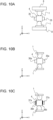
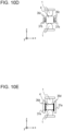
- Figs. 10A to 10E are right-side views illustrating examples of a contact body unit and the vibration body 1 pressed against the contact body unit.
- Fig. 10A is a view illustrating the basic configuration of the contact body unit according to the second embodiment, which is a configuration such that two vibration bodies 1 facing each other are pressed against the contact body 4 of a contact body unit 34. That is, the contact body 4 has contact surfaces on the upper and lower sides (in the positive z-direction and the negative z-direction) thereof.
- the contact body unit 34 is configured by joining a vibration-damping member 35 to both side surfaces of the contact body 4 in the x-direction.
- An upper end and a lower end of the vibration-damping member 35 are respectively configured to be located below and above an upper end and a lower end of the contact body 4 in the z-direction.
- the vibration-damping member 35 is constituted by a viscoelastic body or by a combination of a viscoelastic body and a reinforcement member.
- Figs. 10B to 10E are views for describing exemplary configurations of the vibration-damping member, illustrating configurations such that two vibration bodies 1 facing each other are pressed against the contact body 4 of the contact body unit.
- Fig. 10B is a view illustrating a contact body unit 34a, which is an example in which the vibration-damping member includes only a viscoelastic body 36a, as with the contact body unit 24a described with reference to Fig. 4B .
- the viscoelastic body 36a is joined to both side surfaces of the contact body 4 in the x-direction.
- the characteristics and the materials of the vibration-damping member and the mechanism for suppressing unnecessary vibration are similar to those of the contact body unit 24a, and descriptions thereof will be omitted here.
- Fig. 10C is a view illustrating a contact body unit 34b, which is an example in which the vibration-damping member includes a combination of a viscoelastic body 36b and a reinforcement member 37a, as with the contact body unit 24c described with reference to Fig. 4D .
- the viscoelastic body 36b is joined to both side surfaces of the contact body 4 in the x-direction, and the reinforcement member 37a is joined to the viscoelastic body 36b.
- the characteristics and the materials of the vibration-damping member and the mechanism for suppressing unnecessary vibration are similar to those of the contact body unit 24c, and descriptions thereof will be omitted here.
- Fig. 10D is a view illustrating a contact body unit 34c, which is an example in which the vibration-damping member has a multilayer structure in which a plurality of viscoelastic bodies 36c and a plurality of reinforcement members 37b are alternately arranged, as with the contact body unit 24e described with reference to Fig. 4E .
- a viscoelastic body 36c and a reinforcement member 37b are joined from both sides of the contact body 4 in the x-direction, and another set of a viscoelastic body 36c and a reinforcement member 37b are further joined.
- the characteristics and the materials of the vibration-damping member and the mechanism for suppressing unnecessary vibration are similar to those of the contact body unit 24e, and descriptions thereof will be omitted here.
- Fig. 10E is a view illustrating a contact body unit 34d, which is an example in which the vibration-damping member includes a combination of a viscoelastic body 36d using an adhesive and a reinforcement member 37e, as with the contact body unit 24f described with reference to Fig. 4G .
- the example illustrated in 4G is an example in which the vibration-damping member is provided on only one side surface of the contact body 4 in the x-direction, here, the vibration-damping member is provided on both side surfaces of the contact body 4 in the x-direction.
- the characteristics and the materials of the vibration-damping member and the mechanism for suppressing unnecessary vibration are similar to those of the contact body unit 24f, and descriptions thereof will be omitted here.
- contact body units and vibration-damping members (viscoelastic bodies, reinforcement members) described with reference to Figs. 10A to 10E may be referred to as the contact body unit 34, the vibration-damping member 35, the viscoelastic body 36, and the reinforcement member 37 by using representative numerals.
- the vibration-damping member 35 on a side surface of the contact body 4, it is possible to suppress unnecessary vibration generated in the vibration actuator and to prevent output power (thrust) per volume or per weight from becoming small.
- Fig. 11 is a front view illustrating a schematic configuration of a vibration actuator 201 according to the second embodiment.
- the vibration actuator 201 includes two vibration body units 21 and the contact body 4 that contacts the vibration bodies 1 of the vibration body units 21.
- the contact body unit 34c described above (referred to as the contact body 4 in the following description) is used in order to suppress unnecessary vibration generated in the contact body 4.
- Various components of the vibration actuator 201 are assembled on the support member 15 that is a base member.
- Each vibration body unit 21 includes two vibration bodies 1, the nonwoven cloths 16, a pressing portion 17, and the holding portions 8.
- the vibration bodies 1 facing each other are pressed against the contact body 4 by hooking ends of the pressing portion 17 on hooks 8a provided on side surfaces of the holding portions 8.
- a tension spring is used as the pressing portion 17.
- each holding portion 8 is attached to the support member 15 via the coupling portion 14 to perform positioning of the contact body 4 in the z-direction, and the vibration bodies 1 and the holding portions 8 are slidable in the z-direction.
- This configuration is a configuration such that the three sets of reaction-force receiving portions 9 and rotation support portions 10 of the vibration actuators 101 are replaced with the vibration bodies 1 and the holding portions 8.
- the projections 2a of the vibration body 1 serve as the reaction-force receiving portions 9.
- the contact body 4 is supported by the support member 15 in a state of being movable in the y-direction due to thrust that the contact body 4 receives from the vibration body 1 included in each vibration body unit 21.
- the support member 15 four rollers that are rotatable around axes parallel to z-axis are provided as contact-body support portions 12 that movably support the contact body 4.
- the four contact-body support portions 12 function as a linear guide that allows the contact body 4 to move in the y-direction by constraining the degree of freedom of a side surface of the reinforcement member 37b in the xy-plane.
- the vibration actuator 201 having such a configuration, it is possible to reduce constituent elements such as the reaction-force receiving portion 9 and the rotation support portion 10 by supporting the contact body 4 in the z-direction by using four vibration bodies 1. Moreover, it is possible to increase the thrust of the vibration actuator 201 by using the vibration body unit 21 instead of the reaction-force receiving portion 9 and the rotation support portion 10. If the vibration body 1 used in the vibration actuator 101 and the vibration body 1 used in the vibration actuator 201 have the same performance, the vibration actuator 201 can obtain thrust that is four times larger than the thrust obtained by the vibration actuator 101. With the configuration of the contact body unit 34c described above, it is possible to increase the effect of suppressing unnecessary vibration generated in the contact body 4 and to prevent generation of noise and decrease of performance due to unnecessary vibration.
- the thickness of the viscoelastic body in the x-direction compared with the contact body units 34a and 34b.
- By reducing the thickness of the viscoelastic body it is possible to reduce displacement of the vibration-damping member in the xy-plane when an external force is applied to the contact body unit 34c via the reinforcement member 37b, and it is possible to increase rigidity as a linear guide.
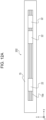
- Figs. 12A and 12B are views illustrating schematic configurations of another vibration actuator 202 according to the second embodiment.
- Fig. 12A is a plan view of the vibration actuator 202
- Fig. 12B is a front view of the vibration actuator 202.
- the vibration actuator 202 includes three vibration body units 22 and the contact body 4 that contacts the vibration bodies 1 of the vibration body units 22, the contact body 4 is fixed to the support member 15, and the vibration bodies 1 perform relative movement.
- the contact body unit 34c described above (referred to as the contact body 4 in the following description) is used in order to suppress unnecessary vibration generated in the contact body 4.
- Constituent elements of the vibration actuator 202 that correspond to those of the vibration actuator 201 (see Fig. 11 ) will be denoted by the same names and numerals, and descriptions of common configurations and functions will be omitted.
- the vibration body unit 22 is a unit such that the reaction-force receiving portion 9 and the rotation support portion 10 of the vibration body unit 11 used in the vibration actuator 102 are replaced with the vibration body 1 and the spacer 19.
- the vibration bodies 1 facing each other are pressed against the contact body 4 by hooking ends of the pressing portion 17 on hooks 19a provided on the spacer 19.
- the two vibration bodies 1 are supported by the holding portions 18 to be slidable in the z-direction, and the degree of freedom other than that in the z-direction is constrained with respect to the holding portions 18.
- the opening 18a is provided in the holding portion 18 and functions as a linear guide that allows the vibration body unit 22 to move in the y-direction.
- the vibration body unit 22 on the left side can be driven in the y-direction.
- the vibration body units 22 at the center and at the right end are coupled to each other by the coupling portion 14 via the holding portion 18 to be slidable relative to each other in the z-direction.
- the coupling portion 14 be provided to be offset in the x-direction so as not to interfere with the contact body 4. It is possible to drive the vibration body unit group 23, which is constituted by the two coupled vibration body units 22, together in the y-direction.
- the vibration actuator 202 it is possible for the left vibration body unit 22 and the vibration body unit group 23 to move independently in the y-direction.
- By providing an opening 15b in the support member 15 as illustrated in Fig. 12A it is possible to expose the upper surfaces of the left vibration body unit 22 and the vibration body unit group 23 to the outside, and it is possible to connect an object to be driven to the upper surfaces.
- the vibration actuator 202 configured as described above, it is possible to independently drive the plurality of vibration body units 22 or the vibration body unit group 23 via one contact body 4. At this time, by using the contact body unit 34c, it is possible to effectively suppress unnecessary vibration excited in the contact body. Moreover, since the two vibration body units 22 are coupled to constitute the vibration body unit group 23, it is possible for the vibration body unit group 23 to generate thrust that is four times larger than that of the vibration body unit 11.
- each vibration body 1 conforms to the contact body 4 with respect to deformation of the contact body in the longitudinal direction (in the yz-plane), and thus it is possible to reduce variation in pressing reaction force applied to each vibration body 1. Thrust decreases in a vibration body 1 to which a relatively small pressing reaction force is applied, and a risk of wear due to overload or the like occurs in a vibration body 1 to which a relatively large pressing reaction force is applied.
- the vibration body unit group 23 it is possible to reduce variation in pressing reaction force and to efficiently generate thrust in each vibration body 1.
- Figs. 13A to 13F are right side views for describing examples of a contact body unit and the vibration bodies 1 pressed against the contact body unit.
- Fig. 13A illustrates a configuration such that two vibration bodies 1 facing each other support the contact body 4, which is a configuration similar to those described with reference to Figs. 10A to 10E .
- Fig. 13B illustrates a configuration such that a contact body 74b having a polygonal cross section is supported by disposing vibration bodies 1 on four side surfaces of the contact body 74b.
- Four vibration-damping members 75a are joined to the contact body 74b at positions displaced from the vibration bodies 1 to constitute a contact body unit having a rectangular cross section.
- the vibration-damping members 75a are similar to the vibration-damping members 25 and 35 described above.
- Fig. 13C illustrates a configuration such that a side surface (curved surface) of a contact body 74c having a substantially circular cross section is supported by three vibration bodies 1 that are arranged at substantially 120° interval in the zx-plane.
- Three fan-shaped vibration-damping members 75b are joined to the side surface of the contact body 74c to constitute a contact body unit having a circular cross section.
- the vibration-damping members 75b are similar to the vibration-damping members 25 and 35 described above.
- Fig. 13D illustrates a configuration such that a contact body 74d having a polygonal (here, hexagonal) cross section is supported by disposing vibration bodies 1 on three side surfaces that are not adjacent to each other, among the side surfaces of the contact body 74d.
- Three vibration-damping members 75c are joined to the other three side surfaces of the contact body 74d against which the vibration bodies 1 are not pressed.
- the vibration-damping members 75c are similar to the vibration-damping members 25 and 35 described above.
- Fig. 13E illustrates a configuration such that a side surface (curved surface) of a contact body 74e having a substantially circular cross section is supported by vibration bodies 1 and 81 whose size and thrust differ from each other.
- two fan-shaped vibration-damping members 75b are joined to the side surface of the contact body 74e to constitute a contact body unit having a circular cross section.
- Fig. 13F illustrates a configuration such that a side surface (curved surface) of the contact body 74e having a substantially circular cross section is supported by two vibration bodies 1 and two reaction-force receiving portions 9.
- two fan-shaped vibration-damping members 75b are joined to the side surface of the contact body 74e to constitute a contact body unit having a circular cross section.
- vibration bodies By appropriately combining these configurations, it is possible to appropriately support a contact body having any of various cross-sectional shapes by using vibration bodies. By providing vibration-damping members on the side surface of the contact body, it is possible to suppress unnecessary vibration generated in a vibration actuator and to prevent output power (thrust) per volume or per weight from becoming small.
- Fig. 14 is a front view illustrating a state in which a displacement-detecting portion 87 is attached to the vibration body unit 22.
- the vibration body unit 22 is described here, it is also possible to mount the displacement-detecting portion 87 on another vibration body unit.
- the displacement-detecting portion 87 includes a scale 82 and the detector 83.
- the scale 82 is attached to the contact-body support portion 12, which is provided on the holding portion 18, at a position that does not physically interfere with (does not contact) the contact body 4 (not shown in Fig. 14 ).
- the scale 82 rotates together with the contact-body support portion 12 in accordance with displacement of the contact body 4.
- the detector 83 detects the movement amount of the contact body 4 in the y-direction by reading the rotational displacement of the scale 82.
- the detector 83 includes a light source and a light receiver, and can read the rotational displacement of the scale 82 by emitting light from the light source to the scale 82 and receiving reflection of the light with the light receiver. Based on the movement amount of the contact body 4 in the y-direction output by the detector 83, it is possible to control drive parameters such as the position, the velocity, the acceleration, and the like of the contact body 4.
- the displacement-detecting portion 87 various types such as an optical type, a magnetic type, a capacitance type, and the like can be used. Although the displacement-detecting portion 87 described here is of a reflective optical type, a transmissive optical type can also be used. Moreover, instead of the displacement-detecting portion 87 of a rotational type, a linear displacement-detecting portion in which a linear scale is disposed on the contact body 4 and a detector is disposed in the vibration body unit may be used.
- a third embodiment will be described.
- an actuator unit in which a vibration actuator is unitized (packaged) by using an outer member will be described.
- Constituent elements of the vibration actuator that are similar to those of the first embodiment will be denoted by the same names and numerals, and descriptions of common configurations and functions will be omitted. It is assumed that the orthogonal coordinate system is similar to that in the first embodiment.
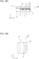
- Figs. 15A to 15D are views illustrating schematic configurations of an actuator unit 401 according to the third embodiment.
- Figs. 15A to 15D are respectively a plan view (top view), a side view, a front view, and a perspective view of the actuator unit 401.
- the actuator unit 401 is formed by unitizing the vibration actuator 201 by using an outer member 86.
- the support member 15 of the vibration actuator 201 is movably fixed to an inner bottom surface of the outer member 86.
- Motive power of the contact body 4 is output as the contact body 4 moves in the y-direction in a state of extending through an end surface (the zx-plane) of the outer member 86. That is, a part of the contact body unit 34c of the vibration actuator 201 is led to the outside of the outer member 86 to allow connection of a load.
- Fig. 15C the vibration body unit 21 and the like, which are covered by the outer member 86 and invisible, are shown by broken lines.
- the vibration actuator 201 is unitized by using an outer member without exception.
- the outer member may be integrated with the support member 15 and/or the like.
- a fourth embodiment will be described.
- an actuator unit in which a vibration actuator is unitized (packaged) by using an outer member will be described.
- Constituent elements of the vibration actuator that are similar to those of the first embodiment will be denoted by the same names and numerals, and descriptions of common configurations and functions will be omitted. It is assumed that the orthogonal coordinate system is similar to that in the first embodiment.
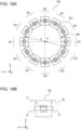
- Figs. 16A to 16D are views illustrating schematic configurations of an actuator unit 402 according to the fourth embodiment.
- Fig. 16A , 16C, and 16D are respectively a plan view (top view), a side view, and a perspective view of the actuator unit 402.
- Fig. 16B is a plan view in which outer members 90 and 92 and a displacement suppressing portion 29 are not illustrated.
- the actuator unit 402 three vibration body units 40 are held by a cylindrical outer member 92.
- the holding portions 8 that respectively hold the vibration bodies 1 are coupled by coupling portions 14h described below and are disposed on the circumference of the outer member 92.
- the contact body 91 has an annular (ring-like) shape and one of xy-surfaces thereof contacts the projecting portions 2a of the three vibration bodies 1 in a state in which the contact body 91 is rotatably supported by a rotational support mechanism (not shown).
- the rotational support mechanism of the contact body 91 is, for example, an axial support mechanism including a ball-and-roller bearing, a plain bearing, or the like.
- the outer member 90 is attached to the other xy-surface of the contact body 91.
- the actuator unit 402 when the vibration body units 40 are driven, the contact body 91 and the outer member 90 rotate in an integrated manner relative to the outer member 92 around an axis that passes through the center of the xy-surface of the outer member 90 and that is parallel to the z-axis. That is, the actuator unit 402 outputs the rotational motion of the outer member 90 to the outside as motive power.
- the vibration body unit 40 includes the holding portion 8, the vibration body 1, the pressing portion 7, and a spacer to which a nonwoven cloth (not shown) is affixed.
- a structure with which the vibration body 1 is pressed against the contact body 91 by using the pressing portion 7 is similar to the structure with which the vibration body 1 is pressed against the contact body 4 by using the vibration body unit 5, which has been described regarding the vibration actuator 101 (see Fig. 7 ).
- the vibration bodies 1 of the three vibration body units 5 can become displaced to follow the deformation of the contact body 4 even if deformation such as warping or the like has occurred in the contact body 4 in the circumferential direction.
- the coupling portion 14h is constrained by the displacement suppressing portion 29 fixed to the outer member 92.
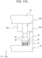
- the actuator unit 402 is configured by using three vibration body units 40 has been described with reference to Figs. 16A to 16D , it is possible to provide a similar actuator unit by using an annular vibration body 98 instead of the vibration body 1 as illustrated in Figs. 17A to 17C .
- Figs. 17A to 17C are views illustrating schematic configurations of another actuator unit according to the fourth embodiment.
- Figs. 17A and 17B are sectional views of the actuator unit
- Fig. 17C is a perspective view of the vibration body 98.
- the vibration body 98 includes a ring-shaped elastic body 94 and an electric-mechanical energy conversion element 95 joined to a bottom surface of the elastic body 94.
- the elastic body 94 has a comb-tooth shape in which a plurality of grooves are provided on the upper surface side (the elastic body 94 side) in the circumferential direction.
- a flexible substrate (not shown) is joined to the electric-mechanical energy conversion element 95, and a nonwoven cloth 96 is provided below the flexible substrate in the z-axis direction.
- a pressing portion 97 is inserted below the nonwoven cloth 96 in the z-axis direction.
- the pressing portion 97 includes a plurality of coil springs arranged in the circumferential direction, a coned-disc spring, a wave washer, or the like.
- the elastic body 94 is pressed against a contact body 84a.
- a vibration-damping member 85a is joined to each of an inner peripheral surface and an outer peripheral surface of the contact body 84a.
- the vibration-damping member 85a is similar to the vibration-damping members 25 and 35 described above.
- the elastic body 94 is pressed against a contact body 84b.
- the rigidity of a contact portion 84d in the z-direction is reduced by providing the contact body 84b with a flange portion 84c where the contact body 84b is cut out in the circumferential direction.
- a vibration-damping member 85b is joined to each of an inner peripheral surface and an outer peripheral surface of the contact body 84b.
- the vibration-damping member 85b is similar to the vibration-damping members 25 and 35 described above.
- the actuator unit by selecting the configuration of the vibration actuator in accordance with the specifications of an apparatus to which the actuator unit is to be applied and by appropriately adjusting the arrangement and the number of vibration body units.
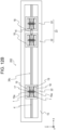
- FIG. 18 is a plan view illustrating a schematic configuration of an apparatus 501 according to the fifth embodiment.
- the apparatus 501 includes six vibration actuators 102 and a support member 350.
- the six vibration actuators 102 are fixed to the support member 350 via the support member 15 and with the support member 15 as a reference position.
- the support member 350 corresponds to the support member 15 magnified in the xy-plane, and is configured as one member.
- the six vibration actuators 102 it is easy to arrange the six vibration actuators 102 to be aligned on a plane. For example, it is easy to align and arrange the six vibration actuators 102 so as to be separated from a reference position J of the support member 350 by a distance d in the y-direction and so that the arrangement interval between adjacent support members 15 in the x-direction is a distance e. In this case, it is possible to make the intervals between the contact bodies 4 of the vibration actuators 102 that are adjacent in the x-direction be the same distance f.
- the vibration body units 11 of the six vibration actuators 102 may be coupled to one drive component (load) or may be coupled to different drive components (loads).
- the apparatus 501 described here includes the six vibration actuators 102, and it is possible to configure a similar apparatus by using any plurality of vibration actuators 102. Depending on the configuration of the apparatus, a plurality of vibration actuators can be disposed at different positions on the same plane or on different planes.
- the vibration actuator 102 As described above, it is possible to set the width dimension of the contact body 4 in the x-direction as small as possible and to suppress unnecessary vibration by using the vibration-damping member 35. Accordingly, it is possible to reduce the size of the apparatus when the plurality of vibration actuators 102 are arranged in the x-direction and used as in the apparatus 501. Moreover, it is possible to further reduce the size by arranging the vibration actuators 102 so as to contact each other as illustrated in Fig. 18 .
- the support member 15 and the support member 350 of the vibration actuator 102 are formed as an integrated component to make the dimension of the support member in the x-direction as small as possible in a range such that the vibration body unit 11 does not interfere.
- Figs. 19A and 19B are views illustrating schematic configurations of an apparatus 502 according to the sixth embodiment.
- Fig. 19A is a plan view of the apparatus 502
- Fig. 19B is a side view illustrating a schematic configuration of a vibration actuator 201 of the apparatus 502.
- the apparatus 502 includes twelve vibration actuators 201 and a support member 360.
- the support member 360 is formed by integrating twelve support members 15 of the twelve vibration actuators 201 into one member having a prismatic shape so that the cross section thereof perpendicular to the y direction has a substantially regular dodecagonal shape centered at a point K with the y direction as the axial direction.
- the twelve vibration actuators 201 are radially fixed respectively to twelve side surfaces (surfaces parallel to the y-axis) corresponding to the sides of the substantially regular dodecagonal shape of the zx cross section of the support member 360 via the support members 15 and with reference to the support members 15.
- the apparatus 502 it is possible to arrange the plurality of contact bodies 4 with high precision on the circumference of a pitch circle 370 that has a diameter g and that is centered at the point K as seen from the y-direction.
- the width dimension of the contact body 4 as small as possible and suppressing unnecessary vibration by using the vibration-damping member, it is possible to set the diameter g small and to reduce the size of the apparatus 502.
- the support member 15 and the support member 360 of the vibration actuator 102 as an integrated component, it is possible to substantially reduce the size.
- the vibration actuators 201 are disposed on all side surfaces of the support member 360 in the apparatus 502, the vibration actuators 201 can be disposed at any positions on any side surfaces.
- the support member 360 is not limited to a dodecagonal prism and can be changed to any polygonal prism.
- a seventh embodiment will be described.
- a multi-axis stage including a vibration actuator will be described.
- Fig. 20 is a plan view illustrating a schematic configuration of a multi-axis stage 503 according to the seventh embodiment.
- the multi-axis stage 503 includes a fixed portion 41, an x-stage 42, a y-stage 43, and an xy-stage 44.
- the degree of freedom of the fixed portion 41 is constrained in all directions, and the fixed portion 41 is immovable.
- four actuator units 401 (see Figs. 15A to 15D ) are arranged in the y-direction and fixed to the fixed portion 41.
- Four contact bodies 4 of the four actuator units 401 fixed to the fixed portion 41 are movable in the x-direction in Figs. 15A to 15D , and a right end of each of the contact bodies 4 is fixed to the x-stage 42.
- the x-stage 42 is movable only in the x-direction, the degree of freedom in the other directions are constrained, and the x-stage 42 is driven in the x-direction by the four actuator units 401 fixed to the fixed portion 41.
- Two actuator units 401 are fixed to the x-stage 42 to be arranged in the x-direction.
- Two contact bodies 4 of the two actuator units 401 fixed to the x-stage 42 are movable in the y-direction in Fig. 20 , and an upper end of each of the contact bodies 4 is fixed to the y-stage 43.
- the y-stage 43 is movable only in the y-direction, the degree of freedom in the other directions are constrained, and the y-stage 43 is driven in the y-direction by the two actuator units 401 fixed to the x-stage 42.
- the xy-stage 44 is fixed to the y-stage 43.
- the xy-stage 44 moves in the xy-plane in accordance with the movement of the x-stage 42 and/or the y-stage 43.
- a mass that the actuator units 401 provided on the fixed portion 41 move is larger than a mass that the actuator units 401 provided on the x-stage 42 move.
- the number of actuator units 401 to be disposed on the fixed portion 41 and the number of actuator units 401 to be disposed on the x-stage 42 may be set in correspondence with the mass of an object be moved.
- the multi-axis stage 503 is configured as an xy-stage having two degrees of freedom, it is possible to realize a stage having any degrees of freedom by using a plurality of actuator units 401.
- the multi-axis stage 503 is configured so that the plurality of actuator units 401 move an object to be driven in a predetermined direction, generation of a moment in a plane parallel to the xy-plane is suppressed. As a result, it is possible to move the xy-stage 44 with high precision in the xy-plane.
- an eighth embodiment will be described.
- an articulated robot including a vibration actuator as a driving source will be described.
- Fig. 21 is a plan view illustrating a schematic configuration of an articulated robot 505 according to the eighth embodiment.
- the articulated robot 505 is an example of an articulated robot using an antagonistic drive method.
- the articulated robot 505 includes a first joint 52, a fixed portion 54, a first pulley 55, a first link 56, a second link 57, a second joint 58, a second pulley 59, a third pulley 60, a wire 51e, and a wire 53e.
- the actuator units 401 will be denoted with symbols E1, F1, E2, and F2.
- the first joint 52 has a rotational degree of freedom such that the first joint 52 is rotatable around an axis parallel to the z-axis and centered at a point L.
- the second joint 58 has a rotational degree of freedom such that the second joint 58 is rotatable around an axis parallel to the z-axis and centered at a point M, and is constrained by motion of the first link 56.
- the first pulley 55 shown by a broken line, is constrained by the first link 56, and is provided to be rotatable around the first joint 52.
- the second link 57 is provided to be rotatable around the second joint 58 via the second joint 58.
- the second pulley 59 is constrained by the second link 57.
- the third pulley 60 is provided to be rotatable around the first joint 52.
- the wire 51e is wound around the first pulley 55, one end thereof is linked to the contact body 4 of the actuator unit F1, and the other end thereof is linked to the contact body 4 of the actuator unit E1.
- the wire 53e is wound around the third pulley 60, one end thereof is linked to the contact body 4 of the actuator unit F2, and the other end thereof is linked to the contact body 4 of the actuator unit E2.
- a wire 53a has an endless shape (loop shape) and is looped over the second pulley 59 and the third pulley 60.
- the actuator units E1 and F1 are each disposed so that the movement direction of the contact body 4 is the y-direction in Figs. 16A to 16D , and drive the wire 51e in the y-direction.
- the actuator units E1 and F1 generate thrusts in the y-direction so that the wire 51e may not slacken, a frictional force is generated between the wire 51e and the first pulley 55 due to the difference between the generated thrusts, and it is possible to rotate the first link 56 around the first joint.
- the actuator units E1 and F1 can generate a displacement of the first link 56 at an angle ⁇ 1 with respect to the x-axis.
- the actuator units E2 and F2 are each disposed so that the contact body 4 is movable in the x-direction in Fig. 21 , and drive the wire 53e in the x-direction.
- the actuator units E2 and F2 generate thrusts in the x-direction so that the wire 53e may not slacken, a frictional force is generated between the wire 53e and the third pulley 60 due to the difference between the generated thrusts. Due to the frictional force, the third pulley 60 rotates, the second pulley 59 moves together via the wire 53a, and it is possible to drive the first link 56 and the second link 57 around the first joint 52 and around the second joint 58.
- the vibration actuators E2 and F2 it is possible for the vibration actuators E2 and F2 to generate a displacement of the first link 56 at an angle ⁇ 1 with respect to the x-axis and to generate a displacement of the second link 57 at an angle ⁇ 2 with respect to the first link 56. Moreover, it is also possible to generate only the displacement of the second link 57 at the angle ⁇ 2 by driving the vibration actuators E1 and F1 so as to cancel the displacement of the first link 56 at the angle ⁇ 1 generated due to driving of the vibration actuators E2 and F2.
- the articulated robot 505 can cause a leading end N of the second link 57 to reach a target position in the xy-plane.
- the articulated robot 505 By performing antagonistic motion in a state in which a tension is constantly applied so that the wires 51e and 53e may not slacken, it is possible to suppress generation of deviation due to wobbling around a joint or buckling of the wires 51e and 53e. As a result, it is possible to increase torsional rigidity around each joint and to position the leading end N with high precision.
- a ninth embodiment will be described.
- an articulated robot including a vibration actuator as a driving source will be described.
- Fig. 22 is a plan view illustrating a schematic configuration of an articulated robot 506 according to the ninth embodiment.
- the articulated robot 506 operates by using a driving method in which a wire is pushed and pulled in a range of thrust such that a wire does not buckle.
- the articulated robot 506 includes the apparatus 502 and a wire-driven manipulator 504.
- Fig. 23 is a perspective view illustrating a schematic configuration of the wire-driven manipulator 504.
- the wire-driven manipulator 504 is, for example, equivalent to that described in PTL 2.
- the wire-driven manipulator 504 includes a linear-member guide portion 61 and two bending sections 66a and 66b.
- a linear member 62 can change the curvatures of the bending sections 66a and 66b by sliding in a hollow portion of a guide tube 65, which is provided in the linear-member guide portion 61, without buckling.
- the linear-member guide portion 61 may be flexible as illustrated in Fig. 22 .
- three linear members 62 are provided for each bending section.
- leading ends of three linear members are fixed to a guide member 63a, one linear member is fixed to guide members 64a, and the other two linear members are driven to change the curvature of the bending section 66a.
- leading ends of the remaining three linear members 62 are fixed to a leading end member 63b, one of the linear members is fixed to guide members 64b, and the other two linear members are driven to change the curvature of the bending section 66b.
- the apparatus 502 (see Figs. 19A and 19B ) is used as a driving source of the wire-driven manipulator 504.
- the contact bodies 4 of the vibration actuators 201 of the apparatus 502 are linked to the linear members 62, and are used as a driving source for changing the curvatures of the bending sections 66a and 66b of the wire-driven manipulator 504.
- the articulated robot 506 by driving the wire-driven manipulator 504 by using the apparatus 502, it is possible to control the curvatures of the bending sections 66a and 66b with high precision. Moreover, by using the apparatus 502 as a driving portion that drives the wire-driven manipulator 504, it is possible to reduce the size and weight of the driving portion to improve operability. Furthermore, by increasing and decreasing the number of vibration body units in the apparatus 502, it is possible to easily comply with output power required for the bending sections 66a and 66b. In addition, by using a direct-drive vibration actuator to drive the linear member 62 of the wire-driven manipulator 504, it is possible to improve responsivity compared with a case where a driving unit in which an electromagnetic motor and a speed reduction mechanism are combined.
- the plurality of vibration actuators 201 of the apparatus 502 include a plurality of vibration body units 20 using common components, it is possible to change the output power from each of the vibration actuators 201 by increasing and decreasing the vibration body units 20. Moreover, by changing the amplitude ratio of vibrations in a plurality of vibration modes excited in the vibration body 1, it is also possible to control the magnitude of thrust for driving (deforming) the bending sections 66a and 66b and driving speed. When a voltage is not applied to the electric-mechanical energy conversion element 3, it is possible to maintain the postures of the bending sections 66a and 66b by using a frictional force that acts between the projecting portions 2a and the contact body 4.
- the articulated robot 506 is applicable to, for example, an industrial endoscope, a medical endoscope, and a surgical instrument such as a catheter used in medical practices such as treatment, biopsy, and inspection.
- the articulated robot 506 has four degrees of freedom with the two bending sections 66a and 66b, the number of bending sections, that is, the degree of freedom can be set to any appropriate number.
- the shape of the support member 360, the diameter g of the pitch circle 370, and the number and the disposition of the vibration actuator 201 may be set to any appropriate conditions with respect to the apparatus 502, in accordance with the number of bending sections and the diameter of the guide member.
- an object to be coupled which is to be coupled with the vibration body unit via the coupling portion
- an object to be coupled is not limited to any of these and may be any portion or component that is movable relative to the contact body.
- the multi-axis stage 503 and the articulated robots 505 and 506 have been described as examples of an apparatus to which the vibration actuator and the actuator unit according to each of the embodiments are applied, an apparatus to which the vibration actuator and the actuator unit are appliable is not limited to any of these.
- an apparatus includes: various stage apparatuses for a microscope, a machine tool, and a measurement apparatus; and robots such as a vertical articulated robot, a parallel-link robot, and the like having a larger degree of freedom than the articulated robot 505.
Landscapes
- Engineering & Computer Science (AREA)
- Robotics (AREA)
- Mechanical Engineering (AREA)
- General Electrical Machinery Utilizing Piezoelectricity, Electrostriction Or Magnetostriction (AREA)
Abstract


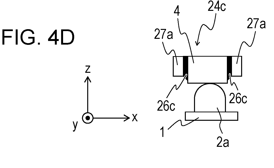
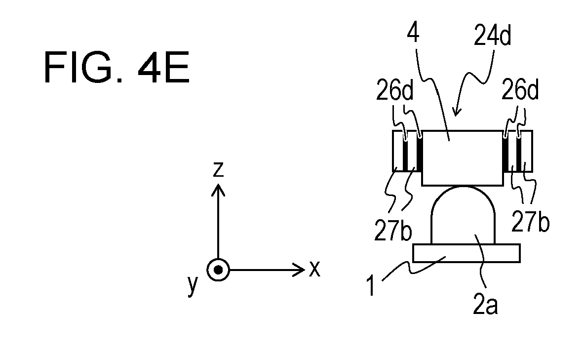
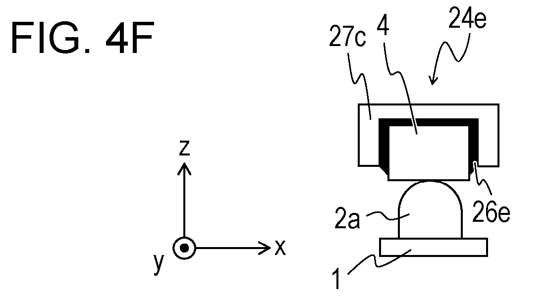
Description
- The present invention relates to a vibration actuator in which a vibration body and a contact body move relative to each other, a contact body unit, an actuator unit using the vibration actuator, an apparatus, a multi-axis stage unit, and an articulated robot.
- There have been proposed: a vibration actuator that obtains thrust between a vibration body and a contact body by generating, in the vibration body, vibration in which different vibration modes are combined; and a vibration actuator that changes a frictional force between a vibration body and a contact body by causing excitation in a single vibration mode.
-
PTL 1 discloses, regarding a vibration motor (corresponding to a vibration actuator) including a vibrator (corresponding to a vibration body) that generates an elliptic motion in which a plurality of different vibrations are synthesized, a configuration with which a vibration generated in a relative movement member (corresponding to a contact body) due to the elliptic motion generated by the vibrator is absorbed by providing a vibration-absorbing member between the relative movement member and a second base member. -
- PTL 1:
Japanese Patent Laid-Open No. 2000-324865 - PTL 2:
Japanese Patent Laid-Open No. 2018-140101 - However, with the configuration disclosed in
PTL 1, the output power per volume or per weight tends to be small, and the configuration has a problem in space efficiency. A first reason for this is that the second base member is necessary. The second base member, which is illustrated to be larger than the relative movement member, increases the size of the entirety of the vibration motor and makes reduction in size difficult. A second reason is that a limitation is imposed on an embodiment of the vibration motor. Since the vibration-absorbing member is provided between the relative movement member and the second base member, a surface that can be used for frictional sliding of the relative movement member is inevitably limited. Therefore, the vibration-absorbing member is affixed to a surface that faces a frictional sliding surface, and the surface cannot be used for driving. - The present invention has been made against the background described above, and an object thereof is to suppress unnecessary vibration generated in a vibration actuator and to prevent output power per volume or per weight from becoming small.
- A vibration actuator according to the present invention includes: a vibration body including an elastic body and an electric-mechanical energy conversion element joined to the elastic body; and a contact body that contacts the vibration body. The vibration body and the contact body move relative to each other in a predetermined direction. A vibration-damping member is provided on a predetermined surface of the contact body that is different from a contact surface that contacts the vibration body.
- With the present invention, it is possible to suppress unnecessary vibration generated in a vibration actuator and to prevent output power per volume or per weight from becoming small.
-
-
Fig. 1A is a view illustrating a schematic configuration of a vibration body. -
Fig. 1B is a view illustrating a schematic configuration of the vibration body. -
Fig. 1C is a view illustrating a schematic configuration of the vibration body. -
Fig. 2A is a view for describing a vibration mode that is excited in the vibration body. -
Fig. 2B is a view for describing a vibration mode that is excited in the vibration body. -
Fig. 2C is a view for describing the vibration mode that is excited in the vibration body. -
Fig. 3A is a view for describing a vibration actuator according to a first embodiment. -
Fig. 3B is a view for describing the vibration actuator according to the first embodiment. -
Fig. 3C is a view for describing the vibration actuator according to the first embodiment. -
Fig. 3D is a view for describing the vibration actuator according to the first embodiment. -
Fig. 4A is a view for describing an example of a contact body unit and a vibration body according to the first embodiment. -
Fig. 4B is a view for describing an example of the contact body unit and the vibration body according to the first embodiment. -
Fig. 4C is a view for describing an example of the contact body unit and the vibration body according to the first embodiment. -
Fig. 4D is a view for describing an example of the contact body unit and the vibration body according to the first embodiment. -
Fig. 4E is a view for describing an example of the contact body unit and the vibration body according to the first embodiment. -
Fig. 4F is a view for describing an example of the contact body unit and the vibration body according to the first embodiment. -
Fig. 4G is a view for describing an example of the contact body unit and the vibration body according to the first embodiment. -
Fig. 5A is a view illustrating a schematic configuration of a contact body unit according to the first embodiment. -
Fig. 5B is a view illustrating a schematic configuration of a contact body unit according to the first embodiment. -
Fig. 5C is a view illustrating a schematic configuration of a contact body unit according to the first embodiment. -
Fig. 6A is a view illustrating a schematic configuration of a contact body unit and a displacement-detecting portion according to the first embodiment. -
Fig. 6B is a view illustrating a schematic configuration of the contact body unit and the displacement-detecting portion according to the first embodiment. -
Fig. 6C is a view illustrating a schematic configuration of the contact body unit and the displacement-detecting portion according to the first embodiment. -
Fig. 7 is a view illustrating a schematic configuration of a vibration actuator according to the first embodiment. -
Fig. 8A is a view for describing a configuration of a vibration body unit of the vibration actuator according to the first embodiment. -
Fig. 8B is a view for describing a configuration of the vibration body unit of the vibration actuator according to the first embodiment. -
Fig. 8C is a view for describing a configuration of the vibration body unit of the vibration actuator according to the first embodiment. -
Fig. 9A is a view illustrating a schematic configuration of another vibration actuator according to the first embodiment. -
Fig. 9B is a view illustrating a schematic configuration of the other vibration actuator according to the first embodiment. -
Fig. 9C is a view illustrating a schematic configuration of the other vibration actuator according to the first embodiment. -
Fig. 10A is a view for describing an example of a contact body unit and a vibration body according to a second embodiment. -
Fig. 10B is a view for describing an example of the contact body unit and the vibration body according to the second embodiment. -
Fig. 10C is a view for describing an example of the contact body unit and the vibration body according to the second embodiment. -
Fig. 10D is a view for describing an example of the contact body unit and the vibration body according to the second embodiment. -
Fig. 10E is a view for describing an example of the contact body unit and the vibration body according to the second embodiment. -
Fig. 11 is a view illustrating a schematic configuration of a vibration actuator according to the second embodiment. -
Fig. 12A is a view illustrating a schematic configuration of another vibration actuator according to the second embodiment. -
Fig. 12B is a view illustrating a schematic configuration of the other vibration actuator according to the second embodiment. -
Fig. 13A is a view for describing another example of the contact body unit and the vibration body according to the second embodiment. -
Fig. 13B is a view for describing another example of the contact body unit and the vibration body according to the second embodiment. -
Fig. 13C is a view for describing another example of the contact body unit and the vibration body according to the second embodiment. -
Fig. 13D is a view for describing another example of the contact body unit and the vibration body according to the second embodiment. -
Fig. 13E is a view for describing another example of the contact body unit and the vibration body according to the second embodiment. -
Fig. 13F is a view for describing another example of the contact body unit and the vibration body according to the second embodiment. -
Fig. 14 is a view illustrating a state in which a displacement-detecting portion is attached to a vibration body unit according to the second embodiment. -
Fig. 15A is a view illustrating a schematic configuration of an actuator unit according to a third embodiment. -
Fig. 15B is a view illustrating a schematic configuration of the actuator unit according to the third embodiment. -
Fig. 15C is a view illustrating a schematic configuration of the actuator unit according to the third embodiment. -
Fig. 15D is a view illustrating a schematic configuration of the actuator unit according to the third embodiment. -
Fig. 16A is a view illustrating a schematic configuration of an actuator unit according to a fourth embodiment. -
Fig. 16B is a view illustrating a schematic configuration of the actuator unit according to the fourth embodiment. -
Fig. 16C is a view illustrating a schematic configuration of the actuator unit according to the fourth embodiment. -
Fig. 16D is a view illustrating a schematic configuration of the actuator unit according to the fourth embodiment. -
Fig. 17A is a view illustrating a schematic configuration of an actuator unit according to the fourth embodiment. -
Fig. 17B is a view illustrating a schematic configuration of the actuator unit according to the fourth embodiment. -
Fig. 17C is a view illustrating a schematic configuration of the actuator unit according to the fourth embodiment. -
Fig. 18 is a view illustrating a schematic configuration of an apparatus according to a fifth embodiment. -
Fig. 19A is a view illustrating a schematic configuration of an apparatus according to a sixth embodiment. -
Fig. 19B is a view illustrating a schematic configuration of the apparatus according to the sixth embodiment. -
Fig. 20 is a view illustrating a schematic configuration of a multi-axis stage according to a seventh embodiment. -
Fig. 21 is a view illustrating a schematic configuration of an articulated robot according to an eighth embodiment. -
Fig. 22 is a view illustrating a schematic configuration of an articulated robot according to a ninth embodiment. -
Fig. 23 a view illustrating a schematic configuration of a wire-driven manipulator of the articulated robot according to the ninth embodiment. - Hereafter, embodiments of the present invention will be described with reference to the attached drawings.
- First, a vibration body and a contact body that are used in common in vibration actuators according to the embodiments described below will be described.
-
Figs. 1A to 1C are views illustrating schematic configurations of avibration body 1 of the vibration actuator.Fig. 1A is a plan view of thevibration body 1,Fig. 1B is a front view of thevibration body 1, andFig. 1C is a side view of thevibration body 1. For convenience of description, as illustrated inFigs. 1A to 1C , an orthogonal coordinate system having an x-axis (x-direction), a y-axis (y-direction), and a z-axis (z-direction) is set for thevibration body 1. The z-direction is the thickness direction of thevibration body 1 and is a protruding direction of projectingportions 2a (described below in detail) that are provided at two positions. The y-direction is the longitudinal direction of thevibration body 1 and is a direction connecting the two projectingportions 2a. The x-direction is the transversal direction (width direction) of thevibration body 1 and is a direction perpendicular to the y-direction and the z-direction. Regarding each direction illustrated inFigs. 1A to 1C , a direction from the start point toward the end point of an arrow indicating the direction is defined as a positive direction (+direction), and a direction from the end point toward the start point is defined as a negative direction (-direction). - The
vibration body 1 includes anelastic body 2 and an electric-mechanicalenergy conversion element 3 joined to theelastic body 2. The electric-mechanicalenergy conversion element 3 is, for example, a piezoelectric element that converts a voltage to a force by using an inverse piezoelectric effect, and electrodes to which a predetermined voltage is applied are provided on the front and back surfaces of rectangular thin-plate-shaped piezoelectric ceramics. Theelastic body 2 includes the projectingportions 2a, suspendingsupport portions 2b,support end portions 2c, and abase portion 2d. Thebase portion 2d has a rectangular flat-plate-like shape, and the electric-mechanicalenergy conversion element 3 is joined to thebase portion 2d. The two projectingportions 2a are provided on thebase portion 2d so as to protrude in the +z-direction from a surface opposite to a surface to which the electric-mechanicalenergy conversion element 3 is joined. The projectingportions 2a may be formed by press working the elastic body 2 (thebase portion 2d) or by joining projecting members to thebase portion 2d by using a predetermined method. The suspendingsupport portions 2b are rectangular flat-plate-shaped portions that are provided at both ends of thebase portion 2d in the y-direction and that serve to connect thebase portion 2d and thesupport end portions 2c. Thesupport end portions 2c are rectangular flat-plate-shaped portions for fixing thevibration body 1 to a holdingportion 8 described below. - Here, the projecting
portion 2a will be described in detail.Fig. 2C is a cross-sectional view illustrating a schematic structure of the projectingportion 2a. Afriction material 2f is provided on a surface of aparent material 2e of the projectingportion 2a. Here, the material of theparent material 2e is the same as that of thebase portion 2d. When martensitic stainless steel is used for theparent material 2e, it is possible to use electroless nickel plating, chrome plating, a quench-hardened layer, a nitride film formed by ion nitriding treatment, or the like as thefriction material 2f. By using a fiber-reinforced engineering plastic such as PEEK-CF30 or hard ceramics as theparent material 2e, it is also possible to use a configuration such that theparent material 2e serves also as thefriction material 2f (in this case, there is no distinction between theparent material 2e and thefriction material 2f). - Next, referring to
Figs. 2A to 2C , two vibration modes (vibration forms) that are excited in thevibration body 1 will be described.Figs. 2A to 2C illustrate the vibration modes excited in thevibration body 1.Fig. 2A is a view for describing a first vibration mode, andFig. 2B is a view for describing a second vibration mode. InFigs. 2A to 2C , deformation of thevibration body 1 is illustrated with exaggeration. For convenience of description, acontact body 4 that contacts thevibration body 1 and receives thrust (frictional driving force) from thevibration body 1 is illustrated. - The
contact body 4 is a member that contacts the projectingportions 2a of thevibration body 1. Due to vibration generated in thevibration body 1, thevibration body 1 and thecontact body 4 move relative to each other in the y-direction as described below. Contact between thevibration body 1 and thecontact body 4 is not limited to direct contact such that another member is not interposed between thevibration body 1 and thecontact body 4. As long as thevibration body 1 and thecontact body 4 move relative to each other due to vibration generated in thevibration body 1, contact between thevibration body 1 and thecontact body 4 may be indirect contact such that another member is interposed between thevibration body 1 and thecontact body 4. - The first vibration mode illustrated in
Fig. 2A is a secondary out-of-plane bending vibration mode in which three nodal lines that are substantially parallel to the x-direction are generated in thebase portion 2d. Due to the first vibration mode, vibrations that become displaced in the y-direction are generated at end portions of the two projectingportions 2a. The second vibration mode illustrated inFig. 2B is a primary out-of-plane bending vibration mode in which two nodal lines that are substantially parallel to the y direction are generated in thebase portion 2d. Due to the second vibration mode, vibrations that become displaced in the z-direction are generated at the end portions of the two projectingportions 2a. - By simultaneously generating vibration in the first vibration mode and vibration in the second vibration mode by applying a plurality of alternating voltages having different phases to the electric-mechanical
energy conversion element 3, it is possible to generate, at the end portions of the two projectingportions 2a, an elliptic motion in the yz-plane in which the vibrations are combined. When the elliptic motion is generated in the yz-plane at the end portions of the two projectingportions 2a, thecontact body 4 receives thrust in the y-direction, and, as a result, it is possible to move thevibration body 1 and thecontact body 4 relative to each other in the y-direction. - In a state in which a voltage is not applied to the electric-mechanical
energy conversion element 3, a static frictional force between the projectingportions 2a and thecontact body 4 serves as a holding force for maintaining the relative positions of thevibration body 1 and thecontact body 4. Moreover, by adjusting the amplitude of vibration generated in thevibration body 1 by adjusting a voltage applied to the electric-mechanicalenergy conversion element 3, it is possible to adjust the contact time between the projectingportions 2a and thecontact body 4 to change apparent frictional force. Furthermore, by generating only vibration in the second vibration mode in thevibration body 1 and controlling the amplitude of the vibration, it is possible to change a frictional force generated between the projectingportions 2a and thecontact body 4. By using these, for example, in a configuration such that thecontact body 4 moves relative to thevibration body 1, it is possible to adjust the magnitude of a reaction force when thecontact body 4 is moved by applying an external force (a force applied from a source other than the vibration body 1) to thecontact body 4. For example, it is possible to adjust an operational reaction force that a user receives when the user performs an operation by directly applying an external force to thecontact body 4. - As illustrated in
Figs. 2A to 2C , in the vibration actuator using thevibration body 1, the end portions of the two projectingportions 2a contact thecontact body 4. Afriction material 4a is provided on a surface thecontact body 4 that is a contact surface (frictional sliding surface) that contacts the projectingportions 2a. As described above, thefriction material 2f is provided on the surface of the projectingportions 2a. Thus, it is possible to obtain stable frictional sliding characteristics between thevibration body 1 and thecontact body 4. The material of thefriction material 4a and a method of forming thefriction material 4a may be similar to those of thefriction material 2f. - Next, materials used for the
vibration body 1 and thecontact body 4 will be described. Examples of the material of theelastic body 2 of thevibration body 1 include martensitic stainless steel whose vibration loss is small and high-toughness ceramics such as partially-stabilized zirconia (PSZ). Other examples the material include engineering plastics (FRP) such as polyether ether ketone (PEEK-CF30) reinforced by carbon fiber of about 30 wt%, semiconductors such as silicon carbide (SiC), and aluminum alloys. Examples of the material of the electric-mechanicalenergy conversion element 3 of thevibration body 1 include piezoelectric ceramics such as lead zirconate titanate (PZT). Examples of the material of thecontact body 4 include martensitic stainless steel, aluminum alloys, FRP such as PEEK-CF30, and fine ceramics such as PSZ or alumina (aluminum oxide). The materials of thevibration body 1 and thecontact body 4 are not limited to those listed here. - Referring to
Figs. 3A to 9C , a first embodiment will be described. -
Figs. 3A to 3D are views for describing the vibration actuator according to the first embodiment, and schematically illustrate thevibration body 1 and thecontact body 4. -
Fig. 3A is a front view of thecontact body 4 and onevibration body 1 pressed against (in pressed contact with) thecontact body 4. In accordance with the x-direction, the y-direction, and the z-direction that are set for thevibration body 1, an x-direction, a y-direction, and a z-direction are set as illustrated inFigs. 3A to 3D . Including vibration actuators according to other embodiments described below, the y-direction is defined as the left-right direction of the vibration actuator, the +y side is defined as the right side, and the -y side is defined as the left side. The z-direction is the up-down direction of the vibration actuator, the +z side is defined as the upper side, and the -z side is defined as the lower side. Exemplary configurations for pressing thevibration body 1 against thecontact body 4 will be described below. -
Fig. 3B is a front view of thecontact body 4, illustrating, with exaggeration, the vibration form of an out-of-plane bending mode generated in thecontact body 4. When the first vibration mode, the second vibration mode, or both of these is/are excited with a predetermined drive frequency in thevibration body 1, a natural vibration mode is excited in thecontact body 4 if the drive frequency is close to the natural frequency of the natural vibration mode of thecontact body 4. For example, when an out-of-plane vibration mode that vibrates in the z-direction at a wavelength λ with respect to a plane parallel to the xy-plane as illustrated inFig. 3B is excited in thecontact body 4, theprojections 2a of thevibration body 1 and thecontact body 4 intermittently repeat a contact state and a non-contact state. Thus, contact between theprojections 2a and thecontact body 4 becomes unstable, and, in addition, beating noise is generated and thrust decreases. Moreover, the difference between a drive frequency exited in thevibration body 1 and the natural frequency of the natural vibration mode of thecontact body 4 generates noise, and thrust may decrease. - This unnecessary vibration is generated not only in the
contact body 4 having a bar-like shape as illustrated inFigs. 3A and 3B . For example, the same applies to acontact body 91 having an annular shape as illustrated inFigs. 3C and 3D . Specific exemplary configurations of a vibration actuator using theannular contact body 91 will be described in detail in the following embodiments.Fig. 3D is a perspective view of thecontact body 91 in which an out-of-plane bending mode generated in thecontact body 91 is illustrated with exaggeration. Also in this case, when vibration is exited in thevibration body 1, a natural vibration mode is excited in thecontact body 91 if the drive frequency of the vibration is close to the natural frequency of the natural vibration mode of thecontact body 91. For example, as illustrated inFig. 3D , when an out-of-plane vibration mode that vibrates in the z-direction at a wavelength λ with respect to a plane parallel to the xy-plane is excited in thecontact body 91 and the shape of thecontact body 91 is close to a circular shape, the excited out-of-plane vibration forms a progressive wave to become an amplified unnecessary vibration, and causes decrease in performance due to similar unnecessary vibration. - Hereafter, referring to
Figs. 4A to 6C , measures to suppress unnecessary vibration generated in thecontact body 4 in the first embodiment will be described. -
Figs. 4A to 4G are right-side views for describing examples of a contact body unit and thevibration body 1 pressed against the contact body unit.Figs. 5A to 5C are bottom views illustrating schematic configurations of some of the contact body units illustrated inFigs. 4A to 4G . -
Fig. 4A is a view illustrating the basic configuration of a contact body unit according to the first embodiment, which is a configuration such that onevibration body 1 is pressed against thecontact body 4 of acontact body unit 24. Thecontact body unit 24 is configured by joining a vibration-dampingmember 25 to a predetermined surface of thecontact body 4 that is different from the contact surface, which is both side surfaces of thecontact body 4 in the x-direction here. In this way, the vibration-dampingmember 25 is provided on both of the side surfaces of thecontact body 4 in the x-direction that are connected to the contact surface and face each other. A lower end of each of the vibration-dampingmembers 25 is configured to be located above a lower end of thecontact body 4, that is, the contact surface in the z-direction. With the shape such that an end portion of the vibration-dampingmember 25 does not protrude further than the contact surface in this way, it is easy to grind (polish) the contact surface to improve smoothness and surface roughness even after thecontact body unit 24 has been assembled. As described below in detail, the vibration-dampingmember 25 is constituted by a viscoelastic body or by a combination of a viscoelastic body and a reinforcement member. -
Figs. 4B to 4G are views for describing exemplary configurations of the vibration-damping member, illustrating configurations such that onevibration body 1 is pressed against thecontact body 4 of the contact body unit. -
Fig. 4B is a view illustrating acontact body unit 24a, which is an example in which the vibration-damping member includes only aviscoelastic body 26a.Fig. 5A is a bottom view of thecontact body unit 24a. In thecontact body unit 24a, theviscoelastic body 26a is joined to both side surfaces of thecontact body 4 in the x-direction. It is assumed that the mechanical quality factor Q of theviscoelastic body 26a is lower than that of thecontact body 4. As the material of theviscoelastic body 26a, a material having both of viscosity and elasticity such as rubber or resin is suitable. As a rubber material, butadiene rubber, butyl rubber, silicon rubber, or the like having high vibration-damping performance is suitable. When theviscoelastic body 26a is joined to thecontact body 4, internal strain is generated in theviscoelastic body 26a in accordance with strain of the joining surface generated in accordance with deformation of thecontact body 4 in a natural vibration mode excited in thecontact body 4 as unnecessary vibration. By using this, it is possible to cause the viscoelastic body to absorb vibration energy and to reduce the vibration amplitude of unnecessary vibration generated in thecontact body 4. -
Fig. 4C is a view illustrating acontact body unit 24b, which is an example in which the vibration-damping member includes only aviscoelastic body 26b that is joined also to a back surface of thecontact body 4, which is a surface opposite to the contact surface. A bottom view, which is similar toFig. 5A , is omitted. In thecontact body unit 24b, theviscoelastic body 26b is joined to three surfaces (both side surfaces in the x-direction and the back surface) of thecontact body 4 by fitting thecontact body 4 into a groove portion in theviscoelastic body 26b having a recessed cross-sectional shape. As described above, rubber or resin is suitable as the material theviscoelastic body 26b. For example, thecontact body unit 24b may be configured by using a resin material having a large attenuation coefficient and by fitting thecontact body 4 and viscoelastic body to each other. By joining theviscoelastic body 26b to the three surfaces of thecontact body 4, it is possible to increase region for absorbing vibration energy in accordance with strain generated in accordance with deformation of thecontact body 4 and to increase the effect of suppressing unnecessary vibration compared with thecontact body unit 24a. -
Fig. 4D is a view illustrating acontact body unit 24c, which is an example in which the vibration-damping member includes a combination of aviscoelastic body 26c and areinforcement member 27a.Fig. 5B is a bottom view of thecontact body unit 24c. In thecontact body unit 24c, theviscoelastic body 26c is joined to both side surfaces of thecontact body 4 in the x-direction, and thereinforcement member 27a is joined to theviscoelastic body 26c. In this way, theviscoelastic body 26c is interposed between thecontact body 4 and thereinforcement member 27a. As described above, rubber or resin is suitable as the material of theviscoelastic body 26c, and a double-sided tape or an adhesive may be used additionally. It is assumed that the mechanical quality factor Q of theviscoelastic body 26c is lower than that of each of thecontact body 4 and thereinforcement member 27a. As the material of thereinforcement member 27a, a material whose elastic modulus is sufficiently higher than that of theviscoelastic body 26c is suitable. For example, various metals, ceramics, engineering plastic, and the like are usable, and the material may be the same as that of thecontact body 4. When thereinforcement member 27a is joined to thecontact body 4 via theviscoelastic body 26c, both side surfaces of theviscoelastic body 26c are joined to thecontact body 4 and thereinforcement member 27a. Since the displacement distribution of theviscoelastic body 26c is restrained at the joint surface with thereinforcement member 27a having a larger elastic modulus, it is possible to absorb vibration energy by generating shearing strain of theviscoelastic body 26c due to deformation of thecontact body 4 and to reduce the vibration amplitude of unnecessary vibration generated in thecontact body 4. -
Fig. 4E is a view illustrating acontact body unit 24d, which is an example in which the vibration-damping member has a multilayer structure in which a plurality ofviscoelastic bodies 26d and a plurality ofreinforcement members 27b are alternately arranged.Fig. 5C is a bottom view of thecontact body unit 24d. In thecontact body unit 24d, aviscoelastic body 26d and areinforcement member 27b are joined from both sides of thecontact body 4 in the x-direction and another set of aviscoelastic body 26d and areinforcement member 27b are further joined. The materials of theviscoelastic body 26d and thereinforcement member 27b are similar to those described with reference toFig. 4D . When the vibration-damping member has a multilayer structure in which the plurality of theviscoelastic bodies 26d and the plurality of thereinforcement members 27b are alternately arranged, it is possible to increase vibration energy to be absorbed by generating shearing strain. Thus, it is possible to more effectively reduce the vibration amplitude of unnecessary vibration generated in thecontact body 4. Moreover, compared a case of thecontact body unit 24c, it is possible to reduce the thickness of theviscoelastic body 26d in the x-direction. By reducing the thickness of theviscoelastic body 26d, it is possible to reduce displacement of the vibration-damping member in the xy-plane when an external force is applied to thecontact body unit 24d via thereinforcement member 27b. Accordingly, in a case where a linear guide that linearly guides thecontact body unit 24d is configured by supporting thereinforcement member 27b that is exposed on a side surface, it is possible to improve the rigidity of the linear guide, compared with a case of thecontact body unit 24c. Thus, it is possible to position thecontact body 4 with high precision. -
Fig. 4F is a view illustrating acontact body unit 24e, which is an example in which the vibration-damping member includes a combination of aviscoelastic body 26e and a reinforcement member 27c and is joined also to the back surface of thecontact body 4. A bottom view, which is similar toFig. 5B , is omitted. In thecontact body unit 24e, theviscoelastic body 26e is joined to three surfaces (both side surfaces in the x-direction and the back surface) of thecontact body 4 by fitting thecontact body 4 into a groove portion of theviscoelastic body 26e having a recessed cross-sectional shape. Moreover, the reinforcement member 27c is joined to three surfaces (both side surfaces in the x-direction and the back surface) of theviscoelastic body 26e by fitting theviscoelastic body 26e into a groove portion of the reinforcement member 27c having a recessed cross-sectional shape. That is, this is an example of a combination of the configuration of thecontact body unit 24b illustrated inFig. 4C and the configuration of thecontact body unit 24c illustrated inFig. 4D . The materials of theviscoelastic body 26e and the reinforcement member 27c are similar to those described with reference toFig. 4D . Advantageous effects due to this configuration are also similar to those described with reference toFig. 4C andFig. 4D . -
Fig. 4G is a view illustrating acontact body unit 24f, which is an example in which the vibration-damping member includes a combination of aviscoelastic body 26f and areinforcement member 27d. In thecontact body unit 24f, theviscoelastic body 26f is joined to one side surface of thecontact body 4 in the x-direction (the left side surface in the illustrated example), and thereinforcement member 27d is joined to theviscoelastic body 26f. Here, an adhesive is used as theviscoelastic body 26f, and due to the wettability of the adhesive, theviscoelastic body 26f spreads to two flat surfaces (the contact surface and the back surface) of thecontact body 4 that are parallel to the xy-plane. In this case, the amount of the adhesive to become theviscoelastic body 26f is controlled so that the adhesive may not contact theprojection 2a of thevibration body 1. Thereinforcement member 27d has a length in the z-direction that exceeds the thickness of thecontact body 4 so as to receive the adhesive. In this way, end portions of the vibration-damping member (end portions of theviscoelastic body 26f, end portions of thereinforcement member 27d) protrude further than the contact surface and the back surface. The material of thereinforcement member 27d is similar to that described regarding thecontact body unit 24c with reference toFig. 4D . Also with thecontact body unit 24f, it is possible to obtain the advantageous effect of suppressing unnecessary vibration by absorbing excitation energy by using shearing strain of theviscoelastic body 26f. Since theviscoelastic body 26f spreads to two flat surfaces of the contact body parallel to the xy-plane, the adhesive strength of thereinforcement member 27d is increased, and absorption of excitation energy is performed as internal strain is generated in the viscoelastic body that has spread. Thus, it is possible to reduce the vibration amplitude of unnecessary vibration generated in thecontact body 4. - In the following description, various contact body units and vibration-damping members (viscoelastic bodies, reinforcement members) described with reference to
Figs. 4A to 4G may be referred to as thecontact body unit 24, the vibration-dampingmember 25, the viscoelastic body 26, and the reinforcement member 27 by using representative numerals. It is also possible to provide the vibration-dampingmember 25 with a function other than suppression of unnecessary vibration. - Referring to
Figs. 6A to 6C , an exemplary configuration such that the vibration-dampingmember 25 is provided with a displacement-detection function of detecting relative displacement of thevibration body 1 and thecontact body 4 will be described.Figs. 6A, 6B, and 6C are respectively a plan view, a front view, and a right-side view illustrating the positional relationship between acontact body unit 24g and adetector 83. In thecontact body unit 24g, theviscoelastic body 26c is joined to both side surfaces of thecontact body 4 in the x-direction, thereinforcement member 27a is joined to theviscoelastic body 26c, and a part of thereinforcement member 27a is replaced with ascale 27e. As illustrated inFig. 6B , thescale 27e is a reflective diffraction grating and has a pattern of reflective portions and non-reflective portions formed by removing a metal film, deposited on a glass surface, by etching or laser processing. In this case, thescale 27e is joined to theviscoelastic body 26c, and thus constrains a side surface of theviscoelastic body 26c and functions as a reinforcement member. In this way, a part of the vibration-dampingmember 25 constitutes thescale 27e. Thedetector 83 is set at a position that is separated by a gap from thescale 27e in the x-direction and that does not physically interfere with thescale 27e. Thedetector 83 includes a light source and a light receiver, and can read thescale 27e by emitting light from the light source to thescale 27e and receiving reflection of the light with the light receiver. In this way, thedetector 83 and thescale 27e constitute a displacement-detectingportion 28 and functions as a linear encoder that detects displacement in the y-direction. In this way, thescale 27e can have the effects and the functions of both of the vibration-dampingmember 25 and the displacement-detectingportion 28. By affixing thescale 27e via theviscoelastic body 26c, theviscoelastic body 26c serves as a vibration insulator that makes it difficult for vibration of thecontact body 4 to be transmitted thescale 27e, and thus it is possible to reduce displacement detection error due to vibration of thescale 27e. - Although the dimension of the
scale 27e in the z-direction is illustrated to be less than that of thecontact body 4 inFigs. 6A to 6C , as described above with reference toFig. 4G , thescale 27e may be configured to overhang toward the contact surface side of thecontact body 4. When thescale 27e overhangs, the area of the viscoelastic body 26 is increased, and it is possible to further increase the vibration-damping effect. As described below with reference toFig. 10E , by affixing reinforcement members to both side surfaces of the contact body and by providing at least one of them with a function of a scale, it is possible to expect a dustproof effect of reducing the amount of abrasion powder that is generated by frictional driving and scattered to the outside from the vicinity of the contact surface. As described above, by causing the viscoelastic body to protrude toward the contact surface side of the contact body and providing the viscoelastic body with adhesion, it is possible to trap abrasion powder generated by frictional driving and to increase the dustproof effect. - Although glass is used as the material of the
scale 27e, it is also possible to use a metal. Regarding a method of forming the reflective portions and the non-reflective portions, it is also possible to use another method such as electroforming or printing. Although thescale 27e and thereinforcement member 27a are illustrated as independent bodies inFigs. 6A to 6C , a film-shaped scale may be affixed to a side surface of the reinforcement member. It may be possible to form a scale by performing vapor deposition or printing on a side surface of the viscoelastic body. Although an exemplary configuration such that a scale is affixed to a side surface of the contact body via a viscoelastic body has been described above, this is not a limitation. For example, the contact body may be formed from a metal, protruding/recessed shapes may be formed on a side surface of the contact body by etching or electroforming, and a viscoelastic body may be injected into recessed portions. As a shape such that the viscoelastic body is disposed in the recessed portion is periodically repeated in the y-direction, the protruding portions serve as reflective portions and the viscoelastic body injected into the recessed portions serve as non-reflective portions. Thus, a function equivalent to that of a scale is realized, and it can be expected that the injected viscoelastic body suppresses unnecessary vibration in the same way as described above. - The
contact body units 24 described with reference toFigs. 4A to 6C are examples in which the vibration-dampingmember 25 is joined to thecontact body 4 over the entire area in the y-direction. However, this is not a limitation, and the vibration-dampingmember 25 may be joined to thecontact body 4 in a part in the y-direction. Although providing the vibration-dampingmember 25 over the entire area in the y-direction is effective in suppression of unnecessary vibration, providing the vibration-dampingmember 25 in a part in the y-direction makes it possible to achieve reduction in size, weight, and space, prevention of interference with other components, cost reduction, and the like. When the vibration-dampingmember 25 is to be provided in a part in the y-direction, determining the length of the vibration-dampingmember 25 in the y-direction and the position of the vibration-dampingmember 25 under the following criteria is effective in view of suppression of unnecessary vibration. A first criterion is that the sum total of the length of the vibration-dampingmember 25 in the y-direction is greater than or equal to 1/2 of the wavelength of a natural vibration mode excited in the contact body 4 (greater than or equal to 1/2λ inFigs. 3A to 3D ). A second criterion is that the sum total of the length of the vibration-dampingmember 25 in the y-direction is greater than or equal to the length of the interval between adjacent nodal lines of a vibration mode excited in thevibration body 1. A third criterion is that the sum total of the length of the vibration-dampingmember 25 in the y-direction is greater than or equal to the center-to-center distance between theprojections 2a of theelastic body 2. A fourth criterion is that the vibration-dampingmember 25 is provided at a position including an antinode of a natural vibration mode excited in thecontact body 4. - As described above, by providing the vibration-damping
member 25 on a side surface of thecontact body 4, it is possible to suppress unnecessary vibration generated in the vibration actuator and to prevent output power (thrust) per volume or per weight from becoming small. - Although the width of the
contact body unit 24 in the x-direction is illustrated to be greater than the width of thevibration body 1 and less than the width of the holdingportion 8 inFigs. 4A to 4G , this is not a limitation. By appropriately designing and selecting the shape and the material of the viscoelastic body 26 and the reinforcement member 27 of the vibration-dampingmember 25, it is also possible to further reduce the width dimension of thecontact body unit 24 and to set the width dimension to be, for example, less than the width dimension of thevibration body 1. In this way, it is possible to reduce the size of the vibration actuator. - Although an out-of-plane bending vibration mode generated in the
contact bodies Figs. 3B and3D , the present invention is effective for another natural vibration mode such as an in-plane vibration mode, a torsional vibration mode, or the like. Also for vibration such as in-plane vibration and torsional vibration, it is possible to suppress the vibration in the same way as for out-of-plane vibration by providing the vibration-dampingmember 25 so as to include an antinode with large strain. Moreover, by appropriately changing the disposition of the vibration-dampingmember 25 and the configuration of the vibration-dampingmember 25, it is possible to suppress unnecessary vibration due to any vibration mode, for a plurality of vibration modes whose positions of portions (antinodes) where strain of the vibration mode is large differ. - Heretofore, examples of the way of setting the vibration-damping
member 25 have been described. InFigs. 4A to 6C , the viscoelastic body 26 does not cover an end portion of thecontact body 4 including a surface parallel to the xz-plane. Even when the viscoelastic body 26 covers the end portion of thecontact body 4, the effect of suppressing unnecessary vibration is not likely to decrease, and such a configuration is not beyond the scope of the present invention. However, since only a small effect of suppressing unnecessary vibration is obtained by covering a surface parallel to the xz-plane where strain is not generated with respect to unnecessary vibration of thecontact body 4, examples in each of which the vibration-damping member is joined to a side surface of thecontact body 4 have been described in the present embodiment. - In a case where the contact surface of the
contact body 4 is to be protruded with respect to the vibration-dampingmember 25 or the vibration-dampingmember 25 is to be provided at a position of an antinode of a specific natural vibration mode, it is necessary to assemble thecontact body unit 24 after determining the relative positions of thecontact body 4 and the vibration-dampingmember 25 with high precision. In such a case, it is possible to efficiently assemble thecontact body unit 24 by providing the vibration-dampingmember 25 and thecontact body 4 with a positioning structure such as a positioning pin, a parallel key, any other protruding/recessed shape or mark, or the like. - Next, referring to
Figs. 7 to 9C , examples of a support structure of thevibration body 1 and thecontact body 4 in the first embodiment will be described. -
Fig. 7 is a front view illustrating a schematic configuration of avibration actuator 101 according to the first embodiment.Figs. 8A to 8C are views for describing configurations of avibration body unit 5 of thevibration actuator 101 according to the first embodiment. - The
vibration actuator 101 includes onevibration body unit 5 and thecontact body 4 that contacts thevibration body 1 of thevibration body unit 5. Here, thecontact body unit 24d described above (referred to as thecontact body 4 in the following description) is used in order to suppress unnecessary vibration generated in thecontact body 4. Various components of thevibration actuator 101 are assembled on asupport member 15 that is a base member. - The
vibration body unit 5 includes thevibration body 1, anonwoven cloth 16, apressing portion 7, the holdingportion 8, a reaction-force receiving portion 9, and arotation support portion 10. Thevibration body unit 5 has a pressing support structure that can excite vibration in the vibration mode described with reference toFigs. 2A to 2C . In onevibration body unit 5, thesupport end portions 2c of theelastic body 2 are fixed to an upper surface of a wall portion on the y-direction side, which is a side wall of the holdingportion 8. - The
nonwoven cloth 16 is disposed on the back surface side (a surface opposite to a surface joined to the elastic body 2) of the electric-mechanicalenergy conversion element 3. Thenonwoven cloth 16 is a cloth-like member made of a nonwoven cloth material such as wool felt, glass wool, or the like, and supports thevibration body 1 while maintaining a vibration mode generated in thevibration body 1. As thepressing portion 7 presses thevibration body 1 against thecontact body 4 via thenonwoven cloth 16, the projectingportions 2a of thevibration body 1 contact thecontact body 4. Thevibration body 1 is fixed to the holdingportion 8, and the holdingportion 8, integrated with thevibration body 1, is pressed toward thecontact body 4. - Here, setting of the
nonwoven cloth 16 will be described.Fig. 8A is a front view of a main part of thevibration body unit 5, andFig. 8B is a bottom view corresponding toFig. 8A . In the holdingportion 8, a through-hole 8e extending therethrough in the z-direction is provided, and the electric-mechanicalenergy conversion element 3 is in a state of being exposed from the through-hole 8e when the holdingportion 8 is seen from the -z-direction side in a state in which thevibration body 1 is held by the holdingportion 8. The nonwoven cloth 16 (the hatched region inFig. 8B ) is set inside of the through-hole 8e so as to be in contact with the electric-mechanicalenergy conversion element 3. In practice, a flexible wiring board (not shown) for supplying electric power to the electric-mechanicalenergy conversion element 3 is attached to the back surface (surface on the -z-direction side) of the electric-mechanicalenergy conversion element 3. Thus, to be precise, thenonwoven cloth 16 is set so as to be in contact with the flexible wiring board attached to the electric-mechanicalenergy conversion element 3. - The
pressing portion 7 presses the projectingportions 2a of thevibration body 1 against thecontact body 4 via thenonwoven cloth 16 with a predetermined pressing force. Thepressing portion 7 includes an elastic component having an elastic force such as a coil spring, a plate spring, a coned disc spring, a wave washer, rubber, an air tube, or the like that exhibits a restoring force in the z-direction. It is also possible to configure a pressing portion that uses a magnetic force instead of an elastic force, and a magnet or the like can be used in this case. In the present embodiment, a compression coil spring is used as thepressing portion 7. - The reaction-
force receiving portion 9 is disposed so as to contact the back surface (a surface opposite to the contact surface) of thecontact body 4, and receives a reaction force of a pressing force that presses the projectingportions 2a of thevibration body 1 against thecontact body 4. Two reaction-force receiving portions 9 that face each other are provided in the negative y-axis direction with respect to thevibration body unit 5, and thus three reaction-force receiving portions 9 and onevibration body unit 5 support thecontact body 4 in the z-direction. In thevibration actuator 101, each of the reaction-force receiving portions 9 includes a roller that is supported by therotation support portion 10, which is attached to thesupport member 15, so as to be rotatable around an axis parallel to the x-axis. - Regarding the
vibration actuator 101, it is assumed that thesupport member 15 is fixed a frame or the like of an apparatus in which thevibration actuator 101 is mounted, and that thecontact body 4 moves in the y-direction relative to the support member 15 (the vibration body unit 5) whose position does not change in the apparatus. - The
contact body 4 is supported by thesupport member 15 in a state of being movable in the y-direction due to thrust that thecontact body 4 receives from thevibration body 1 included in thevibration body unit 5. To be specific, in thesupport member 15, four rollers that are rotatable around axes parallel to z-axis are provided as contact-body support portions 12 that movably support thecontact body 4. The four contact-body support portions 12 function as a linear guide that allows thecontact body 4 to move in the y-direction in a state in which the degree of freedom of thecontact body 4 in the x-direction is constrained. - The holding
portion 8 of thevibration body unit 5 is attached to thesupport member 15 via acoupling portion 14.Fig. 8C is a perspective view illustrating a schematic configuration of thecoupling portion 14. Thecoupling portion 14 includes alink member 14b (linking portion) in which two holes are formed at a predetermined interval so as to extend therethrough in the x-direction andcylindrical pins 14a (shaft) that are respectively inserted into the two holes of thelink member 14b and substantially parallelly attached to thelink member 14b. Twopins 14a are fixed to thelink member 14b in the respective holes of thelink member 14b. The twopins 14a and thelink member 14b may be integrally (seamlessly) formed in an H-shape as seen from the z-direction. - One of the two
pins 14a is positioned at a position that is separated by a distance a in the +z-direction from a reference origin O of thesupport member 15 illustrated inFigs. 4A to 4G , and thus thecoupling portion 14 has a degree of rotational freedom around a central axis of thepin 14a positioned with respect to thesupport member 15. On the other hand, the center of thecontact body 4 is positioned at a position that is separated by a distance b in the +z-direction from the center of thepin 14a positioned with respect to thesupport member 15. In this way, thecontact body 4 is positioned, with high precision, at a position that is separated by a distance a + b from the reference origin O of thesupport member 15 in the +z-direction. With the configuration described above, it is possible for thevibration body unit 5 to slide in the z-direction, and it is possible to press thevibration body unit 5 against thecontact body 4 as thevibration body unit 5 conforms to the shape of thecontact body 4 even if thecontact body 4 has a shape having undulation in the yz-plane due to a manufacturing error or the like. -
Figs. 9A to 9C are views illustrating schematic configurations of anothervibration actuator 102 according to the first embodiment.Fig. 9A is a plan view of thevibration actuator 102, andFig. 9B is a front view of thevibration actuator 102. - The
vibration actuator 102 includes onevibration body unit 11 and thecontact body 4 that contacts thevibration body 1 of thevibration body unit 11, thecontact body 4 is fixed to thesupport member 15, and thevibration body 1 performs relative movement. Here, thecontact body unit 24d described above (referred to as thecontact body 4 in the following description) is used in order to suppress unnecessary vibration generated in thecontact body 4. Constituent elements of thevibration actuator 102 that correspond to those of the vibration actuator 101 (seeFig. 7 ) will be denoted by the same names and numerals, and descriptions of common configurations and functions will be omitted. - In the
vibration actuator 102, both ends of thecontact body 4 are fixed to thesupport member 15. Thevibration body unit 11 includes a holdingportion 18 in which the holdingportion 8, apressing portion 13, the reaction-force receiving portion 9, and therotation support portion 10 are integrated as a unit. In thevibration body unit 11, aspacer 19 to which thenonwoven cloth 16 is affixed is disposed inside of the holdingportion 18. In a state in which thenonwoven cloth 16 is in contact with the electric-mechanicalenergy conversion element 3 of thevibration body 1, thesupport end portions 2c at ends of thevibration body 1 in the y-direction are fixed to the holdingportion 18.Fig. 9C is a right-side view illustrating a schematic configuration for describing the supporting relationship between thevibration body unit 11 and thecontact body 4. Anopening 18a is formed in the holdingportion 18. The dimension of theopening 18a in the x-direction is set to be greater than the width dimension of thecontact body 4 in the x-direction, and, since an appropriate gap is provided, theopening 18a functions as a linear guide that allows thevibration body unit 11 to move in the y-direction. - The reaction-
force receiving portion 9 is provided opposite to the contact surface between thecontact body 4 and the projectingportions 2a (above (on the +z side of) the contact body 4), and receives a reaction force of a force that presses the vibration body 1 (the projectingportions 2a) against thecontact body 4. The reaction-force receiving portion 9 is supported by a rotation support portion 10 (not shown) equivalent to therotation support portion 10 of thevibration actuator 101 so as to be rotatable around an axis parallel to the x-axis, and a compression coil spring is disposed as thepressing portion 13 for therotation support portion 10. In this way, due to a pressing reaction force of the pressing portion 13 (a force with which the compression coil spring is to extend in the z-direction), the reaction-force receiving portion 9 is pressed against thecontact body 4 and the end portions of the two projectingportions 2a of thevibration body 1 are pressed against thecontact body 4. - With the
vibration actuator 102, it is possible for thevibration body unit 11 to move in the y-direction. By forming anopening 15a in thesupport member 15 as illustrated inFig. 9A , it is possible to expose the upper surface of thevibration body unit 11 to the outside, and it is possible to connect an object to be driven to the upper surface. - Although an example in which the vibration-damping
member 25 that is an independent body is joined to a side surface of thecontact body 4 has been described in the present embodiment, this is not a limitation. Exemplary configurations for providing the contact body with a vibration-damping member include the following examples. - As a first exemplary configuration, it is also possible to provide a vibration-damping member by dipping, which is a coating method in which a contact body is immersed in a liquid rubber or a liquid resin. In this case, an endmost portion of the contact body (= a surface parallel to the xz-plane) may be covered by a viscoelastic body, but this does not diminish the effect of suppressing unnecessary vibration. In dipping, for portions (for example, the contact surface and the like) where some inconvenience occurs if the viscoelastic body adheres, it is possible to avoid covering with the viscoelastic locally by providing a mask on the contact body beforehand and removing the mask after the dipping process.
- As a second exemplary configuration, it is also possible to provide the vibration-damping member by insert molding, which is a method of performing integral molding by setting the contact body and the reinforcement member in a die and injecting a resin material that has been heated and melted into a space between the contact body and the reinforcement member.
- As a third example, it is also possible to form the contact body and the viscoelastic body by double molding. For example, when a resin material is to be used for the contact body as primary forming, PEEK (polyetheretherketone) that has been reinforced by being filled with carbon fiber (carbon fiber) of about 30 wt% may be selected and an elastomer may be used as the viscoelastic body as secondary forming. In this case, by being filled with carbon fiber, increase of the rigidity of the contact body, increase of the wear resistance of the contact surface, and improvement of sliding performance can be expected.
- These configurations can not only increase mass-productivity and allow the viscoelastic body to be configured at low cost but also provide an effect of increasing cohesion between the viscoelastic body and the contact body to prevent removal and positional displacement of the viscoelastic body. When the viscoelastic body is to be formed by using a die, it is possible to determine the relative positions of the contact body and the reinforcement member with high precision and to configure a viscoelastic body having a complex shape.
- Although an example in which the
contact body 4 has a linear shape having the y-direction as the longitudinal direction has been described in the present embodiment, this is not a limitation. It is possible for the contact body to have any curved shape, and, it is possible to suppress unnecessary vibration by providing a vibration-damping member also in a curved contact body. Also when a curved contact body is used, it is possible to fix the vibration body and to cause the contact body to be on the driven side. At this time, it is preferable to configure a contact-body support portion having a shape conforming with the shape of the contact body. Conversely, it is also possible to fix the contact body and to cause the vibration body to be on the driven side, and, in this case, the vibration body unit performs relative movement along the curved contact body. - Referring to
Figs. 10A to 14 , a second embodiment will be described. Constituent elements of the vibration actuator that are similar to those of the first embodiment will be denoted by the same names and numerals, and descriptions of common configurations and functions will be omitted. It is assumed that the orthogonal coordinate system is similar to that in the first embodiment. - Hereafter, referring to
Figs. 10A to 10E , measures to suppress unnecessary vibration generated in thecontact body 4 in the second embodiment will be described. -
Figs. 10A to 10E are right-side views illustrating examples of a contact body unit and thevibration body 1 pressed against the contact body unit. -
Fig. 10A is a view illustrating the basic configuration of the contact body unit according to the second embodiment, which is a configuration such that twovibration bodies 1 facing each other are pressed against thecontact body 4 of a contact body unit 34. That is, thecontact body 4 has contact surfaces on the upper and lower sides (in the positive z-direction and the negative z-direction) thereof. The contact body unit 34 is configured by joining a vibration-dampingmember 35 to both side surfaces of thecontact body 4 in the x-direction. An upper end and a lower end of the vibration-dampingmember 35 are respectively configured to be located below and above an upper end and a lower end of thecontact body 4 in the z-direction. With the shape such that end portions of the vibration-dampingmember 35 do not protrude further than the upper and lower contact surfaces in this way, it is easy to grind (polish) the contact surfaces to improve smoothness and surface roughness even after the contact body unit 34 has been assembled. As described below in detail, the vibration-dampingmember 35 is constituted by a viscoelastic body or by a combination of a viscoelastic body and a reinforcement member. - By pressing a plurality of
vibration bodies 1 against thecontact body 4, it is possible to increase thrust compared with the first embodiment described with reference toFigs. 4A to 4G . Moreover, by disposing thevibration bodies 1 so as to face each other, it is possible to increase the commonality of the pressing support mechanisms for thesevibration bodies 1 as described below. Thus, it is possible to increase thrust per volume or per weight, and the layout is suitable for high-density packaging. -
Figs. 10B to 10E are views for describing exemplary configurations of the vibration-damping member, illustrating configurations such that twovibration bodies 1 facing each other are pressed against thecontact body 4 of the contact body unit. -
Fig. 10B is a view illustrating a contact body unit 34a, which is an example in which the vibration-damping member includes only aviscoelastic body 36a, as with thecontact body unit 24a described with reference toFig. 4B . In the contact body unit 34a, theviscoelastic body 36a is joined to both side surfaces of thecontact body 4 in the x-direction. The characteristics and the materials of the vibration-damping member and the mechanism for suppressing unnecessary vibration are similar to those of thecontact body unit 24a, and descriptions thereof will be omitted here. -
Fig. 10C is a view illustrating a contact body unit 34b, which is an example in which the vibration-damping member includes a combination of aviscoelastic body 36b and areinforcement member 37a, as with thecontact body unit 24c described with reference toFig. 4D . In the contact body unit 34b, theviscoelastic body 36b is joined to both side surfaces of thecontact body 4 in the x-direction, and thereinforcement member 37a is joined to theviscoelastic body 36b. The characteristics and the materials of the vibration-damping member and the mechanism for suppressing unnecessary vibration are similar to those of thecontact body unit 24c, and descriptions thereof will be omitted here. -
Fig. 10D is a view illustrating acontact body unit 34c, which is an example in which the vibration-damping member has a multilayer structure in which a plurality ofviscoelastic bodies 36c and a plurality ofreinforcement members 37b are alternately arranged, as with thecontact body unit 24e described with reference toFig. 4E . In thecontact body unit 34c, aviscoelastic body 36c and areinforcement member 37b are joined from both sides of thecontact body 4 in the x-direction, and another set of aviscoelastic body 36c and areinforcement member 37b are further joined. The characteristics and the materials of the vibration-damping member and the mechanism for suppressing unnecessary vibration are similar to those of thecontact body unit 24e, and descriptions thereof will be omitted here. -
Fig. 10E is a view illustrating a contact body unit 34d, which is an example in which the vibration-damping member includes a combination of aviscoelastic body 36d using an adhesive and areinforcement member 37e, as with thecontact body unit 24f described with reference toFig. 4G . Although the example illustrated in 4G is an example in which the vibration-damping member is provided on only one side surface of thecontact body 4 in the x-direction, here, the vibration-damping member is provided on both side surfaces of thecontact body 4 in the x-direction. The characteristics and the materials of the vibration-damping member and the mechanism for suppressing unnecessary vibration are similar to those of thecontact body unit 24f, and descriptions thereof will be omitted here. - In the following description, various contact body units and vibration-damping members (viscoelastic bodies, reinforcement members) described with reference to
Figs. 10A to 10E may be referred to as the contact body unit 34, the vibration-dampingmember 35, the viscoelastic body 36, and the reinforcement member 37 by using representative numerals. - As described above, by providing the vibration-damping
member 35 on a side surface of thecontact body 4, it is possible to suppress unnecessary vibration generated in the vibration actuator and to prevent output power (thrust) per volume or per weight from becoming small. - Next, referring to
Figs. 11 ,12A , and12B , examples of a support structure of thevibration body 1 and thecontact body 4 in the second embodiment will be described. -
Fig. 11 is a front view illustrating a schematic configuration of avibration actuator 201 according to the second embodiment. - The
vibration actuator 201 includes twovibration body units 21 and thecontact body 4 that contacts thevibration bodies 1 of thevibration body units 21. Here, thecontact body unit 34c described above (referred to as thecontact body 4 in the following description) is used in order to suppress unnecessary vibration generated in thecontact body 4. Various components of thevibration actuator 201 are assembled on thesupport member 15 that is a base member. - Each
vibration body unit 21 includes twovibration bodies 1, thenonwoven cloths 16, apressing portion 17, and the holdingportions 8. Thevibration bodies 1 facing each other are pressed against thecontact body 4 by hooking ends of thepressing portion 17 onhooks 8a provided on side surfaces of the holdingportions 8. In the present embodiment, a tension spring is used as thepressing portion 17. As with thevibration actuator 101 described with reference toFig. 7 , each holdingportion 8 is attached to thesupport member 15 via thecoupling portion 14 to perform positioning of thecontact body 4 in the z-direction, and thevibration bodies 1 and the holdingportions 8 are slidable in the z-direction. This configuration is a configuration such that the three sets of reaction-force receiving portions 9 androtation support portions 10 of thevibration actuators 101 are replaced with thevibration bodies 1 and the holdingportions 8. Here, theprojections 2a of thevibration body 1 serve as the reaction-force receiving portions 9. - As with the
vibration actuator 101 described with reference toFig. 7 , thecontact body 4 is supported by thesupport member 15 in a state of being movable in the y-direction due to thrust that thecontact body 4 receives from thevibration body 1 included in eachvibration body unit 21. To be specific, in thesupport member 15, four rollers that are rotatable around axes parallel to z-axis are provided as contact-body support portions 12 that movably support thecontact body 4. The four contact-body support portions 12 function as a linear guide that allows thecontact body 4 to move in the y-direction by constraining the degree of freedom of a side surface of thereinforcement member 37b in the xy-plane. - With the
vibration actuator 201 having such a configuration, it is possible to reduce constituent elements such as the reaction-force receiving portion 9 and therotation support portion 10 by supporting thecontact body 4 in the z-direction by using fourvibration bodies 1. Moreover, it is possible to increase the thrust of thevibration actuator 201 by using thevibration body unit 21 instead of the reaction-force receiving portion 9 and therotation support portion 10. If thevibration body 1 used in thevibration actuator 101 and thevibration body 1 used in thevibration actuator 201 have the same performance, thevibration actuator 201 can obtain thrust that is four times larger than the thrust obtained by thevibration actuator 101. With the configuration of thecontact body unit 34c described above, it is possible to increase the effect of suppressing unnecessary vibration generated in thecontact body 4 and to prevent generation of noise and decrease of performance due to unnecessary vibration. Moreover, it is possible to reduce the thickness of the viscoelastic body in the x-direction compared with the contact body units 34a and 34b. By reducing the thickness of the viscoelastic body, it is possible to reduce displacement of the vibration-damping member in the xy-plane when an external force is applied to thecontact body unit 34c via thereinforcement member 37b, and it is possible to increase rigidity as a linear guide. - In this way, it is possible to suppress unnecessary vibration generated in the vibration actuator and to increase output power (thrust) per volume or per weight.
-
Figs. 12A and12B are views illustrating schematic configurations of anothervibration actuator 202 according to the second embodiment.Fig. 12A is a plan view of thevibration actuator 202, andFig. 12B is a front view of thevibration actuator 202. - The
vibration actuator 202 includes threevibration body units 22 and thecontact body 4 that contacts thevibration bodies 1 of thevibration body units 22, thecontact body 4 is fixed to thesupport member 15, and thevibration bodies 1 perform relative movement. Here, thecontact body unit 34c described above (referred to as thecontact body 4 in the following description) is used in order to suppress unnecessary vibration generated in thecontact body 4. Constituent elements of thevibration actuator 202 that correspond to those of the vibration actuator 201 (seeFig. 11 ) will be denoted by the same names and numerals, and descriptions of common configurations and functions will be omitted. - In the
vibration actuator 202, among the threevibration body units 22, twovibration body units 22 at the center and on the right side are coupled to each other by thecoupling portion 14 to constitute a vibrationbody unit group 23. Both ends of thecontact body 4 are fixed to thesupport member 15. In eachvibration body unit 22, thespacer 19 to which thenonwoven cloth 16 is affixed is disposed inside of the holdingportion 18. Thevibration body unit 22 is a unit such that the reaction-force receiving portion 9 and therotation support portion 10 of thevibration body unit 11 used in thevibration actuator 102 are replaced with thevibration body 1 and thespacer 19. Thevibration bodies 1 facing each other are pressed against thecontact body 4 by hooking ends of thepressing portion 17 onhooks 19a provided on thespacer 19. In thevibration body unit 22, it is assumed that the twovibration bodies 1 are supported by the holdingportions 18 to be slidable in the z-direction, and the degree of freedom other than that in the z-direction is constrained with respect to the holdingportions 18. As with thevibration actuator 102 described with reference toFigs. 9A to 9C , theopening 18a is provided in the holdingportion 18 and functions as a linear guide that allows thevibration body unit 22 to move in the y-direction. - Among the three
vibration body units 22, thevibration body unit 22 on the left side can be driven in the y-direction. On the other hand, thevibration body units 22 at the center and at the right end are coupled to each other by thecoupling portion 14 via the holdingportion 18 to be slidable relative to each other in the z-direction. At this time, it is desirable that thecoupling portion 14 be provided to be offset in the x-direction so as not to interfere with thecontact body 4. It is possible to drive the vibrationbody unit group 23, which is constituted by the two coupledvibration body units 22, together in the y-direction. - With the
vibration actuator 202, it is possible for the leftvibration body unit 22 and the vibrationbody unit group 23 to move independently in the y-direction. By providing anopening 15b in thesupport member 15 as illustrated inFig. 12A , it is possible to expose the upper surfaces of the leftvibration body unit 22 and the vibrationbody unit group 23 to the outside, and it is possible to connect an object to be driven to the upper surfaces. - With the
vibration actuator 202 configured as described above, it is possible to independently drive the plurality ofvibration body units 22 or the vibrationbody unit group 23 via onecontact body 4. At this time, by using thecontact body unit 34c, it is possible to effectively suppress unnecessary vibration excited in the contact body. Moreover, since the twovibration body units 22 are coupled to constitute the vibrationbody unit group 23, it is possible for the vibrationbody unit group 23 to generate thrust that is four times larger than that of thevibration body unit 11. At this time, by coupling thevibration body units 22 so as to be movable relative to each other in the z-direction, eachvibration body 1 conforms to thecontact body 4 with respect to deformation of the contact body in the longitudinal direction (in the yz-plane), and thus it is possible to reduce variation in pressing reaction force applied to eachvibration body 1. Thrust decreases in avibration body 1 to which a relatively small pressing reaction force is applied, and a risk of wear due to overload or the like occurs in avibration body 1 to which a relatively large pressing reaction force is applied. By configuring the vibrationbody unit group 23, it is possible to reduce variation in pressing reaction force and to efficiently generate thrust in eachvibration body 1. - Next, referring to
Figs. 13A to 13F , exemplary configurations such that a plurality ofvibration bodies 1 are pressed against a contact body will be described. -
Figs. 13A to 13F are right side views for describing examples of a contact body unit and thevibration bodies 1 pressed against the contact body unit. -
Fig. 13A illustrates a configuration such that twovibration bodies 1 facing each other support thecontact body 4, which is a configuration similar to those described with reference toFigs. 10A to 10E . -
Fig. 13B illustrates a configuration such that acontact body 74b having a polygonal cross section is supported by disposingvibration bodies 1 on four side surfaces of thecontact body 74b. Four vibration-dampingmembers 75a are joined to thecontact body 74b at positions displaced from thevibration bodies 1 to constitute a contact body unit having a rectangular cross section. The vibration-dampingmembers 75a are similar to the vibration-dampingmembers -
Fig. 13C illustrates a configuration such that a side surface (curved surface) of acontact body 74c having a substantially circular cross section is supported by threevibration bodies 1 that are arranged at substantially 120° interval in the zx-plane. Three fan-shaped vibration-dampingmembers 75b are joined to the side surface of thecontact body 74c to constitute a contact body unit having a circular cross section. The vibration-dampingmembers 75b are similar to the vibration-dampingmembers -
Fig. 13D illustrates a configuration such that acontact body 74d having a polygonal (here, hexagonal) cross section is supported by disposingvibration bodies 1 on three side surfaces that are not adjacent to each other, among the side surfaces of thecontact body 74d. Three vibration-dampingmembers 75c are joined to the other three side surfaces of thecontact body 74d against which thevibration bodies 1 are not pressed. The vibration-dampingmembers 75c are similar to the vibration-dampingmembers -
Fig. 13E illustrates a configuration such that a side surface (curved surface) of acontact body 74e having a substantially circular cross section is supported byvibration bodies Fig. 13C , two fan-shaped vibration-dampingmembers 75b are joined to the side surface of thecontact body 74e to constitute a contact body unit having a circular cross section. -
Fig. 13F illustrates a configuration such that a side surface (curved surface) of thecontact body 74e having a substantially circular cross section is supported by twovibration bodies 1 and two reaction-force receiving portions 9. As with the case ofFig. 13C , two fan-shaped vibration-dampingmembers 75b are joined to the side surface of thecontact body 74e to constitute a contact body unit having a circular cross section. - By appropriately combining these configurations, it is possible to appropriately support a contact body having any of various cross-sectional shapes by using vibration bodies. By providing vibration-damping members on the side surface of the contact body, it is possible to suppress unnecessary vibration generated in a vibration actuator and to prevent output power (thrust) per volume or per weight from becoming small.
- Next, referring to
Fig. 14 , an example in which a vibration body unit of a vibration actuator has a function of displacement detection will be described. -
Fig. 14 is a front view illustrating a state in which a displacement-detectingportion 87 is attached to thevibration body unit 22. Although thevibration body unit 22 is described here, it is also possible to mount the displacement-detectingportion 87 on another vibration body unit. - The displacement-detecting
portion 87 includes ascale 82 and thedetector 83. Thescale 82 is attached to the contact-body support portion 12, which is provided on the holdingportion 18, at a position that does not physically interfere with (does not contact) the contact body 4 (not shown inFig. 14 ). Thescale 82 rotates together with the contact-body support portion 12 in accordance with displacement of thecontact body 4. Thedetector 83 detects the movement amount of thecontact body 4 in the y-direction by reading the rotational displacement of thescale 82. Thedetector 83 includes a light source and a light receiver, and can read the rotational displacement of thescale 82 by emitting light from the light source to thescale 82 and receiving reflection of the light with the light receiver. Based on the movement amount of thecontact body 4 in the y-direction output by thedetector 83, it is possible to control drive parameters such as the position, the velocity, the acceleration, and the like of thecontact body 4. - As the displacement-detecting
portion 87, various types such as an optical type, a magnetic type, a capacitance type, and the like can be used. Although the displacement-detectingportion 87 described here is of a reflective optical type, a transmissive optical type can also be used. Moreover, instead of the displacement-detectingportion 87 of a rotational type, a linear displacement-detecting portion in which a linear scale is disposed on thecontact body 4 and a detector is disposed in the vibration body unit may be used. - Referring to
Figs. 15A to15D , a third embodiment will be described. In the third embodiment, an actuator unit in which a vibration actuator is unitized (packaged) by using an outer member will be described. Constituent elements of the vibration actuator that are similar to those of the first embodiment will be denoted by the same names and numerals, and descriptions of common configurations and functions will be omitted. It is assumed that the orthogonal coordinate system is similar to that in the first embodiment. -
Figs. 15A to 15D are views illustrating schematic configurations of anactuator unit 401 according to the third embodiment.Figs. 15A to15D are respectively a plan view (top view), a side view, a front view, and a perspective view of theactuator unit 401. - The
actuator unit 401 is formed by unitizing thevibration actuator 201 by using anouter member 86. In theactuator unit 401, thesupport member 15 of thevibration actuator 201 is movably fixed to an inner bottom surface of theouter member 86. Motive power of thecontact body 4 is output as thecontact body 4 moves in the y-direction in a state of extending through an end surface (the zx-plane) of theouter member 86. That is, a part of thecontact body unit 34c of thevibration actuator 201 is led to the outside of theouter member 86 to allow connection of a load. InFig. 15C , thevibration body unit 21 and the like, which are covered by theouter member 86 and invisible, are shown by broken lines. - In this way, by configuring the
actuator unit 401 by unitizing thevibration actuator 201 by using theouter member 86, it is possible for a user to grip and safely handle theouter member 86, and it is possible to protect thevibration actuator 201. - Although an example in which the
vibration actuator 201 is unitized has been described here, it is possible to unitize any of the vibration actuators described above by using an outer member without exception. The outer member may be integrated with thesupport member 15 and/or the like. - Referring to
Figs. 16A to 16D and17A to 17C , a fourth embodiment will be described. In the fourth embodiment, an actuator unit in which a vibration actuator is unitized (packaged) by using an outer member will be described. Constituent elements of the vibration actuator that are similar to those of the first embodiment will be denoted by the same names and numerals, and descriptions of common configurations and functions will be omitted. It is assumed that the orthogonal coordinate system is similar to that in the first embodiment. -
Figs. 16A to 16D are views illustrating schematic configurations of anactuator unit 402 according to the fourth embodiment.Fig. 16A ,16C, and 16D are respectively a plan view (top view), a side view, and a perspective view of theactuator unit 402.Fig. 16B is a plan view in whichouter members displacement suppressing portion 29 are not illustrated. - In the
actuator unit 402, threevibration body units 40 are held by a cylindricalouter member 92. In thevibration body units 40, the holdingportions 8 that respectively hold thevibration bodies 1 are coupled bycoupling portions 14h described below and are disposed on the circumference of theouter member 92. - The
contact body 91 has an annular (ring-like) shape and one of xy-surfaces thereof contacts the projectingportions 2a of the threevibration bodies 1 in a state in which thecontact body 91 is rotatably supported by a rotational support mechanism (not shown). The rotational support mechanism of thecontact body 91 is, for example, an axial support mechanism including a ball-and-roller bearing, a plain bearing, or the like. Theouter member 90 is attached to the other xy-surface of thecontact body 91. - With the
actuator unit 402, when thevibration body units 40 are driven, thecontact body 91 and theouter member 90 rotate in an integrated manner relative to theouter member 92 around an axis that passes through the center of the xy-surface of theouter member 90 and that is parallel to the z-axis. That is, theactuator unit 402 outputs the rotational motion of theouter member 90 to the outside as motive power. - The configuration of the
vibration body unit 40 will be described in further detail. Thevibration body unit 40 includes the holdingportion 8, thevibration body 1, thepressing portion 7, and a spacer to which a nonwoven cloth (not shown) is affixed. A structure with which thevibration body 1 is pressed against thecontact body 91 by using thepressing portion 7 is similar to the structure with which thevibration body 1 is pressed against thecontact body 4 by using thevibration body unit 5, which has been described regarding the vibration actuator 101 (seeFig. 7 ). Among the threevibration body units 40, thevibration body unit 40 on the left side inFig. 16C is coupled to asupport member 93 fixed to theouter member 92 by using thecoupling portion 14h, and the remaining twovibration body units 40 are successively coupled to the right side by using thecoupling portion 14h. Thus, thevibration bodies 1 of the threevibration body units 5 can become displaced to follow the deformation of thecontact body 4 even if deformation such as warping or the like has occurred in thecontact body 4 in the circumferential direction. - With the
actuator unit 402, in order to prevent displacement of thevibration body unit 40 in the radial direction, thecoupling portion 14h is constrained by thedisplacement suppressing portion 29 fixed to theouter member 92. At this time, it is desirable to appropriately design the shape of thecoupling portion 14 and the position of thedisplacement suppressing portion 29 so that thevibration body 1 can frictionally slide along an alternate long and short dash line G (Fig. 16B ) that is approximately at the center of thecontact body 91. By coupling thevibration body units 40 in the circumferential direction by using thecoupling portions 14, it is possible to create a large vacant space surrounded by a broken line H inFig. 16B . It is possible to reduce the size of theactuator unit 402 by effectively using the created vacant space as a space for disposing a displacement-detecting portion, a circuit board, and the like. - In this way, by unitizing the
vibration body unit 40 and thecontact body 91 by using theouter members outer members vibration body unit 40. - Although an example in which the
actuator unit 402 is configured by using threevibration body units 40 has been described with reference toFigs. 16A to16D , it is possible to provide a similar actuator unit by using anannular vibration body 98 instead of thevibration body 1 as illustrated inFigs. 17A to 17C . -
Figs. 17A to 17C are views illustrating schematic configurations of another actuator unit according to the fourth embodiment.Figs. 17A and17B are sectional views of the actuator unit, andFig. 17C is a perspective view of thevibration body 98. Thevibration body 98 includes a ring-shapedelastic body 94 and an electric-mechanicalenergy conversion element 95 joined to a bottom surface of theelastic body 94. Theelastic body 94 has a comb-tooth shape in which a plurality of grooves are provided on the upper surface side (theelastic body 94 side) in the circumferential direction. A flexible substrate (not shown) is joined to the electric-mechanicalenergy conversion element 95, and anonwoven cloth 96 is provided below the flexible substrate in the z-axis direction. Apressing portion 97 is inserted below thenonwoven cloth 96 in the z-axis direction. Thepressing portion 97 includes a plurality of coil springs arranged in the circumferential direction, a coned-disc spring, a wave washer, or the like. - As illustrated in
Fig. 17A , theelastic body 94 is pressed against acontact body 84a. A vibration-dampingmember 85a is joined to each of an inner peripheral surface and an outer peripheral surface of thecontact body 84a. The vibration-dampingmember 85a is similar to the vibration-dampingmembers energy conversion element 95, it is possible to excite out-of-plane vibration with respect to the xy-plane in thevibration body 98. By applying a plurality of alternating voltages with different phases at a predetermined frequency in the vicinity of an out-of-plane vibration mode of thevibration body 98, it is possible to generate a progressive wave at an upper surface of thevibration body 98 and to rotate thecontact body 84a by frictional force. - As an example in which the shape of the contact body is changed, as illustrated in
Fig. 17B , theelastic body 94 is pressed against acontact body 84b. The rigidity of acontact portion 84d in the z-direction is reduced by providing thecontact body 84b with aflange portion 84c where thecontact body 84b is cut out in the circumferential direction. Thus, it is possible to allow thecontact portion 84d to follow the displacement of thevibration body 98 that performs out-of-plane vibration. By absorbing the displacement in the z-direction, it is possible to efficiently rotate thecontact body 84b in the circumferential direction. A vibration-dampingmember 85b is joined to each of an inner peripheral surface and an outer peripheral surface of thecontact body 84b. The vibration-dampingmember 85b is similar to the vibration-dampingmembers - In common between the third and fourth embodiments, it is desirable to unitize the actuator unit by selecting the configuration of the vibration actuator in accordance with the specifications of an apparatus to which the actuator unit is to be applied and by appropriately adjusting the arrangement and the number of vibration body units.
- In the following embodiments, application examples of the vibration actuator described above, that is, various apparatuses and various machines in each of which the vibration actuator is mounted will be described.
- Referring to
Fig. 18 , a fifth embodiment will be described.Fig. 18 is a plan view illustrating a schematic configuration of anapparatus 501 according to the fifth embodiment. Theapparatus 501 includes sixvibration actuators 102 and asupport member 350. The sixvibration actuators 102 are fixed to thesupport member 350 via thesupport member 15 and with thesupport member 15 as a reference position. Thesupport member 350 corresponds to thesupport member 15 magnified in the xy-plane, and is configured as one member. - As in the
apparatus 501, it is easy to arrange the sixvibration actuators 102 to be aligned on a plane. For example, it is easy to align and arrange the sixvibration actuators 102 so as to be separated from a reference position J of thesupport member 350 by a distance d in the y-direction and so that the arrangement interval betweenadjacent support members 15 in the x-direction is a distance e. In this case, it is possible to make the intervals between thecontact bodies 4 of thevibration actuators 102 that are adjacent in the x-direction be the same distance f. Thevibration body units 11 of the sixvibration actuators 102 may be coupled to one drive component (load) or may be coupled to different drive components (loads). - The
apparatus 501 described here includes the sixvibration actuators 102, and it is possible to configure a similar apparatus by using any plurality ofvibration actuators 102. Depending on the configuration of the apparatus, a plurality of vibration actuators can be disposed at different positions on the same plane or on different planes. - With the
vibration actuator 102, as described above, it is possible to set the width dimension of thecontact body 4 in the x-direction as small as possible and to suppress unnecessary vibration by using the vibration-dampingmember 35. Accordingly, it is possible to reduce the size of the apparatus when the plurality ofvibration actuators 102 are arranged in the x-direction and used as in theapparatus 501. Moreover, it is possible to further reduce the size by arranging thevibration actuators 102 so as to contact each other as illustrated inFig. 18 . Furthermore, it is possible to considerably reduce the size by forming thesupport member 15 and thesupport member 350 of thevibration actuator 102 as an integrated component to make the dimension of the support member in the x-direction as small as possible in a range such that thevibration body unit 11 does not interfere. - Referring to
Figs. 19A and 19B , a sixth embodiment will be described.Figs. 19A and 19B are views illustrating schematic configurations of anapparatus 502 according to the sixth embodiment.Fig. 19A is a plan view of theapparatus 502, andFig. 19B is a side view illustrating a schematic configuration of avibration actuator 201 of theapparatus 502. Theapparatus 502 includes twelvevibration actuators 201 and asupport member 360. Thesupport member 360 is formed by integrating twelvesupport members 15 of the twelvevibration actuators 201 into one member having a prismatic shape so that the cross section thereof perpendicular to the y direction has a substantially regular dodecagonal shape centered at a point K with the y direction as the axial direction. The twelvevibration actuators 201 are radially fixed respectively to twelve side surfaces (surfaces parallel to the y-axis) corresponding to the sides of the substantially regular dodecagonal shape of the zx cross section of thesupport member 360 via thesupport members 15 and with reference to thesupport members 15. Thus, with theapparatus 502, it is possible to arrange the plurality ofcontact bodies 4 with high precision on the circumference of apitch circle 370 that has a diameter g and that is centered at the point K as seen from the y-direction. As with the fourth embodiment, by setting the width dimension of thecontact body 4 as small as possible and suppressing unnecessary vibration by using the vibration-damping member, it is possible to set the diameter g small and to reduce the size of theapparatus 502. Moreover, similarly, by forming thesupport member 15 and thesupport member 360 of thevibration actuator 102 as an integrated component, it is possible to substantially reduce the size. - Although the
vibration actuators 201 are disposed on all side surfaces of thesupport member 360 in theapparatus 502, thevibration actuators 201 can be disposed at any positions on any side surfaces. Thesupport member 360 is not limited to a dodecagonal prism and can be changed to any polygonal prism. - Referring to
Fig. 20 , a seventh embodiment will be described. In the seventh embodiment, a multi-axis stage including a vibration actuator will be described. -
Fig. 20 is a plan view illustrating a schematic configuration of amulti-axis stage 503 according to the seventh embodiment. Themulti-axis stage 503 includes a fixedportion 41, an x-stage 42, a y-stage 43, and an xy-stage 44. - The degree of freedom of the fixed
portion 41 is constrained in all directions, and the fixedportion 41 is immovable. As with theapparatus 501 described with reference toFig. 18 , four actuator units 401 (seeFigs. 15A to 15D ) are arranged in the y-direction and fixed to the fixedportion 41. Fourcontact bodies 4 of the fouractuator units 401 fixed to the fixedportion 41 are movable in the x-direction inFigs. 15A to 15D , and a right end of each of thecontact bodies 4 is fixed to the x-stage 42. - The x-stage 42 is movable only in the x-direction, the degree of freedom in the other directions are constrained, and the x-stage 42 is driven in the x-direction by the four
actuator units 401 fixed to the fixedportion 41. Twoactuator units 401 are fixed to the x-stage 42 to be arranged in the x-direction. Twocontact bodies 4 of the twoactuator units 401 fixed to the x-stage 42 are movable in the y-direction inFig. 20 , and an upper end of each of thecontact bodies 4 is fixed to the y-stage 43. - The y-
stage 43 is movable only in the y-direction, the degree of freedom in the other directions are constrained, and the y-stage 43 is driven in the y-direction by the twoactuator units 401 fixed to the x-stage 42. The xy-stage 44 is fixed to the y-stage 43. The xy-stage 44 moves in the xy-plane in accordance with the movement of the x-stage 42 and/or the y-stage 43. - A mass that the
actuator units 401 provided on the fixedportion 41 move is larger than a mass that theactuator units 401 provided on the x-stage 42 move. In consideration of this, the number ofactuator units 401 to be disposed on the fixedportion 41 and the number ofactuator units 401 to be disposed on the x-stage 42 may be set in correspondence with the mass of an object be moved. Although themulti-axis stage 503 is configured as an xy-stage having two degrees of freedom, it is possible to realize a stage having any degrees of freedom by using a plurality ofactuator units 401. - Since the
multi-axis stage 503 is configured so that the plurality ofactuator units 401 move an object to be driven in a predetermined direction, generation of a moment in a plane parallel to the xy-plane is suppressed. As a result, it is possible to move the xy-stage 44 with high precision in the xy-plane. - Also with the present embodiment, it is possible to reduce the size of the
stages contact body 4 in the x-direction as small as possible and suppressing unnecessary vibration by using the vibration-damping member. - Referring to
Fig. 21 , an eighth embodiment will be described. In the eighth embodiment, an articulated robot including a vibration actuator as a driving source will be described. -
Fig. 21 is a plan view illustrating a schematic configuration of an articulatedrobot 505 according to the eighth embodiment. The articulatedrobot 505 is an example of an articulated robot using an antagonistic drive method. The articulatedrobot 505 includes a first joint 52, a fixedportion 54, afirst pulley 55, afirst link 56, asecond link 57, a second joint 58, asecond pulley 59, athird pulley 60, awire 51e, and awire 53e. In the following description, in order to distinguish between a plurality ofactuator units 401 provided in the fixedportion 54, theactuator units 401 will be denoted with symbols E1, F1, E2, and F2. - The first joint 52 has a rotational degree of freedom such that the first joint 52 is rotatable around an axis parallel to the z-axis and centered at a point L. The second joint 58 has a rotational degree of freedom such that the second joint 58 is rotatable around an axis parallel to the z-axis and centered at a point M, and is constrained by motion of the
first link 56. Thefirst pulley 55, shown by a broken line, is constrained by thefirst link 56, and is provided to be rotatable around the first joint 52. Thesecond link 57 is provided to be rotatable around the second joint 58 via the second joint 58. Thesecond pulley 59 is constrained by thesecond link 57. Thethird pulley 60 is provided to be rotatable around the first joint 52. - The
wire 51e is wound around thefirst pulley 55, one end thereof is linked to thecontact body 4 of the actuator unit F1, and the other end thereof is linked to thecontact body 4 of the actuator unit E1. Thewire 53e is wound around thethird pulley 60, one end thereof is linked to thecontact body 4 of the actuator unit F2, and the other end thereof is linked to thecontact body 4 of the actuator unit E2. Awire 53a has an endless shape (loop shape) and is looped over thesecond pulley 59 and thethird pulley 60. - The actuator units E1 and F1 are each disposed so that the movement direction of the
contact body 4 is the y-direction inFigs. 16A to 16D , and drive thewire 51e in the y-direction. When the actuator units E1 and F1 generate thrusts in the y-direction so that thewire 51e may not slacken, a frictional force is generated between thewire 51e and thefirst pulley 55 due to the difference between the generated thrusts, and it is possible to rotate thefirst link 56 around the first joint. Thus, the actuator units E1 and F1 can generate a displacement of thefirst link 56 at an angle θ1 with respect to the x-axis. - Likewise, the actuator units E2 and F2 are each disposed so that the
contact body 4 is movable in the x-direction inFig. 21 , and drive thewire 53e in the x-direction. When the actuator units E2 and F2 generate thrusts in the x-direction so that thewire 53e may not slacken, a frictional force is generated between thewire 53e and thethird pulley 60 due to the difference between the generated thrusts. Due to the frictional force, thethird pulley 60 rotates, thesecond pulley 59 moves together via thewire 53a, and it is possible to drive thefirst link 56 and thesecond link 57 around the first joint 52 and around the second joint 58. That is, it is possible for the vibration actuators E2 and F2 to generate a displacement of thefirst link 56 at an angle θ1 with respect to the x-axis and to generate a displacement of thesecond link 57 at an angle θ2 with respect to thefirst link 56. Moreover, it is also possible to generate only the displacement of thesecond link 57 at the angle θ2 by driving the vibration actuators E1 and F1 so as to cancel the displacement of thefirst link 56 at the angle θ1 generated due to driving of the vibration actuators E2 and F2. - In this way, by being driven by the plurality of
actuator units 401, the articulatedrobot 505 can cause a leading end N of thesecond link 57 to reach a target position in the xy-plane. By performing antagonistic motion in a state in which a tension is constantly applied so that thewires wires - Also with the present embodiment, it is possible to reduce the size of the fixed
portion 54 by setting the width dimension of thecontact body 4 in the x-direction as small as possible and suppressing unnecessary vibration by using the vibration-damping member. - Referring to
Figs. 22 and23 , a ninth embodiment will be described. In the ninth embodiment, an articulated robot including a vibration actuator as a driving source will be described. -
Fig. 22 is a plan view illustrating a schematic configuration of an articulatedrobot 506 according to the ninth embodiment. In contrast to the articulatedrobot 505 according to the eighth embodiment, which operates by using an antagonistic driving method, the articulatedrobot 506 operates by using a driving method in which a wire is pushed and pulled in a range of thrust such that a wire does not buckle. - The articulated
robot 506 includes theapparatus 502 and a wire-drivenmanipulator 504.Fig. 23 is a perspective view illustrating a schematic configuration of the wire-drivenmanipulator 504. The wire-drivenmanipulator 504 is, for example, equivalent to that described inPTL 2. The wire-drivenmanipulator 504 includes a linear-member guide portion 61 and two bendingsections linear member 62 can change the curvatures of the bendingsections guide tube 65, which is provided in the linear-member guide portion 61, without buckling. The linear-member guide portion 61 may be flexible as illustrated inFig. 22 . - In the wire-driven
manipulator 504, threelinear members 62 are provided for each bending section. To be specific, among the sixlinear members 62, leading ends of three linear members are fixed to aguide member 63a, one linear member is fixed to guidemembers 64a, and the other two linear members are driven to change the curvature of thebending section 66a. Likewise, leading ends of the remaining threelinear members 62 are fixed to aleading end member 63b, one of the linear members is fixed to guidemembers 64b, and the other two linear members are driven to change the curvature of thebending section 66b. - In the articulated
robot 506, the apparatus 502 (seeFigs. 19A and 19B ) is used as a driving source of the wire-drivenmanipulator 504. Thecontact bodies 4 of thevibration actuators 201 of theapparatus 502 are linked to thelinear members 62, and are used as a driving source for changing the curvatures of the bendingsections manipulator 504. As with the configuration described with reference toFigs. 19A and 19B , it is desirable that theapparatus 502 be unitized by using an outer member, and thus it is possible to appropriately protect internal components and to improve operability. - With the articulated
robot 506, by driving the wire-drivenmanipulator 504 by using theapparatus 502, it is possible to control the curvatures of the bendingsections apparatus 502 as a driving portion that drives the wire-drivenmanipulator 504, it is possible to reduce the size and weight of the driving portion to improve operability. Furthermore, by increasing and decreasing the number of vibration body units in theapparatus 502, it is possible to easily comply with output power required for thebending sections linear member 62 of the wire-drivenmanipulator 504, it is possible to improve responsivity compared with a case where a driving unit in which an electromagnetic motor and a speed reduction mechanism are combined. - Since the plurality of
vibration actuators 201 of theapparatus 502 include a plurality ofvibration body units 20 using common components, it is possible to change the output power from each of thevibration actuators 201 by increasing and decreasing thevibration body units 20. Moreover, by changing the amplitude ratio of vibrations in a plurality of vibration modes excited in thevibration body 1, it is also possible to control the magnitude of thrust for driving (deforming) thebending sections energy conversion element 3, it is possible to maintain the postures of the bendingsections portions 2a and thecontact body 4. - Furthermore, by changing the frictional force that acts between the projecting
portions 2a and thecontact body 4 by driving thevibration body 1 only in the second vibration mode (Fig. 2B ), it is possible to provide a setting such that the postures of the bendingsections bending sections manipulator 504 touches the human body. When thevibration body 1 is to be driven only in the second vibration mode (Fig. 2B ) to considerably reduce a frictional force between thevibration body 1 and thecontact body 4 in this way, it is necessary to set the vibration amplitude to be large. In general, as the vibration amplitude is set to be larger, the vibration amplitude of unnecessary vibration also becomes larger, and this may lead to decrease of output power and generation of large noise. - As described in the embodiments above, by joining the vibration-damping member to a side surface of the contact body, it is possible to suppress unnecessary vibration without increasing the size of the vibration actuator. Thus, by using a vibration actuator according to the present invention, it is possible to realize such a safety mechanism.
- The articulated
robot 506 is applicable to, for example, an industrial endoscope, a medical endoscope, and a surgical instrument such as a catheter used in medical practices such as treatment, biopsy, and inspection. Although the articulatedrobot 506 has four degrees of freedom with the two bendingsections support member 360, the diameter g of thepitch circle 370, and the number and the disposition of thevibration actuator 201 may be set to any appropriate conditions with respect to theapparatus 502, in accordance with the number of bending sections and the diameter of the guide member. - For example, although an object to be coupled, which is to be coupled with the vibration body unit via the coupling portion, is another vibration body unit or the support member in the embodiments described above, an object to be coupled is not limited to any of these and may be any portion or component that is movable relative to the contact body. Moreover, although the
multi-axis stage 503 and the articulatedrobots robot 505. - Heretofore, the present invention has been described together with embodiments. However, the embodiments are only concrete examples for carrying out the present invention, and the technological scope the present invention should not be interpreted to be limited by these. That is, the present invention can be carried out in various forms without departing from the technological idea thereof and or the main feature thereof.
- The present invention is not limited to the embodiments described above, and can be changed and modified in various ways without departing from the spirit and scope of the present invention. Accordingly, the following claims are attached to disclose the scope of the present invention.
- This application claims the benefit of
Japanese Patent Application No. 2022-009653 filed January 25, 2022 -
- 1, 81, 98 vibration body
- 2, 94 elastic body
- 3, 95 electric-mechanical energy conversion element
- 4, 91, 74b to 74d, 84a, 84b contact body
- 24, 24a to 24g, 34, 34a to 34d contact body unit
- 25, 35, 75a to 75c, 85a, 85b vibration-damping member
- 26a to 26f, 36a to 36d viscoelastic body
- 27a to 27d, 37a to 37e reinforcement member
- 28, 87 displacement-detecting portion
- 27e, 82 scale
- 83 detector
- 5, 11, 21, 22 vibration body unit
- 8, 18 holding portion
- 86, 90, 92 outer member
- 101, 102, 201, 202 vibration actuator
- 401, 402 actuator unit
- 501, 502 apparatus
- 503 multi-axis stage
- 505, 506 articulated robot
Claims (24)
- A vibration actuator comprising:a vibration body including an elastic body and an electric-mechanical energy conversion element joined to the elastic body; anda contact body that contacts the vibration body,wherein the vibration body and the contact body move relative to each other in a predetermined direction, andwherein a vibration-damping member is provided on a predetermined surface of the contact body that is different from a contact surface that contacts the vibration body.
- The vibration actuator according to Claim 1, wherein the vibration-damping member includes a viscoelastic body made of a material different from a material of the contact body.
- The vibration actuator according to Claim 2,wherein the vibration-damping member includes the viscoelastic body and a reinforcement member, andwherein the viscoelastic body is interposed between the contact body and the reinforcement member.
- The vibration actuator according to Claim 3, wherein the vibration-damping member has a multilayer structure in which a plurality of the viscoelastic bodies and a plurality of the reinforcement members are alternately arranged.
- The vibration actuator according to any one of Claims 1 to 4, wherein the vibration-damping member is provided on both of the predetermined surfaces that face each other.
- The vibration actuator according to any one of Claims 1 to 5, wherein the vibration-damping member is provided on a side surface connected to the contact surface.
- The vibration actuator according to any one of Claims 1 to 6, wherein the vibration-damping member is provided on a surface opposite to the contact surface.
- The vibration actuator according to any one of Claims 1 to 7, wherein an end portion of the vibration-damping member does not protrude further than the contact surface.
- The vibration actuator according to any one of Claims 1 to 7, wherein an end portion of the vibration-damping member protrudes further than the contact surface.
- The vibration actuator according to Claim 6, comprising:a holding portion that holds the vibration body,wherein a total dimension of the contact body and the vibration-damping member in a direction parallel to the contact surface is less than a dimension of the vibration body or a dimension of the holding portion in the direction parallel to the contact surface.
- The vibration actuator according to any one of Claims 1 to 10, wherein the contact body is annular.
- The vibration actuator according to any one of Claims 1 to 11, comprising a positioning structure for positioning the contact body and the vibration-damping member.
- The vibration actuator according to any one of Claims 1 to 12, comprising:a displacement-detecting portion that detects relative displacement of the contact body and the vibration body,wherein the displacement-detecting portion includes a detector that moves together with the contact body or the vibration body and a scale that moves relative to the detector, andwherein a part of the vibration-damping member constitutes the scale.
- The vibration actuator according to any one of Claims 1 to 13,wherein a vibration mode excited in the vibration body is an out-of-plane bending vibration mode in which a plurality of nodal lines are generated in the predetermined direction, andwherein a sum total of a length of the vibration-damping member in the predetermined direction is greater than or equal to 1/2 of a wavelength of a natural vibration mode excited in the contact body.
- The vibration actuator according to any one of Claims 1 to 13,wherein a vibration mode excited in the vibration body is an out-of-plane bending vibration mode in which a plurality of nodal lines are generated in the predetermined direction, andwherein a sum total of a length of the vibration-damping member in the predetermined direction is greater than or equal to a length of an interval between the nodal lines that are adjacent to each other.
- The vibration actuator according to any one of Claims 1 to 13,wherein a vibration mode excited in the vibration body is an out-of-plane bending vibration mode in which a plurality of nodal lines are generated in the predetermined direction, andwherein a sum total of a length of the vibration-damping member in the predetermined direction is greater than or equal to a center-to-center distance between two projections that are provided on the elastic body and are caused to contact the contact body.
- The vibration actuator according to any one of Claims 1 to 13,wherein a vibration mode excited in the vibration body is an out-of-plane bending vibration mode in which a plurality of nodal lines are generated in the predetermined direction, andwherein the vibration-damping member is provided at a position including an antinode of a natural vibration mode excited in the contact body.
- The vibration actuator according to any one of Claims 1 to 17, wherein the vibration-damping member is joined to the predetermined surface.
- A contact body unit comprising:a contact body that contacts a vibration body; anda vibration-damping member provided on a predetermined surface of the contact body that is different from a contact surface that contacts the vibration body.
- An actuator unit, wherein the vibration actuator according to any one of Claims 1 to 18 is unitized by using an outer member, and a part of the contact body or a part of a vibration body unit including the vibration body is led to an outside of the outer member to allow connection of a load.
- An apparatus comprising the vibration actuator according to any one of Claims 1 to 18.
- The apparatus according to Claim 21, wherein a plurality of the vibration actuators are arranged radially in a plane perpendicular to the predetermined direction.
- A multi-axis stage comprising:the vibration actuator according to any one of Claims 1 to 18;a fixed portion to which the vibration actuator is fixed; anda stage that is connected to the contact body and moves in a predetermined direction relative to the fixed portion.
- An articulated robot comprising the vibration actuator according to any one of Claims 1 to 18 as a driving source.
Applications Claiming Priority (2)
| Application Number | Priority Date | Filing Date | Title |
|---|---|---|---|
| JP2022009653A JP7860739B2 (en) | 2022-01-25 | Vibration type actuator | |
| PCT/JP2022/048454 WO2023145378A1 (en) | 2022-01-25 | 2022-12-28 | Vibration actuator |
Publications (2)
| Publication Number | Publication Date |
|---|---|
| EP4472055A1 true EP4472055A1 (en) | 2024-12-04 |
| EP4472055A4 EP4472055A4 (en) | 2026-01-07 |
Family
ID=87471094
Family Applications (1)
| Application Number | Title | Priority Date | Filing Date |
|---|---|---|---|
| EP22924225.0A Pending EP4472055A4 (en) | 2022-01-25 | 2022-12-28 | VIBRATION ACTUATOR |
Country Status (3)
| Country | Link |
|---|---|
| US (1) | US20240381777A1 (en) |
| EP (1) | EP4472055A4 (en) |
| WO (1) | WO2023145378A1 (en) |
Family Cites Families (8)
| Publication number | Priority date | Publication date | Assignee | Title |
|---|---|---|---|---|
| JPH09289785A (en) * | 1996-04-19 | 1997-11-04 | Olympus Optical Co Ltd | Ultrasonic-motor driving device |
| JP2000324865A (en) | 1999-03-11 | 2000-11-24 | Nikon Corp | Vibration motor and optical fiber switch |
| JP5843469B2 (en) * | 2011-04-26 | 2016-01-13 | キヤノン株式会社 | Vibration wave motor |
| DE112016002769T5 (en) | 2015-06-19 | 2018-03-29 | Semiconductor Energy Laboratory Co., Ltd. | Semiconductor device, manufacturing method thereof, and electronic device |
| JP7039174B2 (en) | 2017-02-28 | 2022-03-22 | キヤノン株式会社 | Wire drive manipulator |
| JP6643288B2 (en) * | 2017-08-14 | 2020-02-12 | キヤノン株式会社 | Vibration wave motor and lens driving device having vibration wave motor |
| JP7254630B2 (en) * | 2019-05-31 | 2023-04-10 | キヤノン株式会社 | Vibration actuators, devices, multi-axis stage units, and articulated robots |
| JP7362366B2 (en) * | 2019-08-30 | 2023-10-17 | キヤノン株式会社 | Vibratory actuators, optical and electronic equipment |
-
2022
- 2022-12-28 EP EP22924225.0A patent/EP4472055A4/en active Pending
- 2022-12-28 WO PCT/JP2022/048454 patent/WO2023145378A1/en not_active Ceased
-
2024
- 2024-07-22 US US18/779,501 patent/US20240381777A1/en active Pending
Also Published As
| Publication number | Publication date |
|---|---|
| EP4472055A4 (en) | 2026-01-07 |
| WO2023145378A1 (en) | 2023-08-03 |
| US20240381777A1 (en) | 2024-11-14 |
| JP2023108498A (en) | 2023-08-04 |
Similar Documents
| Publication | Publication Date | Title |
|---|---|---|
| CN101681986B (en) | Fine positioning system using an inertial motor based on a mechanical amplifier | |
| JP5709413B2 (en) | Vibration type driving device | |
| US9391257B2 (en) | Actuator, robot hand, robot, electronic component carrying device, electronic component inspection device, and printer | |
| TWI558085B (en) | Actuator, robot hand, robot, electric component conveying apparatus, electronic component testing apparatus, and printer | |
| US20110018394A1 (en) | Vibratory actuator | |
| JP5810303B2 (en) | Drive device | |
| JP7362366B2 (en) | Vibratory actuators, optical and electronic equipment | |
| US11290031B2 (en) | Vibration-type actuator with vibration body and contact body relatively moving, apparatus, multi-axis stage unit, and articulated robot | |
| CN110537077A (en) | Load bearing structure | |
| WO2015104402A1 (en) | Positioning device | |
| US8314533B2 (en) | Vibratory actuator | |
| US20240381777A1 (en) | Vibration actuator | |
| JP7860739B2 (en) | Vibration type actuator | |
| JP2012253921A (en) | Motor, robot hand and robot | |
| US11336211B2 (en) | Vibration wave motor and driving apparatus using vibration wave motor | |
| JP7856393B2 (en) | Vibration actuators, multi-axis stages, articulated robots, continuous robots | |
| JPS63316676A (en) | piezoelectric linear motor | |
| EP4224698B1 (en) | Vibration-type actuator capable of reducing variation in force generated between contact body and vibration body, multiaxial stage, multi-joint robot, and device | |
| JP7353815B2 (en) | Vibratory actuators, devices, multi-axis stage units, and articulated robots | |
| Schmitt et al. | Stick and slip actuators (SSA) | |
| JP6914740B2 (en) | Gripping device | |
| JP6076142B2 (en) | Ultrasonic motorized stage and microscope | |
| JP2012200050A (en) | Motor device and robot apparatus | |
| JP5883177B2 (en) | Vibration type driving device | |
| JPH11136971A (en) | Vibration actuator |
Legal Events
| Date | Code | Title | Description |
|---|---|---|---|
| STAA | Information on the status of an ep patent application or granted ep patent |
Free format text: STATUS: THE INTERNATIONAL PUBLICATION HAS BEEN MADE |
|
| PUAI | Public reference made under article 153(3) epc to a published international application that has entered the european phase |
Free format text: ORIGINAL CODE: 0009012 |
|
| STAA | Information on the status of an ep patent application or granted ep patent |
Free format text: STATUS: REQUEST FOR EXAMINATION WAS MADE |
|
| 17P | Request for examination filed |
Effective date: 20240826 |
|
| AK | Designated contracting states |
Kind code of ref document: A1 Designated state(s): AL AT BE BG CH CY CZ DE DK EE ES FI FR GB GR HR HU IE IS IT LI LT LU LV MC ME MK MT NL NO PL PT RO RS SE SI SK SM TR |
|
| DAV | Request for validation of the european patent (deleted) | ||
| DAX | Request for extension of the european patent (deleted) | ||
| A4 | Supplementary search report drawn up and despatched |
Effective date: 20251209 |
|
| RIC1 | Information provided on ipc code assigned before grant |
Ipc: H02N 2/04 20060101AFI20251203BHEP Ipc: H02N 2/02 20060101ALI20251203BHEP Ipc: H02N 2/10 20060101ALI20251203BHEP Ipc: H02N 2/16 20060101ALI20251203BHEP Ipc: B25J 9/12 20060101ALI20251203BHEP |