EP4472011A2 - Mobiles hybridgeneratorsystem zur bereitstellung von strom - Google Patents
Mobiles hybridgeneratorsystem zur bereitstellung von strom Download PDFInfo
- Publication number
- EP4472011A2 EP4472011A2 EP24194118.6A EP24194118A EP4472011A2 EP 4472011 A2 EP4472011 A2 EP 4472011A2 EP 24194118 A EP24194118 A EP 24194118A EP 4472011 A2 EP4472011 A2 EP 4472011A2
- Authority
- EP
- European Patent Office
- Prior art keywords
- storage unit
- generator system
- power
- hybrid generator
- energy storage
- Prior art date
- Legal status (The legal status is an assumption and is not a legal conclusion. Google has not performed a legal analysis and makes no representation as to the accuracy of the status listed.)
- Pending
Links
Images


Classifications
-
- H—ELECTRICITY
- H02—GENERATION; CONVERSION OR DISTRIBUTION OF ELECTRIC POWER
- H02J—ELECTRIC POWER NETWORKS; CIRCUIT ARRANGEMENTS OR SYSTEMS FOR SUPPLYING OR DISTRIBUTING ELECTRIC POWER; SYSTEMS FOR STORING ELECTRIC ENERGY
- H02J3/00—Circuit arrangements for AC mains or AC distribution networks
- H02J3/38—Arrangements for feeding a single network from two or more generators or sources in parallel; Arrangements for feeding already energised networks from additional generators or sources in parallel
- H02J3/388—Arrangements for the handling of islanding, e.g. for disconnection or for avoiding the disconnection of power
-
- H—ELECTRICITY
- H02—GENERATION; CONVERSION OR DISTRIBUTION OF ELECTRIC POWER
- H02J—ELECTRIC POWER NETWORKS; CIRCUIT ARRANGEMENTS OR SYSTEMS FOR SUPPLYING OR DISTRIBUTING ELECTRIC POWER; SYSTEMS FOR STORING ELECTRIC ENERGY
- H02J3/00—Circuit arrangements for AC mains or AC distribution networks
- H02J3/38—Arrangements for feeding a single network from two or more generators or sources in parallel; Arrangements for feeding already energised networks from additional generators or sources in parallel
- H02J3/46—Controlling the sharing of generated power between the generators, sources or networks
- H02J3/466—Scheduling or selectively controlling the operation of the generators or sources, e.g. connecting or disconnecting generators to meet a demand
Definitions
- the present disclosure relates to a mobile hybrid generator system for providing grid-like AC power output to a load at off-grid locations.
- the present disclosure further relates to a tracked vehicle comprising the present hybrid generator system a power supply system.
- Power supply systems are known from the prior art, which are used in particular in areas, where no power supply is guaranteed via the power grid, for example on construction sites, for testing wind turbines before grid connection, remote fish farms, in remote areas or when the power supply has failed, in order to supply a variety of devices with electricity autonomously or independently of the grid.
- These power supply systems essentially have a generator which is driven by an internal combustion engine, in particular a gasoline or diesel engine. The devices to be operated can be connected to the generator and operated thereby.
- a disadvantage of the known power supply systems is that in the combustion engines used, the energy value contained in fossil fuels can be converted into electrical energy only to a small extent. This ratio of consumed output energy to electrical energy further deteriorates when the engine cannot operate in the optimum power range. The low energy conversion efficiency results in a high demand for fuel, which creates deployment efforts and high costs. Furthermore, unnecessarily emissions, in particular exhaust gases are released to the environment.
- a purpose of the present disclosure is to further optimize operation of a hybrid generator system.
- the present disclosure relates to a mobile hybrid generator system for providing (grid-like) AC power output to a load at off-grid locations which can be controlled such that much reduced fossil fuel consumption can be realized - and with much better quality of the delivered electricity.
- the presently disclosed hybrid generator system comprises a rechargeable electrical energy storage unit, such as a battery, typically configured to provide a DC power output.
- At least a first primary energy source may be provided, such as an (combustion) engine, for charging the rechargeable energy storage unit, and an inverter unit configured for converting the DC power output from the rechargeable energy storage unit to the AC power output for the load.
- the presently mobile hybrid generator system preferably is configured and dimensioned such that the AC power output is provided only from the inverter unit, both during normal mode operation and during peak power operation, i.e. pure inverter based operation can be provided at all times.
- the presently mobile hybrid generator system is preferably configured and dimensioned such that the AC power output is provided only from the rechargeable energy storage unit via the inverter unit, both during normal mode operation and during peak power operation.
- Grid-like AC power is 50 Hz or 60 Hz, 110/120/220/240/400 V AC, typically three-phase.
- the presently disclosed hybrid generator system is preferably rated at at least 50 kVA, more preferably at least 75 kVA, most preferably at least 90 or even at least 100 kVA, three phases.
- the power factor is an issue.
- the generator When a power requirement is created by the load, the generator must be able to react to it.
- the generator itself is normally capable of doing that but the engine side of the unit is typically not sized to be able to deliver the horsepower (kW) to permit the generator to carry the load at the rated speed under all conditions.
- the present inventor has realized that with pure inverter based operation the power factor issue, usually associated with generators, is much less of an issue, i.e. by dimensioning the inverter unit of the presently disclosed hybrid generator system for the peak load requirements, much can be gained.
- a 90 kVA inverter unit can provide a power output of 180 kW for a few seconds with a suitable dimensioned battery.
- the engine With the inverter unit in itself being able to handle the peak power requirement, and if an engine is used as the primary energy source, the engine can be dimensioned for the normal mode operation, i.e. a much smaller and engine is required and the engine can be operated only temporarily such that fuel efficiency and engine efficiency can be optimized.
- the load can be provided from the rechargeable energy source, and as the engine is only used for charging the rechargeable energy source, operation of the engine can be reduced to a few hours per day - which should be compared to close to 24 hour engine operation, even with state of the art hybrid generator systems.
- the presently disclosed hybrid generator system is preferably configured such that output from the primary energy source is only used to charge the rechargeable energy storage unit - in that case the output from the primary energy source cannot be used for the load. I.e. typically there is no direct connection between the primary energy source and the inverter unit, in that case they are only connected through the rechargeable energy storage unit.
- the presently disclosed hybrid generator system is preferably further configured to control start and stop of charging of the rechargeable energy storage unit by the primary energy source based on a power status of the rechargeable energy storage unit. I.e. in the preferred embodiment it is the status of the rechargeable energy storage unit, i.e. how much electrical power is left, which determines whether charging from the primary energy source shall take place. With an engine as the primary energy source, this means that the engine should only start when charging of the rechargeable energy storage unit is required.
- the system may be provided with a lower limit of the remaining electrical power of rechargeable energy storage unit - when the lower limit is reached charging begins. A lower limit can be around 20-40% of the maximum power. This lower limit may be situation dependent, i.e.
- the lower limit may be reduced further, i.e. to less than 20% to maintain silent mode of the hybrid generator system during night time.
- the lower limit may be increased, i.e. when the ambient temperature of the hybrid generator system is low, e.g. below freezing temperature, the lower limit may be increased, possibly around 40-50% of the maximum power. I.e. usually charging of the rechargeable energy storage unit is only determined by the power remaining in the storage unit - and possibly external factors such as time of day and ambient temperature - but typically not the current load requirements.
- the engine is running completely independent of the load requirements.
- the rechargeable energy storage unit being close to the lower limit, e.g. being within 5-20% percentage points from the lower limit, and the load being above a certain limit, the system may be configured to charge the rechargeable energy storage unit during this certain load requirement.
- the inverter unit is preferably configured such that the maximum AC power output from the inverter unit matches a peak power requirement of the load.
- the inverter units is preferably modularized, i.e. comprises a plurality of inverters, such as a plurality of 10 KVA inverters, such that the peak power requirements of a load can be provided by a suitable number of inverters in a modular setup.
- the maximum power output of the primary energy source is preferably configured to match a normal mode requirement of the load. This is in contrast to prior art generators where the engine is dimensioned to match the peak power requirement of the load - and even take the power factor into account.
- the dimensioning and configuration of the rechargeable energy storage unit depends on other factors. It should match the peak power requirement from the inverter unit, but that is usually not an issue. A larger battery is more heavier and makes the presently disclosed hybrid generator system less mobile - but a large battery also requires fewer charging cycles such that silent mode of the present hybrid generator system can be upheld for longer periods.
- the lifetime of a battery is typically defined in terms of charging cycle, i.e. how many charges are possible - and how are these charging cycles defined. In that regard the dimensioning and configuration of the rechargeable energy storage unit can be determined by a required lifetime of the battery.
- the DC side of the presently disclosed hybrid generator system is low-voltage, typically less than 50 V, such as 48 V.
- the at least first primary energy source may be an engine, e.g. a combustion engine, preferably an integral engine, powered by fluid fuel, such as gasoline, diesel, methanol, biofuel, gas, hydrogen, etc., or a (hydrogen) fuel cell unit.
- fluid fuel such as gasoline, diesel, methanol, biofuel, gas, hydrogen, etc.
- a (hydrogen) fuel cell unit e.g. a source of energy not relying a renewables, like sun, wind, waves, etc.
- the presently disclosed hybrid generator system is preferably configured for starting the engine a time period, e.g. 1-5 minutes, before charging of the rechargeable storage unit begins, such that the engine is warmed up before load of the engine begins. It may not be a predefined period, but may be based on a temperature measurement of the engine. In that way the engine is not loaded before it is warm.
- a generator unit driven by the engine for generating AC or DC power.
- a rectifier unit is provided for converting the AC power from the generator unit to DC power for charging the rechargeable energy storage unit.
- a rectifier unit is not needed and with an appropriate selection of a DC generator, e.g. a low-voltage DC generator, the primary energy source can directly charge the rechargeable energy storage unit.
- a major advantage of decoupling the primary energy source from the load is that the primary energy source can be operated completely independently, e.g. in terms of AC power frequency.
- AC power output is usually provided at around 50 Hz. If the engine + generator is connected to the load, 50 Hz requires an engine speed of around 1500 RPM with a four pole generator. But a typical diesel engine does not operate efficiently at 1500 RPM.
- the primary energy source of the presently disclosed hybrid generator can be operated independently of the load, such that in case of a primary AC power source, the frequency of the AC power output from the primary energy source can be different than the frequency require of the AC load. In case of an engine, 60 Hz AC power can be provided from around 1800 RPM, which is much more efficient for a diesel engine.
- the engine is integral it can be incorporated in the housing configured such that the air intake to the engine is provided around the location of the inverter unit and the rechargeable energy storage unit, such that a flow of air is provided around the inverter unit and the rechargeable energy storage unit when the engine is running which can be used as a cooling source for the inverter unit and the rechargeable energy storage unit.
- the operation of the engine can be even more optimized because the RPM of the engine will then only determine the power output from the DC generator, whereas the voltage output from the DC generator can be constant and independent of the RPM of the engine.
- a fuel tank for holding fluid or liquid fuel, is preferably integrated in the housing, the fuel tank preferably configured for holding at least 500 or 750 litres of fuel.
- the presently disclosed hybrid generator system dimensioned to replace a 140 KVA traditional generator, can deliver stable electrical power for weeks without needing refuelling.
- the presently disclosed hybrid generator system may also be configured to supplement and boost existing AC grid connection. I.e. at construction sites there may be an AC grid connection / outlet, which is not dimensioned to the maximum load requirement at the site.
- the existing AC grid connection can then be seen as at least a second primary energy source connected to the AC side of a rectifier unit and used to charge the rechargeable energy storage unit.
- the maximum load requirement of the construction site can now be matched by the present hybrid generator system. If the load requirement for a time period is more than the AC grid connection can provide to the rechargeable energy storage unit, such that the rechargeable energy storage unit is discharged, the primary energy source can supplement the secondary energy source in form of the grid connection.
- the rechargeable energy storage unit is a battery unit, such as a lithium-ion battery unit, such as a lithium iron phosphate battery (LiFePO 4) battery unit, preferably a lithium-titanate (LTO) battery unit.
- a lithium-ion battery unit such as a lithium iron phosphate battery (LiFePO 4) battery unit, preferably a lithium-titanate (LTO) battery unit.
- LiFePO 4 lithium iron phosphate battery
- LTO lithium-titanate
- LTO batteries are not the obvious choice for the presently disclosed because the energy density of LTO batteries because a disadvantage of lithium-titanate batteries is that they have a lower inherent voltage of 2.4 V, which leads to a lower specific energy of about 30-110 Wh/kg) than conventional lithium-ion battery technologies, which have an inherent voltage of 3.7 V.
- the lithium-titanate nano-crystals on the surface of the anode of a LTO battery provides the anode a surface area of as high as about 100 square meters per gram, allowing electrons to enter and leave the anode quickly. This makes fast recharging possible and provides high currents when needed, and thereby the ability to deliver energy over an extremely short period, i.e. an LTO battery can better match the peak power requirements of the load such that the AC power output is only inverter based on not dependent on the primary energy source.. Furthermore, LTO batteries provides for very high thermal stability and long lifespan and can be warranted for 20 years or 22,000 cycles.
- the presently disclosed hybrid generator system may advantageously be configured for integrating a renewable AC power source, preferably at the AC power output side of the inverter unit, i.e. a wind turbine facility or a AC solar cell unit.
- a renewable AC power source is per definition unstable and the presently disclosed hybrid generator system can be used to provide the necessary stability.
- the advantage of integrating a renewable AC power source at the AC side of the inverter unit is that the power from the renewable AC power source can be used directly for the load which is more efficient in terms of conversion loss.
- the presently disclosed hybrid generator system may then also be configured such that when surplus AC power is provided from the renewable AC power source, this surplus AC power can be directed through the inverter unit, i.e. converted to DC power and then used to charge the rechargeable energy storage unit. I.e. when the requirements from the load is less than the power output from the renewable AC power source, surplus power can be used to charge the rechargeable power storage unit.
- a renewable DC power source for example a DC solar power source, it is more advantageously to integrate it at the input of the rechargeable power storage unit for charging the rechargeable power storage unit, because then DC power is readily available.
- a renewable power source either DC or AC, may even be part of the presently disclosed hybrid generator system, e.g. a solar power source mounted on the roof of the housing.
- the housing of the presently disclosed hybrid generator system is preferably primarily manufactured in plastics, such as thermoplastics, such as high density polyethylene.
- plastics such as thermoplastics, such as high density polyethylene.
- the main advantage is that it is lightweight, solid and most importantly: is electrically insulating.
- the housing can be manufactured by cutting, milling and/or punching large plates of thermoplastics in suitable parts and weld them together to form the housing, much like working in steel, but with a lightweight electrically insulating housing as the result.
- the thermoplastic plates used for the housing can be a combination of 1) low cost solid plates that can we welded together, e.g.
- thermoplastic housing can be cut, formed, milled, welded and worked like metal but the advantages is that it works as an insulator, has lower weight, better sound absorbing properties, better shock absorbing properties, can be made of recycled material and can also be recycled after use. All in all a more energy efficient and environmentally friendly solution.
- the presently disclosed hybrid generator system is preferably mobile, a self-contained transportable plug-and-play system which can be transported to remote places and deliver grid-like electrical AC power.
- a wheeled chassis such as a trailer, may be provided for holding the housing, i.e. for holding the entire hybrid generator system, thereby providing the mobility.
- the presently disclosed hybrid generator system with a 90 kVA inverter unit, a 50 kVA primary energy source in the form of an integral 3 liter, 4 cylinder diesel combustion engine + generator, a 36 kWh 48 V LTO battery unit, a 40 kW rectifier unit and a fuel tank for holding 750 litres of diesel, can replace a traditional 140 kVA generator.
- the weight of such a unit can be kept under 3000 kg, even with full fuel tank, such that the hybrid generator system with trailer can be towed by a car and not necessarily a truck. Thereby even very remote locations can be easily reached at low transportation costs.
- With 750 litres of diesel weeks of operation can be achieved without refuelling and the engine will typically only need to run one to two times a day for few hours for recharging the battery. This is in comparison to the traditional 140 kVA generator with an engine running 24/7 and which must typically be refuelled every 3 days, and serviced several times of the year, i.e. less fossil fuel pollution and less noise with the presently disclosed hybrid system.
- lifetime and service intervals of the engine are much longer than for traditional generators.
- the presently disclosed hybrid generator system maybe network / cloud connected via a modem and/or router such that it can be monitored and controlled online and remotely.
- the at least first primary energy source comprises at least one DC voltage generator, such that the output from the first primary energy source is DC power.
- the DC voltage generator can for example be a permanent magnet assisted synchronous reluctance motor used as generator.
- the DC voltage generator may be driven by a combustion engine.
- the DC voltage generator may advantageously be configured to provide an output voltage of less than 100 Volts DC, preferably less than 75 Volts DC, more preferably less than 50 Volts DC, most preferably 48 Volts DC.
- the voltage output from the DC generator can be selected to match the voltage input of the rechargeable energy storage unit such that the system can be simplified. I.e.
- the DC power output from the primary energy source may be configured for direct charging of the rechargeable electrical energy storage unit, i.e. preferably without a rectifier.
- a low DC voltage of sub 50 V at the output of the DC voltage generator is also much safer than a 400 Volts AC Voltage at the output of an AC generator. Therefore care for some security measures, such as providing an earth wire coupled for example to metallic touch parts, are not strictly compulsory for the power source, which simplifies the design of the system.
- the DC voltage generator is preferably a low-voltage DC voltage generator, such as a permanent magnet assisted synchronous reluctance motor, preferably relying on stator cage technology.
- a low-voltage DC voltage generator such as a permanent magnet assisted synchronous reluctance motor, preferably relying on stator cage technology.
- a permanent magnet assisted synchronous reluctance motor preferably relying on stator cage technology.
- Molabo ISCAD Intelligent Stator Cage Drive
- V50 in this case used as a generator, which has a weight of only 45 kg.
- a low weight of the generator and avoiding the rectifier unit can provide a saving of several hundred kilos compared to a typical AC generator solution.
- Efficiency is another important factor for a mobile hybrid generator because a more efficient hybrid generator allows for lower fuel consumption per outputted Watt, yielding a longer autonomous working time for a given fuel tank, a smaller impact on the environment and a reduced cost of the fuel for a given working time.
- the DC voltage generator may be configured for providing a constant nominal power output of at least 30 kW, more preferably at least 35 kW, even more preferably at least 45 kW, most preferably at least 50 kW.
- the DC voltage generator may further be configured for providing a peak power output of at least 45 kW, more preferably at least 50 kW, even more preferably at least 70 kW, most preferably at least 80 kW. This may provide for constant charging of the rechargeable energy storage unit with a power of at least 30 kW, more preferably at least 35 kW, typically 37 kW of charging power delivered to the storage unit, and a peak power charging at 50 kW of charging power delivered to the storage unit.
- the required speed of the combustion engine is tied to the frequency of the AC generator, e.g. a speed of about 1850 rpm is near optimal for an AC frequency of 60 Hz.
- the operation of the engine can be even more optimized because the RPM of the engine will then only determine the power output from the DC generator, whereas the voltage output from the DC generator can be constant and independent of the RPM of the engine.
- the combustion engine may be operated at a speed / RPM which is most efficient for the combustion engine, the DC voltage generator and/or the rechargeable energy storage unit.
- the RPM of the combustion engine may be adjusted depending on the needed time for recharge of the energy storage unit.
- the engine can be operated at higher RPM providing a higher output power of the DC voltage generator such that the rechargeable energy storage unit can be fully charger faster.
- the 140 kVa hybrid generator exemplified herein can for example provide 24 hour normal operation and only need on the order of 2 hours of engine operation per day if the battery is charged at peak power.
- the engine can alternatively be operated at an RPM the provides the maximum fuel efficiency, e.g.
- the housing of presently disclosed system may further be provided with large grooves in the bottom for matching the fork of a fork lift truck such that the entire housing can be lifted for semi-permanent operation, i.e. still transportable by a trailer but it is possible to lift the system for a more permanent operation thereby not using the trailer.
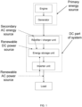
- Fig. 1 shows a schematic overview of one embodiment of the presently disclosed hybrid generator system, an embodiment where the primary energy source is a traditional combustion engine + a generator, the engine drives the generator and the generator converts the engine's mechanical energy to electrical energy (AC).
- the charger/rectifier unit converts the power from AC to DC, charges the battery and ensures the current does not run "backwards" towards the generator.
- the energy storage unit in the form of a battery unit battery stores the electrical energy.
- An inverter unit converts the DC power from the battery to grid-like AC power, e.g. 50 Hz or 60 Hz, 220/240/400 V AC.
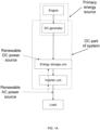
- Fig. 1A is similar to fig. 1 , but with a DC generator replacing the AC generator + rectifier.
- Fig. 1A shows a schematic overview of one embodiment of the presently disclosed hybrid generator system, an embodiment where the primary energy source is a traditional combustion engine + a DC generator, the engine drives the DC generator and the generator converts the engine's mechanical energy to electrical energy (DC).
- the DC power output can charge the battery directly, i.e. no need for a rectifier unit.
- the energy storage unit in the form of a battery unit battery stores the electrical energy.
- An inverter unit converts the DC power from the battery to grid-like AC power, e.g. 50 Hz or 60 Hz, 220/240/400 V AC.
- the load is the "client", e.g. an off-grid wind turbine under construction, that receives the power.
- the load is specified with a peak power requirement and a normal mode requirement and possibly an idle mode requirement and the presently disclosed hybrid generator is typically specified / configured to match those load requirements.
- the DC parts of the presently disclosed hybrid generator system form a major part of the system.
- an AC generator it is the rectifier unit, the energy storage unit and the inverter unit (even though the rectifier unit has an AC input and the inverter unit has an AC side), in case of a DC generator even more components are DC, such that most of the internal electrical connections can be low-voltage DC, i.e. quite safe.
- a secondary AC source can be connected to the rectifier unit, a renewable DC power source can be connected via the DC side of the rectifier unit and a renewable AC power source can be connected to the AC side of the inverter unit. Surplus power from the renewable AC power source can be routed to the rechargeable energy storage unit via the inverter.
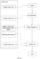
- Controllers are usually an integral part of the presently disclosed hybrid generator system, in figs. 2 and 2A illustrated as a control unit but in practice it is a plurality of separate controllers, e.g. an engine control unit for starting and stopping the engine, a control unit for controlling the charging of the energy storage unit, a battery control unit in the form of a BMS (battery management system), a BMS extender module and an inverter control unit for controlling the inverter and thereby controlling and monitoring the output to the load.
- BMS battery management system
- BMS battery management system
- BMS battery management system
- inverter control unit for controlling the inverter and thereby controlling and monitoring the output to the load.
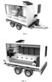
- Fig. 3 the housing mounted on a trailer showing the engine + generator side of one embodiment of the presently disclosed hybrid generator system.
- the housing is built in thermoplastic in the form of high density PE.
- the engine is visible inside the housing and the fuel tank is integrated in the housing below, and separated from, the engine.
- Fig. 4 shows the opposite part of the embodiment of fig. 3 showing the inverter + battery unit side of the housing.
- the modularized inverter unit with four visible 10 kVA inverter modules, is hanging on the wall and a modularized LTO battery unit is located in the bottom of the housing.
- figs. 3 and 4 The embodiment of figs. 3 and 4 is shown from the top in fig. 5 , where it can be seen the housing is split in two "compartments", one compartment (top in fig. 5 ) for the engine + generator and one compartment (bottom in fig. 5 ) for the inverter modules + battery modules.
- the four 10 kVA inverter modules visible in fig. 4 are also visible in fig. 5 along with five additional 10 kVA inverter modules hanging parallel to the first four 10 kVA inverter modules providing a 90 kVA inverter unit.
Landscapes
- Engineering & Computer Science (AREA)
- Power Engineering (AREA)
- Charge And Discharge Circuits For Batteries Or The Like (AREA)
- Hybrid Electric Vehicles (AREA)
- Control Of Eletrric Generators (AREA)
- Electric Propulsion And Braking For Vehicles (AREA)
- Control Of Charge By Means Of Generators (AREA)
Applications Claiming Priority (3)
| Application Number | Priority Date | Filing Date | Title |
|---|---|---|---|
| EP20204351 | 2020-10-28 | ||
| EP21802306.7A EP4238202B1 (de) | 2020-10-28 | 2021-10-28 | Mobiles hybridgeneratorsystem zur bereitstellung elektrischer energie |
| PCT/EP2021/080066 WO2022090432A1 (en) | 2020-10-28 | 2021-10-28 | Mobile hybrid generator system for providing electrical power |
Related Parent Applications (1)
| Application Number | Title | Priority Date | Filing Date |
|---|---|---|---|
| EP21802306.7A Division EP4238202B1 (de) | 2020-10-28 | 2021-10-28 | Mobiles hybridgeneratorsystem zur bereitstellung elektrischer energie |
Publications (2)
| Publication Number | Publication Date |
|---|---|
| EP4472011A2 true EP4472011A2 (de) | 2024-12-04 |
| EP4472011A3 EP4472011A3 (de) | 2025-03-12 |
Family
ID=73037781
Family Applications (2)
| Application Number | Title | Priority Date | Filing Date |
|---|---|---|---|
| EP21802306.7A Active EP4238202B1 (de) | 2020-10-28 | 2021-10-28 | Mobiles hybridgeneratorsystem zur bereitstellung elektrischer energie |
| EP24194118.6A Pending EP4472011A3 (de) | 2020-10-28 | 2021-10-28 | Mobiles hybridgeneratorsystem zur bereitstellung von strom |
Family Applications Before (1)
| Application Number | Title | Priority Date | Filing Date |
|---|---|---|---|
| EP21802306.7A Active EP4238202B1 (de) | 2020-10-28 | 2021-10-28 | Mobiles hybridgeneratorsystem zur bereitstellung elektrischer energie |
Country Status (13)
| Country | Link |
|---|---|
| US (1) | US12592569B2 (de) |
| EP (2) | EP4238202B1 (de) |
| JP (1) | JP2023551106A (de) |
| CN (1) | CN116670963A (de) |
| AU (1) | AU2021372798A1 (de) |
| CL (1) | CL2023001226A1 (de) |
| DK (3) | DK4238202T3 (de) |
| ES (1) | ES2994082T3 (de) |
| FI (1) | FI4238202T3 (de) |
| HU (1) | HUE069057T2 (de) |
| LT (1) | LT4238202T (de) |
| MX (1) | MX2023004993A (de) |
| WO (1) | WO2022090432A1 (de) |
Families Citing this family (4)
| Publication number | Priority date | Publication date | Assignee | Title |
|---|---|---|---|---|
| CN117465212A (zh) * | 2023-11-01 | 2024-01-30 | 山东浪潮新基建科技有限公司 | 一种基于行驶载具的驱动供电储能系统 |
| US20250292306A1 (en) * | 2024-03-13 | 2025-09-18 | Toyota Motor North America, Inc. | Electric vehicle recommendation based on home energy usage |
| BE1032770B1 (nl) | 2024-07-12 | 2026-02-09 | Europower Generators | Verbeterde generatie met invertor |
| US12463259B1 (en) | 2025-01-10 | 2025-11-04 | Enginuity Power Systems, Inc. | Integrated and compact combined heat and power systems and related methods |
Citations (1)
| Publication number | Priority date | Publication date | Assignee | Title |
|---|---|---|---|---|
| WO2019014691A1 (de) | 2017-07-20 | 2019-01-24 | Xelectrix Power Gmbh | Stromversorgungsanlage sowie raupenfahrzeug |
Family Cites Families (20)
| Publication number | Priority date | Publication date | Assignee | Title |
|---|---|---|---|---|
| JPS585073Y2 (ja) * | 1979-04-17 | 1983-01-28 | 澤藤電機株式会社 | 可搬式エンジン発電機 |
| WO2002015255A1 (en) | 2000-08-11 | 2002-02-21 | Chem Trace Corporation | System and method for cleaning semiconductor fabrication equipment parts |
| US6644247B2 (en) * | 2001-08-08 | 2003-11-11 | General Electric Company | Frequency switching systems for portable power modules |
| US7105940B2 (en) | 2004-03-31 | 2006-09-12 | General Electric Company | Mobile renewable energy generator |
| US7119450B2 (en) * | 2004-06-01 | 2006-10-10 | Illinois Tool Works Inc. | Fuel saving engine driven aircraft ground power device and method of use |
| CN101102050A (zh) * | 2006-02-02 | 2008-01-09 | 密尔沃基电动工具公司 | 发电系统及其方法 |
| US7834478B2 (en) * | 2006-12-05 | 2010-11-16 | Paul Baumann | Single- or dual-inverter auxiliary power conversion apparatus and system and narrow-hysteresis charging method |
| DE102008043205A1 (de) | 2008-10-27 | 2010-04-29 | Robert Bosch Gmbh | Energieerzeugungsvorrichtung zum mobilen Versorgen eines Fahrzeuges mit elektrischer Energie |
| JP2010106698A (ja) * | 2008-10-28 | 2010-05-13 | Yanmar Co Ltd | エンジン発電機 |
| JP5555125B2 (ja) * | 2010-10-13 | 2014-07-23 | 大阪瓦斯株式会社 | 発電システム |
| US8994214B2 (en) * | 2011-08-09 | 2015-03-31 | Bae Systems Controls Inc. | Hybrid electric generator set |
| GB201215564D0 (en) | 2012-08-31 | 2012-10-17 | Grid Energy The Ltd | Mobile electrical power module |
| US20140277791A1 (en) | 2013-03-15 | 2014-09-18 | Planetary Power, Inc. | Hybrid generator |
| US11444464B1 (en) * | 2016-03-25 | 2022-09-13 | Goal Zero Llc | Portable hybrid generator |
| US10389121B1 (en) * | 2016-11-02 | 2019-08-20 | Raymond C. Sherry | Efficient portable AC/DC power generator system |
| JP6695784B2 (ja) * | 2016-11-28 | 2020-05-20 | 株式会社日立製作所 | 発電システム |
| CN111164791A (zh) | 2017-10-06 | 2020-05-15 | Cps科技控股有限公司 | 用于接合电池模块中的热塑性部件的方法 |
| US10790670B1 (en) * | 2018-03-08 | 2020-09-29 | Zerobase Energy, Llc | Hybrid generator system and method with multi tasked power inverter |
| JP3223682U (ja) * | 2019-08-09 | 2019-10-24 | 株式会社ダイシン | 交流発電ユニット |
| US12283843B2 (en) * | 2019-09-06 | 2025-04-22 | Blue Power Systems, Inc. | Back-up generator and associated electric power systems |
-
2021
- 2021-10-28 AU AU2021372798A patent/AU2021372798A1/en active Pending
- 2021-10-28 ES ES21802306T patent/ES2994082T3/es active Active
- 2021-10-28 WO PCT/EP2021/080066 patent/WO2022090432A1/en not_active Ceased
- 2021-10-28 JP JP2023527027A patent/JP2023551106A/ja active Pending
- 2021-10-28 US US18/250,561 patent/US12592569B2/en active Active
- 2021-10-28 EP EP21802306.7A patent/EP4238202B1/de active Active
- 2021-10-28 DK DK21802306.7T patent/DK4238202T3/da active
- 2021-10-28 LT LTEPPCT/EP2021/080066T patent/LT4238202T/lt unknown
- 2021-10-28 FI FIEP21802306.7T patent/FI4238202T3/fi active
- 2021-10-28 HU HUE21802306A patent/HUE069057T2/hu unknown
- 2021-10-28 MX MX2023004993A patent/MX2023004993A/es unknown
- 2021-10-28 CN CN202180087816.0A patent/CN116670963A/zh active Pending
- 2021-10-28 EP EP24194118.6A patent/EP4472011A3/de active Pending
-
2023
- 2023-04-27 CL CL2023001226A patent/CL2023001226A1/es unknown
-
2024
- 2024-01-15 DK DKBA202400008U patent/DK202400008Y3/da active IP Right Grant
- 2024-05-31 DK DKBA202400041U patent/DK202400041U1/da not_active Application Discontinuation
Patent Citations (1)
| Publication number | Priority date | Publication date | Assignee | Title |
|---|---|---|---|---|
| WO2019014691A1 (de) | 2017-07-20 | 2019-01-24 | Xelectrix Power Gmbh | Stromversorgungsanlage sowie raupenfahrzeug |
Also Published As
| Publication number | Publication date |
|---|---|
| AU2021372798A1 (en) | 2023-06-01 |
| DK202400041U1 (da) | 2024-06-21 |
| EP4472011A3 (de) | 2025-03-12 |
| EP4238202B1 (de) | 2024-08-14 |
| HUE069057T2 (hu) | 2025-02-28 |
| JP2023551106A (ja) | 2023-12-07 |
| MX2023004993A (es) | 2023-07-24 |
| DK202400008U1 (da) | 2024-01-23 |
| US12592569B2 (en) | 2026-03-31 |
| DK202400008Y3 (da) | 2024-03-13 |
| LT4238202T (lt) | 2024-12-10 |
| CN116670963A (zh) | 2023-08-29 |
| CL2023001226A1 (es) | 2023-12-11 |
| WO2022090432A1 (en) | 2022-05-05 |
| US20230411968A1 (en) | 2023-12-21 |
| FI4238202T3 (fi) | 2024-11-14 |
| DK4238202T3 (da) | 2024-08-19 |
| EP4238202A1 (de) | 2023-09-06 |
| ES2994082T3 (en) | 2025-01-17 |
Similar Documents
| Publication | Publication Date | Title |
|---|---|---|
| US12592569B2 (en) | Mobile hybrid generator system for providing electrical power | |
| CA2377930C (en) | Hybrid battery/gas turbine locomotive | |
| RU2411143C2 (ru) | Гибридный локомотив с несколькими двигателями | |
| US6326763B1 (en) | System for controlling power flow in a power bus generally powered from reformer-based fuel cells | |
| US8569906B2 (en) | Energy supply system for supplying energy to aircraft systems | |
| CN102015354B (zh) | 推进系统 | |
| US6127798A (en) | Electric power supply having two electrical battery storage means for vehicles and other applications | |
| US9050897B1 (en) | Modification power system kit for existing vehicle | |
| US20230294506A1 (en) | Integrated electrical power generation methods and systems | |
| US20100206646A1 (en) | Oxyhydrogen vehicle | |
| US11677263B2 (en) | Off grid power supply system | |
| US12283822B2 (en) | Hybrid energy systems | |
| JP2024504732A (ja) | 電力供給システム、車両、電力変換システムおよび方法 | |
| US20210170873A1 (en) | Power supply systems and methods for vehicles | |
| JP2007022211A (ja) | 車両用電源装置 | |
| KR102704724B1 (ko) | 수소연료전지 선박용 전력 제어 시스템 | |
| US20230211688A1 (en) | Charging pole | |
| WO2022253831A1 (en) | A portable power unit | |
| EP2221204B1 (de) | Knallgasfahrzeug | |
| AU5602101A (en) | Hybrid battery/gas turbine locomotive | |
| CN104564476A (zh) | 一种燃油发动机的启动系统及其电路 |
Legal Events
| Date | Code | Title | Description |
|---|---|---|---|
| PUAI | Public reference made under article 153(3) epc to a published international application that has entered the european phase |
Free format text: ORIGINAL CODE: 0009012 |
|
| STAA | Information on the status of an ep patent application or granted ep patent |
Free format text: STATUS: THE APPLICATION HAS BEEN PUBLISHED |
|
| AC | Divisional application: reference to earlier application |
Ref document number: 4238202 Country of ref document: EP Kind code of ref document: P |
|
| AK | Designated contracting states |
Kind code of ref document: A2 Designated state(s): AL AT BE BG CH CY CZ DE DK EE ES FI FR GB GR HR HU IE IS IT LI LT LU LV MC MK MT NL NO PL PT RO RS SE SI SK SM TR |
|
| REG | Reference to a national code |
Ref country code: DE Ref legal event code: R079 Free format text: PREVIOUS MAIN CLASS: H02J0003460000 Ipc: H02J0003380000 |
|
| PUAL | Search report despatched |
Free format text: ORIGINAL CODE: 0009013 |
|
| AK | Designated contracting states |
Kind code of ref document: A3 Designated state(s): AL AT BE BG CH CY CZ DE DK EE ES FI FR GB GR HR HU IE IS IT LI LT LU LV MC MK MT NL NO PL PT RO RS SE SI SK SM TR |
|
| RIC1 | Information provided on ipc code assigned before grant |
Ipc: H02J 3/46 20060101ALI20250205BHEP Ipc: H02J 3/38 20060101AFI20250205BHEP |
|
| STAA | Information on the status of an ep patent application or granted ep patent |
Free format text: STATUS: REQUEST FOR EXAMINATION WAS MADE |
|
| TPAC | Observations filed by third parties |
Free format text: ORIGINAL CODE: EPIDOSNTIPA |
|
| 17P | Request for examination filed |
Effective date: 20250509 |
|
| STAA | Information on the status of an ep patent application or granted ep patent |
Free format text: STATUS: EXAMINATION IS IN PROGRESS |
|
| 17Q | First examination report despatched |
Effective date: 20251212 |