EP4471990A1 - Radom und radarvorrichtung damit - Google Patents
Radom und radarvorrichtung damit Download PDFInfo
- Publication number
- EP4471990A1 EP4471990A1 EP23213345.4A EP23213345A EP4471990A1 EP 4471990 A1 EP4471990 A1 EP 4471990A1 EP 23213345 A EP23213345 A EP 23213345A EP 4471990 A1 EP4471990 A1 EP 4471990A1
- Authority
- EP
- European Patent Office
- Prior art keywords
- radome
- antenna
- radar device
- annular region
- center
- Prior art date
- Legal status (The legal status is an assumption and is not a legal conclusion. Google has not performed a legal analysis and makes no representation as to the accuracy of the status listed.)
- Pending
Links
Images


Classifications
-
- H—ELECTRICITY
- H01—ELECTRIC ELEMENTS
- H01Q—ANTENNAS, i.e. RADIO AERIALS
- H01Q15/00—Devices for reflection, refraction, diffraction or polarisation of waves radiated from an antenna, e.g. quasi-optical devices
- H01Q15/02—Refracting or diffracting devices, e.g. lens, prism
- H01Q15/08—Refracting or diffracting devices, e.g. lens, prism formed of solid dielectric material
-
- H—ELECTRICITY
- H01—ELECTRIC ELEMENTS
- H01Q—ANTENNAS, i.e. RADIO AERIALS
- H01Q1/00—Details of, or arrangements associated with, antennas
- H01Q1/40—Radiating elements coated with or embedded in protective material
-
- H—ELECTRICITY
- H01—ELECTRIC ELEMENTS
- H01Q—ANTENNAS, i.e. RADIO AERIALS
- H01Q1/00—Details of, or arrangements associated with, antennas
- H01Q1/42—Housings not intimately mechanically associated with radiating elements, e.g. radome
-
- H—ELECTRICITY
- H01—ELECTRIC ELEMENTS
- H01Q—ANTENNAS, i.e. RADIO AERIALS
- H01Q19/00—Combinations of primary active antenna elements and units with secondary devices, e.g. with quasi-optical devices, for giving the antenna a desired directional characteristic
- H01Q19/06—Combinations of primary active antenna elements and units with secondary devices, e.g. with quasi-optical devices, for giving the antenna a desired directional characteristic using refracting or diffracting devices, e.g. lens
-
- H—ELECTRICITY
- H01—ELECTRIC ELEMENTS
- H01Q—ANTENNAS, i.e. RADIO AERIALS
- H01Q9/00—Electrically-short antennas having dimensions not more than twice the operating wavelength and consisting of conductive active radiating elements
- H01Q9/04—Resonant antennas
- H01Q9/0485—Dielectric resonator antennas
Definitions
- the present disclosure relates to a radome and a radar device using the radome, and particularly to a radome having a wavy surface and varying thickness and a radar device using the radome.
- the array antenna has advantages of compact size, high reliability and multibeam applicability.
- the array antenna is widely applied to various high-tech products.
- a modern satellite usually adopts an array antenna as major antenna structure.
- the array antenna transmits and receives wireless signals through beams with a narrow beam width.
- the signals fallen outside the coverage of the narrow beam width are probably subject to signal distortion or loss. Therefore, when an array antenna is used to transmit signals, it is necessary to increase the quantity of ground stations or transmitting/receiving field of view to ensure good satellite communication in all weathers.
- the technology of increasing either of the quantity and the transmitting/receiving field of view of the ground stations requires much money or manpower. Therefore, the problem indeed obstructs the development of satellite communication.
- the disclosure provides a radome which can widen the beam width of the beams for wireless signals and a radar device using the radome.
- the beam width widened by the radome can enlarge the field of view of the radar device.
- An aspect of the present disclosure provides a radome.
- the radome is made of a dielectric material. A thickness of the dielectric material is first increased and then decreased along a radial direction extending from a center to an outer edge of the radome.
- the radome has a first outer surface and a second outer surface opposite to each other.
- the first outer surface is a flat surface and the second outer surface first gets farther from the first outer surface and then gets closer to the first outer surface along the radial direction extending from the center to the outer edge of the radome.
- the second outer surface could show stepwise changes.
- a radar device including an antenna and a radome. There is a predetermined distance between the antenna and a center of the radome.
- the antenna transmits or receives electromagnetic waves passing through the radome.
- the radome is made of a dielectric material. A thickness of the dielectric material is first increased and then decreased along a radial direction extending from the center to an outer edge of the radome.
- the radome has a first outer surface and a second outer surface opposite to each other.
- the first outer surface is a flat surface and the second outer surface first gets farther from the first outer surface and then gets closer to the first outer surface along the radial direction extending from the center to the outer edge of the radome. Further, the second outer surface could show stepwise changes.
- the first outer surface faces towards the antenna.
- the radome has a wavy surface and varying thickness to adjust the phase retardation of electromagnetic waves emitted to the radome.
- the electromagnetic waves emitted to different portions of the radome are refracted with different refraction angles to achieve divergence effect. Therefore, if a radar device adopts the radome of the present disclosure, the electromagnetic waves passing through the random diverge due to the widened beam width. Hence, the radar device has larger transmission coverage during transmission of the electromagnetic waves, and has a larger receiving angle during reception of the electromagnetic waves.
- FIG. 1 is a top view of a radome according to an embodiment of the present disclosure
- FIG. 2 is cross-sectional view of the radome along the line AA' of FIG. 1
- the radome 10 is integrally formed of a single dielectric material, and includes a central region 100 and several annular regions 102-118. For illustration purposes, imagined boundaries are shown between any two adjacent regions, but the regions are not actually separate from each other.
- the central region 100 is located at the center of the radome 10, the annular region 102 is immediately adjacent to and surrounds the central region 100, the annular region 104 is immediately adjacent to and surrounds the annular region 102, the annular region 106 is immediately adjacent to and surrounds the annular region 104, the annular region 108 is immediately adjacent to and surrounds the annular region 106, the annular region 110 is immediately adjacent to and surrounds the annular region 108, the annular region 112 is immediately adjacent to and surrounds the annular region 110, the annular region 114 is immediately adjacent to and surrounds the annular region 112, the annular region 116 is immediately adjacent to and surrounds the annular region 114, and the annular region 118 is immediately adjacent to and surrounds the annular region 116.
- the present disclosure adjusts the thickness of the radome which is first increased and then decreased along the radially outward direction D (i.e. along a radial direction extending from a center C to the circumference/outer edge 10A of the radome 10). As shown in FIG. 2 , in the section between the central region 100 and the annular region 110, the radome 10 becomes thicker and thicker along the radially outward direction D.
- the annular region 102 is thicker than the central region 100
- the annular region 104 is thicker than the annular region 102
- the annular region 106 is thicker than the annular region 104
- the annular region 108 is thicker than the annular region 106
- the annular region 110 is thicker than the annular region 108.
- the radome 10 becomes thinner and thinner along the radially outward direction D.
- the annular region 112 is thinner than the annular region 110, the annular region 114 is thinner than the annular region 112, the annular region 116 is thinner than the annular region 114, and the annular region 118 is thinner than the annular region 116.
- the thickest portion is an annular block located between the center C and the circumference/outer edge 10A of the radome 10, and the radome 10 gets thinner and thinner from the thickest portion towards the center C and the circumference/outer edge 10A of the radome 10, respectively.
- the thickness of the radome 10 is adjusted by forming the radome 10 having an outer surface 150A (called the first outer surface hereinafter) and another outer surface 150B (called the second outer surface hereinafter) opposite to the first outer surface 150A with special design.
- the first outer surface 150A is a flat surface
- the second outer surface 150B is an undulant surface corresponding to the thickness distribution as described above.
- the second outer surface 150B gets closer to the first outer surface 150A when the corresponding distance between the center and the annular region of the radome 10 is longer.
- the second outer surface 150B may show stepwise changes or gradual changes.
- both outer surfaces of the radome 10 are stepwise surfaces in appearance. Such design is applicable without adverse effect.
- the size and quantity of the regions (e.g. regions 100-118) of the radome 10 are not limited to the embodiment and are adjustable to meet different requirements. Such adjustment involved in the design requires calculation of the parameters of respective regions, but makes the applications feasible.
- the circular radome described in the embodiment is just for illustration, but does not limit the shape of the radome.
- the thickness of the radome is first increased and then decreased along a radial direction extending from the center to the outer edge of the radome.
- the regions may be annular regions or not.
- the imagined boundaries shown between any two adjacent regions are in a shape of circle or not according to the shape of the radome.
- the thickness of each region should be properly designed.
- the calculation is based on the generalized laws of refraction.
- the angle of refraction of each region should be calculated to fit the desired divergence effect of the radome.
- the phase retardation corresponding to the angle of refraction of each region is calculated.
- the thickness of each region corresponding to the phase retardation is obtained.
- FIG. 3 is a schematic diagram illustrating a radar device according to an embodiment of the present disclosure.
- the radar device 20 includes an antenna 22 and the above described radome 10.
- the radome 10 is disposed above the antenna 22 with a distance d, and the antenna 22 transmits or receives the electromagnetic waves passing through the radome 10. It is known that the thickness of each region of the radome 10 further depends on the dielectric material of the radome 10 and the frequency of the electromagnetic waves received or transmitted through the radome 10. The obtained parameters are given below for reference.
- the radome 10 is designed to cooperate with the antenna 22 for K U band receiver at the frequency range of 10.7 GHz ⁇ 12.7 GHz.
- the radome 10 is made of a dielectric material having a dielectric constant about 2.72.
- the first outer surface 150A of the radome 10 faces towards the antenna 22 and the radome 10 is disposed at 20 cm above the antenna 22.
- FIG. 4 An example of the design parameters of the radome 10 obtained from the above concepts is shown in FIG. 4 .
- the radius indicates that the longest distance between the region and the center of the radome 10.
- the central region 100 is a circular block being concentric with the radome 10 and having a radius of 17.498 mm and a thickness of 2.73 mm
- the annular region 102 is an annular block being concentric with the radome 10 and having an outer radius of 35.265 mm, an inner radius of 17.498 mm and a thickness of 3.41 mm
- the annular region 104 is an annular block being concentric with the radome 10 and having an outer radius of 53.69 mm, an inner radius of 35.265 mm and a thickness of 5.07 mm, and so forth.
- the configurations of other similar regions can be derived from FIG. 4 , and need not be further described herein.
- FIG. 5 shows peak gain and half-power beam width (HPBW) of an uncovered antenna measured in the TE mode
- FIG. 6 shows peak gain and half-power beam width of a radar device, including the radome in FIG. 4 and the antenna in FIG. 5 , measured in the TE mode
- FIG. 7 shows peak gain and half-power beam width of the uncovered antenna measured in the TM mode
- FIG. 8 shows peak gain and half-power beam width of the radar device, including the radome in FIG. 4 and the antenna in FIG. 5 , measured in the TM mode.
- the half-power beam width of the radar device 20 in this embodiment is increased significantly.
- the radome of the present disclosure indeed increases the beam width of the electromagnetic waves to achieve divergence effect.
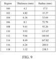
- the radome 10 is designed to cooperate with the antenna 22 for K U band transmitter at the frequency range of 14 GHz ⁇ 14.5 GHz.
- the radome 10 is also made of a dielectric material having a dielectric constant about 2.72.
- the first outer surface 150A of the radome 10 faces towards the antenna 22 and the radome 10 is disposed at 20 cm above the antenna 22.
- FIG. 9 An example of the design parameters of the radome 10 obtained from the above concepts is shown in FIG. 9 .
- the meaning of the parameters is similar to those described in the embodiment with reference to FIG. 4 , and needs not be further explained.
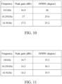
- FIGS. 10 and 12 show peak gain and half-power beam width of the electromagnetic waves emitted by the uncovered antenna; and FIGS. 11 and 13 show peak gain and half-power beam width of the electromagnetic waves emitted by the radar device including the radome in FIG. 9 cooperating with the same antenna used in FIGS. 10 and 12 .
- the half-power beam width of the radar device 20 in this embodiment is increased significantly.
- the radome of the present disclosure indeed increases the beam width of the electromagnetic waves to achieve divergence effect.
- the radome of the present disclosure has a wavy surface and varying thickness to adjust the phase retardation of electromagnetic waves emitted to the radome.
- the electromagnetic waves emitted to different portions of the radome are refracted with different refraction angles to achieve divergence effect. Therefore, if a radar device adopts the radome of the present disclosure, the electromagnetic waves passing through the random diverge due to the widened beam width. Hence, the radar device has larger transmission coverage during transmission of the electromagnetic waves, and has a larger receiving angle during reception of the electromagnetic waves.
Landscapes
- Details Of Aerials (AREA)
Applications Claiming Priority (1)
| Application Number | Priority Date | Filing Date | Title |
|---|---|---|---|
| TW112120381A TWI863321B (zh) | 2023-05-31 | 2023-05-31 | 天線罩及使用其的雷達 |
Publications (1)
| Publication Number | Publication Date |
|---|---|
| EP4471990A1 true EP4471990A1 (de) | 2024-12-04 |
Family
ID=89029925
Family Applications (1)
| Application Number | Title | Priority Date | Filing Date |
|---|---|---|---|
| EP23213345.4A Pending EP4471990A1 (de) | 2023-05-31 | 2023-11-30 | Radom und radarvorrichtung damit |
Country Status (3)
| Country | Link |
|---|---|
| US (1) | US12451599B2 (de) |
| EP (1) | EP4471990A1 (de) |
| TW (1) | TWI863321B (de) |
Citations (6)
| Publication number | Priority date | Publication date | Assignee | Title |
|---|---|---|---|---|
| US5121129A (en) * | 1990-03-14 | 1992-06-09 | Space Systems/Loral, Inc. | EHF omnidirectional antenna |
| JPH09191212A (ja) * | 1996-01-09 | 1997-07-22 | Murata Mfg Co Ltd | 誘電体レンズおよびその製造方法 |
| US20090047023A1 (en) * | 2004-11-15 | 2009-02-19 | Christopher Ralph Pescod | Data communications system |
| GB2510885A (en) * | 2013-02-18 | 2014-08-20 | Bae Systems Plc | Integrated lighting and network interface device |
| US20190326676A1 (en) * | 2018-04-23 | 2019-10-24 | Sharp Kabushiki Kaisha | High-frequency apparatus |
| CN113285235A (zh) * | 2021-06-30 | 2021-08-20 | 中国电子科技集团公司第五十四研究所 | 一种宽波束透镜天线 |
Family Cites Families (14)
| Publication number | Priority date | Publication date | Assignee | Title |
|---|---|---|---|---|
| US3314070A (en) * | 1959-04-30 | 1967-04-11 | Fred R Youngren | Tapered radomes |
| JPH01143506A (ja) * | 1987-11-30 | 1989-06-06 | Sony Corp | 平面アンテナ |
| JP2757013B2 (ja) * | 1989-05-15 | 1998-05-25 | 株式会社トキメック | レドーム |
| US8184064B2 (en) * | 2009-09-16 | 2012-05-22 | Ubiquiti Networks | Antenna system and method |
| JP5555087B2 (ja) * | 2010-07-30 | 2014-07-23 | 株式会社豊田中央研究所 | レーダ装置 |
| CN102723597B (zh) * | 2012-05-30 | 2015-02-04 | 深圳光启创新技术有限公司 | 超材料天线罩及天线系统 |
| US9985347B2 (en) * | 2013-10-30 | 2018-05-29 | Commscope Technologies Llc | Broad band radome for microwave antenna |
| CN203787560U (zh) * | 2014-01-16 | 2014-08-20 | 西安希德电子信息技术有限公司 | 一种北斗导航接收设备手持机天线 |
| KR102532360B1 (ko) * | 2018-12-28 | 2023-05-16 | 생-고뱅 퍼포먼스 플라스틱스 코포레이션 | 연속 유전율 적응 레이돔 설계 |
| DE102019200912A1 (de) * | 2019-01-24 | 2020-07-30 | Robert Bosch Gmbh | Radombaugruppe für einen Radarsensor für Kraftfahrzeuge |
| CN110380208B (zh) * | 2019-07-03 | 2021-02-05 | 惠州市德赛西威智能交通技术研究院有限公司 | 一种变厚度双弧形毫米波雷达天线罩及设计方法 |
| CN110444883A (zh) * | 2019-07-26 | 2019-11-12 | 中国航空工业集团公司济南特种结构研究所 | 一种采用泡沫过渡结构的多夹层蜂窝结构天线罩 |
| CN113036421A (zh) * | 2019-12-09 | 2021-06-25 | 康普技术有限责任公司 | 用于基站天线的天线罩及基站天线 |
| CN112490658B (zh) * | 2020-11-09 | 2022-03-29 | 曲阜师范大学 | 一种曲面共形频率选择表面天线罩 |
-
2023
- 2023-05-31 TW TW112120381A patent/TWI863321B/zh active
- 2023-11-30 US US18/523,955 patent/US12451599B2/en active Active
- 2023-11-30 EP EP23213345.4A patent/EP4471990A1/de active Pending
Patent Citations (6)
| Publication number | Priority date | Publication date | Assignee | Title |
|---|---|---|---|---|
| US5121129A (en) * | 1990-03-14 | 1992-06-09 | Space Systems/Loral, Inc. | EHF omnidirectional antenna |
| JPH09191212A (ja) * | 1996-01-09 | 1997-07-22 | Murata Mfg Co Ltd | 誘電体レンズおよびその製造方法 |
| US20090047023A1 (en) * | 2004-11-15 | 2009-02-19 | Christopher Ralph Pescod | Data communications system |
| GB2510885A (en) * | 2013-02-18 | 2014-08-20 | Bae Systems Plc | Integrated lighting and network interface device |
| US20190326676A1 (en) * | 2018-04-23 | 2019-10-24 | Sharp Kabushiki Kaisha | High-frequency apparatus |
| CN113285235A (zh) * | 2021-06-30 | 2021-08-20 | 中国电子科技集团公司第五十四研究所 | 一种宽波束透镜天线 |
Non-Patent Citations (2)
| Title |
|---|
| PENGFEI ZHANGSHUXI GONGRAJ MITTRA: "Beam-Shaping Technique Based on Generalized Laws of Refraction and Reflection", IEEE TRANSACTIONS ON ANTENNAS AND PROPAGATION, vol. 66, 2018, pages 771 - 779, XP011676737, DOI: 10.1109/TAP.2017.2778042 |
| ZHENGBIN WANGJ. SHIJIN-CHANG CHEN: "High-Efficiency Electromagnetic Wave Controlling with All-Dielectric Huygens' Metasurfaces", INTERNATIONAL JOURNAL OF ANTENNAS AND PROPAGATION, 2015, pages 1 - 7 |
Also Published As
| Publication number | Publication date |
|---|---|
| TW202450179A (zh) | 2024-12-16 |
| US12451599B2 (en) | 2025-10-21 |
| TWI863321B (zh) | 2024-11-21 |
| US20240405415A1 (en) | 2024-12-05 |
Similar Documents
| Publication | Publication Date | Title |
|---|---|---|
| US10224638B2 (en) | Lens antenna | |
| EP2912719B1 (de) | Kommunikationsanordnung | |
| US8193994B2 (en) | Millimeter-wave chip-lens array antenna systems for wireless networks | |
| US6606057B2 (en) | High gain planar scanned antenna array | |
| US10727607B2 (en) | Horn antenna | |
| US4673943A (en) | Integrated defense communications system antijamming antenna system | |
| US6429826B2 (en) | Arrangement relating to reflector antennas | |
| CN114520418B (zh) | 具有非对称辐射图案的双极化喇叭天线 | |
| US4263599A (en) | Parabolic reflector antenna for telecommunication system | |
| KR102015530B1 (ko) | 평면형 반사판을 포함하는 모노펄스 안테나 | |
| EP4471990A1 (de) | Radom und radarvorrichtung damit | |
| US20250279574A1 (en) | Dual-polarized antenna element, antenna apparatus, and base station system | |
| US9196967B2 (en) | Beamwidth adjustment device | |
| CN110444867B (zh) | 一种圆极化贴片天线 | |
| US7262741B2 (en) | Ultra wideband antenna | |
| US11791562B2 (en) | Ring focus antenna system with an ultra-wide bandwidth | |
| US7333070B2 (en) | Radio wave lens antenna device | |
| KR101727961B1 (ko) | 위성신호 통신 장치 | |
| EP4471987A1 (de) | Radom mit metallmustern verschiedener grösse und radarvorrichtung damit | |
| US12040539B2 (en) | Mitigation of ripple in element pattern of geodesic antenna | |
| HK40068029A (en) | Dual polarized horn antenna with asymmetric radiation pattern | |
| KR102023959B1 (ko) | 파라볼라 안테나 | |
| GB2639304A (en) | Electronic device | |
| JPH06112724A (ja) | 2周波共用電磁結合パッチアンテナ | |
| CN120280702A (zh) | 一种低副瓣的微波天线及其设计方法 |
Legal Events
| Date | Code | Title | Description |
|---|---|---|---|
| PUAI | Public reference made under article 153(3) epc to a published international application that has entered the european phase |
Free format text: ORIGINAL CODE: 0009012 |
|
| STAA | Information on the status of an ep patent application or granted ep patent |
Free format text: STATUS: REQUEST FOR EXAMINATION WAS MADE |
|
| 17P | Request for examination filed |
Effective date: 20231219 |
|
| AK | Designated contracting states |
Kind code of ref document: A1 Designated state(s): AL AT BE BG CH CY CZ DE DK EE ES FI FR GB GR HR HU IE IS IT LI LT LU LV MC ME MK MT NL NO PL PT RO RS SE SI SK SM TR |