EP4471504A1 - Bilderzeugungsgerät - Google Patents
Bilderzeugungsgerät Download PDFInfo
- Publication number
- EP4471504A1 EP4471504A1 EP24178612.8A EP24178612A EP4471504A1 EP 4471504 A1 EP4471504 A1 EP 4471504A1 EP 24178612 A EP24178612 A EP 24178612A EP 4471504 A1 EP4471504 A1 EP 4471504A1
- Authority
- EP
- European Patent Office
- Prior art keywords
- sheet
- image
- sensor
- conveyance
- image forming
- Prior art date
- Legal status (The legal status is an assumption and is not a legal conclusion. Google has not performed a legal analysis and makes no representation as to the accuracy of the status listed.)
- Granted
Links
Images


Classifications
-
- B—PERFORMING OPERATIONS; TRANSPORTING
- B65—CONVEYING; PACKING; STORING; HANDLING THIN OR FILAMENTARY MATERIAL
- B65H—HANDLING THIN OR FILAMENTARY MATERIAL, e.g. SHEETS, WEBS, CABLES
- B65H7/00—Controlling article feeding, separating, pile-advancing, or associated apparatus, to take account of incorrect feeding, absence of articles, or presence of faulty articles
- B65H7/02—Controlling article feeding, separating, pile-advancing, or associated apparatus, to take account of incorrect feeding, absence of articles, or presence of faulty articles by feelers or detectors
- B65H7/06—Controlling article feeding, separating, pile-advancing, or associated apparatus, to take account of incorrect feeding, absence of articles, or presence of faulty articles by feelers or detectors responsive to presence of faulty articles or incorrect separation or feed
-
- B—PERFORMING OPERATIONS; TRANSPORTING
- B65—CONVEYING; PACKING; STORING; HANDLING THIN OR FILAMENTARY MATERIAL
- B65H—HANDLING THIN OR FILAMENTARY MATERIAL, e.g. SHEETS, WEBS, CABLES
- B65H5/00—Feeding articles separated from piles; Feeding articles to machines
- B65H5/22—Feeding articles separated from piles; Feeding articles to machines by air-blast or suction device
- B65H5/222—Feeding articles separated from piles; Feeding articles to machines by air-blast or suction device by suction devices
- B65H5/224—Feeding articles separated from piles; Feeding articles to machines by air-blast or suction device by suction devices by suction belts
-
- G—PHYSICS
- G03—PHOTOGRAPHY; CINEMATOGRAPHY; ANALOGOUS TECHNIQUES USING WAVES OTHER THAN OPTICAL WAVES; ELECTROGRAPHY; HOLOGRAPHY
- G03G—ELECTROGRAPHY; ELECTROPHOTOGRAPHY; MAGNETOGRAPHY
- G03G15/00—Apparatus for electrographic processes using a charge pattern
- G03G15/22—Apparatus for electrographic processes using a charge pattern involving the combination of more than one step according to groups G03G13/02 - G03G13/20
- G03G15/23—Apparatus for electrographic processes using a charge pattern involving the combination of more than one step according to groups G03G13/02 - G03G13/20 specially adapted for copying both sides of an original or for copying on both sides of a recording or image-receiving material
- G03G15/231—Arrangements for copying on both sides of a recording or image-receiving material
- G03G15/232—Arrangements for copying on both sides of a recording or image-receiving material using a single reusable electrographic recording member
- G03G15/234—Arrangements for copying on both sides of a recording or image-receiving material using a single reusable electrographic recording member by inverting and refeeding the image receiving material with an image on one face to the recording member to transfer a second image on its second face, e.g. by using a duplex tray; Details of duplex trays or inverters
-
- B—PERFORMING OPERATIONS; TRANSPORTING
- B41—PRINTING; LINING MACHINES; TYPEWRITERS; STAMPS
- B41J—TYPEWRITERS; SELECTIVE PRINTING MECHANISMS, i.e. MECHANISMS PRINTING OTHERWISE THAN FROM A FORME; CORRECTION OF TYPOGRAPHICAL ERRORS
- B41J11/00—Devices or arrangements of selective printing mechanisms, e.g. ink-jet printers or thermal printers, for supporting or handling copy material in sheet or web form
- B41J11/008—Controlling printhead for accurately positioning print image on printing material, e.g. with the intention to control the width of margins
-
- B—PERFORMING OPERATIONS; TRANSPORTING
- B41—PRINTING; LINING MACHINES; TYPEWRITERS; STAMPS
- B41J—TYPEWRITERS; SELECTIVE PRINTING MECHANISMS, i.e. MECHANISMS PRINTING OTHERWISE THAN FROM A FORME; CORRECTION OF TYPOGRAPHICAL ERRORS
- B41J11/00—Devices or arrangements of selective printing mechanisms, e.g. ink-jet printers or thermal printers, for supporting or handling copy material in sheet or web form
- B41J11/0085—Using suction for maintaining printing material flat
-
- B—PERFORMING OPERATIONS; TRANSPORTING
- B41—PRINTING; LINING MACHINES; TYPEWRITERS; STAMPS
- B41J—TYPEWRITERS; SELECTIVE PRINTING MECHANISMS, i.e. MECHANISMS PRINTING OTHERWISE THAN FROM A FORME; CORRECTION OF TYPOGRAPHICAL ERRORS
- B41J11/00—Devices or arrangements of selective printing mechanisms, e.g. ink-jet printers or thermal printers, for supporting or handling copy material in sheet or web form
- B41J11/0095—Detecting means for copy material, e.g. for detecting or sensing presence of copy material or its leading or trailing end
-
- B—PERFORMING OPERATIONS; TRANSPORTING
- B41—PRINTING; LINING MACHINES; TYPEWRITERS; STAMPS
- B41J—TYPEWRITERS; SELECTIVE PRINTING MECHANISMS, i.e. MECHANISMS PRINTING OTHERWISE THAN FROM A FORME; CORRECTION OF TYPOGRAPHICAL ERRORS
- B41J13/00—Devices or arrangements of selective printing mechanisms, e.g. ink-jet printers or thermal printers, specially adapted for supporting or handling copy material in short lengths, e.g. sheets
- B41J13/08—Conveyor bands or like feeding devices
-
- B—PERFORMING OPERATIONS; TRANSPORTING
- B41—PRINTING; LINING MACHINES; TYPEWRITERS; STAMPS
- B41J—TYPEWRITERS; SELECTIVE PRINTING MECHANISMS, i.e. MECHANISMS PRINTING OTHERWISE THAN FROM A FORME; CORRECTION OF TYPOGRAPHICAL ERRORS
- B41J13/00—Devices or arrangements of selective printing mechanisms, e.g. ink-jet printers or thermal printers, specially adapted for supporting or handling copy material in short lengths, e.g. sheets
- B41J13/26—Registering devices
-
- B—PERFORMING OPERATIONS; TRANSPORTING
- B41—PRINTING; LINING MACHINES; TYPEWRITERS; STAMPS
- B41J—TYPEWRITERS; SELECTIVE PRINTING MECHANISMS, i.e. MECHANISMS PRINTING OTHERWISE THAN FROM A FORME; CORRECTION OF TYPOGRAPHICAL ERRORS
- B41J3/00—Typewriters or selective printing or marking mechanisms characterised by the purpose for which they are constructed
- B41J3/60—Typewriters or selective printing or marking mechanisms characterised by the purpose for which they are constructed for printing on both faces of the printing material
-
- B—PERFORMING OPERATIONS; TRANSPORTING
- B65—CONVEYING; PACKING; STORING; HANDLING THIN OR FILAMENTARY MATERIAL
- B65H—HANDLING THIN OR FILAMENTARY MATERIAL, e.g. SHEETS, WEBS, CABLES
- B65H5/00—Feeding articles separated from piles; Feeding articles to machines
- B65H5/06—Feeding articles separated from piles; Feeding articles to machines by rollers or balls, e.g. between rollers
- B65H5/062—Feeding articles separated from piles; Feeding articles to machines by rollers or balls, e.g. between rollers between rollers or balls
-
- B—PERFORMING OPERATIONS; TRANSPORTING
- B65—CONVEYING; PACKING; STORING; HANDLING THIN OR FILAMENTARY MATERIAL
- B65H—HANDLING THIN OR FILAMENTARY MATERIAL, e.g. SHEETS, WEBS, CABLES
- B65H5/00—Feeding articles separated from piles; Feeding articles to machines
- B65H5/36—Article guides or smoothers, e.g. movable in operation
-
- B—PERFORMING OPERATIONS; TRANSPORTING
- B65—CONVEYING; PACKING; STORING; HANDLING THIN OR FILAMENTARY MATERIAL
- B65H—HANDLING THIN OR FILAMENTARY MATERIAL, e.g. SHEETS, WEBS, CABLES
- B65H7/00—Controlling article feeding, separating, pile-advancing, or associated apparatus, to take account of incorrect feeding, absence of articles, or presence of faulty articles
- B65H7/02—Controlling article feeding, separating, pile-advancing, or associated apparatus, to take account of incorrect feeding, absence of articles, or presence of faulty articles by feelers or detectors
-
- B—PERFORMING OPERATIONS; TRANSPORTING
- B65—CONVEYING; PACKING; STORING; HANDLING THIN OR FILAMENTARY MATERIAL
- B65H—HANDLING THIN OR FILAMENTARY MATERIAL, e.g. SHEETS, WEBS, CABLES
- B65H9/00—Registering, e.g. orientating, articles; Devices therefor
- B65H9/002—Registering, e.g. orientating, articles; Devices therefor changing orientation of sheet by only controlling movement of the forwarding means, i.e. without the use of stop or register wall
-
- B—PERFORMING OPERATIONS; TRANSPORTING
- B65—CONVEYING; PACKING; STORING; HANDLING THIN OR FILAMENTARY MATERIAL
- B65H—HANDLING THIN OR FILAMENTARY MATERIAL, e.g. SHEETS, WEBS, CABLES
- B65H9/00—Registering, e.g. orientating, articles; Devices therefor
- B65H9/16—Inclined tape, roller, or like article-forwarding side registers
- B65H9/166—Roller
-
- G—PHYSICS
- G03—PHOTOGRAPHY; CINEMATOGRAPHY; ANALOGOUS TECHNIQUES USING WAVES OTHER THAN OPTICAL WAVES; ELECTROGRAPHY; HOLOGRAPHY
- G03G—ELECTROGRAPHY; ELECTROPHOTOGRAPHY; MAGNETOGRAPHY
- G03G15/00—Apparatus for electrographic processes using a charge pattern
- G03G15/50—Machine control of apparatus for electrographic processes using a charge pattern, e.g. regulating differents parts of the machine, multimode copiers, microprocessor control
-
- G—PHYSICS
- G03—PHOTOGRAPHY; CINEMATOGRAPHY; ANALOGOUS TECHNIQUES USING WAVES OTHER THAN OPTICAL WAVES; ELECTROGRAPHY; HOLOGRAPHY
- G03G—ELECTROGRAPHY; ELECTROPHOTOGRAPHY; MAGNETOGRAPHY
- G03G15/00—Apparatus for electrographic processes using a charge pattern
- G03G15/65—Apparatus which relate to the handling of copy material
- G03G15/6529—Transporting
-
- G—PHYSICS
- G03—PHOTOGRAPHY; CINEMATOGRAPHY; ANALOGOUS TECHNIQUES USING WAVES OTHER THAN OPTICAL WAVES; ELECTROGRAPHY; HOLOGRAPHY
- G03G—ELECTROGRAPHY; ELECTROPHOTOGRAPHY; MAGNETOGRAPHY
- G03G15/00—Apparatus for electrographic processes using a charge pattern
- G03G15/65—Apparatus which relate to the handling of copy material
- G03G15/6555—Handling of sheet copy material taking place in a specific part of the copy material feeding path
- G03G15/6558—Feeding path after the copy sheet preparation and up to the transfer point, e.g. registering; Deskewing; Correct timing of sheet feeding to the transfer point
- G03G15/6561—Feeding path after the copy sheet preparation and up to the transfer point, e.g. registering; Deskewing; Correct timing of sheet feeding to the transfer point for sheet registration
-
- G—PHYSICS
- G03—PHOTOGRAPHY; CINEMATOGRAPHY; ANALOGOUS TECHNIQUES USING WAVES OTHER THAN OPTICAL WAVES; ELECTROGRAPHY; HOLOGRAPHY
- G03G—ELECTROGRAPHY; ELECTROPHOTOGRAPHY; MAGNETOGRAPHY
- G03G15/00—Apparatus for electrographic processes using a charge pattern
- G03G15/65—Apparatus which relate to the handling of copy material
- G03G15/6555—Handling of sheet copy material taking place in a specific part of the copy material feeding path
- G03G15/6558—Feeding path after the copy sheet preparation and up to the transfer point, e.g. registering; Deskewing; Correct timing of sheet feeding to the transfer point
- G03G15/6567—Feeding path after the copy sheet preparation and up to the transfer point, e.g. registering; Deskewing; Correct timing of sheet feeding to the transfer point for deskewing or aligning
-
- G—PHYSICS
- G03—PHOTOGRAPHY; CINEMATOGRAPHY; ANALOGOUS TECHNIQUES USING WAVES OTHER THAN OPTICAL WAVES; ELECTROGRAPHY; HOLOGRAPHY
- G03G—ELECTROGRAPHY; ELECTROPHOTOGRAPHY; MAGNETOGRAPHY
- G03G15/00—Apparatus for electrographic processes using a charge pattern
- G03G15/70—Detecting malfunctions relating to paper handling, e.g. jams
-
- G—PHYSICS
- G03—PHOTOGRAPHY; CINEMATOGRAPHY; ANALOGOUS TECHNIQUES USING WAVES OTHER THAN OPTICAL WAVES; ELECTROGRAPHY; HOLOGRAPHY
- G03G—ELECTROGRAPHY; ELECTROPHOTOGRAPHY; MAGNETOGRAPHY
- G03G21/00—Arrangements not provided for by groups G03G13/00 - G03G19/00, e.g. cleaning, elimination of residual charge
- G03G21/16—Mechanical means for facilitating the maintenance of the apparatus, e.g. modular arrangements
- G03G21/1661—Mechanical means for facilitating the maintenance of the apparatus, e.g. modular arrangements means for handling parts of the apparatus in the apparatus
- G03G21/1695—Mechanical means for facilitating the maintenance of the apparatus, e.g. modular arrangements means for handling parts of the apparatus in the apparatus for paper transport
-
- B—PERFORMING OPERATIONS; TRANSPORTING
- B65—CONVEYING; PACKING; STORING; HANDLING THIN OR FILAMENTARY MATERIAL
- B65H—HANDLING THIN OR FILAMENTARY MATERIAL, e.g. SHEETS, WEBS, CABLES
- B65H2301/00—Handling processes for sheets or webs
- B65H2301/30—Orientation, displacement, position of the handled material
- B65H2301/33—Modifying, selecting, changing orientation
- B65H2301/331—Skewing, correcting skew, i.e. changing slightly orientation of material
-
- B—PERFORMING OPERATIONS; TRANSPORTING
- B65—CONVEYING; PACKING; STORING; HANDLING THIN OR FILAMENTARY MATERIAL
- B65H—HANDLING THIN OR FILAMENTARY MATERIAL, e.g. SHEETS, WEBS, CABLES
- B65H2553/00—Sensing or detecting means
- B65H2553/80—Arangement of the sensing means
-
- B—PERFORMING OPERATIONS; TRANSPORTING
- B65—CONVEYING; PACKING; STORING; HANDLING THIN OR FILAMENTARY MATERIAL
- B65H—HANDLING THIN OR FILAMENTARY MATERIAL, e.g. SHEETS, WEBS, CABLES
- B65H2701/00—Handled material; Storage means
- B65H2701/10—Handled articles or webs
- B65H2701/13—Parts concerned of the handled material
- B65H2701/131—Edges
- B65H2701/1311—Edges leading edge
-
- B—PERFORMING OPERATIONS; TRANSPORTING
- B65—CONVEYING; PACKING; STORING; HANDLING THIN OR FILAMENTARY MATERIAL
- B65H—HANDLING THIN OR FILAMENTARY MATERIAL, e.g. SHEETS, WEBS, CABLES
- B65H2701/00—Handled material; Storage means
- B65H2701/10—Handled articles or webs
- B65H2701/13—Parts concerned of the handled material
- B65H2701/131—Edges
- B65H2701/1313—Edges trailing edge
-
- B—PERFORMING OPERATIONS; TRANSPORTING
- B65—CONVEYING; PACKING; STORING; HANDLING THIN OR FILAMENTARY MATERIAL
- B65H—HANDLING THIN OR FILAMENTARY MATERIAL, e.g. SHEETS, WEBS, CABLES
- B65H2801/00—Application field
- B65H2801/03—Image reproduction devices
Definitions
- the present invention relates to print position control for adjusting an image formation position of an image to be formed on a sheet by an image forming apparatus.
- An image forming apparatus that forms images on sheets controlling conveyance positions of a sheet on which images are to be formed to be target positions, to align the positions of one image to be formed on the front surface of the sheet and the other image to be formed on the rear surface of the sheet.
- An image forming apparatus discussed in United States Patent Application Publication No. 2009/0134569 sets one side (will be referred to as a reference side) of a sheet as a reference, and controls the position of the sheet in a direction orthogonal to the conveyance direction in which the sheet is conveyed, in such a manner that the reference side reaches a target position.
- sheets have cutting errors in different manufacturing lots, producing differences in shape of sheets. Furthermore, the shape of sheets varies due to the environment (e.g., temperature and humidity) where the sheets are stored. Thus, with a sheet whose shape is different from an ideal rectangle, one reference side of the sheet set to form an image on the front surface and another reference side of the sheet set to form an image on the rear surface are not parallel.
- the image forming apparatus discussed in United States Patent Application Publication No. 2009/0134569 cannot accurately control relative positions of an image on the front surface and an image on the rear surface due to the shape of the sheet. With one reference side of a sheet set to form an image on the front surface and another reference side of the sheet set to form an image on the reverse surface not parallel, the image on the front surface and the image on the rear surface are not aligned.
- an image forming apparatus as specified in claims 1 to18.
- a computer program as specified in claim 20.
- a computer-readable data carrier as specified in claim 21.
- Fig. 1 is a schematic diagram illustrating an example of a schematic configuration of an inkjet recording apparatus.
- This inkjet recording apparatus is a cut sheet inkjet recording apparatus that forms ink images on sheets S using two types of liquid, reaction liquid and ink to manufacture recording products.
- the inkjet recording apparatus includes a sheet feeding module 1000, a print module 2000, a drying module 3000, a fixing module 4000, a cooling module 5000, a reversing module 6000, and a sheet discharging and stacking module 7000.
- Cut sheets hereinafter, will be referred to as the sheets S
- the sheets S are conveyed along a conveyance path, subjected to processing in modules, and discharged to the sheet discharging and stacking module 7000.
- the sheet feeding module 1000 includes three storages 1100a to 1100c storing the sheets S arranged.
- the storages 1 100a to 1 100c are drawable from the apparatus front surface.
- the sheets S are fed one by one from any of the storages 1 100a to 1 100c by the separation belt and the conveyance roller, and conveyed to the print module 2000.
- the number of the storages 1 100a to 1 100c is not limited to three, and can be one, two, or four or more.
- the print module 2000 includes a registration unit 2100 (not shown in Fig. 1 ), a print belt unit 2200, and a recording unit 2300.
- a registration unit 2100 (not shown in Fig. 1 )
- a print belt unit 2200 for example, a print belt
- a recording unit 2300 is arranged on the conveyance path at a position facing the print belt unit 2200.
- the recording unit 2300 functions as an image forming unit that forms images on the conveyed sheets S.
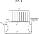
- the recording unit 2300 forms images on the sheets S with ink ejected by a recording head 10 ( Fig. 2 ) from above onto the conveyed sheets S.
- a recording head 10 Fig. 2
- Each of the sheets S is conveyed while being sucked by the print belt unit 2200, ensuring the clearance between the sheet S and the recording head 10 ( Fig. 2 ).
- a plurality of recording heads 10 are arranged in the conveyance direction.
- the print module 2000 includes five line-type recording heads that consists of reaction liquid added to four colors, yellow (Y), magenta (M), cyan (C), and black (Bk).
- Each line-type recording head includes a plurality of ink ejection ports arranged in its longer side direction.
- the number of colors and the number of recording heads 10 ( Fig. 2 ) are not limited to five. Examples of an inkjet method that can be employed include a method with a heater element, a method with a piezoelectric element, a method with an electrostatic element, or a method with a microelectromechanical system (MEMS) element.
- MEMS microelectromechanical system
- the ink of each color is supplied from the ink tank (not illustrated) to the recording head 10 ( Fig. 2 ) via the ink tube.
- Each of the sheets S on which an image is printed by the recording unit 2300 is conveyed by the print belt unit 2200, and read by an in-line scanner unit 1 ( Fig. 2 ) arranged in the conveyance direction downstream of the recording unit 2300.
- the inkjet recording apparatus can correct a subsequent image to be printed.
- the drying module 3000 is a unit that includes a decoupling unit 3200, a drying belt unit 3300, and a hot air blowing unit 3400 to decrease the liquid component contained in the ink on each of the sheets S applied by the recording unit 2300 to enhance the fixability of the sheet S and the ink.
- the hot air blowing unit 3400 of the drying module 3000 functions as a drying unit that dries an image on each of the sheets S.
- Each of the sheets S on which an image is printed by the recording unit 2300 of the print module 2000 is conveyed to the decoupling unit 3200 arranged in the drying module 3000.
- the sheet S can be conveyed using the pressure of air from above and the friction of a belt while being held on the belt, preventing shift of each of the sheets S on the belt. While each of the sheets S conveyed from the decoupling unit 3200 is being sucked and conveyed, the surface of the sheet S on which the ink is applied is dried by hot air applied from the hot air blowing unit 3400 arranged above the belt.
- the fixing module 4000 includes a fixing belt unit 4100 including an upper belt unit and a lower belt unit.
- the fixing module 4000 moves the sheet S conveyed from the drying module 3000 between the upper belt unit and the lower belt unit to which heat is applied, fixing the ink solvent to the sheet S.
- the fixing belt unit 4100 of the fixing module 4000 functions as a fixing unit that fixes images to the sheets S.
- the cooling module 5000 includes a plurality of cooling units 5001 to cool the high-temperature sheet S conveyed from the fixing module 4000.
- the cooling units 5001 are each configured to cool the sheet S by taking in external air into a cooling box using a fan to increase the pressure in the cooling box, and exposing the sheet S to air blown out of nozzles formed on a conveyance guide.
- the cooling units 5001 are arranged on both sides of the conveyance path, and can cool both surfaces of the sheet S.
- the cooling units 5001 of the cooling module 5000 each function as a cooling unit that exposes the sheet S to air to cool the sheet S.
- the cooling module 5000 also includes a conveyance path switching unit.
- the conveyance path of the sheet S can be switched between the conveyance path used to convey the sheet S to the reversing module 6000, and the conveyance path used to a duplex conveyance path used in duplex printing.
- the sheet S is conveyed to a lower conveyance path in the cooling module 5000, and further conveyed along the duplex conveyance path in the fixing module 4000, the drying module 3000, the print module 2000, and the sheet feeding module 1000. After that, the sheet S is conveyed to the registration unit 2100 and the print belt unit 2200 of the print module 2000, and an image is printed by the recording unit 2300 on the second surface of the sheet S.
- a duplex conveyance unit of the fixing module 4000 includes a reversing unit 4200 that reverses the surface of the sheet S.
- the reversing module 6000 includes a reversing unit 6400.
- the reversing module 6000 can reverse the surface of the sheet S to be discharged to change the orientation of the sheet S.
- the sheet discharging and stacking module 7000 includes a top tray 7200 and a stacking unit 7500, and neatly stacks the sheets S conveyed from the reversing module 6000.
- the top tray 7200 functions as a discharge unit to which the sheets S are to be discharged, or the stacking unit 7500 functions as the discharge unit.
- Each type of ink contains 0.1 to 20.0 mass% of resin component with respect to its ink total mass, water, water-soluble organic solvent, its color material, wax, and an additive agent.
- the heating and drying module 3000 heats and dries the reaction liquid and the ink on the sheet S to promote the evaporation of the liquid component in the reaction liquid and the ink, preventing cockling of the sheet S.
- the drying module 3000 can be any device that is capable of heating and drying, and various conventionally-known devices can be appropriately used. Desirably, a hot-air dryer or a heater is used. Any type of heater may be used, and it is desirable that the heater is appropriately selected from among known methods. Among others, desirable methods are heating using a heating wire or an infrared heater from the viewpoint of safety and energy efficiency.
- Fig. 2 is a schematic cross-sectional view of the print module 2000.
- the print belt unit 2200 includes a print belt 25, four tension rollers 21 to 24 that support the print belt 25 in a tensioned state, and a fan (not illustrated).
- the belt surface of the print belt 25 that faces the recording head 10 is called an image formation surface 26 supported by the tension rollers 21 and 24 in the tensioned state.
- Suction holes are formed in the print belt 25.
- the print belt 25 conveys the sheet S being sucked on the print belt 25 by the fan (not illustrated) taking in air through the suction holes.
- the sheet S conveyed in the conveyance direction in Fig. 2 is held on the print belt 25. While the sheet S passes through the image formation surface 26, the recording head 10 forms an image on the sheet S.
- the in-line scanner unit 1 that reads the sheet S on the print belt 25 (an image formed on the sheet S) is disposed downstream of the recording head 10 in the conveyance direction in which the sheet S is conveyed.
- the inkjet recording apparatus includes the in-line scanner unit 1 provided between the recording head 10 and the drying module 3000 in the conveyance direction. It can also be said that the inkjet recording apparatus include the in-line scanner unit 1 provided between the recording head 10 and the fixing module 4000 in the conveyance direction.
- the in-line scanner unit 1 according to the present embodiment is provided upstream of the fixing module 4000 in the conveyance direction, but the configuration is not limited to this configuration.
- the in-line scanner unit 1 reads the sheets S (images formed on the sheets S) at a position downstream of the fixing belt unit 4100 and upstream of the reversing unit 4200 in the conveyance direction.
- Fig. 3 is a perspective view of the principal part of the print belt unit 2200.
- the tension roller 21 is a drive roller that rotates the print belt 25.
- the tension roller 22 is a tension roller that presses the print belt 25 toward the outside of the print belt 25 from the inner surface of the print belt 25.
- the tension roller 24 is a driven roller to be rotationally driven by the rotation of the print belt 25.
- Edge sensors 30a and 30b detect an edge portion of the print belt 25.
- the amount of leaning of the print belt 25 is detected based on the positions of the edge portion detected by the edge sensors 30a and 30b.
- One end portion of the tension roller 23 is swung by a motor 50 so as to correct a leaning movement of the print belt 25 in a width direction (direction of the longitudinal side of the recording head 10) orthogonal to the conveyance direction in which the sheet S is conveyed.
- the tension roller 23 and the motor 50 function as a steering roller for correcting the leaning movement of the print belt 25.
- the direction of the longitudinal side of the recording head 10 is orthogonal to the conveyance direction (predetermined conveyance direction) in which the print belt unit 2200 conveys the sheet S without being skewed.
- the tension roller 24 is moved by a motor 40 in axial line directions (thrust direction) of the tension roller 24 based on the edge sensor 30a in such a manner that brings the position of the edge portion detected by the edge sensor 30a to the target position.
- the tension roller 21 is moved by the motor 40 in axial line directions (thrust direction) of the tension roller 21 based on the edge sensor 30b in such a manner that brings the position of the edge portion detected by the edge sensor 30b to the target position.
- the amount of movement in a thrust direction is determined in such a manner that makes the difference between repeatedly-detected edge positions and the edge position corresponding to one previous rotation of the print belt 25 smaller.
- the position control of the print belt 25 by movement in a thrust direction is constantly performed while the print belt 25 is rotating.
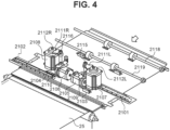
- Fig. 4 is a perspective view of the registration unit 2100 and its surrounding configuration.
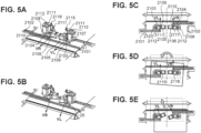
- Figs. 5A to 5E are schematic views of the principal part of the registration unit 2100.
- the registration unit 2100 includes image sensors 2101 and 2102, registration sensors 2103 and 2104, motors 2105 and 2106, steering motors 2107 and 2108, and registration rollers 2109 and 2110.
- a conveyance roller pair 2119 is arranged in the conveyance direction upstream of the sheets S of the registration unit 2100.
- a conveyance roller pair 2118 is arranged in the conveyance direction upstream of the sheets S of the conveyance roller pair 2119.
- the conveyance roller pairs 2118 and 2119 convey the sheets S to the registration unit 2100.
- the conveyance roller pair 2119 functions as a first conveyance unit.
- the configuration of the first conveyance unit is not limited to the configuration of the conveyance roller pair 2119.
- the first conveyance unit can be a belt member that conveys sheets while holding the sheet, for example.
- the registration rollers 2109 and 2110 of the registration unit 2100 receive each of the sheets S conveyed from the conveyance roller pairs 2118 and 2119.
- the registration rollers 2109 and 2110 are rubber rollers made of polyurethane.
- the registration roller 2109 is rotationally driven by the motor 2105.
- the registration roller 2109 forms a nip portion for nipping the sheet S, by pressing a driven roller (not illustrated) facing the registration roller 2109.
- the registration roller 2110 is rotationally driven by the motor 2106.
- the registration roller 2110 forms a nip portion for nipping the sheet S, by pressing a driven roller (not illustrated) facing the registration roller 2110.
- the registration rollers 2109 and 2110 being driven by the motors 2105 and 2106 convey the sheet S toward the print belt unit 2200.
- the registration sensors 2103 and 2104 serve as a first sensor to be used to detect the inclination of the leading edge of the sheet S in the conveyance direction.
- the registration sensors 2103 and 2104 detect timings at which the leading edge (and the trailing end side) of the sheet S passes through the detection positions.
- the detection position of the registration sensor 2103 and the detection position of the registration sensor 2104 differ in a width direction orthogonal to the conveyance direction of the sheet S.
- the registration unit 2100 can correct the skew of the sheets S by adjusting the speed difference between a conveyance speed VL of the registration roller 2109 and a conveyance speed VR of the registration roller 2110.
- the registration unit 2100 also changes the angle of the rotational shaft of the registration roller 2109 with respect to a direction orthogonal to the conveyance direction of the sheets S.
- the rotational shaft of the registration roller 2109 is supported by a steering shaft 2115.
- An axial line direction of the steering shaft 2115 is a direction vertical to the surfaces of the sheets S conveyed by the registration roller 2109.
- the steering shaft 2115 is driven by the steering motor 2107 via a drive input gear 2111L and a motor gear 2112L to rotate around an axial line direction.
- This rotation swings the rotational shaft of the registration roller 2109 around the rotational axis of the steering shaft 2115, whereby the registration roller 2109 controls the skew direction of the sheets S.
- the skew direction refers to a direction (of skew) in which the sheet S is obliquely conveyed with respect to the predetermined conveyance direction.
- the registration unit 2100 changes the angle of the rotational shaft of the registration roller 2110 in a direction orthogonal to the conveyance direction of the sheets S.
- the rotational shaft of the registration roller 2110 is supported by a steering shaft 2116.
- An axial line direction of the steering shaft 2116 is a direction vertical to the surfaces of the sheets S conveyed by the registration roller 2110.
- the steering shaft 2116 is driven by the steering motor 2108 via a drive input gear 2111R and a motor gear 2112R to rotate around an axial line direction. This rotation swings the rotational shaft of the registration roller 2110 around the rotational axis of the steering shaft 2116, whereby the registration roller 2110 controls the skew direction of the sheets S.
- Fig. 5A illustrates a direction in which the registration rollers 2109 and 2110 apply conveyance forces to the sheets S with angles of the rotational shafts of the registration rollers 2109 and 2110 being parallel to an orthogonal direction (width direction) orthogonal to the conveyance direction of the sheets S.
- Rotation of the steering shafts 2115 and 2116 changes the direction in which the registration rollers 2109 and 2110 apply conveyance forces to the sheets S as illustrated in Fig. 5B .
- the image sensor 2101 (or 2102) is a sensor used to detect the position of each of the sheets S in a width direction of the sheet S.
- the image sensor 2101 detects one edge portion of the sheet S, and the image sensor 2102 detects the other edge portion of the sheet S.
- the registration unit 2100 detects the position of the sheet S in the width direction from the detection result of the edge portions of the sheet S, and the angles of the rotational shafts of the registration rollers 2109 and 2110 are adjusted in such a manner that brings the position in the width direction of the sheet S to the target position (width direction).
- the target position (width direction) is assumed to be a center position in the width direction of the print belt 25, for example.
- Fig. 5C is a schematic diagram illustrating a state before a sheet S is conveyed to the registration rollers 2109 and 2110.
- the registration unit 2100 controls the speed difference between the conveyance speeds VL and VR of the registration rollers 2109 and 2110 based on the inclination (skew amount) of the leading edge of a conveyed sheet S detected by the registration sensors 2103 and 2104.
- the orientation of the sheet S is controlled in such a manner that rotates the sheet S to make the leading edge of the sheet S parallel to the width direction.
- Fig. 5C is a schematic diagram illustrating a state before a sheet S is conveyed to the registration rollers 2109 and 2110.
- the registration unit 2100 controls the speed difference between the conveyance speeds VL and VR of the registration rollers 2109 and 2110 based on the inclination (skew amount) of the leading edge of a conveyed sheet S detected by the registration sensors 2103 and 2104.
- the orientation of the sheet S is controlled in such a manner that rotates the sheet
- the registration unit 2100 controls the angles of the rotational shafts of the registration rollers 2109 and 2110 based on the positions of edge portions of the sheet S that are detected by the image sensors 2101 and 2102. With this configuration, even if the conveyance position of the sheet S in the width direction is at a position closer to the registration roller 2110 than the target position (width direction), the sheet S is obliquely conveyed and the print belt 25 holds the sheet S in a state in which the sheet S has reached the target position (width direction).
- the sheet S switched back by the reversing unit 4200 is conveyed by a conveyance roller pair 2400 ( Fig. 1 ) to the conveyance roller pair 2119 ( Fig. 4 ).
- the inkjet recording apparatus switches back the sheet S of which the first surface (front surface) has an image formed on it using the reversing unit 4200, whereby the surfaces of the sheet S with respect to the conveyance direction are reversed.
- the sheet S from the reversing unit 4200 is borne again on the print belt 25 by the conveyance roller pair 2400 ( Fig. 1 ) and the conveyance roller pair 2119 ( Fig. 4 ), and an image is formed by the recording head 10.
- the sheet S is borne on the print belt 25 with the second surface (rear surface) of the sheet S oriented upward, and the image is formed by the recording head 10 on the second surface (rear surface) of the sheet S.
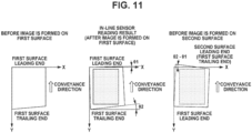
- the leading edge serving as the reference side of the first surface and the leading edge serving as the reference side of the second surface become reversed.
- the leading edge in the conveyance direction of the sheet S before being switched back by the reversing unit 4200 becomes the trailing end side in the conveyance direction of the sheet S through the switch-back performed by the reversing unit 4200.
- the conveyance roller pair 2400 ( Fig. 1 ) function as a third conveyance unit.
- the configuration of the third conveyance unit is not limited to the configuration of the conveyance roller pair 2400.
- the third conveyance unit can be a belt member that conveys a sheet while holding the sheet, for example.
- the orientation of the sheet S is controlled in such a manner that makes the leading edge of the sheet S parallel to the width direction orthogonal to the conveyance direction
- the inclination of the reference side of the first surface and the inclination of the reference side of the second surface are different as illustrated in Fig. 6 .
- the deviation corresponding to ⁇ 2- ⁇ 1 is accordingly generated between the image formed on the first surface of the sheet S and the image formed on the second surface of the sheet S.
- the conveyance position (passing position) of the sheet S in the width direction of the sheet S is controlled in such a manner that makes the center position of the leading edge of the sheet S when an image is formed on the second surface coincide with the center position of the leading edge of the sheet S when an image is formed on the first surface.
- a deviation could be generated in the width direction of the sheet S irrespective of the angle of the leading edge of the sheet S with respect to the conveyance direction.
- the conveyance position in the width direction of the sheet S is wrongly corrected.
- the deviation corresponding to the difference in center position between the leading edge and the trailing end side is generated between the position of an image formed on the first surface and the position of an image formed on the second surface.
- Figs. 8A to 8C illustrate data indicating results of an experiment carried out by the inventors on deviations in the width direction of the sheet S that is attributed to deviations in center position between the leading edge and the trailing end side (deviation in perpendicularity of the sheet S).
- Fig. 8A illustrates a result obtained by measuring deviations in perpendicularities of 500 sheets S one by one.
- the X-axis (horizontal axis) indicates the number of sheets fed, and the Y-axis (vertical axis) indicates amounts of perpendicularity deviation of the sheets S.
- FIG. 8B illustrates a result obtained by measuring deviations (hereinafter, will be referred to as front-rear surface deviations) in image formation position between images on the first surfaces and images on the second surfaces of the 500 sheets S.
- the X-axis (horizontal axis) indicates the number of sheets fed
- the Y-axis (vertical axis) indicates amounts of front-rear surface deviation.
- the amount of perpendicularity deviation of a sheet S is defined as the distance between the corner of the trailing end side of the sheet S and a virtual straight line orthogonal to the leading edge of the sheet S, the virtual straight line being drawn from a corner of the leading edge of the sheet S.
- the trend of the perpendicularity deviation of the sheets S illustrated in Fig. 8A is similar to the trend of the front-rear surface deviation illustrated in Fig. 8B .
- a front-rear surface deviation of an image formed on a sheet S is generated due to a difference in shape between the leading end and the trailing end of the sheet S.
- shape difference device in parallelism or perpendicularity
- variations also occur while images are being formed on a plurality of sheets S.
- the inkjet recording apparatus described in the present embodiment acquires the shape of a sheet S of which the first surface has an image formed on it, and controls the inclination (skew amount) of the leading edge of the sheet S when an image is formed on the second surface of the sheet S, based on the inclinations of the leading edge and the trailing end side of the first surface of the sheet S.
- the inkjet recording apparatus controls the orientation of the sheet S in such a manner that makes the inclination (skew amount) of the leading edge of the sheet S after a switch-back the target inclination for the second surface.
- the inkjet recording apparatus described in the present embodiment determines the target inclination for the leading edge for the second surface using the inclination of the trailing end side of the sheet S of which the first surface has an image formed on it, as well as the inclination (skew amount) of the leading edge of the sheet S of which the first surface has an image formed on it.
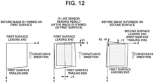
- the inkjet recording apparatus described in the present embodiment also controls the position (reference position) in the width direction of the sheet S at which the sheet S will pass when an image is formed on the second surface of the sheet S, based on the shape of the sheet S of which the first surface has an image formed on it. After the image is formed on the first surface, the center position of the leading edge of the sheet S and the center position of the trailing end side of the sheet S are acquired based on the shape of the sheet S.
- the inkjet recording apparatus shifts the target position for the center position of the leading edge of the second surface of the sheet S in the width direction of the sheet S by an amount corresponding to the difference between the center position of the leading edge of the first surface of the sheet S and the center position of the trailing end side of the first surface of the sheet S.
- margin lengths at the leading end and the trailing end are set to predetermined values. If the leading edge and the trailing end side in the conveyance direction of the sheet S are not parallel, there is, however, a possibility that image formation positions of an image on the first surface and an image on the second surface does not coincide in the conveyance direction.
- the inkjet recording apparatus detects the length in the conveyance direction of the sheet S from the coordinates of the four corners of the sheet S, compares the detected length with a standard length (so-called length) in the conveyance direction that corresponds to its sheet size, and adjusts the margin length at the leading end of an image on the second surface.
- the detected length longer than the reference length results in a long margin length at the trailing end of an image on the first surface, so that the margin length at the leading end of an image on the second surface is made longer than a predetermined value by an amount corresponding to the difference between the detected length and the reference length.
- the detected length shorter than the reference length results in a short margin length at the trailing end of the image on the first surface, so that the margin length at the leading end of an image on the second surface is made shorter than a predetermined value by an amount corresponding to the difference between the detected length and the reference length.
- the inkjet recording apparatus includes the in-line scanner unit 1 provided downstream of the recording head 10 ( Fig. 2 ) in the conveyance direction.
- the in-line scanner unit 1 can read the sheet S immediately after an image is formed on the first surface, at a reading position in the conveyance direction downstream of a recording position at which the recording head 10 ( Fig. 2 ) ejects ink.
- the in-line scanner unit 1 is a second sensor that detects the sheet S while the sheet S is conveyed by the print belt unit 2200.
- the print belt unit 2200 corresponds to a second conveyance unit that conveys the sheet S on which an image is formed.
- the inkjet recording apparatus Based on a read image of the sheet S read by the in-line scanner unit 1, the inkjet recording apparatus acquires the shape, the four corners, and the length of the sheet S in the conveyance direction of the sheet S, and controls the conveyance of the sheet S in forming an image on the second surface.
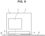
- Fig. 9 is a schematic cross-sectional view of the in-line scanner unit 1 provided in the conveyance direction downstream of the recording head 10 ( Fig. 2 ).
- the in-line scanner unit 1 reads the shape of a sheet S held on the print belt 25 and an image (registration mark) on the sheet S.
- the in-line scanner unit 1 includes a housing 2, a line sensor 3 accommodated in the housing 2, a reading glass 4, and a reference plate 6. By emitting light from a light source (not illustrated) and receiving reflected light from the sheet S via the reading glass 4, the line sensor 3 generates a read image of the sheet S.
- the line sensor 3 is a contact image sensor (CIS) or a charge-coupled device (CCD) sensor.
- the line sensor 3 is movable in such a manner that the line sensor 3 receives reflected light from the reference plate 6.
- the in-line scanner unit 1 performs shading correction for controlling the output value of each pixel from the line sensor 3 to reach a target value, based on the reflected light from the reference plate 6 received by the line sensor 3.
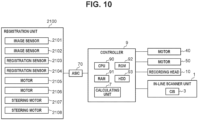
- Fig. 10 is a control block diagram of the inkjet recording apparatus.
- conveyance control of the conveyance of the sheets S under the control of the registration unit 2100 will be described with reference to the control block diagram illustrated in Fig. 10 .
- a controller 9 includes a central processing unit (CPU) 90, and generally controls the inkjet recording apparatus.
- a random access memory (RAM) 91 is a system work memory to be used by the CPU 90 for processing.
- a read-only memory (ROM) 92 stores control programs for controlling various types of processing to be performed in the inkjet recording apparatus.
- a hard disk drive (HDD) 93 stores, in association with each sheet, a read image of the sheet S read by the line sensor 3 of the in-line scanner unit 1, a target inclination for the second surface calculated by a calculating unit 7, a correction value of the target inclination for the second surface, and a margin length of the second surface.
- the calculating unit 7 determines the coordinates of the four corners of the sheet S from the read image on the first surface of the sheet S stored in the HDD 93, and finds the inclinations of the leading edge and the trailing end side of the first surface based on the coordinates.
- the inclination of the leading edge of the first surface is an inclination of the leading edge of a sheet S with respect to a predetermined conveyance direction, the inclination being acquired at the reading position of the in-line scanner unit 1 after an image is formed on the first surface.
- the inclination of the trailing end side of the first surface is an inclination of the trailing end side of a sheet S with respect to a predetermined conveyance direction, the inclination being acquired at the reading position of the in-line scanner unit 1 after an image is formed on the first surface.
- the calculating unit 7 calculates the target inclination for the second surface based on the inclinations of the leading edge and the trailing end side of the first surface.
- the calculating unit 7 functions as a first generation unit that generates the target inclination for the second surface based on data corresponding to the inclination of the leading edge and data corresponding to the inclination of the trailing end side of the sheet S of which the first surface has an image formed on it before the sheet S is switched back.
- the calculating unit 7 determines the coordinates of the center positions of the leading edge and the trailing end side of the first surface based on the coordinate of the four corners of the sheet S, and calculates the correction value for the target inclination for the second surface (width direction) based on the coordinates of the center positions of the leading edge and the trailing end side of the first surface.
- the calculating unit 7 functions as a second generation unit that generates the target position for the second surface (width direction) based on data corresponding to the position at the leading end and data corresponding to the position at the trailing end in the width direction of the sheet S of which the first surface has an image formed on it before the sheet S is switched back. Furthermore, the calculating unit 7 calculates the length in the conveyance direction of the sheet S based on the coordinates of the center positions of the leading edge and the trailing end side of the first surface to determine the margin length at the leading end of the second surface of the sheet S.
- An application specific integrated circuit (ASIC) 70 controls the registration unit 2100.
- the registration unit 2100 (and the ASIC 70) function(s) as an orientation control unit that controls the orientation of the sheet S being conveyed.
- the registration unit 2100 (and the ASIC 70) has (have) a function of controlling the inclination (skew amount) of the leading edge of the sheet S, for example.
- the registration unit 2100 (and the ASIC 70) also has (have) a function of controlling the position in the width direction of a sheet S, for example.
- the following description will be given assuming that the ASIC 70 controls the registration unit 2100, but the CPU 90 of the controller 9 controls the registration unit 2100 in place of the ASIC 70.
- the ASIC 70 To form an image on the first surface of the sheet S, the ASIC 70 detects the end portions in the width direction of the sheet S using the image sensors 2101 and 2102, and detects the inclination (skew amount) of the leading edge in the conveyance direction of the sheet S using the registration sensors 2103 and 2104. Subsequently, the ASIC 70 determines the speed difference between the registration rollers 2109 and 2110 based on the detection results of the registration sensors 2103 and 2104 in such a manner that brings the inclination (skew amount) of the leading edge of the sheet S to a target inclination for the first surface.
- the target inclination for the first surface is a predetermined inclination at which the leading edge of the sheet S is parallel to the width direction of the sheet S.
- the relationship between the speed difference between the two registration rollers 2109 and 2110 for controlling the inclination to bring the inclination to the target inclination, and the inclination (detected inclination) of the leading edge is prestored in the ROM 92 as data.
- the ASIC 70 determines the speed difference (speed difference on the first surface) between the two registration rollers 2109 and 2110 in forming an image on the first surface of the sheet S, based on the inclination (detected inclination) of the leading edge from the data stored in the ROM 92.
- the ASIC 70 then controls the rotational speeds of the motors 2105 and 2106 based on the above-described speed difference on the first surface.
- the ASIC 70 determines the inclinations of the rotational shafts of the registration rollers 2109 and 2110 based on the detection results of the image sensors 2101 and 2102 in such a manner that brings the center position of the leading edge of the sheet S to a target position.
- the target position for the first surface is predetermined and stored in the ROM 92.
- the ASIC 70 controls the amounts of rotation of the steering motors 2107 and 2108 in such a manner that brings the center position to the target position stored in the ROM 92.
- the sheet S is read by the in-line scanner unit 1 provided downstream of the recording head 10 in the conveyance direction.
- the calculating unit 7 determines the target inclination for the leading edge for the second surface before an image is formed on the second surface (rear surface) of the sheet S. A method of determining the target inclination for the second surface will now be described with reference to Fig. 11 .
- the calculating unit 7 After an image is formed on the first surface, the calculating unit 7 detects positions (X1, Y1) to (X4, Y4) of the four corners of the sheet S of which the first surface has the image formed on it, based on a read image of the sheet S read by the in-line scanner unit 1.
- the calculating unit 7 determines the target position in the width direction for the second surface before an image is formed on the second surface of the sheet S. A method of determining the correction value for the target position for the second surface will now be described with reference to Fig. 12 .
- the sheet S read by the in-line scanner unit 1 is conveyed to the reversing unit 4200.
- a roller (not illustrated) of the reversing unit 4200 rotates reversely, switching-back the sheet S.
- the sheet S switched back in the reversing unit 4200 is conveyed again to the registration unit 2100 via a plurality of conveyance rollers including the conveyance roller pairs 2118, 2119, and 2400 with the second surface oriented upward.
- the ASIC 70 To form an image on the second surface of the sheet S, the ASIC 70 detects the end portions in the width direction of the sheet S using the image sensors 2101 and 2102, and detects the inclination (skew amount) of the leading edge in the conveyance direction of the sheet S using the registration sensors 2103 and 2104. The ASIC 70 then determines the speed difference between the registration rollers 2109 and 2110 based on the detection results of the registration sensors 2103 and 2104 in such a manner that brings the inclination (skew amount) of the leading edge of the sheet S to the target inclination (target skew amount) of the leading edge for the second surface.
- the speed difference for controlling the inclination (skew amount) of the leading edge of the second surface is also determined with reference to the data stored in the ROM 92.
- the ASIC 70 determines the speed difference (speed difference on the second surface) between the two registration rollers 2109 and 2110 in forming an image on the second surface of the sheet S, based on the inclination (detected inclination) of the leading edge from the data stored in the ROM 92.
- the ASIC 70 then controls the rotational speeds of the motors 2105 and 2106 based on the above-described speed difference between the two registration rollers 2109 and 2110 on the second surface.
- the ASIC 70 determines the inclinations of the rotational shafts of the registration rollers 2109 and 2110 based on the detection results of the image sensors 2101 and 2102 in such a manner that beings the center position of the leading edge of the sheet S to a target position for the second surface.
- the ASIC 70 determines the target position for the second surface by adding the correction value ⁇ X to the target position for the first surface.
- the ASIC 70 controls the amounts of rotation of the steering motors 2107 and 2108 in such a manner that brings the center position to the target position for the second surface.
- control of the conveyance of a sheet S by the registration unit 2100 allows accurate reduction of the front-rear surface deviation between an image on the first surface of the sheet S and an image on the second surface of the sheet S.
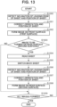
- FIG. 13 An image forming operation in which the inkjet recording apparatus functioning as an image forming apparatus forms an image on a sheet will now be described with reference to a flowchart illustrated in Fig. 13 .
- This image forming operation is performed by the CPU 90 of the controller 9 loading a control program stored in the ROM 92 onto the RAM 91.
- the image forming operation illustrated in the flowchart in Fig. 13 is performed by an image formation job (image data) being transferred from an external device (server or personal computer).
- step S 1000 the CPU 90 first feeds a sheet S using the sheet feeding module 1000, and causes the registration unit 2100 to detect the inclination and the position of the leading edge of the sheet S.
- step S1001 the CPU 90 corrects the orientation (inclination) and the position of the sheet S.
- step S1002 the CPU 90 causes the recording unit 2300 to form an image on the first surface of the sheet S.
- step S 1003 the CPU 90 determines whether an image is to be formed on the rear surface (second surface) of the sheet S, based on information indicated by image data.
- step S1003 If an image is to be formed on the rear surface (second surface) of the sheet S (YES in step S1003), the processing proceeds to step S1004.
- step S1004 the CPU 90 subsequently causes the in-line scanner unit 1 to read the sheet S, and acquires an angle difference ⁇ 2- ⁇ 1 calculated by the calculating unit 7, and a correction value ⁇ X.
- the sheet S is conveyed through the drying module 3000 and the fixing module 4000 to the cooling module 5000.
- the CPU 90 causes the conveyance path switching unit of the cooling module 5000 to convey the sheet S to the reversing module 6000.
- the CPU 90 conveys the sheet S to the reversing unit 4200 and switches back the sheet S.
- the sheet S switched back in the reversing unit 4200 is conveyed via the conveyance roller pair 2400 and the sheet feeding module 1000 to the print module 2000.
- step S1003 if it is determined that an image is not to be formed on the rear surface of the sheet S (NO in step S1003), the processing proceeds to step S1009.
- step S1009 the CPU 90 determines whether all images included in the image data are formed. In step S1009, if it is determined in step S1009 that all images are formed (YES in step S1009), the CPU 90 ends the processing. If it is determined that all images are not formed (NO in step S1009), the CPU 90 returns the processing to step S1000, and starts image formation on the next sheet.
- the sheet S on which an image is formed is conveyed through the reversing module 6000 to the sheet discharging and stacking module 7000.
- step S1006 the CPU 90 causes the registration unit 2100 to detect the inclination and the position of the leading edge of the sheet S.
- step S 1007 the CPU 90 corrects the orientation (inclination) and the position of the sheet S.
- step S 1007 the CPU 90 causes the registration unit 2100 to correct the orientation (inclination) of the sheet S based on the angle difference acquired in step S 1006 and the inclination of the leading edge acquired in step S1004.
- step S1007 the CPU 90 also causes the registration unit 2100 to correct the position of the sheet S based on the position of the sheet S acquired in step S1006 and the correction value ⁇ X acquired in step S1004.
- step S1008 the CPU 90 causes the recording unit 2300 to form an image on the second surface of the sheet S.
- step S 1009 the CPU 90 determines whether all images included in the image data are formed. When it is determined in step S 1009 that all images are not formed (NO in step S1009), the CPU 90 returns the processing to step S 1000, and starts image formation on the next sheet.
- the sheet S on which an image is formed is conveyed through the reversing module 6000 to the sheet discharging and stacking module 7000.
- the above-described image forming operation allows reduction of the deviation in formation position between an image on the front surface (first surface) of the sheet S and an image on the rear surface (second surface) of the sheet S.
- the calculating unit 7 generates both the target inclination and the target position for the second surface using a read image of the sheet S read by the in-line scanner unit 1.
- the calculating unit 7 can generate the target inclination for the second surface using a read image of the sheet S read by the in-line scanner unit 1 without making the target position for the second surface variable.
- This configuration also allows reduction of a front-rear surface deviation attributed to a parallelism deviation, providing a reduced deviation in image formation position compared with a configuration in which the target inclination for the second surface is not made variable.
- the calculating unit 7 can generate the target position for the second surface using a read image of the sheet S read by the in-line scanner unit 1, without making the target inclination for the second surface variable.
- This configuration allows reduction of a front-rear surface deviation attributed to a perpendicularity deviation, providing a reduced deviation in image formation position compared with a configuration in which the target position for the second surface is not made variable.
- the image forming apparatus can be an electrophotographic printer including a photosensitive member, a charging device that charges the photosensitive member, an exposure device that exposes the photosensitive member to form an electrostatic latent image on the photosensitive member, and a developing device that develops the electrostatic latent image on the photosensitive member using toner.
- the charging device, the exposure device, and the developing device are called an image forming station.
- the image forming station forms an image by transferring an image to the sheet S conveyed to a transfer nip in the direction in which the sheet S is conveyed.
- the electrophotographic printer further includes a fixing device that fixes the image to the sheet S downstream of the transfer nip in the conveyance direction in which the sheet S is conveyed, and a reversing unit that switches back the sheet S further downstream of the fixing device in the conveyance direction.
- the electrophotographic printer can be used as long as the electrophotographic printer has a configuration including the registration unit 2100 in the conveyance direction of the sheet S upstream of the transfer nip at which an image is transferred to the sheet S, and including the in-line scanner unit 1 in the conveyance direction of the sheet S downstream of the transfer nip.
- the in-line scanner unit 1 can be arranged in the printer so as to read the sheet S at a position between the transfer nip and the fixing device in the conveyance direction.
- the in-line scanner unit 1 can be arranged so as to read the sheet S at a position between the fixing device and the reversing unit in the conveyance direction.
- the fixing device functions as a fixing unit as with the fixing module 4000 (fixing belt unit 4100).
Landscapes
- Physics & Mathematics (AREA)
- General Physics & Mathematics (AREA)
- Engineering & Computer Science (AREA)
- Mechanical Engineering (AREA)
- Microelectronics & Electronic Packaging (AREA)
- Registering Or Overturning Sheets (AREA)
- Ink Jet (AREA)
- Handling Of Sheets (AREA)
- Paper Feeding For Electrophotography (AREA)
Applications Claiming Priority (1)
| Application Number | Priority Date | Filing Date | Title |
|---|---|---|---|
| JP2023088267A JP2024171277A (ja) | 2023-05-29 | 2023-05-29 | 画像形成装置 |
Publications (3)
| Publication Number | Publication Date |
|---|---|
| EP4471504A1 true EP4471504A1 (de) | 2024-12-04 |
| EP4471504B1 EP4471504B1 (de) | 2025-12-24 |
| EP4471504C0 EP4471504C0 (de) | 2025-12-24 |
Family
ID=91331071
Family Applications (1)
| Application Number | Title | Priority Date | Filing Date |
|---|---|---|---|
| EP24178612.8A Active EP4471504B1 (de) | 2023-05-29 | 2024-05-28 | Bilderzeugungsgerät |
Country Status (5)
| Country | Link |
|---|---|
| US (1) | US20240402636A1 (de) |
| EP (1) | EP4471504B1 (de) |
| JP (1) | JP2024171277A (de) |
| KR (1) | KR20240171008A (de) |
| CN (1) | CN119045294A (de) |
Families Citing this family (1)
| Publication number | Priority date | Publication date | Assignee | Title |
|---|---|---|---|---|
| EP4169724B1 (de) * | 2021-10-21 | 2025-09-17 | Canon Production Printing Holding B.V. | Blattregistrierungsvorrichtung für nicht rechteckige blätter |
Citations (2)
| Publication number | Priority date | Publication date | Assignee | Title |
|---|---|---|---|---|
| US20090134569A1 (en) | 2007-11-27 | 2009-05-28 | Canon Kabushiki Kaisha | Sheet conveying apparatus and image forming apparatus |
| US20120301198A1 (en) * | 2011-05-25 | 2012-11-29 | Fuji Xerox Co., Ltd. | Image forming system, image forming method, and non-transitory computer readable medium |
Family Cites Families (1)
| Publication number | Priority date | Publication date | Assignee | Title |
|---|---|---|---|---|
| JP5928494B2 (ja) * | 2014-01-22 | 2016-06-01 | コニカミノルタ株式会社 | 画像形成装置 |
-
2023
- 2023-05-29 JP JP2023088267A patent/JP2024171277A/ja active Pending
-
2024
- 2024-05-21 KR KR1020240065621A patent/KR20240171008A/ko active Pending
- 2024-05-24 US US18/674,494 patent/US20240402636A1/en active Pending
- 2024-05-27 CN CN202410661119.7A patent/CN119045294A/zh active Pending
- 2024-05-28 EP EP24178612.8A patent/EP4471504B1/de active Active
Patent Citations (2)
| Publication number | Priority date | Publication date | Assignee | Title |
|---|---|---|---|---|
| US20090134569A1 (en) | 2007-11-27 | 2009-05-28 | Canon Kabushiki Kaisha | Sheet conveying apparatus and image forming apparatus |
| US20120301198A1 (en) * | 2011-05-25 | 2012-11-29 | Fuji Xerox Co., Ltd. | Image forming system, image forming method, and non-transitory computer readable medium |
Also Published As
| Publication number | Publication date |
|---|---|
| CN119045294A (zh) | 2024-11-29 |
| JP2024171277A (ja) | 2024-12-11 |
| EP4471504B1 (de) | 2025-12-24 |
| KR20240171008A (ko) | 2024-12-06 |
| US20240402636A1 (en) | 2024-12-05 |
| EP4471504C0 (de) | 2025-12-24 |
Similar Documents
| Publication | Publication Date | Title |
|---|---|---|
| US9316986B2 (en) | Recording medium discharging device | |
| US8757757B2 (en) | Printing apparatus | |
| US12091278B2 (en) | Printing apparatus and control method thereof | |
| US8376543B2 (en) | Recording apparatus and sheet processing method | |
| US9358812B2 (en) | Printing apparatus for detecting and avoiding unprintable regions on recording mediums | |
| US8734037B2 (en) | Printing apparatus | |
| US10875730B2 (en) | Sheet conveying device, image forming apparatus incorporating the sheet conveying device, and sheet conveying method using the sheet conveying device | |
| US11479433B2 (en) | Sheet conveying device and image forming apparatus incorporating the sheet conveying device | |
| EP4471504B1 (de) | Bilderzeugungsgerät | |
| US7441772B2 (en) | Sheet-conveying device | |
| US9108820B2 (en) | Sheet folding apparatus and image forming apparatus | |
| US9769327B2 (en) | Image forming apparatus and method of positional adjustment in image formation | |
| US7532854B2 (en) | Image forming apparatus including discharging roller decelerating unit and method of decelerating discharging roller | |
| EP3459750B1 (de) | Druckvorrichtung und druckverfahren | |
| US11546478B2 (en) | Correcting back side image data based on positions of four corner detection marks specified using ground color luminance | |
| US10960687B2 (en) | Image forming apparatus | |
| US20250381786A1 (en) | Sheet conveyance apparatus and image forming apparatus | |
| US20240408906A1 (en) | Technology for controlling shape of image formed by image forming apparatus | |
| US12129146B2 (en) | Sheet path intersection device | |
| US20250346053A1 (en) | Image forming apparatus and adjustment method for the image forming apparatus | |
| US20260093198A1 (en) | Image forming system and image reading apparatus | |
| JP2025080594A (ja) | 画像形成装置 | |
| JP2001335194A (ja) | 画像形成装置および複写機 | |
| JP2008030883A (ja) | 用紙搬送装置および用紙姿勢補正方法 | |
| JP2001031311A (ja) | シートカール検知装置およびシートカール修正装置 |
Legal Events
| Date | Code | Title | Description |
|---|---|---|---|
| PUAI | Public reference made under article 153(3) epc to a published international application that has entered the european phase |
Free format text: ORIGINAL CODE: 0009012 |
|
| STAA | Information on the status of an ep patent application or granted ep patent |
Free format text: STATUS: THE APPLICATION HAS BEEN PUBLISHED |
|
| AK | Designated contracting states |
Kind code of ref document: A1 Designated state(s): AL AT BE BG CH CY CZ DE DK EE ES FI FR GB GR HR HU IE IS IT LI LT LU LV MC ME MK MT NL NO PL PT RO RS SE SI SK SM TR |
|
| STAA | Information on the status of an ep patent application or granted ep patent |
Free format text: STATUS: REQUEST FOR EXAMINATION WAS MADE |
|
| 17P | Request for examination filed |
Effective date: 20250604 |
|
| GRAP | Despatch of communication of intention to grant a patent |
Free format text: ORIGINAL CODE: EPIDOSNIGR1 |
|
| STAA | Information on the status of an ep patent application or granted ep patent |
Free format text: STATUS: GRANT OF PATENT IS INTENDED |
|
| INTG | Intention to grant announced |
Effective date: 20250716 |
|
| GRAS | Grant fee paid |
Free format text: ORIGINAL CODE: EPIDOSNIGR3 |
|
| GRAA | (expected) grant |
Free format text: ORIGINAL CODE: 0009210 |
|
| STAA | Information on the status of an ep patent application or granted ep patent |
Free format text: STATUS: THE PATENT HAS BEEN GRANTED |
|
| AK | Designated contracting states |
Kind code of ref document: B1 Designated state(s): AL AT BE BG CH CY CZ DE DK EE ES FI FR GB GR HR HU IE IS IT LI LT LU LV MC ME MK MT NL NO PL PT RO RS SE SI SK SM TR |
|
| REG | Reference to a national code |
Ref country code: CH Ref legal event code: F10 Free format text: ST27 STATUS EVENT CODE: U-0-0-F10-F00 (AS PROVIDED BY THE NATIONAL OFFICE) Effective date: 20251224 Ref country code: GB Ref legal event code: FG4D |
|
| REG | Reference to a national code |
Ref country code: DE Ref legal event code: R096 Ref document number: 602024001801 Country of ref document: DE |
|
| U01 | Request for unitary effect filed |
Effective date: 20251231 |
|
| U07 | Unitary effect registered |
Designated state(s): AT BE BG DE DK EE FI FR IT LT LU LV MT NL PT RO SE SI Effective date: 20260109 |