EP4471233A1 - Outil d'application pour plafond - Google Patents
Outil d'application pour plafond Download PDFInfo
- Publication number
- EP4471233A1 EP4471233A1 EP23177092.6A EP23177092A EP4471233A1 EP 4471233 A1 EP4471233 A1 EP 4471233A1 EP 23177092 A EP23177092 A EP 23177092A EP 4471233 A1 EP4471233 A1 EP 4471233A1
- Authority
- EP
- European Patent Office
- Prior art keywords
- application
- support
- handle
- head
- tool
- Prior art date
- Legal status (The legal status is an assumption and is not a legal conclusion. Google has not performed a legal analysis and makes no representation as to the accuracy of the status listed.)
- Withdrawn
Links
Images




Classifications
-
- E—FIXED CONSTRUCTIONS
- E04—BUILDING
- E04F—FINISHING WORK ON BUILDINGS, e.g. STAIRS, FLOORS
- E04F21/00—Implements for finishing work on buildings
- E04F21/02—Implements for finishing work on buildings for applying plasticised masses to surfaces, e.g. plastering walls
- E04F21/06—Implements for applying plaster, insulating material, or the like
Definitions
- the invention relates to an application tool for ceiling or wall or floor.
- the invention relates to a tool for applying, spreading and smoothing a coating or paint for a ceiling.
- a tool comprising a handle at the end of which an application element is arranged.
- This tool is held by the operator via the handle with both hands.
- the operator performs a movement, for example back and forth, with the tool on the surface of the ceiling in order to coat or paint it.
- the handle can be adjustable according to the size of the operator.
- the disadvantage of this tool is that it requires the operator to have his arms high as visible at the figure 1 to carry said tool while moving them to spread the coating or paint. Such a position is uncomfortable and can eventually lead to musculoskeletal disorders. Indeed, when using said tool, the entire weight of the tool rests on the operator's arms. In addition, the operator must constantly look at the ceiling to be sure of having contact between the tool and the ceiling and for guidance.
- the present invention aims to provide a tool that solves the problems of the prior art by providing a more comfortable coating/paint application tool.
- the invention relates to an assembly for applying material to a surface comprising an application tool, said application tool comprising a handle at one end of which an application head is arranged, characterized in that said application assembly comprises a support capable of being carried by an operator, in that the handle comprises at its other end a support head, said support comprising a receiving surface arranged to cooperate with the support head.
- the present invention allows the weight of the tool to be diverted from the user's arms to the support carried by the operator. This relieves the operator's arms.
- the presence of the application head and support allows easy engagement/disengagement.
- the support head is at least partially spherical, said receiving surface being concave.
- the support head is triangular or parallelepipedal, said receiving surface being the inverse of the support head.
- the support head is pivotally mounted relative to the handle.
- the application head is attached to the handle.
- the application head is pivotally mounted relative to the handle.
- the handle is adjustable in length.
- the bracket is mounted on a belt or harness.
- the invention shown in the figure 2 shows an application tool 10 according to the invention.
- the application tool 10 comprises a handle 11 in the form of a rod or a tube.
- an application element 12 is arranged on a first end of the handle.
- This application element 12 is an element allowing a coating or paint or the like to be applied, spread on a surface.
- the application element 12 is in the form of a roller or a trowel or a scraper.
- the application tool makes it possible to apply, spread, smooth a coating or an adhesive or a paint or a seal or any other spreadable material.
- the handle 11 is arranged to be adjustable to adapt to the morphology, more precisely the size, of the operator as visible at the figure 3 .
- the handle 11 comprises two portions sliding one inside the other and associated with a locking means for locking the portion of the two portions 11a, 11b relative to each other.
- the tool 10 is associated with a support 20 to form an application assembly 1.
- This application assembly 1 is in the form of a kit.
- the support 20 comprises a receiving surface 22 as visible in the figure 4 .
- This receiving surface 22 is arranged to cooperate with the second end of the handle.
- the second end of the handle 11 comprises a support head 14.
- This support head 14 has a shape such that it cooperates with the receiving surface 22 of the support 20. This cooperation allows the handle 11 to rest on the support. The handle 11 thus supported by the support 20, the operator does not need to raise his arms to bring the support and the application head to the ceiling as visible in the figure 10 .
- the support head 14 is of circular, spherical shape.
- the receiving surface is also of substantially circular, spherical shape.
- the support head 14 has a partially spherical shape and the receiving surface 22 has a concave shape, preferably inverse to this partial sphere.
- This first embodiment allows the partially spherical shape of the support head to cooperate perfectly with the inverse shape of the receiving surface.
- the movement zone of the handle is a cone, it is then understood that the support head is the apex of this cone-shaped movement zone.
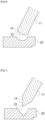
- the support head 14 is preferably semi-spherical, and even more preferably spherical as visible in the figure 6 .
- the receiving surface 22 is partially spherical, half-spherical or in the form of a cylinder provided with a partially spherical bottom.
- the receiving surface is thus in the form of a housing.
- the support head 14 is wedged in the receiving surface 22, thus preventing said support head from coming out.
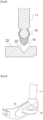
- the support head 14 has a triangular or parallelepiped shape.
- the support head is then, optionally, connected to the handle by a ball joint system 14' as visible in the figure 8 .
- the support head 14 is able to be inserted into the receiving surface 22 which is in the form of a housing, the shape of which allows the support head to be fitted into said housing.
- the combination of the triangular or parallelepiped shape with the 14' ball joint system prevents the support head from coming out of its housing while ensuring good handling of the tool.
- This second embodiment makes it possible to have the support head 14 which is held in the housing while allowing the handle 11 to move in a cone thanks to the ball joint.
- the support 20 is arranged to be carried by the operator as visible to the figure 9 .
- the support is then associated with a fastening element 30.
- This fastening element 30 is in the form of a belt or a harness.
- Such a belt or harness is attached to the operator.
- the operator equips himself with the harness 30 or the belt 30 and attaches it. He then equips himself with the application tool. He adjusts the length of the handle, if possible, and makes the support head cooperate with the receiving surface as visible in the figure 10 .
- This cooperation between the support head 14 and the receiving surface 22 makes it possible to block the application tool 10 with the receiving surface as visible in the figure 11 . Since the receiving surface of the support is part of the attachment element (belt or harness), the application tool 10 is therefore carried by the operator's body, not his arms. The operator's arms are then used to move the application tool and apply the coating or paint.
- the handle 11 of the application tool 10 is arranged so that the application head 12 is angularly adjustable.
- This angular adjustment makes it possible to have an angle between the axis of the handle and the application head to improve the handling of the application head. For this, several solutions are possible.
- the first solution the simplest, consists of having an application head that is interchangeable. We then understand that the application head is an added part as visible at the figure 12 . This application head 12 is then fixed to the handle 11 by screwing or snapping or by bayonet fixing. In this solution, the application head is then associated with a fixing portion which consists of a tubular portion fixing to the handle.
- This solution allows you to mount an application head that has a curved fixing portion or that has an angle relative to the axis of the handle.
- a second solution is to have a pivotally mounted application head 12 as seen in the figure 13 .
- a first assembly consists of having a pivoting interface between the handle 11 and the application head 12.
- This pivoting interface comprises a ball joint or a universal joint or a fork carrying an axle.
- This pivoting interface allows the application head to be pivotable through at least 180 degrees. This pivoting interface thus allows the application head to remain pressed against the surface to be coated during application by the operator and his movements of the tool.
- first solution and the second solution are not incompatible. Indeed, it is possible to have an application head mounted pivoting on a ball or cardan but which is also an added part.
- the invention described can be used for the application of coating or paint on a ceiling, it can also be used for application on walls, particularly for very high walls.
- the invention can also be used for coating floors.
- the receiving surface is positioned on the support accordingly as visible on the figure 14 . More specifically, the receiving surface is oriented in a direction parallel to the ground, unlike the position of the receiving surface which, for an action of coating a ceiling, will be oriented in a direction perpendicular to the ground plane.
Landscapes
- Engineering & Computer Science (AREA)
- Architecture (AREA)
- Civil Engineering (AREA)
- Structural Engineering (AREA)
- Coating Apparatus (AREA)
Abstract
1. La présente invention concerne un ensemble d'application de matière sur une surface comprenant un outil d'application (10), ledit outil d'application comprenant un manche (11) à une extrémité duquel une tête d'application (12) est agencée, caractérisé en ce que ledit ensemble d'application comprend un support (20) apte à être porté par un opérateur, en ce que le manche comprend à son autre extrémité une tête d'appui (14), ledit support comprenant une surface de réception (22) agencée pour coopérer avec la tête d'appui.
Description
- L'invention concerne un outil d'application pour plafond ou mur ou sol.
- L'invention concerne un outil d'application, d'étalement, de lissage d'un enduit ou peinture pour plafond.
- Actuellement, l'application d'une peinture ou d'un enduit sur un plafond se fait à l'aide d'un outil comprenant un manche à l'extrémité duquel un élément d'application est agencé. Cet outil est tenu par l'opérateur via le manche à deux mains. L'opérateur effectue un mouvement, par exemple de va et vient, avec l'outil sur la surface du plafond afin de l'enduire ou de la peindre. Le manche peut être réglable en fonction de la taille de l'opérateur.
- Néanmoins, l'inconvénient de cet outil est qu'il nécessite pour l'opérateur d'avoir les bras en hauteur comme visible à la
figure 1 pour porter ledit outil tout en les bougeant pour étaler l'enduit ou la peinture. Une telle position est inconfortable et peut entrainer, à terme, des troubles musculosquelettiques. En effet, lors de l'utilisation dudit outil, la totalité du poids de l'outil repose sur les bras de l'opérateur. Par ailleurs, l'opérateur doit regarder le plafond en permanence pour être sûre d'avoir le contact entre l'outil et le plafond et pour le guidage. - La présente invention a pour but de fournir un outil qui résout les problèmes de l'art antérieur en proposant un outil d'application d'un enduit /d'une peinture qui soit plus confortable.
- A cette effet, l'invention concerne un ensemble d'application de matière sur une surface comprenant un outil d'application, ledit outil d'application comprenant un manche à une extrémité duquel une tête d'application est agencée, caractérisé en ce que ledit ensemble d'application comprend un support apte à être porté par un opérateur, en ce que le manche comprend à son autre extrémité une tête d'appui , ledit support comprenant une surface de réception agencé pour coopérer avec la tête d'appui.
- La présente invention permet dévier le poids de l'outil des bras de l'utilisateur vers le support porté par l'opérateur. Cela permet de soulager les bras de l'opérateur.
- De plus, la présence de la tête d'application et du support permet un engagement / désengagement facile.
- Selon un exemple, la tête d'appui est au moins partiellement sphérique, ladite surface de réception étant concave.
- Selon un exemple, la tête d'appui est triangulaire ou parallélépipédique, ladite surface de réception étant l'inverse de la tête d'appui.
- Selon un exemple, la tête d'appui est montée pivotante par rapport au manche.
- Selon un exemple, la tête d'application est rapportée au manche.
- Selon un exemple, la tête d'application est montée pivotante par rapport au manche.
- Selon un exemple, le manche est réglable en longueur.
- Selon un exemple, le support est monté sur une ceinture ou un harnais.
- L'invention concerne en outre une méthode d'application d'un enduit ou d'une peinture sur une surface, ladite méthode utilisant l'ensemble d'application selon l'une des revendications précédentes, dans laquelle la méthode comprend les étapes suivantes :
- Se munir du support et de l'outil d'application ;
- Mettre en place le support ;
- Faire coopérer la tête d'appui du manche avec la surface de réception du support ;
- Manipuler le manche pour appliquer ledit enduit ou ladite peinture.
- D'autres particularités et avantages ressortiront clairement de la description qui en est faite ci-après, à titre indicatif et nullement limitatif, en référence aux dessins annexés, dans lesquels :
- la
figure 1 représente une vue d'un opérateur qui porte un outil d'application selon l'art antérieur; - la
figure 2 représente une vue d'un outil d'application selon l'invention; - la
figure 3 représente une variante réglable en longueur d'un outil d'application selon l'invention; - la
figure 4 représente une vue d'un support avec surface de réception ; - les
figures 5 et6 représentent des vues d'une tête d'appui sphérique ou partiellement sphérique d'un outil d'application de l'invention; - les
figures 5 et6 représentent des vues d'une tête d'appui non sphérique d'un outil d'application de l'invention; - les
figures 9 à 11 représentent des vues d'un ensemble d'application selon l'invention; - les
figures 12 et13 représentent des vues d'une variante d'un outil d'application selon l'invention; - la
figure 14 représente une vue d'un support avec surface de réception orienté pour une application sur le sol; - L'invention représentée sur la
figure 2 montre un outil d'application 10 selon l'invention. L'outil d'application 10 comprend un manche 11 sous forme d'une tige ou d'un tube. Sur une première extrémité du manche, un élément d'application 12 est agencé. Cet élément d'application 12 est un élément permettant à un enduit ou une peinture ou autre d'être appliqué, étalé sur une surface. Par exemple, l'élément d'application 12 se présente sous la forme d'un rouleau ou d'une taloche ou d'un racloir. L'outil d'application permet d'appliquer, d'étaler, de lisser un enduit ou une colle ou une peinture ou un joint ou tout autre matériau étalable. - Le manche 11 est agencé pour être réglable pour s'adapter à la morphologie, plus précisément la taille, de l'opérateur comme visible à la
figure 3 . Pour cela, le manche 11 comprend deux portions coulissantes l'une dans l'autre et associées à un moyen de verrouillage pour verrouiller la portion des deux portions 11a, 11b l'une par rapport à l'autre. - Selon l'invention, l'outil 10 est associé à un support 20 pour former un ensemble d'application 1. Cet ensemble d'application 1 se présente sous la forme d'un kit.
- Le support 20 comprend une surface de réception 22 comme visible à la
figure 4 . Cette surface de réception 22 est agencée pour coopérer avec la seconde extrémité du manche. En effet, la seconde extrémité du manche 11 comprend une tête d'appui 14. Cette tête d'appui 14 présente une forme telle qu'elle coopère avec la surface de réception 22 du support 20. Cette coopération permet au manche 11 de prendre appui sur le support. Le manche 11 ainsi supporté par le support 20, l'opérateur n'a pas besoin de lever ses bras pour amener le support et la tête d'application au plafond comme visible à lafigure 10 . - Dans un premier mode de réalisation visible à la
figure 5 , la tête d'appui 14 est de forme circulaire, sphérique. La surface de réception est également de forme sensiblement circulaire, sphérique. - La tête d'appui 14 présente une forme partiellement sphérique et la surface de réception 22 présente une forme concave, de préférence inverse à cette sphère partielle. Cette première exécution permet à la forme partiellement sphérique de la tête d'appui de coopérer parfaitement avec la forme inverse de la surface de réception. Ainsi, une fois le manche 11 en appui sur le support, cela permet à l'opérateur de déplacer le manche. La zone de déplacement du manche est un cône, on comprend alors que la tête d'appui est le sommet de cette zone de déplacement en forme de cône.
- La tête d'appui 14 est, de préférence, demi-sphérique, et encore plus de préférence sphérique comme visible à la
figure 6 . Dans ce cas, la surface de réception 22 est partiellement sphérique, demi sphérique ou sous la forme d'un cylindre muni d'un fond partiellement sphérique. La surface de réception se présente ainsi sous la forme d'un logement. Dans ce cas, la tête d'appui 14 est coincée dans la surface de réception 22, empêchant ainsi ladite tête d'appui de sortir. - Dans un second mode réalisation visible à la
figure 7 , la tête d'appui 14 présente une forme triangulaire ou parallélépipédique. La tête d'appui est alors, optionnellement, reliée au manche par un système de rotule 14' comme visible à lafigure 8 . La tête d'appui 14 est apte à s'insérer dans la surface de réception 22 qui se présente sous la forme d'un logement donc la forme permet l'emboitement de la tête d'appui dans ledit logement. L'association de la forme triangulaire ou parallélépipédique avec le système de rotule 14' permet d'éviter que la tête d'appui ne sorte de son logement tout en assurant une bonne maniabilité de l'outil. - Ce second mode de réalisation permet d'avoir la tête d'appui 14 qui est maintenue dans le logement tout en permettant au manche 11 de se déplacer dans un cône grâce à la rotule.
- Selon l'invention, le support 20 est agencé pour être porté par l'opérateur comme visible à la
figure 9 . Le support est alors associé à un élément d'attache 30. Cet élément d'attache 30 se présente sous la forme d'une ceinture ou d'un harnais. Une telle ceinture ou harnais se fixe sur l'opérateur. En fonctionnement, l'opérateur se munit du harnais 30 ou de la ceinture 30 et l'attache. Il se munit ensuite de l'outil d'application. Il règle la longueur du manche, si possible, et fait coopérer la tête d'appui avec la surface de réception comme visible à lafigure 10 . Cette coopération entre la tête d'appui 14 et la surface de réception 22 permet de bloquer l'outil d'application 10 avec la surface de réception comme visible à lafigure 11 . Comme la surface de réception du support fait partie de l'élément d'attache (ceinture ou harnais), l'outil d'application 10 est donc porté par le corps de l'opérateur, non ses bras. Les bras de l'opérateur sont alors utilisés pour déplacer l'outil d'application et appliquer l'enduit ou la peinture. - Dans une variante, le manche 11 de l'outil d'application 10 est agencé pour que la tête d'application 12 soit angulairement réglable. Ce réglage angulaire permet d'avoir un angle entre l'axe du manche et la tête d'application pour améliorer la manipulation de la tête d'application. Pour cela, plusieurs solutions sont envisageables.
- La première solution, la plus simple, consiste à avoir une tête d'application qui est interchangeable. On comprend alors que la tête d'application est une pièce rapportée comme visible à la
figure 12 . Cette tête d'application 12 est alors fixée au manche 11 par vissage ou encliquetage ou par fixation à baïonnette. Dans cette solution, la tête d'application est alors associée à une portion de fixation qui consiste en une portion tubulaire se fixant au manche. - Cette solution permet de monter une tête d'application qui présente une portion de fixation courbe ou qui présente un angle par rapport à l'axe du manche.
- Une seconde solution consiste à avoir une tête d'application 12 montée pivotante comme visible à la
figure 13 . Pour cela, un premier montage consiste à avoir une interface pivotante entre le manche 11 et la tête d'application 12. Cette interface pivotante comprend une rotule ou un cardan ou une fourche portant un axe. Cette interface pivotante permet à la tête d'application d'être pivotante sur au moins 180 degrés. Cette interface pivotante permet ainsi à la tête d'application de rester plaquée sur la surface à enduire lors de l'application par l'opérateur et ses mouvements de l'outil. - Bien entendu, la première solution et la seconde solution ne sont pas incompatibles. En effet, il est possible d'avoir une tête d'application montée pivotante sur roture ou cardan mais qui est également une pièce rapportée.
- Bien entendu, la présente invention ne se limite pas à l'exemple illustré mais est susceptible de diverses variantes et modifications qui apparaîtront à l'homme de l'art.
- En effet, si l'invention décrite est utilisable pour l'application d'enduit ou peinture sur un plafond, elle est aussi utilisable pour l'application sur des murs notamment pour des murs de grande hauteur.
- L'invention est également utilisable pour enduire des sols. Dans ce cas, la surface réceptrice est positionnée sur le support en conséquence comme visible à la
figure 14 . Plus particulièrement, la surface de réception est orientée dans une direction parallèle au sol contrairement à la position de la surface de réception qui, pour une action d'enduire un plafond, va être orientée dans une direction perpendiculaire au plan du sol.
Claims (9)
- Ensemble d'application (1) de matière sur une surface comprenant un outil d'application (10), ledit outil d'application comprenant un manche (11) à une extrémité duquel une tête d'application (12) est agencée, caractérisé en ce que ledit ensemble d'application comprend un support (20) apte à être porté par un opérateur, en ce que le manche comprend à son autre extrémité une tête d'appui (14), ledit support comprenant une surface de réception (22) agencée pour coopérer avec la tête d'appui.
- Ensemble selon la revendication précédente, dans lequel la tête d'appui (14) est au moins partiellement sphérique, ladite surface de réception étant concave.
- Ensemble selon la revendication précédente, dans lequel la tête d'appui (14) est triangulaire ou parallélépipédique, ladite surface de réception étant l'inverse de la tête d'appui.
- Ensemble d'application selon la revendication précédente, dans lequel la tête d'appui est montée pivotante par rapport au manche.
- Ensemble d'application selon l'une des revendications précédentes, dans lequel la tête d'application est rapportée au manche.
- Ensemble d'application selon l'une des revendications précédentes, dans lequel la tête d'application est montée pivotante par rapport au manche.
- Ensemble d'application selon l'une des revendications précédentes, dans lequel le support est monté sur une ceinture ou un harnais.
- Ensemble d'application selon l'une des revendications précédentes, dans lequel le manche est réglable en longueur.
- Méthode d'application d'un enduit ou d'une peinture sur une surface, ladite méthode utilisant l'ensemble d'application selon l'une des revendications précédentes, dans laquelle la méthode comprend les étapes suivantes :- Se munir du support et de l'outil d'application ;- Mettre en place le support ;- Faire coopérer la tête d'appui du manche avec la surface de réception du support ;- Manipuler le manche pour appliquer ledit enduit ou ladite peinture.
Priority Applications (4)
| Application Number | Priority Date | Filing Date | Title |
|---|---|---|---|
| EP23177092.6A EP4471233A1 (fr) | 2023-06-02 | 2023-06-02 | Outil d'application pour plafond |
| EP24729988.6A EP4720433A1 (fr) | 2023-06-02 | 2024-05-27 | Outil d'application pour plafond |
| PCT/EP2024/064479 WO2024245985A1 (fr) | 2023-06-02 | 2024-05-27 | Outil d'application pour plafond |
| CL2025003765A CL2025003765A1 (es) | 2023-06-02 | 2025-11-28 | Herramienta de aplicación para techos. |
Applications Claiming Priority (1)
| Application Number | Priority Date | Filing Date | Title |
|---|---|---|---|
| EP23177092.6A EP4471233A1 (fr) | 2023-06-02 | 2023-06-02 | Outil d'application pour plafond |
Publications (1)
| Publication Number | Publication Date |
|---|---|
| EP4471233A1 true EP4471233A1 (fr) | 2024-12-04 |
Family
ID=86688849
Family Applications (2)
| Application Number | Title | Priority Date | Filing Date |
|---|---|---|---|
| EP23177092.6A Withdrawn EP4471233A1 (fr) | 2023-06-02 | 2023-06-02 | Outil d'application pour plafond |
| EP24729988.6A Pending EP4720433A1 (fr) | 2023-06-02 | 2024-05-27 | Outil d'application pour plafond |
Family Applications After (1)
| Application Number | Title | Priority Date | Filing Date |
|---|---|---|---|
| EP24729988.6A Pending EP4720433A1 (fr) | 2023-06-02 | 2024-05-27 | Outil d'application pour plafond |
Country Status (3)
| Country | Link |
|---|---|
| EP (2) | EP4471233A1 (fr) |
| CL (1) | CL2025003765A1 (fr) |
| WO (1) | WO2024245985A1 (fr) |
Citations (2)
| Publication number | Priority date | Publication date | Assignee | Title |
|---|---|---|---|---|
| US1737044A (en) * | 1926-10-30 | 1929-11-26 | Conley Plastering Machine Co I | Plastering machine |
| US3090984A (en) * | 1961-03-23 | 1963-05-28 | John M Dunnigan | Implement for overhead tool manipulation |
-
2023
- 2023-06-02 EP EP23177092.6A patent/EP4471233A1/fr not_active Withdrawn
-
2024
- 2024-05-27 WO PCT/EP2024/064479 patent/WO2024245985A1/fr not_active Ceased
- 2024-05-27 EP EP24729988.6A patent/EP4720433A1/fr active Pending
-
2025
- 2025-11-28 CL CL2025003765A patent/CL2025003765A1/es unknown
Patent Citations (2)
| Publication number | Priority date | Publication date | Assignee | Title |
|---|---|---|---|---|
| US1737044A (en) * | 1926-10-30 | 1929-11-26 | Conley Plastering Machine Co I | Plastering machine |
| US3090984A (en) * | 1961-03-23 | 1963-05-28 | John M Dunnigan | Implement for overhead tool manipulation |
Also Published As
| Publication number | Publication date |
|---|---|
| EP4720433A1 (fr) | 2026-04-08 |
| WO2024245985A1 (fr) | 2024-12-05 |
| CL2025003765A1 (es) | 2026-03-13 |
Similar Documents
| Publication | Publication Date | Title |
|---|---|---|
| FR3014004A1 (fr) | Cle universelle | |
| EP2769660B1 (fr) | Balai à tête basculante automatique pour nettoyage de surface | |
| EP1308663B1 (fr) | Raccord rapide pour la jonction amovible de deux canalisations | |
| EP2813402A1 (fr) | Système d'essuyage permettant la projection d'un fluide de nettoyage et/ou de degivrage au niveau d'un balai d'essuie-glace | |
| FR2853949A1 (fr) | Crochet de suspension d'un tube de ligne d'echappement de vehicule automobile | |
| EP2248716A1 (fr) | Potence de cycle à inclinaison réglable | |
| WO2024245985A1 (fr) | Outil d'application pour plafond | |
| FR2943437A1 (fr) | Dispositif de commande reglable d'un actionneur destine a un vehicule | |
| EP2853186A1 (fr) | Dispositif comprenant une tête de nettoyage et un système de basculement entre deux surfaces | |
| WO2020135962A1 (fr) | Adaptateur pour balai d'essuie-glace de véhicule automobile | |
| BE1014865A3 (fr) | Dispositif de fixation amovible d'un aviron sur une | |
| EP2839929B1 (fr) | Dispositif de serrage de type serre-joint | |
| WO2016128887A1 (fr) | Dispositif pour le blocage d'un premier tube exterieur et d'un deuxieme tube interieur ou d'une tige pleine montes telescopique entre eux | |
| FR2824391A3 (fr) | Pince de montage perfectionnee pour equipement de mesure des angles caracteristiques des roues d'un vehicule | |
| FR2749208A1 (fr) | Outil a main tel qu'une paire de ciseaux a organe de prehension pivotant et rappel elastique | |
| FR3058305B1 (fr) | Dispositif de traitement d'aliments muni d'un pied d'appui | |
| EP4045234A1 (fr) | Poignée de couteau à enduire et couteau à enduire muni d'une telle poignée | |
| US20070006689A1 (en) | Offset crank speed wrench with lever arm | |
| FR3022816A1 (fr) | Outil pour la mise en place d'une fixation a serrer dans une zone difficile d'acces | |
| FR3095979A1 (fr) | Système de fixation modulaire pour outil à rail | |
| FR2536679A1 (fr) | Lance perfectionnee de projection d'un produit fluide ou solide et en particulier lance a incendie | |
| FR3020331A1 (fr) | Essuie-glace muni d'un dispositif de projection d'un fluide de lavage reglable en hauteur | |
| MXPA02008640A (es) | Herramienta, en particular una herramienta de limpieza y aplicacion que comprende un vastago y un elemento de agarre. | |
| FR3018534A1 (fr) | Embout pour cartouche et kit pour l'assemblage d'embout associe | |
| FR2671508A1 (fr) | Outil a main tel qu'une paire de ciseaux ou une paire de pinces. |
Legal Events
| Date | Code | Title | Description |
|---|---|---|---|
| PUAI | Public reference made under article 153(3) epc to a published international application that has entered the european phase |
Free format text: ORIGINAL CODE: 0009012 |
|
| STAA | Information on the status of an ep patent application or granted ep patent |
Free format text: STATUS: THE APPLICATION HAS BEEN PUBLISHED |
|
| AK | Designated contracting states |
Kind code of ref document: A1 Designated state(s): AL AT BE BG CH CY CZ DE DK EE ES FI FR GB GR HR HU IE IS IT LI LT LU LV MC ME MK MT NL NO PL PT RO RS SE SI SK SM TR |
|
| STAA | Information on the status of an ep patent application or granted ep patent |
Free format text: STATUS: THE APPLICATION HAS BEEN WITHDRAWN |
|
| 18W | Application withdrawn |
Effective date: 20241203 |