EP4471195A1 - Fiber bundle condensing device of spinning machine - Google Patents
Fiber bundle condensing device of spinning machine Download PDFInfo
- Publication number
- EP4471195A1 EP4471195A1 EP24162912.0A EP24162912A EP4471195A1 EP 4471195 A1 EP4471195 A1 EP 4471195A1 EP 24162912 A EP24162912 A EP 24162912A EP 4471195 A1 EP4471195 A1 EP 4471195A1
- Authority
- EP
- European Patent Office
- Prior art keywords
- fiber bundle
- air
- suction pipe
- suction
- upstream end
- Prior art date
- Legal status (The legal status is an assumption and is not a legal conclusion. Google has not performed a legal analysis and makes no representation as to the accuracy of the status listed.)
- Granted
Links
Images



Classifications
-
- D—TEXTILES; PAPER
- D01—NATURAL OR MAN-MADE THREADS OR FIBRES; SPINNING
- D01H—SPINNING OR TWISTING
- D01H5/00—Drafting machines or arrangements ; Threading of roving into drafting machine
- D01H5/18—Drafting machines or arrangements without fallers or like pinned bars
- D01H5/70—Constructional features of drafting elements
- D01H5/72—Fibre-condensing guides
Definitions
- the present invention relates to a fiber bundle condensing device of a spinning machine.
- Japanese Patent Application Publication No. 2012-087419 discloses a fiber bundle condensing device that is disposed downstream of a delivery roller pair of a draft device of a spinning machine, for example.
- the fiber bundle condensing device includes a suction pipe and an air-permeable transport belt.
- the suction pipe has a suction slit.
- the suction pipe is connected to a suction duct via a connection pipe.
- the air-permeable transport belt is partially wound on the suction pipe.
- the air-permeable transport belt is made from a woven fabric that ensures appropriate air permeability, for example.
- the fiber bundle condensing device draws in a fiber bundle via the suction pipe, the connection pipe, and the suction duct.
- the fiber bundle is subjected to a suction force generated in a suction slit of the suction pipe via the air-permeable transport belt.
- the fiber bundle is attracted and condensed onto the air-permeable transport belt at a position corresponding to the suction slit, and carried by the air-permeable transport belt.
- the fiber bundle is free from the rollers from when the fiber bundle is fed from the delivery roller pair to when the fiber bundle is attracted onto the air-permeable transport belt on the suction pipe, so that the fiber bundle is likely to get in disorder.
- the fiber bundle is carried along a common tangent to the delivery roller pair at a nip point. Accordingly, one way of decreasing the distance, where the fiber bundle is free, is to extend an upstream end of the suction slit on a bottom roller side under the common tangent so as to increase the suction force generated at the suction slit for quick attraction of the fiber bundle to the air-permeable transport belt.
- this configuration may cause air flowing along the upstream end to swirl along the inner surface of the suction pipe.
- the swirling air flows along the upstream end at a slower flow velocity.
- the slower flow velocity of the air near the upstream end delays a timing of the attraction of the fiber bundle to the air-permeable transport belt, so that the distance where the fiber bundle is free is not decreased although the upstream end of the suction slit is extended.
- the present invention which has been made in light of the above-mentioned problem, is directed to providing a fiber bundle condensing device of a spinning machine that has a decreased distance from the delivery roller pair to the air-permeable transport belt, where the fiber bundle is free.
- a fiber bundle condensing device of a spinning machine including: a suction pipe disposed downstream of a delivery roller pair including a bottom roller and a top roller and having a suction slit; and an air-permeable transport belt wound on the suction pipe to cover the suction slit and configured to rotate so as to transport a fiber bundle attracted and condensed onto the air-permeable transport belt by air flowing into the suction slit.
- the air-permeable transport belt is configured to transport the fiber bundle in a transport direction.
- the suction pipe has a curved surface portion facing the bottom roller.
- the suction slit has an upstream end in the transport direction.
- the upstream end is formed in the curved surface portion, and has an introduction surface and a flow expansion surface.
- the introduction surface is located on the bottom roller side under a common tangent to the delivery roller pair at a nip point and defines a flow path of the air to introduce the air into the suction slit.
- the flow expansion surface obliquely intersects the introduction surface, is located between an outer surface and an inner surface of the suction pipe, and expands the flow path.
- a first angle between a first imaginary line along the introduction surface and the common tangent is smaller than a second angle between a second imaginary line along the flow expansion surface and the common tangent.
- FIG. 1 illustrates a spinning machine that includes a fiber bundle condensing device 11 and a draft device 12.
- the draft device 12 includes a delivery roller pair 13 including a front bottom roller 13a that serves as a bottom roller and a front top roller 13b that serves as a top roller.
- the front bottom roller 13a has a gear portion 13c.
- the draft device 12 drafts a fiber bundle F, and the delivery roller pair 13 delivers the fiber bundle F toward the fiber bundle condensing device 11.
- the fiber bundle condensing device 11 includes a feeding unit 14, a suction pipe 15, an air-permeable transport belt 16, and a guide unit 17.
- the feeding unit 14 includes a rotary shaft 18, a bottom nip roller 18a, and a top nip roller 19.
- the rotary shaft 18 is arranged parallel to and adjacent to the front bottom roller 13a of the delivery roller pair 13, and the bottom nip roller 18a is rotatable together with the rotary shaft 18.
- the rotary shaft 18 has a gear 22 that is rotatable together with the rotary shaft 18.
- the gear portion 13c of the front bottom roller 13a and the gear 22 mesh with an intermediate gear 25. A rotational force of the front bottom roller 13a is transferred to the rotary shaft 18 via the gear portion 13c, the intermediate gear 25, and the gear 22. This causes the bottom nip roller 18a to rotate.
- the top nip roller 19 presses the bottom nip roller 18a via the air-permeable transport belt 16.
- the top nip roller 19 is supported by a weighting arm (not illustrated) via a support member 20.
- the spinning machine includes a suction duct (not illustrated) that extends in the longitudinal direction of the machine frame.
- the suction pipe 15 is arranged parallel to the suction duct and connected to the suction duct via a connection pipe 26.
- the suction pipe 15 is disposed downstream of the delivery roller pair 13 of the draft device 12, and has a suction slit 27.
- the suction pipe 15 has a guide surface 28 in which the suction slit 27 is formed.
- the air-permeable transport belt 16 is partially wound on the suction pipe 15 to cover the suction slit 27, and rotates so as to transport the fiber bundle F. Specifically, the rotating air-permeable transport belt 16 transports the fiber bundle F, which has been attracted and condensed onto the air-permeable transport belt 16 by air flowing into the suction slit 27, in a transport direction V.
- the air-permeable transport belt 16 is made from a woven fabric that ensures appropriate air permeability, for example.
- the suction pipe 15 is disposed downstream of a nip point P1 of the delivery roller pair 13 in the transport direction V of the fiber bundle F.
- the suction pipe 15 is disposed upstream of a nip point P2 of the feeding unit 14 in the transport direction V of the fiber bundle F.
- the outer surface of the suction pipe 15 serves as the guide surface 28.
- the guide surface 28 is an arcuate surface that is gently curved along the transport direction V and has a width in the transport direction V.
- the guide surface 28 extends between the nip point P1 and the nip point P2 so as to connect the nip point P1 of the delivery roller pair 13 and the nip point P2 of the feeding unit 14.
- the fiber bundle F fed from the delivery roller pair 13 is guided by the guide surface 28 via the air-permeable transport belt 16 from the nip point P1 of the delivery roller pair 13 toward the nip point P2 of the feeding unit 14.
- the suction pipe 15 has a guide surface forming portion 15a forming the guide surface 28 and having a plate shape that is gently curved along the transport direction V of the fiber bundle F.
- the suction pipe 15 has a bottom portion 15b facing the guide surface forming portion 15a. The dimension of the bottom portion 15b is smaller than the dimension of the guide surface forming portion 15a in the transport direction V.
- the suction pipe 15 includes a first curved portion 15c that connects the downstream end of the guide surface forming portion 15a and the downstream end of the bottom portion 15b in the transport direction V.
- the first curved portion 15c is curved in an arc shape along the peripheral surface of the bottom nip roller 18a.
- the first curved portion 15c faces the peripheral surface of the bottom nip roller 18a.
- the suction pipe 15 has a curved surface portion 15f that is continuous with the upstream end of the guide surface forming portion 15a in the transport direction V, and a second curved portion 15d that connects the curved surface portion 15f and the upstream end of the bottom portion 15b.
- the second curved portion 15d is curved in an arc shape along the peripheral surface of the front bottom roller 13a.
- the second curved portion 15d faces the peripheral surface of the front bottom roller 13a.
- the curved surface portion 15f is disposed downstream of the nip point P1 of the delivery roller pair 13 in the transport direction V of the fiber bundle F.
- the curved surface portion 15f faces the peripheral surface of the front bottom roller 13a of the delivery roller pair 13 in the transport direction V.
- the width direction of the suction slit 27 corresponds to the longitudinal direction of the suction pipe 15.
- the suction slit 27 has an upstream end 31 and a downstream end 32 in the transport direction V, and has a guide edge 29 and a side edge 30.
- the upstream end 31 extends linearly and has opposite ends in the width direction.
- the guide edge 29 and the side edge 30 extend from one end and the other end of the opposite ends of the upstream end 31, respectively.
- the downstream end 32 is connected to the guide edge 29 and the side edge 30.
- the guide edge 29 is an edge for condensing the fiber bundle F.
- the guide edge 29 has a wide portion edge 29a continuous to the upstream end 31, and a downstream edge 29b continuous to the wide portion edge 29a and extending obliquely so as to decrease the slit width of the suction slit 27.
- the direction orthogonal to the longitudinal direction of the suction pipe 15 is defined as an orthogonal direction X.
- the fiber bundle F fed from the delivery roller pair 13 passes near the curved surface portion 15f of the guide surface 28 along the orthogonal direction X.
- the downstream edge 29b of the guide edge 29 is inclined with respect to the orthogonal direction X. After passing the guide surface 28 along the orthogonal direction X, the fiber bundle F is guided by the guide edge 29 so as to travel along the wide portion edge 29a and the downstream edge 29b.
- the side edge 30 has a straight edge 30d extending linearly from the upstream end 31, and a downstream edge 30c continuous to the straight edge 30d.
- the straight edge 30d extends linearly and parallel to the orthogonal direction X.
- the downstream edge 30c is inclined with respect to the orthogonal direction X.
- the slit width of the suction slit 27 is gradually increased by the wide portion edge 29a and the straight edge 30d from upstream to downstream in the transport direction V, and the slit width is then gradually decreased by the downstream edge 29b and the straight edge 30d. Then, the slit width is made to be substantially constant by the downstream edge 29b of the guide edge 29 and the downstream edge 30c of the side edge 30.
- the ratio of the wide portion edge 29a to the downstream edge 29b of the guide edge 29, and the ratio of the straight edge 30d to the downstream edge 30c of the side edge 30 or the ratio of the straight edge 30d to the side edge 30 are appropriately determined depending on the inclination of the guide edge 29 or the required quality of the yarn to be spun.
- the suction slit 27 is formed in the suction pipe 15, and the upstream end 31 of the suction slit 27 is then formed in the suction pipe 15 with an end mill. Specifically, the upstream end 31 is formed by moving the end mill in the width direction of the suction slit 27 with the end mill in contact with the upstream end 31.
- the upstream end 31 of the suction slit 27 is formed in the curved surface portion 15f.
- the upstream end 31 has an intersecting surface 31a, a flow expansion surface 31b, an introduction surface 31c, and an arcuate surface 31f.
- the intersecting surface 31a, the flow expansion surface 31b, the introduction surface 31c, and the arcuate surface 31f extend over the whole upstream end 31 in the longitudinal direction of the suction pipe 15.
- the flow expansion surface 31b is formed by machining the inner surface of the suction pipe 15.
- the flow expansion surface 31b may be formed while the intersecting surface 31a is formed. Accordingly, the flow expansion surface 31b may be easily formed.
- the introduction surface 31c is smoothly continuous to the outer surface of the suction pipe 15 via the arcuate surface 31f.
- the introduction surface 31c is an inclined surface that is a flat surface and inclined downward in the transport direction V of the fiber bundle F and forms the upstream end 31.
- a first imaginary line D1 extends along the introduction surface 31c in the orthogonal direction X.
- the first imaginary line D1 is located on the front bottom roller 13a side under a common tangent L at the nip point P1.
- the first imaginary line D1 is located on the bottom portion 15b side of the suction pipe 15 under the common tangent L.
- the common tangent L extends in a common tangent direction R.
- the direction in which the first imaginary line D1 extends corresponds to the common tangent direction R. That is, the introduction surface 31c extends in the common tangent direction R.
- the introduction surface 31c is located on the front bottom roller 13a side under the common tangent L to the delivery roller pair 13 at the nip point P1, and defines a flow path of the air to introduce the air to the suction slit 27. Accordingly, the first imaginary line D1 is located on the front bottom roller 13a side under the common tangent L.
- a first angle ⁇ 1 is an angle between the first imaginary line D1 along the introduction surface 31c and the common tangent L.
- the first angle ⁇ 1 is 0 degrees and therefore not illustrated in FIGS. 5 and 6 . If the first angle ⁇ 1 is increased, the introduction surface 31c reaches the inner surface of the suction pipe 15, so that the intersecting surface 31a and the flow expansion surface 31b cannot be formed. Accordingly, the maximum value of the first angle ⁇ 1 is set to a value that allows the formation of the intersecting surface 31a and the flow expansion surface 31b.
- the first angle ⁇ 1 is decreased to 0 degrees, which is the minimum value of the first angle ⁇ 1, the first imaginary line D1 and the common tangent L become parallel to each other.
- the direction in which the air flows along the introduction surface 31c corresponds to the common tangent direction R. This allows the air to flow along the transport direction V of the fiber bundle F fed from the nip point P1 for more quick attraction of the fiber bundle F to the air-permeable transport belt 16. That is, in the present embodiment, the first angle ⁇ 1 is 0 degrees.
- the flow expansion surface 31b is a flat surface obliquely intersecting the introduction surface 31c.
- the flow expansion surface 31b is located between the outer surface and the inner surface of the suction pipe 15, and expands the flow path defined by the introduction surface 31c.
- the introduction surface 31c is located on the front bottom roller 13a side under the common tangent L, and the flow expansion surface 31b, which is continuous with the introduction surface 31c, is located on the front bottom roller 13a side under the common tangent L.
- the flow expansion surface 31b extends from the introduction surface 31c so as to become away from the common tangent L.
- a second imaginary line D2 extends along the flow expansion surface 31b in the orthogonal direction X.
- the direction in which the second imaginary line D2 extends intersects the common tangent direction R.
- a second angle ⁇ 2 is an angle between the second imaginary line D2 along the flow expansion surface 31b and the common tangent L. The second angle ⁇ 2 is greater than the first angle ⁇ 1. In other words, the first angle ⁇ 1 is smaller than the second angle ⁇ 2.
- Decreasing the second angle ⁇ 2 may eliminate the intersecting surface 31a. Accordingly, the minimum value of the second angle ⁇ 2 is determined so as to ensure formulation of the intersecting surface 31a. Increasing the second angle ⁇ 2 causes the intersecting surface 31a to extend toward the outer surface of the suction pipe 15, thereby forming a recess that is formed between the flow expansion surface 31b and the intersecting surface 31a and recessed toward the outer surface of the suction pipe 15. This configuration may cause an undesirable swirling airflow in the recess. Accordingly, the second angle ⁇ 2 is preferably determined so that the intersecting surface 31a and the flow expansion surface 31b are perpendicular to each other.
- the intersecting surface 31a intersects the inner surface of the suction pipe 15.
- the intersecting surface 31a is a flat surface perpendicular to the flow expansion surface 31b. That is, the intersecting surface 31a is perpendicular to the flow expansion surface 31b, and extends from the inner surface of the suction pipe 15 to the flow expansion surface 31b.
- the suction pipe 15 has on the inner surface of the curved surface portion 15f a step formed by the intersecting surface 31a and the flow expansion surface 31b.
- the fiber bundle F is drafted by the draft device 12 and fed from the delivery roller pair 13 toward the fiber bundle condensing device 11. As illustrated in FIG. 5 , the fiber bundle F is fed from the delivery roller pair 13 along the common tangent L. The fiber bundle F is drawn via the suction pipe 15 such that the fiber bundle F is carried from the nip point P1 of the delivery roller pair 13 toward the nip point P2 of the feeding unit 14, and attracted onto the air-permeable transport belt 16. The fiber bundle F is then guided by the guide surface 28 via the air-permeable transport belt 16, and carried in the transport direction V by the air-permeable transport belt 16.
- the upstream end 71 of the comparative example has a flat surface 71a extending from the outer surface of the suction pipe 15 to the inner surface of the suction pipe 15.
- the flat surface 71a of the upstream end 71 is located on the front bottom roller 13a side under the common tangent L, but does not have the flow expansion surface 31b and the intersecting surface 31a. Accordingly, the air flows along the flat surface 71a of the upstream end 71 of the comparative example in the common tangent direction R.
- the fiber bundle F fed from the delivery roller pair 13 is attracted onto the air-permeable transport belt 16 at a position on the front top roller 13b side above the common tangent L.
- the air drawn via the suction duct flows toward the upstream end 31 of the suction slit 27 as indicated by the arrow Y.
- the introduction surface 31c of the upstream end 31 is located on the front bottom roller 13a side under the common tangent L. This configuration increases the amount of the air flowing into the suction slit 27 compared with a configuration in which the introduction surface 31c is located on the front top roller 13b side above the common tangent L.
- the flow path of the air defined by the introduction surface 31c so that the air flows along the introduction surface 31c is then expanded by the flow expansion surface 31b.
- the flow expansion surface 31b causes the air, which has flowed along the introduction surface 31c, to flow away from the common tangent L. That is, the flow path of the air flowed along the introduction surface 31c is expanded by the flow expansion surface 31b.
- This configuration allows the air to swirl in the region W between the flow of the air flowing through the expanded flow path and the inner surface of the suction pipe 15, but reduces the region W compared with the region W of the comparative example. Accordingly, this configuration suppresses a decrease in the flow velocity of the air even if the air swirls inside the suction pipe 15.
- the fiber bundle F fed from the delivery roller pair 13 is attracted onto the air-permeable transport belt 16 near the intersection of the common tangent L and the second imaginary line D2. This allows the fiber bundle F fed from the delivery roller pair 13 to be quickly attracted onto the air-permeable transport belt 16, compared with the configuration of the comparative example in which the fiber bundle F fed from the delivery roller pair 13 is attracted onto the air-permeable transport belt 16 at a position on the front top roller 13b side above the common tangent L. This therefore allows a decrease in a distance from the delivery roller pair 13 to the air-permeable transport belt 16, where the fiber bundle F is free.
- the present embodiment obtains the following effects.
- the present embodiment may be modified in various manners, as exemplified below.
- the present embodiment and the following modification examples may be combined within the scope of the present invention.
Landscapes
- Engineering & Computer Science (AREA)
- Mechanical Engineering (AREA)
- Textile Engineering (AREA)
- Spinning Or Twisting Of Yarns (AREA)
Abstract
Description
- The present invention relates to a fiber bundle condensing device of a spinning machine.
-
Japanese Patent Application Publication No. 2012-087419 - The suction pipe has a suction slit. The suction pipe is connected to a suction duct via a connection pipe. The air-permeable transport belt is partially wound on the suction pipe. The air-permeable transport belt is made from a woven fabric that ensures appropriate air permeability, for example.
- When the spinning machine operates, the fiber bundle condensing device draws in a fiber bundle via the suction pipe, the connection pipe, and the suction duct. The fiber bundle is subjected to a suction force generated in a suction slit of the suction pipe via the air-permeable transport belt. The fiber bundle is attracted and condensed onto the air-permeable transport belt at a position corresponding to the suction slit, and carried by the air-permeable transport belt.
- The fiber bundle is free from the rollers from when the fiber bundle is fed from the delivery roller pair to when the fiber bundle is attracted onto the air-permeable transport belt on the suction pipe, so that the fiber bundle is likely to get in disorder. In order to suppress the fiber disorder, it is preferable to decrease a distance from the delivery roller pair to the air-permeable transport belt where the fiber bundle is free.
- The fiber bundle is carried along a common tangent to the delivery roller pair at a nip point. Accordingly, one way of decreasing the distance, where the fiber bundle is free, is to extend an upstream end of the suction slit on a bottom roller side under the common tangent so as to increase the suction force generated at the suction slit for quick attraction of the fiber bundle to the air-permeable transport belt.
- However, this configuration may cause air flowing along the upstream end to swirl along the inner surface of the suction pipe. The swirling air flows along the upstream end at a slower flow velocity. The slower flow velocity of the air near the upstream end delays a timing of the attraction of the fiber bundle to the air-permeable transport belt, so that the distance where the fiber bundle is free is not decreased although the upstream end of the suction slit is extended.
- The present invention, which has been made in light of the above-mentioned problem, is directed to providing a fiber bundle condensing device of a spinning machine that has a decreased distance from the delivery roller pair to the air-permeable transport belt, where the fiber bundle is free.
- In accordance with an aspect of the present invention, there is provided a fiber bundle condensing device of a spinning machine, the fiber bundle condensing device including: a suction pipe disposed downstream of a delivery roller pair including a bottom roller and a top roller and having a suction slit; and an air-permeable transport belt wound on the suction pipe to cover the suction slit and configured to rotate so as to transport a fiber bundle attracted and condensed onto the air-permeable transport belt by air flowing into the suction slit. The air-permeable transport belt is configured to transport the fiber bundle in a transport direction. The suction pipe has a curved surface portion facing the bottom roller. The suction slit has an upstream end in the transport direction. The upstream end is formed in the curved surface portion, and has an introduction surface and a flow expansion surface. The introduction surface is located on the bottom roller side under a common tangent to the delivery roller pair at a nip point and defines a flow path of the air to introduce the air into the suction slit. The flow expansion surface obliquely intersects the introduction surface, is located between an outer surface and an inner surface of the suction pipe, and expands the flow path. A first angle between a first imaginary line along the introduction surface and the common tangent is smaller than a second angle between a second imaginary line along the flow expansion surface and the common tangent.
- Other aspects and advantages of the invention will become apparent from the following description, taken in conjunction with the accompanying drawings, illustrating by way of example the principles of the invention.
- The invention, together with objects and advantages thereof, may best be understood by reference to the following description of the embodiments together with the accompanying drawings in which:
-
FIG. 1 is a schematic cutaway side view of a fiber bundle condensing device according to an embodiment of the present invention; -
FIG. 2 is a perspective view of a suction pipe according to the embodiment; -
FIG. 3 is an enlarged view of a suction slit according to the embodiment; -
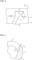
FIG. 4 is a partially enlarged sectional view of the suction slit, illustrating an upstream end of the suction slit according to the embodiment; -
FIG. 5 is a schematic view illustrating a nip point and the upstream end according to the embodiment; -
FIG. 6 is an enlarged sectional view of the upstream end according to the embodiment; -
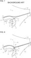
FIG. 7 is a schematic view illustrating a nip point and an upstream end according to a comparative example; -
FIG. 8 is an enlarged sectional view of an upstream end according to a modification example; and -
FIG. 9 is an enlarged sectional view of an upstream end according to another modification example. - The following will describe a fiber bundle condensing device of a spinning machine according to an embodiment of the present invention, with reference to
FIGS. 1 to 7 . -
FIG. 1 illustrates a spinning machine that includes a fiberbundle condensing device 11 and adraft device 12. Thedraft device 12 includes adelivery roller pair 13 including afront bottom roller 13a that serves as a bottom roller and afront top roller 13b that serves as a top roller. Thefront bottom roller 13a has agear portion 13c. Thedraft device 12 drafts a fiber bundle F, and thedelivery roller pair 13 delivers the fiber bundle F toward the fiberbundle condensing device 11. - The fiber
bundle condensing device 11 includes afeeding unit 14, asuction pipe 15, an air-permeable transport belt 16, and aguide unit 17. - The
feeding unit 14 includes arotary shaft 18, a bottom nip roller 18a, and atop nip roller 19. Therotary shaft 18 is arranged parallel to and adjacent to thefront bottom roller 13a of thedelivery roller pair 13, and the bottom nip roller 18a is rotatable together with therotary shaft 18. Therotary shaft 18 has agear 22 that is rotatable together with therotary shaft 18. Thegear portion 13c of thefront bottom roller 13a and thegear 22 mesh with anintermediate gear 25. A rotational force of thefront bottom roller 13a is transferred to therotary shaft 18 via thegear portion 13c, theintermediate gear 25, and thegear 22. This causes the bottom nip roller 18a to rotate. - The
top nip roller 19 presses the bottom nip roller 18a via the air-permeable transport belt 16. Thetop nip roller 19 is supported by a weighting arm (not illustrated) via a support member 20. - The spinning machine includes a suction duct (not illustrated) that extends in the longitudinal direction of the machine frame. The
suction pipe 15 is arranged parallel to the suction duct and connected to the suction duct via aconnection pipe 26. Thesuction pipe 15 is disposed downstream of thedelivery roller pair 13 of thedraft device 12, and has asuction slit 27. - The
suction pipe 15 has aguide surface 28 in which thesuction slit 27 is formed. The air-permeable transport belt 16 is partially wound on thesuction pipe 15 to cover thesuction slit 27, and rotates so as to transport the fiber bundle F. Specifically, the rotating air-permeable transport belt 16 transports the fiber bundle F, which has been attracted and condensed onto the air-permeable transport belt 16 by air flowing into thesuction slit 27, in a transport direction V. The air-permeable transport belt 16 is made from a woven fabric that ensures appropriate air permeability, for example. - The
suction pipe 15 is disposed downstream of a nip point P1 of thedelivery roller pair 13 in the transport direction V of the fiber bundle F. Thesuction pipe 15 is disposed upstream of a nip point P2 of thefeeding unit 14 in the transport direction V of the fiber bundle F. - As illustrated in
FIGS. 1 and 2 , the outer surface of thesuction pipe 15 serves as theguide surface 28. Theguide surface 28 is an arcuate surface that is gently curved along the transport direction V and has a width in the transport direction V. Theguide surface 28 extends between the nip point P1 and the nip point P2 so as to connect the nip point P1 of thedelivery roller pair 13 and the nip point P2 of thefeeding unit 14. The fiber bundle F fed from thedelivery roller pair 13 is guided by theguide surface 28 via the air-permeable transport belt 16 from the nip point P1 of thedelivery roller pair 13 toward the nip point P2 of thefeeding unit 14. - The
suction pipe 15 has a guidesurface forming portion 15a forming theguide surface 28 and having a plate shape that is gently curved along the transport direction V of the fiber bundle F. Thesuction pipe 15 has abottom portion 15b facing the guidesurface forming portion 15a. The dimension of thebottom portion 15b is smaller than the dimension of the guidesurface forming portion 15a in the transport direction V. - The
suction pipe 15 includes a firstcurved portion 15c that connects the downstream end of the guidesurface forming portion 15a and the downstream end of thebottom portion 15b in the transport direction V. The firstcurved portion 15c is curved in an arc shape along the peripheral surface of the bottom nip roller 18a. The firstcurved portion 15c faces the peripheral surface of the bottom nip roller 18a. - The
suction pipe 15 has acurved surface portion 15f that is continuous with the upstream end of the guidesurface forming portion 15a in the transport direction V, and a secondcurved portion 15d that connects thecurved surface portion 15f and the upstream end of thebottom portion 15b. The secondcurved portion 15d is curved in an arc shape along the peripheral surface of thefront bottom roller 13a. The secondcurved portion 15d faces the peripheral surface of thefront bottom roller 13a. - The
curved surface portion 15f is disposed downstream of the nip point P1 of thedelivery roller pair 13 in the transport direction V of the fiber bundle F. Thecurved surface portion 15f faces the peripheral surface of thefront bottom roller 13a of thedelivery roller pair 13 in the transport direction V. - As illustrated in
FIGS. 2 and3 , the width direction of the suction slit 27 corresponds to the longitudinal direction of thesuction pipe 15. The suction slit 27 has anupstream end 31 and adownstream end 32 in the transport direction V, and has aguide edge 29 and aside edge 30. Theupstream end 31 extends linearly and has opposite ends in the width direction. Theguide edge 29 and theside edge 30 extend from one end and the other end of the opposite ends of theupstream end 31, respectively. Thedownstream end 32 is connected to theguide edge 29 and theside edge 30. - The
guide edge 29 is an edge for condensing the fiber bundle F. Theguide edge 29 has awide portion edge 29a continuous to theupstream end 31, and adownstream edge 29b continuous to thewide portion edge 29a and extending obliquely so as to decrease the slit width of the suction slit 27. - The direction orthogonal to the longitudinal direction of the
suction pipe 15 is defined as an orthogonal direction X. The fiber bundle F fed from thedelivery roller pair 13 passes near thecurved surface portion 15f of theguide surface 28 along the orthogonal direction X. Thedownstream edge 29b of theguide edge 29 is inclined with respect to the orthogonal direction X. After passing theguide surface 28 along the orthogonal direction X, the fiber bundle F is guided by theguide edge 29 so as to travel along thewide portion edge 29a and thedownstream edge 29b. - The
side edge 30 has astraight edge 30d extending linearly from theupstream end 31, and adownstream edge 30c continuous to thestraight edge 30d. Thestraight edge 30d extends linearly and parallel to the orthogonal direction X. Thedownstream edge 30c is inclined with respect to the orthogonal direction X. - The slit width of the suction slit 27 is gradually increased by the
wide portion edge 29a and thestraight edge 30d from upstream to downstream in the transport direction V, and the slit width is then gradually decreased by thedownstream edge 29b and thestraight edge 30d. Then, the slit width is made to be substantially constant by thedownstream edge 29b of theguide edge 29 and thedownstream edge 30c of theside edge 30. - In the suction slit 27, the ratio of the
wide portion edge 29a to thedownstream edge 29b of theguide edge 29, and the ratio of thestraight edge 30d to thedownstream edge 30c of theside edge 30 or the ratio of thestraight edge 30d to theside edge 30 are appropriately determined depending on the inclination of theguide edge 29 or the required quality of the yarn to be spun. - The suction slit 27 is formed in the
suction pipe 15, and theupstream end 31 of the suction slit 27 is then formed in thesuction pipe 15 with an end mill. Specifically, theupstream end 31 is formed by moving the end mill in the width direction of the suction slit 27 with the end mill in contact with theupstream end 31. - As illustrated in
FIG. 4 , theupstream end 31 of the suction slit 27 is formed in thecurved surface portion 15f. Theupstream end 31 has anintersecting surface 31a, aflow expansion surface 31b, anintroduction surface 31c, and an arcuate surface 31f. The intersectingsurface 31a, theflow expansion surface 31b, theintroduction surface 31c, and the arcuate surface 31f extend over the wholeupstream end 31 in the longitudinal direction of thesuction pipe 15. Theflow expansion surface 31b is formed by machining the inner surface of thesuction pipe 15. Theflow expansion surface 31b may be formed while the intersectingsurface 31a is formed. Accordingly, theflow expansion surface 31b may be easily formed. - The
introduction surface 31c is smoothly continuous to the outer surface of thesuction pipe 15 via the arcuate surface 31f. Theintroduction surface 31c is an inclined surface that is a flat surface and inclined downward in the transport direction V of the fiber bundle F and forms theupstream end 31. - As illustrated in
FIGS. 5 and 6 , a first imaginary line D1 extends along theintroduction surface 31c in the orthogonal direction X. The first imaginary line D1 is located on thefront bottom roller 13a side under a common tangent L at the nip point P1. Specifically, the first imaginary line D1 is located on thebottom portion 15b side of thesuction pipe 15 under the common tangent L. The common tangent L extends in a common tangent direction R. The direction in which the first imaginary line D1 extends corresponds to the common tangent direction R. That is, theintroduction surface 31c extends in the common tangent direction R. Theintroduction surface 31c is located on thefront bottom roller 13a side under the common tangent L to thedelivery roller pair 13 at the nip point P1, and defines a flow path of the air to introduce the air to the suction slit 27. Accordingly, the first imaginary line D1 is located on thefront bottom roller 13a side under the common tangent L. - A first angle θ1 is an angle between the first imaginary line D1 along the
introduction surface 31c and the common tangent L. In this embodiment, the first angle θ1 is 0 degrees and therefore not illustrated inFIGS. 5 and 6 . If the first angle θ1 is increased, theintroduction surface 31c reaches the inner surface of thesuction pipe 15, so that the intersectingsurface 31a and theflow expansion surface 31b cannot be formed. Accordingly, the maximum value of the first angle θ1 is set to a value that allows the formation of the intersectingsurface 31a and theflow expansion surface 31b. - If the first angle θ1 is decreased to 0 degrees, which is the minimum value of the first angle θ1, the first imaginary line D1 and the common tangent L become parallel to each other. When the first angle θ1 is 0 degrees, the direction in which the air flows along the
introduction surface 31c corresponds to the common tangent direction R. This allows the air to flow along the transport direction V of the fiber bundle F fed from the nip point P1 for more quick attraction of the fiber bundle F to the air-permeable transport belt 16. That is, in the present embodiment, the first angle θ1 is 0 degrees. - The
flow expansion surface 31b is a flat surface obliquely intersecting theintroduction surface 31c. Theflow expansion surface 31b is located between the outer surface and the inner surface of thesuction pipe 15, and expands the flow path defined by theintroduction surface 31c. Theintroduction surface 31c is located on thefront bottom roller 13a side under the common tangent L, and theflow expansion surface 31b, which is continuous with theintroduction surface 31c, is located on thefront bottom roller 13a side under the common tangent L. Theflow expansion surface 31b extends from theintroduction surface 31c so as to become away from the common tangent L. - A second imaginary line D2 extends along the
flow expansion surface 31b in the orthogonal direction X. The direction in which the second imaginary line D2 extends intersects the common tangent direction R. A second angle θ2 is an angle between the second imaginary line D2 along theflow expansion surface 31b and the common tangent L. The second angle θ2 is greater than the first angle θ1. In other words, the first angle θ1 is smaller than the second angle θ2. - Decreasing the second angle θ2 may eliminate the
intersecting surface 31a. Accordingly, the minimum value of the second angle θ2 is determined so as to ensure formulation of the intersectingsurface 31a. Increasing the second angle θ2 causes theintersecting surface 31a to extend toward the outer surface of thesuction pipe 15, thereby forming a recess that is formed between theflow expansion surface 31b and the intersectingsurface 31a and recessed toward the outer surface of thesuction pipe 15. This configuration may cause an undesirable swirling airflow in the recess. Accordingly, the second angle θ2 is preferably determined so that the intersectingsurface 31a and theflow expansion surface 31b are perpendicular to each other. - The intersecting
surface 31a intersects the inner surface of thesuction pipe 15. The intersectingsurface 31a is a flat surface perpendicular to theflow expansion surface 31b. That is, the intersectingsurface 31a is perpendicular to theflow expansion surface 31b, and extends from the inner surface of thesuction pipe 15 to theflow expansion surface 31b. Thesuction pipe 15 has on the inner surface of thecurved surface portion 15f a step formed by the intersectingsurface 31a and theflow expansion surface 31b. - When the spinning machine operates, the fiber bundle F is drafted by the
draft device 12 and fed from thedelivery roller pair 13 toward the fiberbundle condensing device 11. As illustrated inFIG. 5 , the fiber bundle F is fed from thedelivery roller pair 13 along the common tangent L. The fiber bundle F is drawn via thesuction pipe 15 such that the fiber bundle F is carried from the nip point P1 of thedelivery roller pair 13 toward the nip point P2 of thefeeding unit 14, and attracted onto the air-permeable transport belt 16. The fiber bundle F is then guided by theguide surface 28 via the air-permeable transport belt 16, and carried in the transport direction V by the air-permeable transport belt 16. - The following will describe an
upstream end 71 according to a comparative example. - As illustrated in
FIG. 7 , air drawn via a suction duct flows toward theupstream end 71 of the suction slit 27 as indicated by an arrow Y. Theupstream end 71 of the comparative example has aflat surface 71a extending from the outer surface of thesuction pipe 15 to the inner surface of thesuction pipe 15. Theflat surface 71a of theupstream end 71 is located on thefront bottom roller 13a side under the common tangent L, but does not have theflow expansion surface 31b and the intersectingsurface 31a. Accordingly, the air flows along theflat surface 71a of theupstream end 71 of the comparative example in the common tangent direction R. This causes the air to swirl in a region W between the inner surface of thesuction pipe 15 and the flow of the air. The swirling air causes a decrease in the flow velocity of the air near the inner surface of thesuction pipe 15. Accordingly, in the comparative example, the fiber bundle F fed from thedelivery roller pair 13 is attracted onto the air-permeable transport belt 16 at a position on the fronttop roller 13b side above the common tangent L. - Next, the following will describe the operation of the
upstream end 31 of the embodiment of the present invention in comparison with the operation of theupstream end 71 of the comparative example. - According to the embodiment of the present invention, as illustrated in
FIG. 6 , the air drawn via the suction duct flows toward theupstream end 31 of the suction slit 27 as indicated by the arrow Y. Theintroduction surface 31c of theupstream end 31 is located on thefront bottom roller 13a side under the common tangent L. This configuration increases the amount of the air flowing into the suction slit 27 compared with a configuration in which theintroduction surface 31c is located on the fronttop roller 13b side above the common tangent L. - Furthermore, the flow path of the air defined by the
introduction surface 31c so that the air flows along theintroduction surface 31c is then expanded by theflow expansion surface 31b. Accordingly, theflow expansion surface 31b causes the air, which has flowed along theintroduction surface 31c, to flow away from the common tangent L. That is, the flow path of the air flowed along theintroduction surface 31c is expanded by theflow expansion surface 31b. This configuration allows the air to swirl in the region W between the flow of the air flowing through the expanded flow path and the inner surface of thesuction pipe 15, but reduces the region W compared with the region W of the comparative example. Accordingly, this configuration suppresses a decrease in the flow velocity of the air even if the air swirls inside thesuction pipe 15. The fiber bundle F fed from thedelivery roller pair 13 is attracted onto the air-permeable transport belt 16 near the intersection of the common tangent L and the second imaginary line D2. This allows the fiber bundle F fed from thedelivery roller pair 13 to be quickly attracted onto the air-permeable transport belt 16, compared with the configuration of the comparative example in which the fiber bundle F fed from thedelivery roller pair 13 is attracted onto the air-permeable transport belt 16 at a position on the fronttop roller 13b side above the common tangent L. This therefore allows a decrease in a distance from thedelivery roller pair 13 to the air-permeable transport belt 16, where the fiber bundle F is free. - The present embodiment obtains the following effects.
- (1) The presence of the
introduction surface 31c located on thefront bottom roller 13a side under the common tangent L increases the amount of the air flowing into the suction slit 27. Furthermore, the presence of theflow expansion surface 31b reduces the region W in which the air swirls along the inner surface of thesuction pipe 15. Accordingly, theupstream end 31 of the suction slit 27 allows an increase in the amount of the air flowing into the suction slit 27 and suppresses a decrease in the flow velocity due to the swirling of the air, thereby allowing the fiber bundle F to be quickly attracted onto the air-permeable transport belt 16. This therefore allows a decrease in a distance from thedelivery roller pair 13 to the air-permeable transport belt 16, where the fiber bundle F is free, thereby suppressing the fiber disorder in the fiber bundle F. - (2) The
introduction surface 31c introduces the air flowing in the common tangent direction R into the suction slit 27. This configuration allows an increase in the amount of the air flowing into the suction slit 27, compared with the configuration without theintroduction surface 31c. This configuration therefore allows the fiber bundle F to be quickly attracted onto the air-permeable transport belt 16 and easily condensed. Furthermore, the presence of theflow expansion surface 31b reduces the region W in which the air swirls. Accordingly, the configuration including theintroduction surface 31c and theflow expansion surface 31b generates a suction force, which quickly attracts and condenses the fiber bundle F, without increasing power consumption. - (3) The
upstream end 31 allows the fiber bundle F fed from thedelivery roller pair 13 to be quickly attracted onto the air-permeable transport belt 16. This stabilizes the quality of the yarn produced from the fiber bundle F. - (4) One way of quickly attracting the fiber bundle F fed from the
delivery roller pair 13 onto the air-permeable transport belt 16 is to place thesuction pipe 15 near thefront bottom roller 13a. However, the fiber bundle F may wrap around thefront bottom roller 13a for some reason. If thesuction pipe 15 is too close to thefront bottom roller 13a, the fiber bundle F wrapping around thefront bottom roller 13a may get jammed. The presence of theintroduction surface 31c and theflow expansion surface 31b of theupstream end 31 allows the fiber bundle F fed from thedelivery roller pair 13 to be quickly attracted onto the air-permeable transport belt 16 without placing thesuction pipe 15 near thefront bottom roller 13a. - (5) The
introduction surface 31c is an inclined surface intersecting theflow expansion surface 31b. Accordingly, theintroduction surface 31c efficiently introduces the air into the suction slit 27. - (6) The
introduction surface 31c is a flat inclined surface. This configuration allows the air to be more efficiently introduced into the suction slit 27, compared with a configuration in which theintroduction surface 31c is a curved inclined surface, for example. - The present embodiment may be modified in various manners, as exemplified below. The present embodiment and the following modification examples may be combined within the scope of the present invention.
- ∘ The
upstream end 31 of the suction slit 27 extends linearly in the longitudinal direction of thesuction pipe 15. However, the shape of theupstream end 31 is not limited thereto, and theupstream end 31 may extend obliquely to the orthogonal direction X, for example. - ∘ The air-
permeable transport belt 16 is made from a woven fabric. However, the air-permeable transport belt 16 may be made from a knitting fabric, or a rubber belt or an elastic plastic belt having a large number of holes. - ∘ As illustrated in
FIG. 8 , theintroduction surface 31c may be formed of a surface that defines a throughhole 33 penetrating thecurved surface portion 15f in the thickness direction of thecurved surface portion 15f. - ∘ As illustrated in
FIG. 9 , the first angle θ1 between the common tangent L and the first imaginary line D1 may be greater than 0 degrees as long as the first angle θ1 is smaller than the second angle θ2. - ∘ The second angle θ2 may be modified as appropriate as long as the second angle θ2 is greater than the first angle θ1.
- ∘ The
upstream end 31 may not have the intersectingsurface 31a that intersects the inner surface of thesuction pipe 15. In this configuration, theflow expansion surface 31b is formed along the inner surface of thesuction pipe 15. - ∘ The intersecting
surface 31a does not need to be perpendicular to theflow expansion surface 31b as long as the intersectingsurface 31a intersects theflow expansion surface 31b.
Claims (5)
- A fiber bundle condensing device (11) of a spinning machine, the fiber bundle condensing device (11) comprising:a suction pipe (15) disposed downstream of a delivery roller pair (13) including a bottom roller (13a) and a top roller (13b) and having a suction slit (27); andan air-permeable transport belt (16) wound on the suction pipe (15) to cover the suction slit (27) and configured to rotate so as to transport a fiber bundle (F) attracted and condensed onto the air-permeable transport belt (16) by air flowing into the suction slit (27), the air-permeable transport belt (16) being configured to transport the fiber bundle (F) in a transport direction (V), characterized in thatthe suction pipe (15) has a curved surface portion (15f) facing the bottom roller (13a),the suction slit (27) has an upstream end (31) in the transport direction (V),the upstream end (31) is formed in the curved surface portion (15f), and has:an introduction surface (31c) that is located on the bottom roller (13a) side under a common tangent (L) to the delivery roller pair (13) at a nip point (P1) and defines a flow path of the air to introduce the air into the suction slit (27); anda flow expansion surface (31b) obliquely intersecting the introduction surface (31c), located between an outer surface and an inner surface of the suction pipe (15), and expanding the flow path, anda first angle (θ1) between a first imaginary line (D1) along the introduction surface (31c) and the common tangent (L) is smaller than a second angle (θ2) between a second imaginary line (D2) along the flow expansion surface (31b) and the common tangent (L).
- The fiber bundle condensing device (11) of the spinning machine according to claim 1, characterized in that the introduction surface (31c) is an inclined surface that forms the upstream end (31).
- The fiber bundle condensing device (11) of the spinning machine according to claim 2, characterized in that the inclined surface is a flat surface.
- The fiber bundle condensing device (11) of the spinning machine according to claim 1 or 2, characterized in that the introduction surface (31c) extends in a common tangent direction (R).
- The fiber bundle condensing device (11) of the spinning machine according to claim 1 or 2, characterized in that the upstream end (31) has an intersecting surface (31a) that is perpendicular to the flow expansion surface (31b), and extends from the inner surface of the suction pipe (15) to the flow expansion surface (31b).
Applications Claiming Priority (1)
| Application Number | Priority Date | Filing Date | Title |
|---|---|---|---|
| JP2023089708A JP2024172164A (en) | 2023-05-31 | 2023-05-31 | Fiber bundle concentrating device for spinning machine |
Publications (2)
| Publication Number | Publication Date |
|---|---|
| EP4471195A1 true EP4471195A1 (en) | 2024-12-04 |
| EP4471195B1 EP4471195B1 (en) | 2026-03-04 |
Family
ID=90364987
Family Applications (1)
| Application Number | Title | Priority Date | Filing Date |
|---|---|---|---|
| EP24162912.0A Active EP4471195B1 (en) | 2023-05-31 | 2024-03-12 | Fiber bundle condensing device of spinning machine |
Country Status (3)
| Country | Link |
|---|---|
| EP (1) | EP4471195B1 (en) |
| JP (1) | JP2024172164A (en) |
| CN (1) | CN119061540A (en) |
Citations (3)
| Publication number | Priority date | Publication date | Assignee | Title |
|---|---|---|---|---|
| DE10106771A1 (en) * | 2001-02-12 | 2002-08-14 | Stahlecker Fritz | Spinning machine loose fibre extractor has air blower pipe and fibre suction tube directed at gap interface |
| JP2012087419A (en) | 2010-10-15 | 2012-05-10 | Toyota Industries Corp | Fiber bundle-gathering device in spinning machine |
| EP4047115A1 (en) * | 2021-02-17 | 2022-08-24 | Kabushiki Kaisha Toyota Jidoshokki | Fiber bundle condensing device of spinning machine |
Family Cites Families (6)
| Publication number | Priority date | Publication date | Assignee | Title |
|---|---|---|---|---|
| JPH0770833A (en) * | 1993-09-02 | 1995-03-14 | Murata Mach Ltd | Pneumatic spinning equipment |
| DE10036786A1 (en) * | 2000-07-28 | 2002-02-07 | Stahlecker Fritz | Condensing stage for drawn sliver, for spinning, has a steel spring clip around the base body as reinforcement to reduce wear and seal the suction slit against false air |
| DE10063727A1 (en) * | 2000-12-13 | 2002-06-20 | Stahlecker Fritz | Reinforcement for a suction channel of a fiber bundling device of a spinning machine |
| DE10252777A1 (en) * | 2002-11-07 | 2004-05-27 | Wilhelm Stahlecker Gmbh | Condenser for drawn slivers, at a drawing unit, has a reinforcement over the suction channel openings as C-shaped clips with a suction slit opening, for fitting and removal without tools |
| JP4821644B2 (en) * | 2007-02-21 | 2011-11-24 | 株式会社豊田自動織機 | Spinning machine |
| CH715157A1 (en) * | 2018-07-09 | 2020-01-15 | Rieter Ag Maschf | Drafting system of a ring spinning machine with a compacting zone. |
-
2023
- 2023-05-31 JP JP2023089708A patent/JP2024172164A/en active Pending
-
2024
- 2024-03-12 EP EP24162912.0A patent/EP4471195B1/en active Active
- 2024-04-10 CN CN202410427189.6A patent/CN119061540A/en active Pending
Patent Citations (3)
| Publication number | Priority date | Publication date | Assignee | Title |
|---|---|---|---|---|
| DE10106771A1 (en) * | 2001-02-12 | 2002-08-14 | Stahlecker Fritz | Spinning machine loose fibre extractor has air blower pipe and fibre suction tube directed at gap interface |
| JP2012087419A (en) | 2010-10-15 | 2012-05-10 | Toyota Industries Corp | Fiber bundle-gathering device in spinning machine |
| EP4047115A1 (en) * | 2021-02-17 | 2022-08-24 | Kabushiki Kaisha Toyota Jidoshokki | Fiber bundle condensing device of spinning machine |
Also Published As
| Publication number | Publication date |
|---|---|
| JP2024172164A (en) | 2024-12-12 |
| CN119061540A (en) | 2024-12-03 |
| EP4471195B1 (en) | 2026-03-04 |
Similar Documents
| Publication | Publication Date | Title |
|---|---|---|
| US4315398A (en) | Open-end spinning apparatus | |
| KR0163581B1 (en) | A transfer apparatus for paper web and its method | |
| JP2000034631A (en) | Apparatus for condensing drafted fiber strands | |
| JPS6131207B2 (en) | ||
| EP4471195B1 (en) | Fiber bundle condensing device of spinning machine | |
| JPS6214648B2 (en) | ||
| JPH081338U (en) | Web drying equipment | |
| CN114941190B (en) | Fiber bundle bundling device of textile machine | |
| EP1486603A1 (en) | Needle blade roll for quasi-cotton producing device | |
| US4606187A (en) | Fiber feeding air flow arrangement for open-end friction spinning | |
| JP5098880B2 (en) | Fiber bundle concentrator in spinning machine | |
| US5996181A (en) | Apparatus for bundling a drafted roving | |
| CN112543824B (en) | Machines, systems and methods for making random fiber webs | |
| JP2012087419A (en) | Fiber bundle-gathering device in spinning machine | |
| JP2004107808A (en) | Spindle fiber bundle concentrator | |
| US5778653A (en) | Suction roller for an open-end spinning machine | |
| JPS59192731A (en) | Spinning apparatus | |
| JP3826864B2 (en) | Fiber bundle focusing device in spinning machine | |
| JP2002212828A (en) | Spinning device | |
| US7007348B2 (en) | Machine for making a non-woven material by aerological means using a decreasing air flow | |
| US4744210A (en) | Method and device for producing a twisted thread from spinning fibers | |
| JP7330494B2 (en) | Paper sheet conveying device | |
| WO2003078719A1 (en) | Quasi-cotton producing device | |
| CN1338534A (en) | Spinning apparatus with condenser | |
| JP2005023430A (en) | Fiber bundle focusing device |
Legal Events
| Date | Code | Title | Description |
|---|---|---|---|
| PUAI | Public reference made under article 153(3) epc to a published international application that has entered the european phase |
Free format text: ORIGINAL CODE: 0009012 |
|
| STAA | Information on the status of an ep patent application or granted ep patent |
Free format text: STATUS: REQUEST FOR EXAMINATION WAS MADE |
|
| 17P | Request for examination filed |
Effective date: 20240312 |
|
| AK | Designated contracting states |
Kind code of ref document: A1 Designated state(s): AL AT BE BG CH CY CZ DE DK EE ES FI FR GB GR HR HU IE IS IT LI LT LU LV MC ME MK MT NL NO PL PT RO RS SE SI SK SM TR |
|
| GRAP | Despatch of communication of intention to grant a patent |
Free format text: ORIGINAL CODE: EPIDOSNIGR1 |
|
| STAA | Information on the status of an ep patent application or granted ep patent |
Free format text: STATUS: GRANT OF PATENT IS INTENDED |
|
| INTG | Intention to grant announced |
Effective date: 20251008 |
|
| GRAS | Grant fee paid |
Free format text: ORIGINAL CODE: EPIDOSNIGR3 |
|
| GRAA | (expected) grant |
Free format text: ORIGINAL CODE: 0009210 |
|
| STAA | Information on the status of an ep patent application or granted ep patent |
Free format text: STATUS: THE PATENT HAS BEEN GRANTED |
|
| AK | Designated contracting states |
Kind code of ref document: B1 Designated state(s): AL AT BE BG CH CY CZ DE DK EE ES FI FR GB GR HR HU IE IS IT LI LT LU LV MC ME MK MT NL NO PL PT RO RS SE SI SK SM TR |
|
| REG | Reference to a national code |
Ref country code: CH Ref legal event code: F10 Free format text: ST27 STATUS EVENT CODE: U-0-0-F10-F00 (AS PROVIDED BY THE NATIONAL OFFICE) Effective date: 20260304 Ref country code: GB Ref legal event code: FG4D |
|
| REG | Reference to a national code |
Ref country code: CH Ref legal event code: R17 Free format text: ST27 STATUS EVENT CODE: U-0-0-R10-R17 (AS PROVIDED BY THE NATIONAL OFFICE) Effective date: 20260309 |
|
| REG | Reference to a national code |
Ref country code: IE Ref legal event code: FG4D |
|
| REG | Reference to a national code |
Ref country code: DE Ref legal event code: R096 Ref document number: 602024002890 Country of ref document: DE |
|
| PGFP | Annual fee paid to national office [announced via postgrant information from national office to epo] |
Ref country code: AT Payment date: 20260303 Year of fee payment: 3 |
|
| P01 | Opt-out of the competence of the unified patent court (upc) registered |
Free format text: CASE NUMBER: UPC_APP_0016032_4471195/2026 Effective date: 20260520 |
|
| PG25 | Lapsed in a contracting state [announced via postgrant information from national office to epo] |
Ref country code: RS Free format text: LAPSE BECAUSE OF FAILURE TO SUBMIT A TRANSLATION OF THE DESCRIPTION OR TO PAY THE FEE WITHIN THE PRESCRIBED TIME-LIMIT Effective date: 20260604 |
|
| PG25 | Lapsed in a contracting state [announced via postgrant information from national office to epo] |
Ref country code: ES Free format text: LAPSE BECAUSE OF FAILURE TO SUBMIT A TRANSLATION OF THE DESCRIPTION OR TO PAY THE FEE WITHIN THE PRESCRIBED TIME-LIMIT Effective date: 20260304 |
|
| REG | Reference to a national code |
Ref country code: NL Ref legal event code: MP Effective date: 20260304 |
|
| PG25 | Lapsed in a contracting state [announced via postgrant information from national office to epo] |
Ref country code: PL Free format text: LAPSE BECAUSE OF FAILURE TO SUBMIT A TRANSLATION OF THE DESCRIPTION OR TO PAY THE FEE WITHIN THE PRESCRIBED TIME-LIMIT Effective date: 20260304 |
|
| PG25 | Lapsed in a contracting state [announced via postgrant information from national office to epo] |
Ref country code: GR Free format text: LAPSE BECAUSE OF FAILURE TO SUBMIT A TRANSLATION OF THE DESCRIPTION OR TO PAY THE FEE WITHIN THE PRESCRIBED TIME-LIMIT Effective date: 20260605 |
|
| REG | Reference to a national code |
Ref country code: LT Ref legal event code: MG9D |
|
| PG25 | Lapsed in a contracting state [announced via postgrant information from national office to epo] |
Ref country code: LT Free format text: LAPSE BECAUSE OF FAILURE TO SUBMIT A TRANSLATION OF THE DESCRIPTION OR TO PAY THE FEE WITHIN THE PRESCRIBED TIME-LIMIT Effective date: 20260304 |
|
| PGFP | Annual fee paid to national office [announced via postgrant information from national office to epo] |
Ref country code: DE Payment date: 20260410 Year of fee payment: 3 |
|
| PG25 | Lapsed in a contracting state [announced via postgrant information from national office to epo] |
Ref country code: NO Free format text: LAPSE BECAUSE OF FAILURE TO SUBMIT A TRANSLATION OF THE DESCRIPTION OR TO PAY THE FEE WITHIN THE PRESCRIBED TIME-LIMIT Effective date: 20260604 |
|
| PG25 | Lapsed in a contracting state [announced via postgrant information from national office to epo] |
Ref country code: SE Free format text: LAPSE BECAUSE OF FAILURE TO SUBMIT A TRANSLATION OF THE DESCRIPTION OR TO PAY THE FEE WITHIN THE PRESCRIBED TIME-LIMIT Effective date: 20260304 Ref country code: FI Free format text: LAPSE BECAUSE OF FAILURE TO SUBMIT A TRANSLATION OF THE DESCRIPTION OR TO PAY THE FEE WITHIN THE PRESCRIBED TIME-LIMIT Effective date: 20260304 |
|
| PG25 | Lapsed in a contracting state [announced via postgrant information from national office to epo] |
Ref country code: HR Free format text: LAPSE BECAUSE OF FAILURE TO SUBMIT A TRANSLATION OF THE DESCRIPTION OR TO PAY THE FEE WITHIN THE PRESCRIBED TIME-LIMIT Effective date: 20260304 |
|
| PG25 | Lapsed in a contracting state [announced via postgrant information from national office to epo] |
Ref country code: LV Free format text: LAPSE BECAUSE OF FAILURE TO SUBMIT A TRANSLATION OF THE DESCRIPTION OR TO PAY THE FEE WITHIN THE PRESCRIBED TIME-LIMIT Effective date: 20260304 |
|
| PG25 | Lapsed in a contracting state [announced via postgrant information from national office to epo] |
Ref country code: BG Free format text: LAPSE BECAUSE OF FAILURE TO SUBMIT A TRANSLATION OF THE DESCRIPTION OR TO PAY THE FEE WITHIN THE PRESCRIBED TIME-LIMIT Effective date: 20260304 |