EP4470740A1 - Generativ gefertigtes graphitwerkzeug - Google Patents
Generativ gefertigtes graphitwerkzeug Download PDFInfo
- Publication number
- EP4470740A1 EP4470740A1 EP24175838.2A EP24175838A EP4470740A1 EP 4470740 A1 EP4470740 A1 EP 4470740A1 EP 24175838 A EP24175838 A EP 24175838A EP 4470740 A1 EP4470740 A1 EP 4470740A1
- Authority
- EP
- European Patent Office
- Prior art keywords
- tooling fixture
- carbon
- tooling
- containing ink
- fixture
- Prior art date
- Legal status (The legal status is an assumption and is not a legal conclusion. Google has not performed a legal analysis and makes no representation as to the accuracy of the status listed.)
- Pending
Links
Images


Classifications
-
- B—PERFORMING OPERATIONS; TRANSPORTING
- B33—ADDITIVE MANUFACTURING TECHNOLOGY
- B33Y—ADDITIVE MANUFACTURING, i.e. MANUFACTURING OF THREE-DIMENSIONAL [3D] OBJECTS BY ADDITIVE DEPOSITION, ADDITIVE AGGLOMERATION OR ADDITIVE LAYERING, e.g. BY 3D PRINTING, STEREOLITHOGRAPHY OR SELECTIVE LASER SINTERING
- B33Y80/00—Products made by additive manufacturing
-
- B—PERFORMING OPERATIONS; TRANSPORTING
- B28—WORKING CEMENT, CLAY, OR STONE
- B28B—SHAPING CLAY OR OTHER CERAMIC COMPOSITIONS; SHAPING SLAG; SHAPING MIXTURES CONTAINING CEMENTITIOUS MATERIAL, e.g. PLASTER
- B28B1/00—Producing shaped prefabricated articles from the material
- B28B1/001—Rapid manufacturing of 3D objects by additive depositing, agglomerating or laminating of material
-
- B—PERFORMING OPERATIONS; TRANSPORTING
- B28—WORKING CEMENT, CLAY, OR STONE
- B28B—SHAPING CLAY OR OTHER CERAMIC COMPOSITIONS; SHAPING SLAG; SHAPING MIXTURES CONTAINING CEMENTITIOUS MATERIAL, e.g. PLASTER
- B28B7/00—Moulds; Cores; Mandrels
- B28B7/34—Moulds, cores, or mandrels of special material, e.g. destructible materials
- B28B7/346—Manufacture of moulds
-
- B—PERFORMING OPERATIONS; TRANSPORTING
- B29—WORKING OF PLASTICS; WORKING OF SUBSTANCES IN A PLASTIC STATE IN GENERAL
- B29C—SHAPING OR JOINING OF PLASTICS; SHAPING OF MATERIAL IN A PLASTIC STATE, NOT OTHERWISE PROVIDED FOR; AFTER-TREATMENT OF THE SHAPED PRODUCTS, e.g. REPAIRING
- B29C64/00—Additive manufacturing, i.e. manufacturing of three-dimensional [3D] objects by additive deposition, additive agglomeration or additive layering, e.g. by 3D printing, stereolithography or selective laser sintering
- B29C64/10—Processes of additive manufacturing
- B29C64/165—Processes of additive manufacturing using a combination of solid and fluid materials, e.g. a powder selectively bound by a liquid binder, catalyst, inhibitor or energy absorber
-
- B—PERFORMING OPERATIONS; TRANSPORTING
- B33—ADDITIVE MANUFACTURING TECHNOLOGY
- B33Y—ADDITIVE MANUFACTURING, i.e. MANUFACTURING OF THREE-DIMENSIONAL [3D] OBJECTS BY ADDITIVE DEPOSITION, ADDITIVE AGGLOMERATION OR ADDITIVE LAYERING, e.g. BY 3D PRINTING, STEREOLITHOGRAPHY OR SELECTIVE LASER SINTERING
- B33Y10/00—Processes of additive manufacturing
-
- B—PERFORMING OPERATIONS; TRANSPORTING
- B33—ADDITIVE MANUFACTURING TECHNOLOGY
- B33Y—ADDITIVE MANUFACTURING, i.e. MANUFACTURING OF THREE-DIMENSIONAL [3D] OBJECTS BY ADDITIVE DEPOSITION, ADDITIVE AGGLOMERATION OR ADDITIVE LAYERING, e.g. BY 3D PRINTING, STEREOLITHOGRAPHY OR SELECTIVE LASER SINTERING
- B33Y40/00—Auxiliary operations or equipment, e.g. for material handling
- B33Y40/20—Post-treatment, e.g. curing, coating or polishing
-
- C—CHEMISTRY; METALLURGY
- C01—INORGANIC CHEMISTRY
- C01B—NON-METALLIC ELEMENTS; COMPOUNDS THEREOF; METALLOIDS OR COMPOUNDS THEREOF NOT COVERED BY SUBCLASS C01C
- C01B32/00—Carbon; Compounds thereof
- C01B32/20—Graphite
- C01B32/21—After-treatment
-
- C—CHEMISTRY; METALLURGY
- C04—CEMENTS; CONCRETE; ARTIFICIAL STONE; CERAMICS; REFRACTORIES
- C04B—LIME, MAGNESIA; SLAG; CEMENTS; COMPOSITIONS THEREOF, e.g. MORTARS, CONCRETE OR LIKE BUILDING MATERIALS; ARTIFICIAL STONE; CERAMICS; REFRACTORIES; TREATMENT OF NATURAL STONE
- C04B35/00—Shaped ceramic products characterised by their composition; Ceramics compositions; Processing powders of inorganic compounds preparatory to the manufacturing of ceramic products
- C04B35/515—Shaped ceramic products characterised by their composition; Ceramics compositions; Processing powders of inorganic compounds preparatory to the manufacturing of ceramic products based on non-oxide ceramics
- C04B35/52—Shaped ceramic products characterised by their composition; Ceramics compositions; Processing powders of inorganic compounds preparatory to the manufacturing of ceramic products based on non-oxide ceramics based on carbon, e.g. graphite
- C04B35/522—Graphite
-
- C—CHEMISTRY; METALLURGY
- C04—CEMENTS; CONCRETE; ARTIFICIAL STONE; CERAMICS; REFRACTORIES
- C04B—LIME, MAGNESIA; SLAG; CEMENTS; COMPOSITIONS THEREOF, e.g. MORTARS, CONCRETE OR LIKE BUILDING MATERIALS; ARTIFICIAL STONE; CERAMICS; REFRACTORIES; TREATMENT OF NATURAL STONE
- C04B35/00—Shaped ceramic products characterised by their composition; Ceramics compositions; Processing powders of inorganic compounds preparatory to the manufacturing of ceramic products
- C04B35/622—Forming processes; Processing powders of inorganic compounds preparatory to the manufacturing of ceramic products
- C04B35/626—Preparing or treating the powders individually or as batches ; preparing or treating macroscopic reinforcing agents for ceramic products, e.g. fibres; mechanical aspects section B
- C04B35/628—Coating the powders or the macroscopic reinforcing agents
- C04B35/62844—Coating fibres
- C04B35/62857—Coating fibres with non-oxide ceramics
- C04B35/62873—Carbon
-
- C—CHEMISTRY; METALLURGY
- C04—CEMENTS; CONCRETE; ARTIFICIAL STONE; CERAMICS; REFRACTORIES
- C04B—LIME, MAGNESIA; SLAG; CEMENTS; COMPOSITIONS THEREOF, e.g. MORTARS, CONCRETE OR LIKE BUILDING MATERIALS; ARTIFICIAL STONE; CERAMICS; REFRACTORIES; TREATMENT OF NATURAL STONE
- C04B35/00—Shaped ceramic products characterised by their composition; Ceramics compositions; Processing powders of inorganic compounds preparatory to the manufacturing of ceramic products
- C04B35/71—Ceramic products containing macroscopic reinforcing agents
- C04B35/78—Ceramic products containing macroscopic reinforcing agents containing non-metallic materials
- C04B35/80—Fibres, filaments, whiskers, platelets, or the like
- C04B35/83—Carbon fibres in a carbon matrix
-
- C—CHEMISTRY; METALLURGY
- C04—CEMENTS; CONCRETE; ARTIFICIAL STONE; CERAMICS; REFRACTORIES
- C04B—LIME, MAGNESIA; SLAG; CEMENTS; COMPOSITIONS THEREOF, e.g. MORTARS, CONCRETE OR LIKE BUILDING MATERIALS; ARTIFICIAL STONE; CERAMICS; REFRACTORIES; TREATMENT OF NATURAL STONE
- C04B38/00—Porous mortars, concrete, artificial stone or ceramic ware; Preparation thereof
- C04B38/0003—Porous mortars, concrete, artificial stone or ceramic ware; Preparation thereof containing continuous channels, e.g. of the "dead-end" type or obtained by pushing bars in the green ceramic product
-
- C—CHEMISTRY; METALLURGY
- C23—COATING METALLIC MATERIAL; COATING MATERIAL WITH METALLIC MATERIAL; CHEMICAL SURFACE TREATMENT; DIFFUSION TREATMENT OF METALLIC MATERIAL; COATING BY VACUUM EVAPORATION, BY SPUTTERING, BY ION IMPLANTATION OR BY CHEMICAL VAPOUR DEPOSITION, IN GENERAL; INHIBITING CORROSION OF METALLIC MATERIAL OR INCRUSTATION IN GENERAL
- C23C—COATING METALLIC MATERIAL; COATING MATERIAL WITH METALLIC MATERIAL; SURFACE TREATMENT OF METALLIC MATERIAL BY DIFFUSION INTO THE SURFACE, BY CHEMICAL CONVERSION OR SUBSTITUTION; COATING BY VACUUM EVAPORATION, BY SPUTTERING, BY ION IMPLANTATION OR BY CHEMICAL VAPOUR DEPOSITION, IN GENERAL
- C23C16/00—Chemical coating by decomposition of gaseous compounds, without leaving reaction products of surface material in the coating, i.e. chemical vapour deposition [CVD] processes
- C23C16/04—Coating on selected surface areas, e.g. using masks
- C23C16/045—Coating cavities or hollow spaces, e.g. interior of tubes; Infiltration of porous substrates
-
- C—CHEMISTRY; METALLURGY
- C23—COATING METALLIC MATERIAL; COATING MATERIAL WITH METALLIC MATERIAL; CHEMICAL SURFACE TREATMENT; DIFFUSION TREATMENT OF METALLIC MATERIAL; COATING BY VACUUM EVAPORATION, BY SPUTTERING, BY ION IMPLANTATION OR BY CHEMICAL VAPOUR DEPOSITION, IN GENERAL; INHIBITING CORROSION OF METALLIC MATERIAL OR INCRUSTATION IN GENERAL
- C23C—COATING METALLIC MATERIAL; COATING MATERIAL WITH METALLIC MATERIAL; SURFACE TREATMENT OF METALLIC MATERIAL BY DIFFUSION INTO THE SURFACE, BY CHEMICAL CONVERSION OR SUBSTITUTION; COATING BY VACUUM EVAPORATION, BY SPUTTERING, BY ION IMPLANTATION OR BY CHEMICAL VAPOUR DEPOSITION, IN GENERAL
- C23C16/00—Chemical coating by decomposition of gaseous compounds, without leaving reaction products of surface material in the coating, i.e. chemical vapour deposition [CVD] processes
- C23C16/44—Chemical coating by decomposition of gaseous compounds, without leaving reaction products of surface material in the coating, i.e. chemical vapour deposition [CVD] processes characterised by the method of coating
- C23C16/458—Chemical coating by decomposition of gaseous compounds, without leaving reaction products of surface material in the coating, i.e. chemical vapour deposition [CVD] processes characterised by the method of coating characterised by the method used for supporting substrates in the reaction chamber
-
- C—CHEMISTRY; METALLURGY
- C04—CEMENTS; CONCRETE; ARTIFICIAL STONE; CERAMICS; REFRACTORIES
- C04B—LIME, MAGNESIA; SLAG; CEMENTS; COMPOSITIONS THEREOF, e.g. MORTARS, CONCRETE OR LIKE BUILDING MATERIALS; ARTIFICIAL STONE; CERAMICS; REFRACTORIES; TREATMENT OF NATURAL STONE
- C04B2111/00—Mortars, concrete or artificial stone or mixtures to prepare them, characterised by specific function, property or use
- C04B2111/00034—Physico-chemical characteristics of the mixtures
- C04B2111/00181—Mixtures specially adapted for three-dimensional printing (3DP), stereo-lithography or prototyping
-
- C—CHEMISTRY; METALLURGY
- C04—CEMENTS; CONCRETE; ARTIFICIAL STONE; CERAMICS; REFRACTORIES
- C04B—LIME, MAGNESIA; SLAG; CEMENTS; COMPOSITIONS THEREOF, e.g. MORTARS, CONCRETE OR LIKE BUILDING MATERIALS; ARTIFICIAL STONE; CERAMICS; REFRACTORIES; TREATMENT OF NATURAL STONE
- C04B2235/00—Aspects relating to ceramic starting mixtures or sintered ceramic products
- C04B2235/02—Composition of constituents of the starting material or of secondary phases of the final product
- C04B2235/30—Constituents and secondary phases not being of a fibrous nature
- C04B2235/42—Non metallic elements added as constituents or additives, e.g. sulfur, phosphor, selenium or tellurium
- C04B2235/422—Carbon
- C04B2235/425—Graphite
-
- C—CHEMISTRY; METALLURGY
- C04—CEMENTS; CONCRETE; ARTIFICIAL STONE; CERAMICS; REFRACTORIES
- C04B—LIME, MAGNESIA; SLAG; CEMENTS; COMPOSITIONS THEREOF, e.g. MORTARS, CONCRETE OR LIKE BUILDING MATERIALS; ARTIFICIAL STONE; CERAMICS; REFRACTORIES; TREATMENT OF NATURAL STONE
- C04B2235/00—Aspects relating to ceramic starting mixtures or sintered ceramic products
- C04B2235/02—Composition of constituents of the starting material or of secondary phases of the final product
- C04B2235/50—Constituents or additives of the starting mixture chosen for their shape or used because of their shape or their physical appearance
- C04B2235/52—Constituents or additives characterised by their shapes
- C04B2235/5208—Fibers
- C04B2235/5216—Inorganic
- C04B2235/524—Non-oxidic, e.g. borides, carbides, silicides or nitrides
- C04B2235/5248—Carbon, e.g. graphite
-
- C—CHEMISTRY; METALLURGY
- C04—CEMENTS; CONCRETE; ARTIFICIAL STONE; CERAMICS; REFRACTORIES
- C04B—LIME, MAGNESIA; SLAG; CEMENTS; COMPOSITIONS THEREOF, e.g. MORTARS, CONCRETE OR LIKE BUILDING MATERIALS; ARTIFICIAL STONE; CERAMICS; REFRACTORIES; TREATMENT OF NATURAL STONE
- C04B2235/00—Aspects relating to ceramic starting mixtures or sintered ceramic products
- C04B2235/02—Composition of constituents of the starting material or of secondary phases of the final product
- C04B2235/50—Constituents or additives of the starting mixture chosen for their shape or used because of their shape or their physical appearance
- C04B2235/52—Constituents or additives characterised by their shapes
- C04B2235/5208—Fibers
- C04B2235/5252—Fibers having a specific pre-form
-
- C—CHEMISTRY; METALLURGY
- C04—CEMENTS; CONCRETE; ARTIFICIAL STONE; CERAMICS; REFRACTORIES
- C04B—LIME, MAGNESIA; SLAG; CEMENTS; COMPOSITIONS THEREOF, e.g. MORTARS, CONCRETE OR LIKE BUILDING MATERIALS; ARTIFICIAL STONE; CERAMICS; REFRACTORIES; TREATMENT OF NATURAL STONE
- C04B2235/00—Aspects relating to ceramic starting mixtures or sintered ceramic products
- C04B2235/60—Aspects relating to the preparation, properties or mechanical treatment of green bodies or pre-forms
- C04B2235/602—Making the green bodies or pre-forms by moulding
- C04B2235/6021—Extrusion moulding
-
- C—CHEMISTRY; METALLURGY
- C04—CEMENTS; CONCRETE; ARTIFICIAL STONE; CERAMICS; REFRACTORIES
- C04B—LIME, MAGNESIA; SLAG; CEMENTS; COMPOSITIONS THEREOF, e.g. MORTARS, CONCRETE OR LIKE BUILDING MATERIALS; ARTIFICIAL STONE; CERAMICS; REFRACTORIES; TREATMENT OF NATURAL STONE
- C04B2235/00—Aspects relating to ceramic starting mixtures or sintered ceramic products
- C04B2235/60—Aspects relating to the preparation, properties or mechanical treatment of green bodies or pre-forms
- C04B2235/602—Making the green bodies or pre-forms by moulding
- C04B2235/6026—Computer aided shaping, e.g. rapid prototyping
-
- C—CHEMISTRY; METALLURGY
- C04—CEMENTS; CONCRETE; ARTIFICIAL STONE; CERAMICS; REFRACTORIES
- C04B—LIME, MAGNESIA; SLAG; CEMENTS; COMPOSITIONS THEREOF, e.g. MORTARS, CONCRETE OR LIKE BUILDING MATERIALS; ARTIFICIAL STONE; CERAMICS; REFRACTORIES; TREATMENT OF NATURAL STONE
- C04B2235/00—Aspects relating to ceramic starting mixtures or sintered ceramic products
- C04B2235/60—Aspects relating to the preparation, properties or mechanical treatment of green bodies or pre-forms
- C04B2235/602—Making the green bodies or pre-forms by moulding
- C04B2235/6028—Shaping around a core which is removed later
Definitions
- the present invention relates to the fabrication of ceramic matrix composites (CMCs), and more particularly to improved tooling for CMCs.
- CMC parts are widely fabricated by densifying preforms made from woven fabrics or oriented fiber tows.
- Chemical vapor infiltration (CVI) is one of the most commonly used densification techniques practiced in industry.
- perforated tooling can be used to hold the preforms during the initial densification cycle(s). Holes on the tooling allow gaseous precursors to infiltrate into the preform for the deposition.
- Traditional tooling can be simply designed machined graphite blocks with uniform thicknesses and hole lengths. Such tooling can be difficult to tailor to complexly-shaped preforms, thus, a need exists for improved tooling.
- a method of fabricating a tooling fixture suitable for use in infiltrating a fibrous preform includes generating a model of the tooling fixture, the model being conformal and complementary to a geometry of the fibrous preform, additively manufacturing the tooling fixture by extruding a carbon-containing ink in a layer-by-layer manner, and consolidating the extruded carbon-containing ink to form a consolidated tooling fixture.
- An additively manufactured tooling fixture suitable for use in infiltrating a fibrous preform includes a body comprising a consolidated carbon-containing ink.
- a geometry of the tooling fixture conforms to and complements a geometry of the fibrous preform.
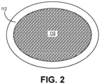
- FIGS. 1 and 2 are simplified cross-sectional illustrations of tooling fixtures 10 and 110 supporting preforms 12 and 112, respectively.
- FIG. 3 is a flowchart illustrating steps 202-208 of method 200 for fabricating tooling fixtures 10 and 110. FIGS. 1-3 are discussed together.
- Preforms 12 and 112 can each be formed from tows of silicon carbide (SiC) fibers arranged in one of various two or three-dimensional woven architectures such as plain, harness (e.g., 3, 5, 8, etc.), twill, braid, or non-symmetric to name a few non-limiting examples.
- preforms 12 and/or 112 can be formed from non-woven (e.g., chopped, felted, etc.) fibers.
- preform 12 includes a number of straight sides, and more specifically, planar portion 14 joined with hollow rectangular portion 16. variously disposed with respect to one another.
- preform 12 can be used to fabricate an air seal assembly for a gas turbine engine.
- preform 112 has a rounded geometry such that tooling fixture 110 is configured as a mandrel.
- preform 112 can be used to fabricate an airfoil of a blade or vane for a gas turbine engine.
- Other final CMC components with curved features are contemplated herein.
- a traditionally manufactured tooling fixture might be shaped as a cube or rectangular cuboid sized to enclose preform 12. Accordingly, the geometry of such a tooling fixture would not necessarily conform to the exact geometry of preform 12. This can lead to a need to form more complicated tooling designs with variously sized infiltration holes in an effort to maintain uniform flow of gaseous precursors through the tooling fixture.
- a traditionally manufactured mandrel can be difficult to sufficiently populate with infiltration holes sufficient to allow gaseous precursors to access the inner surface of preform 112 during CVI.
- Traditionally manufactured tooling fixtures can also be expensive with long lead times to fabricate.
- tooling fixtures 10 and 110 can each be tailored, using method 200, to optimize both strength and porosity, that is, the amount of open space through which gaseous precursors can diffuse, and made relatively quickly and inexpensively.
- the ability to create a conformal tooling fixture can further allow for more uniformity of the flow of gaseous precursors during CVI.
- Such conformal tooling fixtures can include straight and/or curved portions complementary to various preform geometries.
- a model of the tooling fixture to be fabricated can be generated.
- the modeling program can include topology optimization to remove as much material as possible while maintaining the requisite mechanical and thermal properties.
- the model generated at step 202 will also consider (i.e., be based on) the geometry of the corresponding preform such that the printed tooling fixture has a conformal and complementary geometry to the preform.
- the tooling fixture can be additively manufactured according to the generated model. More specifically, the tooling fixture can be printed, in one embodiment, using an extrusion-type 3D printing technique (e.g., direct-ink-writing).
- graphite ink can be used to form a graphite tooling fixture having properties (e.g., coefficient of thermal expansion) similar to traditional machined graphite tooling fixtures.
- the ink can be extruded in a layer-by-layer manner to form the tooling fixture, or portion of the tooling fixture.
- a carbon-carbon composite tooling fixture can be printed with an ink containing a slurry of short carbon fibers.
- all or portions of the tooling fixture can be printed onto a build platform and assembled, after consolidation, around the preform. In an alternative embodiment, all or portions of the tooling fixture can be printed directly onto the preform itself to form a monolithic body.
- the printed ink can be graphitized/consolidated via heat treatment.
- the resulting body can have a truss-type cellular organization forming a network of pores through which gaseous precursors can diffuse to reach the supported preform.
- the porosity can be optimized during the modeling step to achieve the ideal diffusion rate while being dense enough such that reactants do not deposit on/within the tooling fixture instead of the preform.
- the consolidated structure can resemble traditional tooling, with fairly dense solid portions, and infiltration holes, shown in dashed lines as holes 18 in FIG. 1 , variously patterned throughout and extending through the thickness of the preform at their respective locations. Holes 18 in an additively manufactured tooling fixture can be formed with complex three-dimensional shapes hard to achieve with traditional machining processes.
- the tooling fixture can be assembled around the preform. Assembly can include the use of clamps or mating features printed with the various segments to secure the tooling fixture in place.
- the enclosed/support preform can then undergo CVI to apply interface coating(s) (e.g., of boron nitride - BN) and/or infiltrate the preform with a ceramic (e.g., SiC) matrix to form the resulting CMC component.
- interface coating(s) e.g., of boron nitride - BN
- a ceramic e.g., SiC
- a CMC component formed with the aid of any of the disclosed printed tooling fixtures can be incorporated into aerospace, maritime, or industrial equipment, to name a few, non-limiting examples.
- a method of fabricating a tooling fixture suitable for use in infiltrating a fibrous preform includes generating a model of the tooling fixture, the model being conformal and complementary to a geometry of the fibrous preform, additively manufacturing the tooling fixture by extruding a carbon-containing ink in a layer-by-layer manner, and consolidating the extruded carbon-containing ink to form a consolidated tooling fixture.
- the step of generating the model can further include using topology optimization to reduce material of the tooling fixture.
- the carbon-containing ink can include graphite.
- a body of the consolidated tooling fixture can include a porous cellular network.
- a body of the consolidated tooling fixture can include a plurality of infiltration holes.
- the carbon-containing ink can include carbon fibers.
- the step of additively manufacturing the tooling fixture can include three dimensionally printing the tooling fixture.
- the step of three dimensionally printing the tooling fixture can include direct-ink-writing.
- the step of three dimensionally printing the tooling fixture can include extruding the carbon-containing ink directly onto the fibrous preform.
- the step of three dimensionally printing the tooling fixture can include extruding the carbon-containing ink onto a build platform.
- Any of the above methods can further include after consolidating the extruded carbon-containing ink, assembling the consolidated tooling fixture around the fibrous preform.
- An additively manufactured tooling fixture suitable for use in infiltrating a fibrous preform includes a body comprising a consolidated carbon-containing ink.
- a geometry of the tooling fixture conforms to and complements a geometry of the fibrous preform.
- the tooling fixture of the preceding paragraph can optionally include, additionally and/or alternatively, any one or more of the following features, configurations and/or additional components:
- the body can include graphite.
- the body can include a porous cellular network.
- the body can include a plurality of infiltration holes.
- the body can include a carbon-carbon composite material.
- At least a portion of the tooling fixture can be curved.
- At least a portion of the tooling fixture can be planar.
- the tooling fixture can include a monolithic body.
- the tooling fixture can be a mandrel.
Landscapes
- Chemical & Material Sciences (AREA)
- Engineering & Computer Science (AREA)
- Ceramic Engineering (AREA)
- Manufacturing & Machinery (AREA)
- Materials Engineering (AREA)
- Organic Chemistry (AREA)
- Mechanical Engineering (AREA)
- Structural Engineering (AREA)
- Chemical Kinetics & Catalysis (AREA)
- Inorganic Chemistry (AREA)
- Composite Materials (AREA)
- General Chemical & Material Sciences (AREA)
- Metallurgy (AREA)
- Optics & Photonics (AREA)
- General Life Sciences & Earth Sciences (AREA)
- Geology (AREA)
- Life Sciences & Earth Sciences (AREA)
- Physics & Mathematics (AREA)
- Chemical Vapour Deposition (AREA)
Applications Claiming Priority (1)
| Application Number | Priority Date | Filing Date | Title |
|---|---|---|---|
| US18/200,174 US20240391134A1 (en) | 2023-05-22 | 2023-05-22 | Additively manufactured graphite tooling |
Publications (1)
| Publication Number | Publication Date |
|---|---|
| EP4470740A1 true EP4470740A1 (de) | 2024-12-04 |
Family
ID=91082284
Family Applications (1)
| Application Number | Title | Priority Date | Filing Date |
|---|---|---|---|
| EP24175838.2A Pending EP4470740A1 (de) | 2023-05-22 | 2024-05-14 | Generativ gefertigtes graphitwerkzeug |
Country Status (2)
| Country | Link |
|---|---|
| US (1) | US20240391134A1 (de) |
| EP (1) | EP4470740A1 (de) |
Citations (3)
| Publication number | Priority date | Publication date | Assignee | Title |
|---|---|---|---|---|
| US20180346384A1 (en) * | 2015-11-24 | 2018-12-06 | Sgl Carbon Se | Plastic component comprising a carbon filler |
| FR3084893A1 (fr) * | 2018-08-07 | 2020-02-14 | Safran Ceramics | Conformateur a structure en reseau alveolaire pour la densification d’une preforme fibreuse par voie gazeuse |
| CN115181959A (zh) * | 2022-06-21 | 2022-10-14 | 西安鑫垚陶瓷复合材料有限公司 | 大型薄壁陶瓷基复合材料件加工沉积工装及加工方法、使用方法 |
Family Cites Families (10)
| Publication number | Priority date | Publication date | Assignee | Title |
|---|---|---|---|---|
| US7452735B2 (en) * | 2003-09-12 | 2008-11-18 | Applied Nanotech Holdings, Inc. | Carbon nanotube deposition with a stencil |
| US10350329B2 (en) * | 2014-10-15 | 2019-07-16 | Northwestern University | Graphene-based ink compositions for three-dimensional printing applications |
| CN111618300B (zh) * | 2014-12-12 | 2022-08-05 | 美题隆公司 | 一种制品及其形成方法 |
| EP3442772A4 (de) * | 2016-04-14 | 2019-11-13 | Desktop Metal, Inc. | Generative fertigung mit stützstrukturen |
| WO2019152022A1 (en) * | 2018-01-31 | 2019-08-08 | Hewlett-Packard Development Company, L.P. | Additive manufacturing object conductivity |
| US11015467B2 (en) * | 2018-07-06 | 2021-05-25 | Raytheon Technologies Corporation | Porous space fillers for ceramic matrix composites |
| WO2020014677A1 (en) * | 2018-07-13 | 2020-01-16 | Desktop Metal, Inc. | Infiltration barriers |
| US10928805B2 (en) * | 2018-11-15 | 2021-02-23 | Lawrence Livermore National Security, Llc | Additive manufacturing system and method having toolpath analysis |
| US11879023B2 (en) * | 2020-08-21 | 2024-01-23 | United States Of America As Represented By The Secretary Of The Air Force | Articles comprising crosslinked polymer network comprising thioether crosslinks and process of making and using same |
| US20240278507A1 (en) * | 2023-02-17 | 2024-08-22 | Lawrence Livermore National Security, Llc | Systems and Methods for Additive Manufacturing to Produce Carbon-Carbon Parts with Improved Properties and Reduced Manufacturing Times |
-
2023
- 2023-05-22 US US18/200,174 patent/US20240391134A1/en active Pending
-
2024
- 2024-05-14 EP EP24175838.2A patent/EP4470740A1/de active Pending
Patent Citations (3)
| Publication number | Priority date | Publication date | Assignee | Title |
|---|---|---|---|---|
| US20180346384A1 (en) * | 2015-11-24 | 2018-12-06 | Sgl Carbon Se | Plastic component comprising a carbon filler |
| FR3084893A1 (fr) * | 2018-08-07 | 2020-02-14 | Safran Ceramics | Conformateur a structure en reseau alveolaire pour la densification d’une preforme fibreuse par voie gazeuse |
| CN115181959A (zh) * | 2022-06-21 | 2022-10-14 | 西安鑫垚陶瓷复合材料有限公司 | 大型薄壁陶瓷基复合材料件加工沉积工装及加工方法、使用方法 |
Also Published As
| Publication number | Publication date |
|---|---|
| US20240391134A1 (en) | 2024-11-28 |
Similar Documents
| Publication | Publication Date | Title |
|---|---|---|
| JP7187094B2 (ja) | マイクロチャネルを有するcmc部品およびcmc部品内にマイクロチャネルを形成するための方法 | |
| US8607454B2 (en) | Method for producing a turbomachine blade made from a composite material | |
| EP1674599B1 (de) | Orthogonalweben zum Herstellen von Vorformen mit komplexer Form | |
| CN102099313B (zh) | 由复合材料制成的喷嘴或扩张喷嘴元件的制造方法 | |
| US20160214283A1 (en) | Composite tool and method for forming composite components | |
| CN110382444B (zh) | 用于生产固结的纤维预制件的方法 | |
| CA2747364A1 (en) | Ceramic matrix composite blade having integral platform structures and methods of fabrication | |
| US20200308066A1 (en) | Ceramic Matrix Composite Articles and Methods for Manufacturing the Same | |
| EP3459733B1 (de) | Verfahren zur erzeugung von gegenständen aus keramik-matrix-verbundwerkstoffe | |
| JP2013537595A (ja) | 相補的な非対称の幾何学的配置を有しているターボ機械ブレード | |
| US20240253333A1 (en) | Composite panels and methods for manufacturing the same | |
| EP4454842A1 (de) | Z-kanalerzeugung in einer gewebten vorform durch integration von stiftmerkmalen in ein vorformwerkzeug | |
| EP4286127B1 (de) | Eine faserige vorform mit einer vielzahl von sanduhrförmigen hohlräumen | |
| EP4470740A1 (de) | Generativ gefertigtes graphitwerkzeug | |
| US20220250992A1 (en) | Porous ceramic structure for part made of cmc material and method for obtaining same | |
| JP2009120426A (ja) | 長繊維強化セラミックス複合材料およびその製造方法 | |
| US12392037B2 (en) | Floating tooling assembly for chemical vapor infiltration | |
| US20190023618A1 (en) | Composite material and method for making | |
| US20240376017A1 (en) | Prefabricated noodle | |
| US20040115348A1 (en) | Method for processing silicon-carbide preforms having a high temperature boron nitride coating | |
| JP5862234B2 (ja) | 平滑表面を有するセラミックス基複合部材およびその製造方法 | |
| CN114835500A (zh) | 一种SiC/SiC复合材料变曲率加筋构件制备方法 | |
| JP3371993B2 (ja) | 繊維強化型セラミックス複合材料の製造方法 | |
| US12473236B2 (en) | Internal tooling configuration for the creation of z-channels in woven ceramic matrix composite preforms | |
| EP4431483A1 (de) | Dreidimensionale bindung mit sakrifiziellen z-fasern für verbesserte keramikmatrixverbundstoffmikrostruktur |
Legal Events
| Date | Code | Title | Description |
|---|---|---|---|
| PUAI | Public reference made under article 153(3) epc to a published international application that has entered the european phase |
Free format text: ORIGINAL CODE: 0009012 |
|
| STAA | Information on the status of an ep patent application or granted ep patent |
Free format text: STATUS: THE APPLICATION HAS BEEN PUBLISHED |
|
| AK | Designated contracting states |
Kind code of ref document: A1 Designated state(s): AL AT BE BG CH CY CZ DE DK EE ES FI FR GB GR HR HU IE IS IT LI LT LU LV MC ME MK MT NL NO PL PT RO RS SE SI SK SM TR |
|
| STAA | Information on the status of an ep patent application or granted ep patent |
Free format text: STATUS: REQUEST FOR EXAMINATION WAS MADE |
|
| 17P | Request for examination filed |
Effective date: 20250530 |
|
| STAA | Information on the status of an ep patent application or granted ep patent |
Free format text: STATUS: EXAMINATION IS IN PROGRESS |
|
| 17Q | First examination report despatched |
Effective date: 20250829 |