EP4470487A2 - Systems for creating permanent drainage fistula - Google Patents
Systems for creating permanent drainage fistula Download PDFInfo
- Publication number
- EP4470487A2 EP4470487A2 EP24202713.4A EP24202713A EP4470487A2 EP 4470487 A2 EP4470487 A2 EP 4470487A2 EP 24202713 A EP24202713 A EP 24202713A EP 4470487 A2 EP4470487 A2 EP 4470487A2
- Authority
- EP
- European Patent Office
- Prior art keywords
- proximal
- medical device
- distal
- tissue
- retention member
- Prior art date
- Legal status (The legal status is an assumption and is not a legal conclusion. Google has not performed a legal analysis and makes no representation as to the accuracy of the status listed.)
- Pending
Links
Images






Classifications
-
- A—HUMAN NECESSITIES
- A61—MEDICAL OR VETERINARY SCIENCE; HYGIENE
- A61M—DEVICES FOR INTRODUCING MEDIA INTO, OR ONTO, THE BODY; DEVICES FOR TRANSDUCING BODY MEDIA OR FOR TAKING MEDIA FROM THE BODY; DEVICES FOR PRODUCING OR ENDING SLEEP OR STUPOR
- A61M27/00—Drainage appliance for wounds or the like, i.e. wound drains, implanted drains
- A61M27/002—Implant devices for drainage of body fluids from one part of the body to another
-
- A—HUMAN NECESSITIES
- A61—MEDICAL OR VETERINARY SCIENCE; HYGIENE
- A61B—DIAGNOSIS; SURGERY; IDENTIFICATION
- A61B17/00—Surgical instruments, devices or methods
- A61B17/11—Surgical instruments, devices or methods for performing anastomosis; Buttons for anastomosis
-
- A—HUMAN NECESSITIES
- A61—MEDICAL OR VETERINARY SCIENCE; HYGIENE
- A61B—DIAGNOSIS; SURGERY; IDENTIFICATION
- A61B17/00—Surgical instruments, devices or methods
- A61B17/11—Surgical instruments, devices or methods for performing anastomosis; Buttons for anastomosis
- A61B17/1114—Surgical instruments, devices or methods for performing anastomosis; Buttons for anastomosis of the digestive tract, e.g. bowels or oesophagus
-
- A—HUMAN NECESSITIES
- A61—MEDICAL OR VETERINARY SCIENCE; HYGIENE
- A61F—FILTERS IMPLANTABLE INTO BLOOD VESSELS; PROSTHESES; DEVICES PROVIDING PATENCY TO, OR PREVENTING COLLAPSING OF, TUBULAR STRUCTURES OF THE BODY, e.g. STENTS; ORTHOPAEDIC, NURSING OR CONTRACEPTIVE DEVICES; FOMENTATION; TREATMENT OR PROTECTION OF EYES OR EARS; BANDAGES, DRESSINGS OR ABSORBENT PADS; FIRST-AID KITS
- A61F2/00—Filters implantable into blood vessels; Prostheses, i.e. artificial substitutes or replacements for parts of the body; Appliances for connecting them with the body; Devices providing patency to, or preventing collapsing of, tubular structures of the body, e.g. stents
- A61F2/02—Prostheses implantable into the body
- A61F2/04—Hollow or tubular parts of organs, e.g. bladders, tracheae, bronchi or bile ducts
-
- A—HUMAN NECESSITIES
- A61—MEDICAL OR VETERINARY SCIENCE; HYGIENE
- A61F—FILTERS IMPLANTABLE INTO BLOOD VESSELS; PROSTHESES; DEVICES PROVIDING PATENCY TO, OR PREVENTING COLLAPSING OF, TUBULAR STRUCTURES OF THE BODY, e.g. STENTS; ORTHOPAEDIC, NURSING OR CONTRACEPTIVE DEVICES; FOMENTATION; TREATMENT OR PROTECTION OF EYES OR EARS; BANDAGES, DRESSINGS OR ABSORBENT PADS; FIRST-AID KITS
- A61F2/00—Filters implantable into blood vessels; Prostheses, i.e. artificial substitutes or replacements for parts of the body; Appliances for connecting them with the body; Devices providing patency to, or preventing collapsing of, tubular structures of the body, e.g. stents
- A61F2/02—Prostheses implantable into the body
- A61F2/04—Hollow or tubular parts of organs, e.g. bladders, tracheae, bronchi or bile ducts
- A61F2/06—Blood vessels
- A61F2/064—Blood vessels with special features to facilitate anastomotic coupling
-
- A—HUMAN NECESSITIES
- A61—MEDICAL OR VETERINARY SCIENCE; HYGIENE
- A61F—FILTERS IMPLANTABLE INTO BLOOD VESSELS; PROSTHESES; DEVICES PROVIDING PATENCY TO, OR PREVENTING COLLAPSING OF, TUBULAR STRUCTURES OF THE BODY, e.g. STENTS; ORTHOPAEDIC, NURSING OR CONTRACEPTIVE DEVICES; FOMENTATION; TREATMENT OR PROTECTION OF EYES OR EARS; BANDAGES, DRESSINGS OR ABSORBENT PADS; FIRST-AID KITS
- A61F2/00—Filters implantable into blood vessels; Prostheses, i.e. artificial substitutes or replacements for parts of the body; Appliances for connecting them with the body; Devices providing patency to, or preventing collapsing of, tubular structures of the body, e.g. stents
- A61F2/82—Devices providing patency to, or preventing collapsing of, tubular structures of the body, e.g. stents
- A61F2/848—Devices providing patency to, or preventing collapsing of, tubular structures of the body, e.g. stents having means for fixation to the vessel wall, e.g. barbs
-
- A—HUMAN NECESSITIES
- A61—MEDICAL OR VETERINARY SCIENCE; HYGIENE
- A61F—FILTERS IMPLANTABLE INTO BLOOD VESSELS; PROSTHESES; DEVICES PROVIDING PATENCY TO, OR PREVENTING COLLAPSING OF, TUBULAR STRUCTURES OF THE BODY, e.g. STENTS; ORTHOPAEDIC, NURSING OR CONTRACEPTIVE DEVICES; FOMENTATION; TREATMENT OR PROTECTION OF EYES OR EARS; BANDAGES, DRESSINGS OR ABSORBENT PADS; FIRST-AID KITS
- A61F2/00—Filters implantable into blood vessels; Prostheses, i.e. artificial substitutes or replacements for parts of the body; Appliances for connecting them with the body; Devices providing patency to, or preventing collapsing of, tubular structures of the body, e.g. stents
- A61F2/82—Devices providing patency to, or preventing collapsing of, tubular structures of the body, e.g. stents
- A61F2/86—Stents in a form characterised by the wire-like elements; Stents in the form characterised by a net-like or mesh-like structure
- A61F2/90—Stents in a form characterised by the wire-like elements; Stents in the form characterised by a net-like or mesh-like structure characterised by a net-like or mesh-like structure
-
- A—HUMAN NECESSITIES
- A61—MEDICAL OR VETERINARY SCIENCE; HYGIENE
- A61M—DEVICES FOR INTRODUCING MEDIA INTO, OR ONTO, THE BODY; DEVICES FOR TRANSDUCING BODY MEDIA OR FOR TAKING MEDIA FROM THE BODY; DEVICES FOR PRODUCING OR ENDING SLEEP OR STUPOR
- A61M1/00—Suction or pumping devices for medical purposes; Devices for carrying-off, for treatment of, or for carrying-over, body-liquids; Drainage systems
- A61M1/36—Other treatment of blood in a by-pass of the natural circulatory system, e.g. temperature adaptation, irradiation ; Extra-corporeal blood circuits
- A61M1/3621—Extra-corporeal blood circuits
- A61M1/3653—Interfaces between patient blood circulation and extra-corporal blood circuit
- A61M1/3655—Arterio-venous shunts or fistulae
-
- A—HUMAN NECESSITIES
- A61—MEDICAL OR VETERINARY SCIENCE; HYGIENE
- A61B—DIAGNOSIS; SURGERY; IDENTIFICATION
- A61B17/00—Surgical instruments, devices or methods
- A61B17/34—Trocars; Puncturing needles
- A61B17/3478—Endoscopic needles, e.g. for infusion
-
- A—HUMAN NECESSITIES
- A61—MEDICAL OR VETERINARY SCIENCE; HYGIENE
- A61B—DIAGNOSIS; SURGERY; IDENTIFICATION
- A61B18/00—Surgical instruments, devices or methods for transferring non-mechanical forms of energy to or from the body
- A61B18/04—Surgical instruments, devices or methods for transferring non-mechanical forms of energy to or from the body by heating
- A61B18/08—Surgical instruments, devices or methods for transferring non-mechanical forms of energy to or from the body by heating by means of electrically-heated probes
-
- A—HUMAN NECESSITIES
- A61—MEDICAL OR VETERINARY SCIENCE; HYGIENE
- A61B—DIAGNOSIS; SURGERY; IDENTIFICATION
- A61B17/00—Surgical instruments, devices or methods
- A61B2017/00831—Material properties
- A61B2017/00876—Material properties magnetic
-
- A—HUMAN NECESSITIES
- A61—MEDICAL OR VETERINARY SCIENCE; HYGIENE
- A61B—DIAGNOSIS; SURGERY; IDENTIFICATION
- A61B17/00—Surgical instruments, devices or methods
- A61B17/11—Surgical instruments, devices or methods for performing anastomosis; Buttons for anastomosis
- A61B2017/1139—Side-to-side connections, e.g. shunt or X-connections
-
- A—HUMAN NECESSITIES
- A61—MEDICAL OR VETERINARY SCIENCE; HYGIENE
- A61F—FILTERS IMPLANTABLE INTO BLOOD VESSELS; PROSTHESES; DEVICES PROVIDING PATENCY TO, OR PREVENTING COLLAPSING OF, TUBULAR STRUCTURES OF THE BODY, e.g. STENTS; ORTHOPAEDIC, NURSING OR CONTRACEPTIVE DEVICES; FOMENTATION; TREATMENT OR PROTECTION OF EYES OR EARS; BANDAGES, DRESSINGS OR ABSORBENT PADS; FIRST-AID KITS
- A61F2/00—Filters implantable into blood vessels; Prostheses, i.e. artificial substitutes or replacements for parts of the body; Appliances for connecting them with the body; Devices providing patency to, or preventing collapsing of, tubular structures of the body, e.g. stents
- A61F2/95—Instruments specially adapted for placement or removal of stents or stent-grafts
- A61F2/962—Instruments specially adapted for placement or removal of stents or stent-grafts having an outer sleeve
- A61F2/966—Instruments specially adapted for placement or removal of stents or stent-grafts having an outer sleeve with relative longitudinal movement between outer sleeve and prosthesis, e.g. using a push rod
-
- A—HUMAN NECESSITIES
- A61—MEDICAL OR VETERINARY SCIENCE; HYGIENE
- A61F—FILTERS IMPLANTABLE INTO BLOOD VESSELS; PROSTHESES; DEVICES PROVIDING PATENCY TO, OR PREVENTING COLLAPSING OF, TUBULAR STRUCTURES OF THE BODY, e.g. STENTS; ORTHOPAEDIC, NURSING OR CONTRACEPTIVE DEVICES; FOMENTATION; TREATMENT OR PROTECTION OF EYES OR EARS; BANDAGES, DRESSINGS OR ABSORBENT PADS; FIRST-AID KITS
- A61F2/00—Filters implantable into blood vessels; Prostheses, i.e. artificial substitutes or replacements for parts of the body; Appliances for connecting them with the body; Devices providing patency to, or preventing collapsing of, tubular structures of the body, e.g. stents
- A61F2/02—Prostheses implantable into the body
- A61F2/04—Hollow or tubular parts of organs, e.g. bladders, tracheae, bronchi or bile ducts
- A61F2002/041—Bile ducts
-
- A—HUMAN NECESSITIES
- A61—MEDICAL OR VETERINARY SCIENCE; HYGIENE
- A61F—FILTERS IMPLANTABLE INTO BLOOD VESSELS; PROSTHESES; DEVICES PROVIDING PATENCY TO, OR PREVENTING COLLAPSING OF, TUBULAR STRUCTURES OF THE BODY, e.g. STENTS; ORTHOPAEDIC, NURSING OR CONTRACEPTIVE DEVICES; FOMENTATION; TREATMENT OR PROTECTION OF EYES OR EARS; BANDAGES, DRESSINGS OR ABSORBENT PADS; FIRST-AID KITS
- A61F2/00—Filters implantable into blood vessels; Prostheses, i.e. artificial substitutes or replacements for parts of the body; Appliances for connecting them with the body; Devices providing patency to, or preventing collapsing of, tubular structures of the body, e.g. stents
- A61F2/82—Devices providing patency to, or preventing collapsing of, tubular structures of the body, e.g. stents
- A61F2/848—Devices providing patency to, or preventing collapsing of, tubular structures of the body, e.g. stents having means for fixation to the vessel wall, e.g. barbs
- A61F2002/8483—Barbs
-
- A—HUMAN NECESSITIES
- A61—MEDICAL OR VETERINARY SCIENCE; HYGIENE
- A61F—FILTERS IMPLANTABLE INTO BLOOD VESSELS; PROSTHESES; DEVICES PROVIDING PATENCY TO, OR PREVENTING COLLAPSING OF, TUBULAR STRUCTURES OF THE BODY, e.g. STENTS; ORTHOPAEDIC, NURSING OR CONTRACEPTIVE DEVICES; FOMENTATION; TREATMENT OR PROTECTION OF EYES OR EARS; BANDAGES, DRESSINGS OR ABSORBENT PADS; FIRST-AID KITS
- A61F2/00—Filters implantable into blood vessels; Prostheses, i.e. artificial substitutes or replacements for parts of the body; Appliances for connecting them with the body; Devices providing patency to, or preventing collapsing of, tubular structures of the body, e.g. stents
- A61F2/95—Instruments specially adapted for placement or removal of stents or stent-grafts
- A61F2002/9505—Instruments specially adapted for placement or removal of stents or stent-grafts having retaining means other than an outer sleeve, e.g. male-female connector between stent and instrument
- A61F2002/9511—Instruments specially adapted for placement or removal of stents or stent-grafts having retaining means other than an outer sleeve, e.g. male-female connector between stent and instrument the retaining means being filaments or wires
-
- A—HUMAN NECESSITIES
- A61—MEDICAL OR VETERINARY SCIENCE; HYGIENE
- A61F—FILTERS IMPLANTABLE INTO BLOOD VESSELS; PROSTHESES; DEVICES PROVIDING PATENCY TO, OR PREVENTING COLLAPSING OF, TUBULAR STRUCTURES OF THE BODY, e.g. STENTS; ORTHOPAEDIC, NURSING OR CONTRACEPTIVE DEVICES; FOMENTATION; TREATMENT OR PROTECTION OF EYES OR EARS; BANDAGES, DRESSINGS OR ABSORBENT PADS; FIRST-AID KITS
- A61F2210/00—Particular material properties of prostheses classified in groups A61F2/00 - A61F2/26 or A61F2/82 or A61F9/00 or A61F11/00 or subgroups thereof
- A61F2210/009—Particular material properties of prostheses classified in groups A61F2/00 - A61F2/26 or A61F2/82 or A61F9/00 or A61F11/00 or subgroups thereof magnetic
-
- A—HUMAN NECESSITIES
- A61—MEDICAL OR VETERINARY SCIENCE; HYGIENE
- A61F—FILTERS IMPLANTABLE INTO BLOOD VESSELS; PROSTHESES; DEVICES PROVIDING PATENCY TO, OR PREVENTING COLLAPSING OF, TUBULAR STRUCTURES OF THE BODY, e.g. STENTS; ORTHOPAEDIC, NURSING OR CONTRACEPTIVE DEVICES; FOMENTATION; TREATMENT OR PROTECTION OF EYES OR EARS; BANDAGES, DRESSINGS OR ABSORBENT PADS; FIRST-AID KITS
- A61F2230/00—Geometry of prostheses classified in groups A61F2/00 - A61F2/26 or A61F2/82 or A61F9/00 or A61F11/00 or subgroups thereof
- A61F2230/0002—Two-dimensional shapes, e.g. cross-sections
- A61F2230/0028—Shapes in the form of latin or greek characters
- A61F2230/0039—H-shaped
-
- A—HUMAN NECESSITIES
- A61—MEDICAL OR VETERINARY SCIENCE; HYGIENE
- A61F—FILTERS IMPLANTABLE INTO BLOOD VESSELS; PROSTHESES; DEVICES PROVIDING PATENCY TO, OR PREVENTING COLLAPSING OF, TUBULAR STRUCTURES OF THE BODY, e.g. STENTS; ORTHOPAEDIC, NURSING OR CONTRACEPTIVE DEVICES; FOMENTATION; TREATMENT OR PROTECTION OF EYES OR EARS; BANDAGES, DRESSINGS OR ABSORBENT PADS; FIRST-AID KITS
- A61F2230/00—Geometry of prostheses classified in groups A61F2/00 - A61F2/26 or A61F2/82 or A61F9/00 or A61F11/00 or subgroups thereof
- A61F2230/0063—Three-dimensional shapes
- A61F2230/0095—Saddle-shaped
-
- A—HUMAN NECESSITIES
- A61—MEDICAL OR VETERINARY SCIENCE; HYGIENE
- A61F—FILTERS IMPLANTABLE INTO BLOOD VESSELS; PROSTHESES; DEVICES PROVIDING PATENCY TO, OR PREVENTING COLLAPSING OF, TUBULAR STRUCTURES OF THE BODY, e.g. STENTS; ORTHOPAEDIC, NURSING OR CONTRACEPTIVE DEVICES; FOMENTATION; TREATMENT OR PROTECTION OF EYES OR EARS; BANDAGES, DRESSINGS OR ABSORBENT PADS; FIRST-AID KITS
- A61F2250/00—Special features of prostheses classified in groups A61F2/00 - A61F2/26 or A61F2/82 or A61F9/00 or A61F11/00 or subgroups thereof
- A61F2250/0014—Special features of prostheses classified in groups A61F2/00 - A61F2/26 or A61F2/82 or A61F9/00 or A61F11/00 or subgroups thereof having different values of a given property or geometrical feature, e.g. mechanical property or material property, at different locations within the same prosthesis
- A61F2250/0039—Special features of prostheses classified in groups A61F2/00 - A61F2/26 or A61F2/82 or A61F9/00 or A61F11/00 or subgroups thereof having different values of a given property or geometrical feature, e.g. mechanical property or material property, at different locations within the same prosthesis differing in diameter
-
- A—HUMAN NECESSITIES
- A61—MEDICAL OR VETERINARY SCIENCE; HYGIENE
- A61M—DEVICES FOR INTRODUCING MEDIA INTO, OR ONTO, THE BODY; DEVICES FOR TRANSDUCING BODY MEDIA OR FOR TAKING MEDIA FROM THE BODY; DEVICES FOR PRODUCING OR ENDING SLEEP OR STUPOR
- A61M25/00—Catheters; Hollow probes
- A61M25/01—Introducing, guiding, advancing, emplacing or holding catheters
- A61M25/02—Holding devices, e.g. on the body
- A61M2025/0213—Holding devices, e.g. on the body where the catheter is attached by means specifically adapted to a part of the human body
- A61M2025/0233—Holding devices, e.g. on the body where the catheter is attached by means specifically adapted to a part of the human body specifically adapted for attaching to a body wall by means which are on both sides of the wall, e.g. for attaching to an abdominal wall
-
- A—HUMAN NECESSITIES
- A61—MEDICAL OR VETERINARY SCIENCE; HYGIENE
- A61M—DEVICES FOR INTRODUCING MEDIA INTO, OR ONTO, THE BODY; DEVICES FOR TRANSDUCING BODY MEDIA OR FOR TAKING MEDIA FROM THE BODY; DEVICES FOR PRODUCING OR ENDING SLEEP OR STUPOR
- A61M25/00—Catheters; Hollow probes
- A61M25/01—Introducing, guiding, advancing, emplacing or holding catheters
- A61M25/02—Holding devices, e.g. on the body
- A61M2025/0286—Holding devices, e.g. on the body anchored in the skin by suture or other skin penetrating devices
-
- A—HUMAN NECESSITIES
- A61—MEDICAL OR VETERINARY SCIENCE; HYGIENE
- A61M—DEVICES FOR INTRODUCING MEDIA INTO, OR ONTO, THE BODY; DEVICES FOR TRANSDUCING BODY MEDIA OR FOR TAKING MEDIA FROM THE BODY; DEVICES FOR PRODUCING OR ENDING SLEEP OR STUPOR
- A61M2210/00—Anatomical parts of the body
- A61M2210/10—Trunk
- A61M2210/1042—Alimentary tract
- A61M2210/1075—Gall bladder
Definitions
- the present disclosure relates generally to the field of medical devices and establishing fluid communication between body lumens.
- the present disclosure relates to devices and methods for establishing a permanent open flow or access passage between body lumens.
- the desire to establish access to body lumens to create fluid communication from one to the other is present under various circumstances and conditions.
- a variety of medical devices e.g. , drainage stents, etc.
- These medical devices are generally not indicated for long-term use, and are often removed from the patient within weeks or months after placement.
- the rapidly replenishing cells of the mucosal layer of each body lumen may inherently close or seal the opening (e.g. , fistula, anastomosis, etc.). While this self-sealing ability may be advantageous in certain circumstances, various medical conditions require a long term or permanent opening to be maintained between the body lumens after the anastomotic device has been removed from the patient.
- bile flow from the gallbladder to the common bile duct causes accumulation of bile within the gallbladder, leading to jaundice in the short term and potentially life-threatening consequences in the long term.
- Commercially available drainage devices e . g ., Axios TM Stent, Boston Scientific Corporation
- Axios TM Stent may be placed to provide relief from acute cholecystitis by draining bile and/or gallstones from the gallbladder to the duodenum. Since these drainage devices are not indicated for permanent implantation, the standard of care for treating chronic cholecystitis is gallbladder removal. Approximately 800,000 gallbladder removal procedures are performed each year in the U.S alone.
- a variety of advantageous medical outcomes may be realized by the devices and/or methods of the present disclosure, for example, placing the tissue walls of first and second body lumens in direct contact such that the apposed muscularis layers fuse together to form a long term or permanent open flow or access passage that prevents or significantly inhibits closure or sealing.
- the present disclosure relates to a medical device comprising an elongate body forming a lumen and including a proximal portion, a distal portion, a length and a diameter.
- the elongate body may include an elongate tubular configuration, and a foreshortened configuration where the proximal portion may expand into a proximal retention member and the distal portion may expand into a distal retention member leaving a cylindrical saddle region therebetween.
- a plurality of proximal tissue-engaging elements may be disposed along an outer surface of the cylindrical saddle region distal to the proximal retention member, and a plurality of distal tissue-engaging elements may be disposed along an outer surface of the cylindrical saddle region proximal to the distal retention member.
- a first end of each proximal tissue-engaging element may be attached to the outer surface of the cylindrical saddle region, and a second end of each proximal tissue-engaging element may be unattached and extend toward the distal retention member.
- a first end of each distal tissue-engaging element may be attached to the outer surface of the cylindrical saddle region, and a second end of each distal tissue-engaging element may be unattached and extend toward the proximal retention member.
- the unattached second end of each proximal tissue-engaging element may be elevated about the outer surface of the cylindrical saddle region.
- the unattached second end of each distal tissue-engaging element may be elevated about the outer surface of the cylindrical saddle region.
- each proximal tissue-engaging element may be configured to penetrate a tissue wall of a first body lumen.
- the unattached second end of each distal tissue-engaging element may be configured to penetrate a tissue wall of a second body lumen.
- the plurality of proximal and/or distal tissue-engaging elements may lay flat against the outer surface of the elongate body when in the elongate tubular configuration.
- a surface of the proximal retention member may be configured to contact an inner surface of a tissue wall of a first body lumen, and a surface of the distal retention member may be configured to contact an inner surface of a tissue wall of a second body lumen.
- the tissue walls of the first and second body lumens may be apposed between the proximal and distal retention members along the cylindrical saddle region.
- a portion of the tissue wall of the first body lumen engaged by the plurality of proximal tissue-engaging elements may deflect along the cylindrical saddle region toward the distal retention member, and a portion of the tissue wall of the second body lumen engaged by the plurality of distal tissue-engaging elements may deflect along the cylindrical saddle region toward the proximal retention member, thereby placing a tissue layer (e.g., muscularis layer) of the tissue wall of the first body lumen in contact with a tissue layer (e.g., muscularis layer) of the tissue wall of the second body lumen.
- tissue layer e.g., muscularis layer
- the present disclosure relates to a medical device comprising an elongate body forming a lumen and comprising a proximal portion, a distal portion, a length and a diameter.
- the elongate body may include an elongate tubular configuration, and a foreshortened configuration where the proximal portion may expand into a proximal retention member and the distal portion may expand into a distal retention member leaving a cylindrical saddle region therebetween.
- a first magnet may be disposed within proximal retention member, and a second magnet may be disposed within the distal retention member. An attractive force between the first and second magnets may urge the proximal and distal retention members toward each other.
- a surface of the proximal retention member may be configured to contact an inner surface of a tissue wall of a first body lumen
- a surface of the distal retention member may be configured to contact an inner surface of a tissue wall of a second body lumen.
- the tissue walls of the first and second body lumens may be apposed between the proximal and distal retention members along the cylindrical saddle region.
- the surface of the proximal retention member may cause necrosis within the tissue wall of the first body lumen
- the surface of the distal retention member may cause necrosis within the tissue wall of the second body lumen.
- the necrosis within the tissue walls of the first and second body lumens may expose and place a healthy tissue layer (e.g., muscularis layer) of the first and second body lumens in contact with each other.
- the present disclosure relates to a medical device comprising an elongate body forming a lumen and comprising a proximal portion, a distal portion, a length and a diameter.
- the elongate body may include an elongate tubular configuration, and a foreshortened configuration where the proximal portion may expand into a proximal retention member and the distal portion may expand into a distal retention member leaving a cylindrical saddle region therebetween.
- a filament may be threaded through a portion of the elongate body to effectuate compression of the proximal and distal ends toward each other.
- a first end of the filament may be attached to a proximal end of the medical device at a first location
- a second end of the filament may be unattached and extend from the proximal end of the medical device at a second location
- a portion of the filament between the first and second ends may form a loop extending along the cylindrical saddle region between the proximal and distal retention members. Proximally retracting the second end of the filament may urge the proximal and distal retention members toward each other.
- the medical device may further include a locking member attached to the elongate body adjacent to the second location. The locking member may be configured to secure a portion of the filament.
- a surface of the proximal retention member may be configured to contact an inner surface of a tissue wall of a first body lumen
- a surface of the distal retention member may be configured to contact an inner surface of a tissue wall of a second body lumen.
- the tissue walls of the first and second body lumens may be apposed between the proximal and distal retention members along the cylindrical saddle region.
- the surface of the proximal retention member may cause necrosis within the tissue wall of the first body lumen
- the surface of the distal retention member may cause necrosis within the tissue wall of the second body lumen.
- the necrosis within the tissue walls of the first and second body lumens may expose and place a healthy tissue layer (e.g., muscularis layer) of the first and second body lumens in contact with each other.
- the present disclosure relates to a medical device comprising an elongate body forming a lumen and comprising a proximal portion, a distal portion, a length and a diameter.
- the elongate body may include an elongate tubular configuration, and a foreshortened configuration where the proximal portion may expand into a proximal retention member and the distal portion may expand into a distal retention member leaving a cylindrical saddle region therebetween.
- the medical device may become heated in the presence of energy, including MRI energy, and cause necrosis within the tissue walls of the first and second body lumens.
- the necrosis within the tissue walls of the first and second body lumens may expose and place a healthy tissue layer (e.g., muscularis layer) of the first and second body lumens in contact with each other.
- a healthy tissue layer e.g., muscularis layer
- the present disclosure relates to a medical device comprising a first flexible member which includes an inner surface, an outer surface and a first opening extending therebetween, and second flexible member comprising an inner surface, an outer surface and a second opening therebetween.
- a plurality of tabs may extend from the inner surface of the second flexible member, and a plurality of recesses may be formed within the inner surface of the first flexible member.
- Each recess of the first flexible member may be configured to receive a corresponding tab of the second flexible member such that the first and second openings may align to form a combined opening.
- the inner surface of the first flexible member and the inner surface of the second flexible member may be separated by a distance when the plurality of tabs may be received within the plurality of recesses.
- the plurality of tabs may be configured to penetrate the tissue walls of a first and second body lumen.
- the plurality of tabs may be configured to extend through an opening between the tissue walls a first and second body lumen.
- medical devices e.g., stents, etc.
- systems for drainage of the gallbladder may be used in a variety of medical procedures (e.g., external biliary drain conversion, enteroenterostomy, gastrojejumostomy, gastroduodenostomy and gastroileostomy, etc.) to establish and/or maintain a temporary or permanent open flow or drainage passage from or between a variety of body organs, lumens, ducts, vessels, fistulas, cysts and spaces (e.g., the dermis, stomach, duodenum, jejunum, small intestine, gallbladder, kidneys, pancreas, biliary / pancreatic trees, bladder, ureter, abscesses, walled-off pancreatic necrosis (WOPN), bile ducts, etc.).
- medical procedures e.g., external biliary drain conversion, enteroenterostomy, gastrojejumostomy, gastroduodenostomy
- the devices can be inserted via different access points and approaches, e.g., percutaneously, endoscopically, laparoscopically or some combination thereof.
- the medical devices disclosed herein are self-expanding, but in other embodiments the medical device may be expandable by other means, including, e.g., a balloon catheter.
- such medical devices are not limited to drainage, but may facilitate access to organs, vessels or body lumens for other purposes, such as creating a path to divert or bypass fluids or solids from one location to another, removing obstructions and/or delivering therapy, including non-invasive or minimally invasive manipulation of the tissue within the organ and/or the introduction of pharmacological agents via the open flow passage.
- distal refers to the end farthest away from the medical professional when introducing a device into a patient
- proximal refers to the end closest to the medical professional when introducing a device into a patient
- a medical device e.g., self-expanding drainage stent, etc.
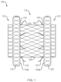
- a medical device 100 of the present disclosure may include an elongate body 110 forming a lumen and comprising a proximal portion, a distal portion, a length and a diameter.
- the elongate body 110 may include an elongate tubular configuration (e.g., constrained, unexpanded or delivery configuration; not shown), and a foreshortened configuration (e.g., unconstrained, expanded or deployed configuration) where the proximal portion 112 radially expands into a proximal retention member 114, and the distal portion 122 radially expands into a distal retention member 124, leaving a cylindrical saddle region 128 extending therebetween.
- a diameter of the cylindrical saddle region 128 may be greater than a diameter of the elongate body 110 in the elongate tubular configuration.
- the proximal and distal retention members 114, 124 may extend perpendicular to a circumference of the elongate body 110 to define respective planar surfaces 114a, 124a.
- the angle of the retention members relative to the circumference of the elongate body may assume other degrees or may change degrees along the retention members creating inflection points in the retention members.
- a plurality of proximal tissue-engaging elements 132 may be disposed along an outer surface of the cylindrical saddle region 128 at a location distal to the proximal retention member 114, and a plurality of distal tissue-engaging elements 142 may be disposed along an outer surface of the cylindrical saddle region 128 at a location proximal to the distal retention member 124.
- a first end 134 of each of the proximal tissue-engaging elements 132 may be attached to the outer surface of the cylindrical saddle region 128, and a second end 136 of each of the proximal tissue-engaging elements 134 may be unattached ( e.g., free) and extend towards the distal retention member 124.
- a first end 144 of each of the distal tissue-engaging elements 142 may be attached to the outer surface of the cylindrical saddle region 128, and a second end 146 of each of the distal tissue-engaging elements 142 may be unattached ( e.g., free) and extend towards the proximal retention member 114.
- the proximal and distal tissue-engaging elements 132, 142 may be disposed along ( e.g., lay flat against) an outer surface of the elongate body. As the elongate body moves to the foreshortened configuration, the proximal and distal tissue-engaging elements 132, 142 may deflect outward to extend along and above the outer surface of the cylindrical saddle region 128 ( e.g., substantially parallel to, or at an acute angle, relative to a longitudinal axis of the cylindrical saddle region).
- first end 134, 144 of any or all of the first and second tissue-engaging elements 132, 142 may be affixed to the outer surface of the cylindrical saddle region 128 using a suitable glue, adhesive, resin or other bonding techniques, as are commonly known in the art.
- the proximal and/or distal tissue-engaging elements 132, 142 may be formed as extensions or projections of the woven, knitted or braided filament comprising the elongate body 110. Any of second ends 136, 146 of the proximal and distal tissue-engaging elements 132, 142 may be sharpened, pointed or otherwise configured to penetrate the tissue wall of a respective first or second body lumen, as discussed below.
- any of the proximal and distal tissue-engaging elements 132, 142 may further include one or more barbs, hooks, fingers and/or teeth, etc. configured to secure the tissue-engaging element(s) within the tissue wall of the respective first or second body lumen.
- proximal and distal tissue-engaging elements 132, 142 of FIG. 1 are depicted as evenly spaced about an outer circumference of the cylindrical saddle region 128 and immediately adjacent to the respective proximal and distal retention members 114, 124, in various embodiments, the proximal and/or distal tissue-engaging elements 132, 142 may include a variety of shapes, sizes, numbers, orientations, patterns and/or spacing along the cylindrical saddle region. In addition, or alternatively, in various embodiments the tissue-engaging elements are not limited to the cylindrical saddle region, but may be positioned on or along the proximal and/or distal retention members, including the planar tissue-facing surfaces.
- a medical device 100 of the present disclosure may be positioned within a patient such that the proximal and distal tissue-engaging elements 132, 142 reorient a portion of the respective first and second body lumens as the medical device moves from the elongate tubular to foreshortened configuration to place the muscularis layers of the first and second body lumens in contact along an outer surface of the cylindrical saddle region 128.
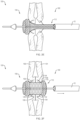
- a medical device 100 of the present disclosure may be disposed in the elongate tubular configuration within the lumen of a tissue-penetrating element 10.
- a sharpened distal end 12 of the tissue-penetrating element 10 may be advanced through the tissue wall 191 of a first body lumen 190 (e.g., the stomach or duodenum) and through the tissue wall 196 of a second body lumen 195 ( e.g., the gallbladder).
- a first body lumen 190 e.g., the stomach or duodenum
- a second body lumen 195 e.g., the gallbladder
- the tissue penetrating element 10 may be advanced over a guidewire 16 previously advanced through the first and second body lumens such that a distal end of the guidewire is disposed within the second body lumen.
- a separate instrument with a sharpened distal tip may be advanced along the path above and into the second body lumen to create a path.
- a guidewire is put in place, or left in place if used to guide the separate instrument, and the separate instrument is withdrawn over the guidewire.
- a medical device according to the various embodiments described above, loaded on a delivery catheter, may be inserted over the guidewire, and the medical device then deployed according to the steps outlined above.
- a distal portion 122 of the medical device 100 may then be advanced distally beyond the lumen of the tissue-penetrating element 10 such that the distal tissue-engaging elements 142 are deployed, e.g., removed from constraint within the lumen of the tissue penetrating element 10.
- the tissue-penetrating element 10 may then be proximally retracted such that at least some of the distal tissue-engaging elements 142 engage ( e.g., pierce or penetrate) a portion of the tissue wall 196 of the second body lumen 195 adjacent to the opening formed by the sharpened distal end 12.
- tissue wall 196 of the second body lumen 195 may be reoriented, e.g., deflected or turned toward the tissue wall 191 of the first body lumen 190.
- the distal portion 122 of the medical device 100 may then be further advanced distally beyond the lumen of the tissue-penetrating element 10 such that the distal retention member 124 is fully deployed within the second body lumen 195 and the planar surface 124a is placed in contact with the inner surface of the tissue wall 196. Still referring to FIG. 2C , as the distal retention member 124 and a portion of the cylindrical saddle region 128 are deployed from within the tissue-penetrating element 10, the portion of the tissue wall 196 of the second body lumen 195 engaged by the distal tissue-engaging elements 142 may be further reoriented to face the tissue wall 191 of the first body lumen 190. Referring to FIGS.
- the tissue-penetrating element 10 may then be further proximally retracted into the first body lumen 190, and a proximal portion 112 of the medical device 100 advanced distally beyond the lumen of the tissue-penetrating element 10 such that the proximal tissue-engaging elements 132 are deployed, e.g., removed from constraint within the lumen of the tissue penetrating element 10, and placed in contact with a portion of the tissue wall 191 of the first body lumen 190 adjacent to the opening formed by the sharpened distal end 12.
- the proximal portion 112 of the medical device 100 may then be further advanced distally beyond the lumen of the tissue-penetrating element 10 such that the proximal retention member 114 is fully deployed within the first body lumen 190 and the planar surface 114a is placed in contact with the inner surface of the tissue wall 191.
- the portion of the tissue wall 191 of the first body lumen 195 engaged by one or more of the proximal tissue-engaging elements 132 may be reoriented to face the previously reoriented tissue wall 196 of the second body lumen 195, thereby placing the respective muscularis layers 194, 199 of the first and second body lumens 190, 195 in contact along the cylindrical saddle region 128.
- the proximal and distal tissue-engaging elements 132, 142 may be sufficiently flexible or deformable to allow the medical device 100 to be removed from the patient without causing substantial trauma to the respective tissue layers.
- any or all of the proximal and distal tissue-engaging elements may be formed from a biodegradable or bioerodible material configured to dissolve after the muscularis layers 194, 199 have fused, thereby allowing the medical device to be more easily removed from the patient.
- a medical device 200 of the present disclosure may be positioned within a patient such that the proximal and distal retention members cause selective and localized tissue necrosis of the first and second body lumens to expose adjacent portions of the muscularis layer of each body lumen along an outer surface of the cylindrical saddle.
- a medical device 200 of the present disclosure may include an elongate body 210 forming a lumen and comprising a proximal portion 212, a distal portion 222, a length and a diameter.
- the elongate body 210 may include an elongate tubular configuration (e.g., constrained, unexpanded or delivery configuration; not shown), and a foreshortened configuration (e.g., unconstrained, expanded or deployed configuration) where the proximal portion 212 radially expands into a proximal retention member 214, and the distal portion 222 radially expands into a distal retention member 224, leaving a cylindrical saddle region 228 extending therebetween.
- a diameter of the cylindrical saddle region 228 may be greater than a diameter of the elongate body 210 in the elongate tubular configuration.
- the proximal and distal retention members 214, 224 may extend perpendicular to a circumference of the elongate body 210 to define respective planar surfaces 214a, 224a.
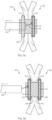
- a first magnet 150 may be disposed within the proximal retention member 214, and a second magnet 152 may be disposed within the distal retention member 224.
- the first and second magnets 150, 152 may be disposed within the respective first and second retention members 214, 224 such that the polarities of each magnet provide an attractive force therebetween about a full circumference ( e.g., 360 degrees) of the cylindrical saddle region 228.
- the medical device 200 may be disposed between first and second body lumens 190, 195 such that the planar surface 214a of the proximal retention member 214 contacts and presses against the tissue wall 191 of the first body lumen 190, and the planar surface 224a of the distal retention member 224 contacts and presses against the tissue wall 196 of the second body lumen 195 to place the body lumens in contact along the cylindrical saddle region 228 ( FIG. 3A ).
- the attractive force between the first and second magnets 150, 152 may urge the proximal and distal retention members 214, 224 toward each other, thereby shortening the cylindrical saddle region 228 and providing constant and consistent pressure between the planar surfaces 214a, 224a and the respective inner surfaces of each tissue wall 191, 196.
- the outer surfaces of each tissue wall may also be compressed against each other between the proximal and distal retention members 214, 224.
- the constant and consistent pressure exerted on the inner and outer surfaces of each tissue wall 191, 196 may cause selective and localized necrosis at a specific depth of each tissue layer.
- the depth of necrosis of the first and second tissue walls 191, 196 may be limited to the mucosal layers 193, 198 to selectively expose and place in contact free ends of the muscularis layers 194, 199 along the cylindrical saddle region 228.
- the medical device 200 may be positioned between the first and second body lumens by following the exemplary steps outlined in FIGS. 2A-2F , as discussed above, with the exception that the tissue walls 191, 196 of the first and second body lumens 190, 195 are placed in contact along the cylindrical saddle region 228, e.g., the respective tissue walls are not reoriented by proximal and distal tissue-engaging elements.
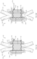
- each of the first and second magnets 150, 152 may include a series of magnet fragments 150a-f, 152a-f loaded onto a delivery wire 154.
- a delivery device 156 (e.g., endoscope, etc.) may be advanced into the second body lumen 195 through the lumen of the medical device 200.
- the delivery wire 154 loaded with a series of magnet fragments 152a-f, may be advanced through the delivery device 156 into the second body lumen 195.
- the delivery device 156 may then be proximally retracted ( FIG.
- FIGS. 4B-4C With the magnetic fragments 152a-f disposed within the distal retention member 224, one end of the delivery wire 154 may be released while the other end is proximally retracted to remove the delivery wire 154 from the medical device 200. This process may be repeated to place magnetic fragments 150a-f within the proximal retention member 214 ( FIG. 4D ).
- each of the first and second magnets 150, 152 may include a flexible magnet configured to move between a restrained (e.g., linear) configuration and an unconstrained (e.g., non-linear or circular) configuration.
- a delivery device 156 e.g., endoscope
- the flexible magnet 152 may be advanced through the delivery device 156 into the second body lumen, such that the magnet 152 moves to the non-constrained configuration ( FIG. 5B ).
- a medical tool 158 e.g., grasper, etc. may be passed through the endoscope to grasp and pull the flexible magnet 152 into the medical device.
- the flexible magnet 152 may deform as it enters the lumen of the medical device and expand ( e.g., snap) into the distal retention member 224 as the medical tool is proximally retracted ( FIG. 5C ). This process may be repeated to place the flexible magnet 150 within the proximal retention member 214 ( FIG. 5D ). With the flexible magnets 150, 152 fully deployed within the proximal and distal retention members 214, 224, selective tissue necrosis of the mucosal layers 193, 198, and fusion of the muscularis layers 194, 199 may proceed as discussed above.
- one or more magnets may be positioned on or adjacent to ( e.g., alongside) the proximal and/or distal retention members to promote selective tissue necrosis of the mucosal layers, and fusion of the muscularis layers.
- magnets may be used in retention members of these devices and other devices to help maintain adjacent tissue layers in apposition for drainage, without the magnets necessarily causing necrosis and fusion.
- a medical device 300 of the present disclosure may include an elongate body forming a lumen and comprising a proximal portion, a distal portion, a length and a diameter.
- the elongate body 310 may include an elongate tubular configuration (e.g., constrained, unexpanded or delivery configuration; not shown), and a foreshortened configuration (e.g., unconstrained, expanded or deployed configuration) where the proximal portion 312 radially expands into a proximal retention member 314, and the distal portion 322 radially expands into a distal retention member 324, leaving a cylindrical saddle region 328 extending therebetween.
- a diameter of the cylindrical saddle region 328 may be greater than a diameter of the elongate body 310 in the elongate tubular configuration.
- the proximal and distal retention members 314, 324 may extend perpendicular to a circumference of the elongate body 310 to define respective planar surfaces 314a, 324a.
- a filament 160 may be threaded through a portion of the elongate body (e.g., through the woven, knitted or braided filament forming the elongate body) such that a first end 162 of the filament 160 is attached to a proximal end of the medical device 300 at a first location (e.g., proximal to the proximal retention member 314), and a second end 164 of the filament 160 is unattached and extends proximally beyond the proximal end of the medical device 300 at a second location different than the first location.
- a first location e.g., proximal to the proximal retention member 314
- first and second locations may be on substantially opposite sides of the medical device ( e.g., separated by 180 degrees).
- a portion of the filament 160 between the first and second ends 162, 164 may form a loop extending along the cylindrical saddle region 328 between the proximal and distal retention members 314, 324.
- the first end 162 of the filament 160 may be affixed to the proximal end of the medical device using a suitable knot, glue, adhesive, resin or other bonding techniques, as are commonly known in the art.
- the filament 160 may be configured to slide through the woven, knitted or braided filament which forms the elongate body such that proximally retracting the second end 164 of the filament 160, while the medical device is immobilized ( e.g., disposed between first and second body lumens) in the foreshortened configuration, may urge the proximal and distal retention members 314, 324 toward each other, thereby shortening the cylindrical saddle region 328.
- a locking member 166 e.g., cleat, tie-off, etc.
- the locking member may be integrally formed from a portion of the filament which forms the elongate body 310.
- the locking member 166 may be configured to securingly receive/engage a portion of the filament 160 (e.g., loops, windings, etc.) after the second end 164 of the filament 160 has been proximally retracted, thereby maintaining the proximal and distal retention members 314, 324 in the compressed ( e.g., further foreshortened) configuration.
- a portion of the filament 160 e.g., loops, windings, etc.
- the filament 160 may be proximally retracted and "tied-off to the locking member 166 to establish the desired amount of pressure to the tissue walls 191, 196 of the first and second body lumens 190, 195, as discussed below.
- a distance between the proximal and distal retention members 314, 324 (and pressure applied to the respective tissue walls) may be adjusted as necessary by securing different portions of the filament 160 to the locking member 166. For example, additional force may be applied between the respective tissue walls by releasing ( e.g., untying) the filament 160 from the locking member 166, further proximally retracting the second end 164 and re-securing the filament 160 to the locking member 166.
- the force applied between the respective tissue walls may be decreased by releasing the filament 160 from the locking member 166, allowing the second end 164 to slide distally and re-securing the filament 160 to the locking member 166.
- the filament 160 may be released from the locking member 166 and the free end 164 allowed to slide distally without being re-secured to the locking member 166 as a first step in removing the medical device 300 from the patient.
- the medical device 300 may be positioned between the first and second body lumens by following the exemplary steps outlined in FIGS. 2A-2F , as discussed above, with the exception that the tissue walls 191, 196 of the first and second body lumens 190, 195 are placed in contact along the cylindrical saddle region 328, e.g., the respective tissue walls are not reoriented by proximal and distal tissue-engaging elements.
- the planar surface 314a of the proximal retention member 314 may contact and press against the tissue wall 191 of the first body lumen 190, and the planar surface 324a of the distal retention member 324 may contact and press against the tissue wall 196 of the second body lumen 195 to place the body lumens in contact along the cylindrical saddle region 328 ( FIG. 6A ).
- the second end 164 of the filament 160 may then be proximally retracted ( e.g., using a suitable grasping member, etc.) to urge the proximal and distal retention members 314, 324 toward each other and secured to the locking member 166, thereby providing constant and consistent pressure between the planar surfaces 314a, 324a and the respective inner surfaces of each tissue wall 191, 196.
- the outer surfaces of each tissue wall may also be compressed against each other between the proximal and distal retention members 314, 324.
- the constant and consistent pressure exerted on the inner and outer surfaces of each tissue wall 191, 196 may cause selective and localized necrosis at a specific depth of each tissue layer.
- the depth of necrosis of the first and second tissue walls 191, 196 may be limited to the mucosal layers 193, 198 to selectively expose and place in contact free ends of the muscularis layers 194, 199 along the cylindrical saddle region 328 ( FIG. 6B ).
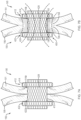
- a medical device 400 of the present disclosure may establish a long term or permanent open flow or access passage without reorienting (e.g., FIGS. 1-2F ) or compressing ( e.g., FIGS. 3A-6B ) the tissue walls 191, 196 of the first and second body lumens 190, 195 along the cylindrical saddle region.
- a medical device 400 of the present disclosure may include an elongate body forming a lumen and comprising a proximal portion, a distal portion, a length and a diameter.
- the elongate body 410 may include an elongate tubular configuration (e.g., constrained, unexpanded or delivery configuration; not shown), and a foreshortened configuration (e.g., unconstrained, expanded or deployed configuration) where the proximal portion 412 radially expands into a proximal retention member 414, and the distal portion 422 radially expands into a distal retention member 424, leaving a cylindrical saddle region 428 extending therebetween.
- a diameter of the cylindrical saddle region 428 may be greater than a diameter of the elongate body 410 in the elongate tubular configuration.
- the proximal and distal retention members 414, 424 may extend perpendicular to a circumference of the elongate body 410 to define respective planar surfaces 414a, 424a.
- the medical device 400 may be positioned between the first and second body lumens by following the exemplary steps outlined in FIGS. 2A-2F , as discussed above, with the exception that the tissue walls 191, 196 of the first and second body lumens 190, 195 are placed in contact along the cylindrical saddle region 428, e.g., the respective tissue walls are not reoriented by proximal and distal tissue-engaging elements.
- the planar surface 414a of the proximal retention member 414 my contact and press against the tissue wall 191 of the first body lumen 190, and the planar surface 424a of the distal retention member 424 may contact and press against the tissue wall 196 of the second body lumen 195, to place the body lumens in contact along the cylindrical saddle region 428 ( FIG. 7A ).
- the medical device 400 may include an amount of ferrous material (e.g., formed within the membrane or coating and/or the woven, knitted or braided filament of the elongate body) such that exposure of the patient to an appropriate magnetic field may cause localized vibration of the medical device 400.
- Establishing the proper frequency of vibrations within the medical device e.g., by exposing the medical device to the magnetic field generated by a standard MRI machine, may cause the medical device to heat to an appropriate temperature to selectively kill the cells of the mucosal layer 194, 198 of the first and second body lumens 190, 195.
- heat emitted from the medical device 400 may also cauterize the exposed tissue surfaces to facilitate fusion of the muscularis layers ( FIG. 7B ).
- radiofrequency induced heating of an implanted medical device may cause cell death when the surrounding tissues are exposed to an elevated temperature (e.g., above 37 °C; body temperature) for an extended period of time.
- cell death may occur after one minute of exposure of a medical device heated to 45.7 °C ( e.g., 8.7 °C above body temperature), or after 160 minutes of exposure to a medical device heated to 42.0 °C ( e.g., 5.0 °C over body temperature).
- any or all of the medical devices 100, 200, 300 disclosed herein may also include an MRI-induced heating step to further promote the requisite killing of the cells comprising the mucosal layers and place the adjacent muscularis layers of the first and second body lumens in contact.
- any of the medical device 100, 200, 300, 400 disclosed herein may include any combination of the elements (e.g., tissue-engaging elements, magnets or slidable filaments, ferrous materials, etc.) disclosed herein.
- the elongate body of any of the medical devices 100, 200, 300, 400 depicted in FIGS. 1-7B may be formed of a woven, knitted or braided filament (e.g., nitinol wire, etc.).
- the proximal retention member, distal retention member and/or cylindrical saddle region may further include a membrane or coating on an inner and/or outer surface thereof to define a contiguous open interior passage configured for flow (e.g., body fluids, materials, and the like) and/or access therethrough.
- the coating may comprise a variety of non-degradable and biocompatible polymeric materials (e.g., upon exposure to bodily fluids such as bile), including, for example, silicones, rubbers, polyethylenes, PVDF, Chronoflex ® and thermoplastic elastomers such that the coating conforms to the medical device in the elongate tubular and foreshortened configurations.
- the woven, knitted or braided filament in any of the various embodiments may be metal filament or polymer filament, and may further include a single filament woven upon itself or multiple filaments woven together.
- the open interior passage may further include one or more valves (e.g., duck-bill valve, slit valve, etc.) moveable between closed and open configurations to block or prevent the flow of fluids therethrough, until the patient or medical professional determines that the valve should be opened ( e.g., by inserting a drainage tube).
- valves e.g., duck-bill valve, slit valve, etc.
- These valves may be positioned anywhere along the open interior passage of the elongate body. Examples of such valves are described in U.S. Patent Publication No. 2012/0226243 , the contents of which is hereby incorporated by reference in its entirety.
- Such valves may comprise a variety of suitable biocompatible and non-degradable materials, including any of the polymers discussed herein, and may be utilized with any of the various embodiments described or otherwise contemplated as within the scope of the present disclosure.
- the first and second retention members of any of the medical devices 100, 200, 300, 400 depicted in FIGS. 1-7B may include various configurations, such that one or more of the retention members extend radially at an angle that is not necessarily perpendicular to the elongate body and/or the surfaces are not necessarily planar.
- one or both of the proximal and distal retention members may extend outward towards an end of the elongate body, back towards a center portion of the elongate body, or change directions in some combination of both.
- one or both of the proximal and distal retention members may include an outer diameter d 1 that is greater than an outer diameter d 2 of the cylindrical saddle region.
- outer diameter d 1 may be as much as 75%-100% greater than an outer diameter d 2 of the cylindrical saddle region.
- outer diameter d 1 may be approximately 7.0 mm to approximately 30 mm
- outer diameter d 2 may be approximately 3.0 mm to approximately 15.0 mm.
- the size (e.g., diameter) of the opening formed between the first and second body lumens may be increased or decreased by increasing or decreasing the size (e.g., width) of the proximal and distal retention members (e.g., increasing or decreasing the surface area of the tissue layers compressed between the proximal and distal retention members).
- a length of the elongate body in the foreshortened configuration may be at least 40% shorter than a length of the elongate body when in the elongate tubular configuration.
- any of the medical devices 100, 200, 300, 400 of the present disclosure may remain in place within the patient for a sufficient amount of time for the muscularis layers 194, 195 to join or fuse ( e.g., grow together), at which point the medical device may be removed from the patient to leave a long term or permanent open flow, drainage or access passage between the first and second body lumens 190, 195.
- the medical devices 100, 200, 300, 400 may be maintained within the body for a period of days to weeks to establish the requisite level of tissue necrosis between the proximal and distal retention members. The necrotic tissue may eventually slough off to leave a permanent opening defined by the fused muscularis layers.
- any of the medical devices 100, 200, 300, 400 of the present disclosure may further include one or more chemicals (e.g., silver nitrate) or anti-proliferative agents embedded on or within the coating of the medical device, including, for example, the cylindrical saddle region and/or the planar surfaces of the proximal and distal retention members, to further facilitate selective killing of the cells of the mucosal layer of the first and second body lumens.
- a surgical glue, cryocautery or cryoablation treatment may be applied to the inside diameter of the opening between the first and second body lumens to seal the fused muscularis layers and further prevent the ingrowth of mucosal cells.
- an opening established between first and second body lumens as described herein may be maintained by replacing the medical device used to establish the opening with a permanent implant (e.g., grommet) configured to physically prevent (e.g., block) the opening from closing or re-sealing.
- a medical device 500 of the present disclosure may include interlockable first and second flexible members 172, 182.
- first and second flexible members 172, 182 may be formed from a suitable polymeric material (e.g., silicones, rubbers and the like) configured to be deformed, bent, fold, rolled, compressed or otherwise deformed ( e.g., within a delivery sheath, etc.) for delivery into a first or second body lumen, and return to the original non-deformed configuration once released from constraint within the respective body lumen.
- a suitable polymeric material e.g., silicones, rubbers and the like
- the first flexible member 172 may include an outer surface 174, a substantially flat or planer inner surface 176, an outer edge 175 with a first circumference and an inner edge 177 with a second circumference less than the first circumference, wherein the inner edge 177 defines a first opening 178 extending between the outer and inner surfaces 174, 176.
- a plurality of recesses 189a, 189b ( e.g., two or more) may be formed within the inner surface 176 along the outer edge 175 of the first flexible member 172.
- the second flexible member 182 may include an outer surface 184, a substantially flat or planer inner surface 186, an outer edge 185 with a first circumference and an inner edge 187 with a second circumference less than the first circumference, wherein the inner edge 187 defines a second opening 188 extending between the outer and inner surfaces 184, 186.
- a plurality of tabs 199a, 199b (e.g., two or more) may extend from the inner surface 186 along the outer edge 185 of the second flexible member 182.
- a cylinder 181 coextensive with the second opening 188 may also extend from the inner surface 186 of the second flexible member 182.
- Each recess 189a, 189b of the first flexible member 172 may be configured to securingly receive a corresponding tab 199a, 199b of the second flexible member 182, e.g., in an interlocking or snap-fit manner, such that the first and second openings 178, 188 align to form a contiguous open lumen defined by the cylinder 181, and with the inner surfaces 176, 186 of the first and second flexible members 172, 182 separated by a predetermined distance.
- a medical device 500 of the present disclosure may be disposed within a previously formed opening between first and second body lumens 190, 195 by loading the first and second flexible members 172, 182 within the lumen of a delivery tube in a folded or compressed configuration (not shown).
- the delivery tube may be advanced through the opening between the first and second body lumens 190, 195 such that a distal end of the delivery tube is disposed within the second body lumen 195.
- the second flexible member 182 may then be advanced distally beyond the lumen of the delivery tube such that the second flexible member 182 moves to a non-constrained configuration within the second body lumen 195.
- a separate medical device may be advanced through the lumen of the delivery tube, or along an outer surface of the delivery tube, to grasp the second flexible member 182 and place the plurality of tabs 199a, 199b in contact with the tissue wall 196 of the second body lumen 196 such that the second opening 188 aligns with the opening between the first and second body lumens 190, 195.
- the medical device may then be proximally retracted with sufficient force that the tabs 199a, 199b of the second flexible member 182 penetrate and extend through the tissue walls 191, 196 of the first and second body lumens 190, 195, and the cylinder 181 extends through the opening between the first and second body lumens 190, 195.
- the delivery tube may then be proximally retracted such that the distal end of the delivery tube is disposed within the first body lumen 190.
- the first flexible member 172 may then be advanced distally beyond the lumen of the delivery tube such that the first flexible member 172 moves to a non-constrained configuration with the first body lumen 190.
- the first flexible member 172 may be placed in contact with the tissue wall 191 of the first body lumen 190 such that the first opening 178 aligns with the opening between the first and second body lumens 190, 195, the recesses 189a, 189b on the inner surface 174 of the first flexible member 172 align with the tabs 199a, 199b of the second flexible member 182 extending into the first body lumen 190 and the cylinder 181 extends through the opening between the first and second body lumens 190, 195.
- the distal end of the delivery tube may be used to place the first flexible member 172 in contact with the tissue wall 191 of the first body lumen 190.
- a second medical device may be positioned within the first body lumen 190 to grasp the first flexible member 172 and align the recesses 189a, 189b with the respective ends of the tabs 199a, 199b.
- the first and second flexible members 172, 182 may then be advanced toward each other such that the tabs 199a, 199b extending from the inner surface 186 of the second flexible member 182 engage the corresponding recesses 189a, 189b on the inner surface 176 of the second flexible member 172, thereby aligning the first and second openings 178, 188 of the first and second flexible members 172, 176 with the opening between the first and second body lumens.
- a predetermined distance between the inner surfaces 176, 186 of the first and second flexible members 172, 182 may allow the tissue walls 191, 196 of the first and second body lumens to be maintained in a non-compressed state (e.g., one that does not induce tissue necrosis) throughout the duration of the medical device being implanted within the patient.
- FIGS. 9A-9B depicts two tabs 199a, 199b and two corresponding recesses 189a, 189b disposed on opposite sides of the ends of their respective flexible members 172, 182, in various embodiments, any number or tabs and recesses may be disposed in a variety of patterns, orientations and/or configurations.
- a medical device 500 of the present disclosure may include interlockable first and second flexible members 172, 182, as discussed above.
- a cylinder 181 coextensive with the second opening 188 may extend from the inner surface 186 of the second flexible member 182.
- a free end of the cylinder may include series of tabs (or a single continuous or circular tab) configured to extend through an opening between the first and second body lumens and engage a corresponding recess 173 ( e.g., circular groove) surrounding the first opening 178 of the first flexible member 172 in an interlocking or snap-fit manner, such that the first and second openings 178, 188 align to form a contiguous open lumen defined by the cylinder 181, and with the inner surfaces 176, 186 of the first and second flexible members 172, 182 separated by a predetermined distance.
- series of tabs or a single continuous or circular tab
- first and second flexible members 172, 182 are not limited to being disposed within the first and second body lumens.
- the first flexible member may be disposed within the second body lumen to receive the tabs of the second flexible member positioned within the first body lumen.
Landscapes
- Health & Medical Sciences (AREA)
- Engineering & Computer Science (AREA)
- Biomedical Technology (AREA)
- Life Sciences & Earth Sciences (AREA)
- Heart & Thoracic Surgery (AREA)
- Animal Behavior & Ethology (AREA)
- General Health & Medical Sciences (AREA)
- Public Health (AREA)
- Veterinary Medicine (AREA)
- Vascular Medicine (AREA)
- Cardiology (AREA)
- Transplantation (AREA)
- Oral & Maxillofacial Surgery (AREA)
- Surgery (AREA)
- Hematology (AREA)
- Anesthesiology (AREA)
- Molecular Biology (AREA)
- Nuclear Medicine, Radiotherapy & Molecular Imaging (AREA)
- Medical Informatics (AREA)
- Pulmonology (AREA)
- Gastroenterology & Hepatology (AREA)
- Otolaryngology (AREA)
- Ophthalmology & Optometry (AREA)
- Physiology (AREA)
- Surgical Instruments (AREA)
- Pathology (AREA)
- External Artificial Organs (AREA)
- Media Introduction/Drainage Providing Device (AREA)
- Prostheses (AREA)
- Physics & Mathematics (AREA)
- Plasma & Fusion (AREA)
Abstract
Description
- The present application claims the benefit of priority under 35 U.S.C. § 119 to
U.S. Provisional Application Serial No. 62/522,348, filed on June 20, 2017 - The present disclosure relates generally to the field of medical devices and establishing fluid communication between body lumens. In particular, the present disclosure relates to devices and methods for establishing a permanent open flow or access passage between body lumens.
- The desire to establish access to body lumens to create fluid communication from one to the other is present under various circumstances and conditions. A variety of medical devices (e.g., drainage stents, etc.) are able to establish open flow or access passages between body lumens. These medical devices are generally not indicated for long-term use, and are often removed from the patient within weeks or months after placement. Once the medical device has been removed, the rapidly replenishing cells of the mucosal layer of each body lumen may inherently close or seal the opening (e.g., fistula, anastomosis, etc.). While this self-sealing ability may be advantageous in certain circumstances, various medical conditions require a long term or permanent opening to be maintained between the body lumens after the anastomotic device has been removed from the patient.
- For example, blockage of bile flow from the gallbladder to the common bile duct (CBD) causes accumulation of bile within the gallbladder, leading to jaundice in the short term and potentially life-threatening consequences in the long term. Commercially available drainage devices (e.g., Axios™ Stent, Boston Scientific Corporation) may be placed to provide relief from acute cholecystitis by draining bile and/or gallstones from the gallbladder to the duodenum. Since these drainage devices are not indicated for permanent implantation, the standard of care for treating chronic cholecystitis is gallbladder removal. Approximately 800,000 gallbladder removal procedures are performed each year in the U.S alone.
- A variety of advantageous medical outcomes may be realized by the devices and/or methods of the present disclosure, for example, placing the tissue walls of first and second body lumens in direct contact such that the apposed muscularis layers fuse together to form a long term or permanent open flow or access passage that prevents or significantly inhibits closure or sealing.
- In one aspect, the present disclosure relates to a medical device comprising an elongate body forming a lumen and including a proximal portion, a distal portion, a length and a diameter. The elongate body may include an elongate tubular configuration, and a foreshortened configuration where the proximal portion may expand into a proximal retention member and the distal portion may expand into a distal retention member leaving a cylindrical saddle region therebetween. A plurality of proximal tissue-engaging elements may be disposed along an outer surface of the cylindrical saddle region distal to the proximal retention member, and a plurality of distal tissue-engaging elements may be disposed along an outer surface of the cylindrical saddle region proximal to the distal retention member. A first end of each proximal tissue-engaging element may be attached to the outer surface of the cylindrical saddle region, and a second end of each proximal tissue-engaging element may be unattached and extend toward the distal retention member. A first end of each distal tissue-engaging element may be attached to the outer surface of the cylindrical saddle region, and a second end of each distal tissue-engaging element may be unattached and extend toward the proximal retention member. The unattached second end of each proximal tissue-engaging element may be elevated about the outer surface of the cylindrical saddle region. The unattached second end of each distal tissue-engaging element may be elevated about the outer surface of the cylindrical saddle region. The unattached second end of each proximal tissue-engaging element may be configured to penetrate a tissue wall of a first body lumen. The unattached second end of each distal tissue-engaging element may be configured to penetrate a tissue wall of a second body lumen. The plurality of proximal and/or distal tissue-engaging elements may lay flat against the outer surface of the elongate body when in the elongate tubular configuration. A surface of the proximal retention member may be configured to contact an inner surface of a tissue wall of a first body lumen, and a surface of the distal retention member may be configured to contact an inner surface of a tissue wall of a second body lumen. The tissue walls of the first and second body lumens may be apposed between the proximal and distal retention members along the cylindrical saddle region. A portion of the tissue wall of the first body lumen engaged by the plurality of proximal tissue-engaging elements may deflect along the cylindrical saddle region toward the distal retention member, and a portion of the tissue wall of the second body lumen engaged by the plurality of distal tissue-engaging elements may deflect along the cylindrical saddle region toward the proximal retention member, thereby placing a tissue layer (e.g., muscularis layer) of the tissue wall of the first body lumen in contact with a tissue layer (e.g., muscularis layer) of the tissue wall of the second body lumen.
- In another aspect, the present disclosure relates to a medical device comprising an elongate body forming a lumen and comprising a proximal portion, a distal portion, a length and a diameter. The elongate body may include an elongate tubular configuration, and a foreshortened configuration where the proximal portion may expand into a proximal retention member and the distal portion may expand into a distal retention member leaving a cylindrical saddle region therebetween. A first magnet may be disposed within proximal retention member, and a second magnet may be disposed within the distal retention member. An attractive force between the first and second magnets may urge the proximal and distal retention members toward each other. A surface of the proximal retention member may be configured to contact an inner surface of a tissue wall of a first body lumen, and a surface of the distal retention member may be configured to contact an inner surface of a tissue wall of a second body lumen. The tissue walls of the first and second body lumens may be apposed between the proximal and distal retention members along the cylindrical saddle region. The surface of the proximal retention member may cause necrosis within the tissue wall of the first body lumen, and the surface of the distal retention member may cause necrosis within the tissue wall of the second body lumen. The necrosis within the tissue walls of the first and second body lumens may expose and place a healthy tissue layer (e.g., muscularis layer) of the first and second body lumens in contact with each other.
- In another aspect, the present disclosure relates to a medical device comprising an elongate body forming a lumen and comprising a proximal portion, a distal portion, a length and a diameter. The elongate body may include an elongate tubular configuration, and a foreshortened configuration where the proximal portion may expand into a proximal retention member and the distal portion may expand into a distal retention member leaving a cylindrical saddle region therebetween. A filament may be threaded through a portion of the elongate body to effectuate compression of the proximal and distal ends toward each other. For example, a first end of the filament may be attached to a proximal end of the medical device at a first location, a second end of the filament may be unattached and extend from the proximal end of the medical device at a second location, and a portion of the filament between the first and second ends may form a loop extending along the cylindrical saddle region between the proximal and distal retention members. Proximally retracting the second end of the filament may urge the proximal and distal retention members toward each other. The medical device may further include a locking member attached to the elongate body adjacent to the second location. The locking member may be configured to secure a portion of the filament. A surface of the proximal retention member may be configured to contact an inner surface of a tissue wall of a first body lumen, and a surface of the distal retention member may be configured to contact an inner surface of a tissue wall of a second body lumen. The tissue walls of the first and second body lumens may be apposed between the proximal and distal retention members along the cylindrical saddle region. The surface of the proximal retention member may cause necrosis within the tissue wall of the first body lumen, and the surface of the distal retention member may cause necrosis within the tissue wall of the second body lumen. The necrosis within the tissue walls of the first and second body lumens may expose and place a healthy tissue layer (e.g., muscularis layer) of the first and second body lumens in contact with each other.
- In another aspect, the present disclosure relates to a medical device comprising an elongate body forming a lumen and comprising a proximal portion, a distal portion, a length and a diameter. The elongate body may include an elongate tubular configuration, and a foreshortened configuration where the proximal portion may expand into a proximal retention member and the distal portion may expand into a distal retention member leaving a cylindrical saddle region therebetween. The medical device may become heated in the presence of energy, including MRI energy, and cause necrosis within the tissue walls of the first and second body lumens. The necrosis within the tissue walls of the first and second body lumens may expose and place a healthy tissue layer (e.g., muscularis layer) of the first and second body lumens in contact with each other.
- In another aspect, the present disclosure relates to a medical device comprising a first flexible member which includes an inner surface, an outer surface and a first opening extending therebetween, and second flexible member comprising an inner surface, an outer surface and a second opening therebetween. A plurality of tabs may extend from the inner surface of the second flexible member, and a plurality of recesses may be formed within the inner surface of the first flexible member. Each recess of the first flexible member may be configured to receive a corresponding tab of the second flexible member such that the first and second openings may align to form a combined opening. The inner surface of the first flexible member and the inner surface of the second flexible member may be separated by a distance when the plurality of tabs may be received within the plurality of recesses. The plurality of tabs may be configured to penetrate the tissue walls of a first and second body lumen. The plurality of tabs may be configured to extend through an opening between the tissue walls a first and second body lumen.
- Non-limiting embodiments of the present disclosure are described by way of example with reference to the accompanying figures, which are schematic and not intended to be drawn to scale. In the figures, each identical or nearly identical component illustrated is typically represented by a single numeral. For purposes of clarity, not every component is labeled in every figure, nor is every component of each embodiment shown where illustration is not necessary to allow those of ordinary skill in the art to understand the disclosure. In the figures:
-
FIG. 1 provides a perspective view of a medical device, according to one embodiment of the present disclosure. -
FIGS. 2A-2F illustrate exemplary steps for placement of a medical device between first and second body lumens, according to one embodiment of the present disclosure. -
FIGS. 3A-3B provide a perspective view of a medical device disposed between first and second body lumens, according to one embodiment of the present disclosure. -
FIGS. 4A-4D illustrate exemplary steps for the placement of magnets within the proximal and distal retention members of a medical device, according to one embodiment of the present disclosure. -
FIGS. 5A-5D illustrate exemplary steps for the placement of magnets within the proximal and distal retention members of a medical device, according to one embodiment of the present disclosure. -
FIGS. 6A-6B provide perspective views of a medical device disposed between first and second body lumens, according to one embodiment of the present disclosure. -
FIGS. 7A-7B provide perspective views of a medical device disposed between first and second body lumens, according to one embodiment of the present disclosure. -
FIG. 8 provides calculations and equations for radiofrequency induced heating of an implanted medical, according to one embodiment of the present disclosure. -
FIGS. 9A-9C provide perspective views of a medical device disposed between first and second body lumens, according to one embodiment of the present disclosure. - The present disclosure is not limited to the particular embodiments described. The terminology used herein is for the purpose of describing particular embodiments only, and is not intended to be limiting beyond the scope of the appended claims. Unless otherwise defined, all technical terms used herein have the same meaning as commonly understood by one of ordinary skill in the art to which the disclosure belongs.
- Although embodiments of the present disclosure are described with specific reference to medical devices (e.g., stents, etc.) and systems for drainage of the gallbladder, it should be appreciated that such medical devices may be used in a variety of medical procedures (e.g., external biliary drain conversion, enteroenterostomy, gastrojejumostomy, gastroduodenostomy and gastroileostomy, etc.) to establish and/or maintain a temporary or permanent open flow or drainage passage from or between a variety of body organs, lumens, ducts, vessels, fistulas, cysts and spaces (e.g., the dermis, stomach, duodenum, jejunum, small intestine, gallbladder, kidneys, pancreas, biliary / pancreatic trees, bladder, ureter, abscesses, walled-off pancreatic necrosis (WOPN), bile ducts, etc.). The devices can be inserted via different access points and approaches, e.g., percutaneously, endoscopically, laparoscopically or some combination thereof. The medical devices disclosed herein are self-expanding, but in other embodiments the medical device may be expandable by other means, including, e.g., a balloon catheter. Moreover, such medical devices are not limited to drainage, but may facilitate access to organs, vessels or body lumens for other purposes, such as creating a path to divert or bypass fluids or solids from one location to another, removing obstructions and/or delivering therapy, including non-invasive or minimally invasive manipulation of the tissue within the organ and/or the introduction of pharmacological agents via the open flow passage.
- As used herein, the singular forms "a," "an," and "the" are intended to include the plural forms as well, unless the context clearly indicates otherwise. It will be further understood that the terms "comprises" and/or "comprising," or "includes" and/or "including" when used herein, specify the presence of stated features, regions, steps, elements and/or components, but do not preclude the presence or addition of one or more other features, regions, integers, steps, operations, elements, components and/or groups thereof.
- As used herein, the term "distal" refers to the end farthest away from the medical professional when introducing a device into a patient, while the term "proximal" refers to the end closest to the medical professional when introducing a device into a patient.
- In one embodiment, the present disclosure relates to a medical device (e.g., self-expanding drainage stent, etc.) configured to extend between first and second body lumens and align the respective muscularis layers of each body lumen to establish a long term or permanent open flow or access passage therebetween. Referring to
FIG. 1 , in one embodiment, amedical device 100 of the present disclosure may include anelongate body 110 forming a lumen and comprising a proximal portion, a distal portion, a length and a diameter. Theelongate body 110 may include an elongate tubular configuration (e.g., constrained, unexpanded or delivery configuration; not shown), and a foreshortened configuration (e.g., unconstrained, expanded or deployed configuration) where theproximal portion 112 radially expands into aproximal retention member 114, and thedistal portion 122 radially expands into adistal retention member 124, leaving acylindrical saddle region 128 extending therebetween. A diameter of thecylindrical saddle region 128 may be greater than a diameter of theelongate body 110 in the elongate tubular configuration. The proximal anddistal retention members elongate body 110 to define respectiveplanar surfaces elements 132 may be disposed along an outer surface of thecylindrical saddle region 128 at a location distal to theproximal retention member 114, and a plurality of distal tissue-engagingelements 142 may be disposed along an outer surface of thecylindrical saddle region 128 at a location proximal to thedistal retention member 124. Afirst end 134 of each of the proximal tissue-engagingelements 132 may be attached to the outer surface of thecylindrical saddle region 128, and asecond end 136 of each of the proximal tissue-engagingelements 134 may be unattached (e.g., free) and extend towards thedistal retention member 124. Afirst end 144 of each of the distal tissue-engagingelements 142 may be attached to the outer surface of thecylindrical saddle region 128, and asecond end 146 of each of the distal tissue-engagingelements 142 may be unattached (e.g., free) and extend towards theproximal retention member 114. In the elongate tubular configuration, the proximal and distal tissue-engagingelements elements - In various embodiments, the
first end elements cylindrical saddle region 128 using a suitable glue, adhesive, resin or other bonding techniques, as are commonly known in the art. In addition, or alternatively, the proximal and/or distal tissue-engagingelements elongate body 110. Any of second ends 136, 146 of the proximal and distal tissue-engagingelements elements - Although the proximal and distal tissue-engaging
elements FIG. 1 are depicted as evenly spaced about an outer circumference of thecylindrical saddle region 128 and immediately adjacent to the respective proximal anddistal retention members elements - In one embodiment, a
medical device 100 of the present disclosure may be positioned within a patient such that the proximal and distal tissue-engagingelements cylindrical saddle region 128. Referring toFIGS. 2A-2F , in use and by way of example, amedical device 100 of the present disclosure may be disposed in the elongate tubular configuration within the lumen of a tissue-penetratingelement 10. A sharpeneddistal end 12 of the tissue-penetratingelement 10 may be advanced through thetissue wall 191 of a first body lumen 190 (e.g., the stomach or duodenum) and through thetissue wall 196 of a second body lumen 195 (e.g., the gallbladder). - In various embodiments, the
tissue penetrating element 10 may be advanced over aguidewire 16 previously advanced through the first and second body lumens such that a distal end of the guidewire is disposed within the second body lumen. Alternatively, in the method above, a separate instrument with a sharpened distal tip may be advanced along the path above and into the second body lumen to create a path. A guidewire is put in place, or left in place if used to guide the separate instrument, and the separate instrument is withdrawn over the guidewire. A medical device, according to the various embodiments described above, loaded on a delivery catheter, may be inserted over the guidewire, and the medical device then deployed according to the steps outlined above. - Referring to
FIG. 2A , adistal portion 122 of themedical device 100 may then be advanced distally beyond the lumen of the tissue-penetratingelement 10 such that the distal tissue-engagingelements 142 are deployed, e.g., removed from constraint within the lumen of thetissue penetrating element 10. Referring toFIG. 2B , the tissue-penetratingelement 10 may then be proximally retracted such that at least some of the distal tissue-engagingelements 142 engage (e.g., pierce or penetrate) a portion of thetissue wall 196 of thesecond body lumen 195 adjacent to the opening formed by the sharpeneddistal end 12. As the tissue-penetratingelement 10 is further proximally retracted, a portion of thetissue wall 196 of thesecond body lumen 195 may be reoriented, e.g., deflected or turned toward thetissue wall 191 of thefirst body lumen 190. - Referring to
FIG. 2C , thedistal portion 122 of themedical device 100 may then be further advanced distally beyond the lumen of the tissue-penetratingelement 10 such that thedistal retention member 124 is fully deployed within thesecond body lumen 195 and theplanar surface 124a is placed in contact with the inner surface of thetissue wall 196. Still referring toFIG. 2C , as thedistal retention member 124 and a portion of thecylindrical saddle region 128 are deployed from within the tissue-penetratingelement 10, the portion of thetissue wall 196 of thesecond body lumen 195 engaged by the distal tissue-engagingelements 142 may be further reoriented to face thetissue wall 191 of thefirst body lumen 190. Referring toFIGS. 2D and2E , the tissue-penetratingelement 10 may then be further proximally retracted into thefirst body lumen 190, and aproximal portion 112 of themedical device 100 advanced distally beyond the lumen of the tissue-penetratingelement 10 such that the proximal tissue-engagingelements 132 are deployed, e.g., removed from constraint within the lumen of thetissue penetrating element 10, and placed in contact with a portion of thetissue wall 191 of thefirst body lumen 190 adjacent to the opening formed by the sharpeneddistal end 12. Referring toFIG. 2F , theproximal portion 112 of themedical device 100 may then be further advanced distally beyond the lumen of the tissue-penetratingelement 10 such that theproximal retention member 114 is fully deployed within thefirst body lumen 190 and theplanar surface 114a is placed in contact with the inner surface of thetissue wall 191. In one embodiment, as theproximal retention member 114 and remaining portion of thecylindrical saddle region 128 are deployed from within the tissue-penetratingelement 10, the portion of thetissue wall 191 of thefirst body lumen 195 engaged by one or more of the proximal tissue-engagingelements 132 may be reoriented to face the previously reorientedtissue wall 196 of thesecond body lumen 195, thereby placing the respective muscularis layers 194, 199 of the first andsecond body lumens cylindrical saddle region 128. - In various embodiments, the proximal and distal tissue-engaging
elements medical device 100 to be removed from the patient without causing substantial trauma to the respective tissue layers. In addition, or alternatively, any or all of the proximal and distal tissue-engaging elements may be formed from a biodegradable or bioerodible material configured to dissolve after the muscularis layers 194, 199 have fused, thereby allowing the medical device to be more easily removed from the patient. - In one embodiment, a
medical device 200 of the present disclosure may be positioned within a patient such that the proximal and distal retention members cause selective and localized tissue necrosis of the first and second body lumens to expose adjacent portions of the muscularis layer of each body lumen along an outer surface of the cylindrical saddle. Referring toFIGS. 3A-3B , in one embodiment, amedical device 200 of the present disclosure may include anelongate body 210 forming a lumen and comprising aproximal portion 212, adistal portion 222, a length and a diameter. Theelongate body 210 may include an elongate tubular configuration (e.g., constrained, unexpanded or delivery configuration; not shown), and a foreshortened configuration (e.g., unconstrained, expanded or deployed configuration) where theproximal portion 212 radially expands into aproximal retention member 214, and thedistal portion 222 radially expands into adistal retention member 224, leaving acylindrical saddle region 228 extending therebetween. A diameter of thecylindrical saddle region 228 may be greater than a diameter of theelongate body 210 in the elongate tubular configuration. The proximal anddistal retention members elongate body 210 to define respectiveplanar surfaces 214a, 224a. Afirst magnet 150 may be disposed within theproximal retention member 214, and asecond magnet 152 may be disposed within thedistal retention member 224. The first andsecond magnets second retention members cylindrical saddle region 228. As discussed in greater detail below, themedical device 200 may be disposed between first andsecond body lumens planar surface 214a of theproximal retention member 214 contacts and presses against thetissue wall 191 of thefirst body lumen 190, and the planar surface 224a of thedistal retention member 224 contacts and presses against thetissue wall 196 of thesecond body lumen 195 to place the body lumens in contact along the cylindrical saddle region 228 (FIG. 3A ). In one embodiment, the attractive force between the first andsecond magnets distal retention members cylindrical saddle region 228 and providing constant and consistent pressure between theplanar surfaces 214a, 224a and the respective inner surfaces of eachtissue wall distal retention members tissue wall second tissue walls mucosal layers cylindrical saddle region 228. - In one embodiment, the
medical device 200 may be positioned between the first and second body lumens by following the exemplary steps outlined inFIGS. 2A-2F , as discussed above, with the exception that thetissue walls second body lumens cylindrical saddle region 228, e.g., the respective tissue walls are not reoriented by proximal and distal tissue-engaging elements. Referring toFIGS. 4A-4D , in one embodiment, each of the first andsecond magnets delivery wire 154. With themedical device 200 properly positioned between the first andsecond body lumens second body lumen 195 through the lumen of themedical device 200. Thedelivery wire 154, loaded with a series ofmagnet fragments 152a-f, may be advanced through thedelivery device 156 into thesecond body lumen 195. Thedelivery device 156 may then be proximally retracted (FIG. 4A ) into themedical device 200, and a proximal and distal end of thedelivery wire 154 proximally retracted such that the exposedmagnetic fragments 152a-f, e.g., disposed outside thedelivery device 156, sequentially snap or fall into place within the open inner circumference of the distal retention member 224 (FIGS. 4B-4C . With themagnetic fragments 152a-f disposed within thedistal retention member 224, one end of thedelivery wire 154 may be released while the other end is proximally retracted to remove thedelivery wire 154 from themedical device 200. This process may be repeated to place magnetic fragments 150a-f within the proximal retention member 214 (FIG. 4D ). With the magnetic fragments 150a-f, 152a-f fully deployed within the proximal anddistal retention members mucosal layers FIGS. 5A-5D , in one embodiment, each of the first andsecond magnets medical device 200 properly positioned between the first andsecond body lumens second body lumen 195 through the lumen of the medical device 200 (FIG. 5A ). Theflexible magnet 152 may be advanced through thedelivery device 156 into the second body lumen, such that themagnet 152 moves to the non-constrained configuration (FIG. 5B ). A medical tool 158 (e.g., grasper, etc.) may be passed through the endoscope to grasp and pull theflexible magnet 152 into the medical device. Theflexible magnet 152 may deform as it enters the lumen of the medical device and expand (e.g., snap) into thedistal retention member 224 as the medical tool is proximally retracted (FIG. 5C ). This process may be repeated to place theflexible magnet 150 within the proximal retention member 214 (FIG. 5D ). With theflexible magnets distal retention members mucosal layers - In various embodiments, one or more magnets may be positioned on or adjacent to (e.g., alongside) the proximal and/or distal retention members to promote selective tissue necrosis of the mucosal layers, and fusion of the muscularis layers. In other embodiments, magnets may be used in retention members of these devices and other devices to help maintain adjacent tissue layers in apposition for drainage, without the magnets necessarily causing necrosis and fusion.
- Referring to
FIGS. 6A-6B , in one embodiment, amedical device 300 of the present disclosure may include an elongate body forming a lumen and comprising a proximal portion, a distal portion, a length and a diameter. Theelongate body 310 may include an elongate tubular configuration (e.g., constrained, unexpanded or delivery configuration; not shown), and a foreshortened configuration (e.g., unconstrained, expanded or deployed configuration) where theproximal portion 312 radially expands into aproximal retention member 314, and thedistal portion 322 radially expands into adistal retention member 324, leaving acylindrical saddle region 328 extending therebetween. A diameter of thecylindrical saddle region 328 may be greater than a diameter of theelongate body 310 in the elongate tubular configuration. The proximal anddistal retention members elongate body 310 to define respectiveplanar surfaces first end 162 of thefilament 160 is attached to a proximal end of themedical device 300 at a first location (e.g., proximal to the proximal retention member 314), and asecond end 164 of thefilament 160 is unattached and extends proximally beyond the proximal end of themedical device 300 at a second location different than the first location. For example, the first and second locations may be on substantially opposite sides of the medical device (e.g., separated by 180 degrees). A portion of thefilament 160 between the first and second ends 162, 164 may form a loop extending along thecylindrical saddle region 328 between the proximal anddistal retention members first end 162 of thefilament 160 may be affixed to the proximal end of the medical device using a suitable knot, glue, adhesive, resin or other bonding techniques, as are commonly known in the art. In various embodiments, thefilament 160 may be configured to slide through the woven, knitted or braided filament which forms the elongate body such that proximally retracting thesecond end 164 of thefilament 160, while the medical device is immobilized (e.g., disposed between first and second body lumens) in the foreshortened configuration, may urge the proximal anddistal retention members cylindrical saddle region 328. A locking member 166 (e.g., cleat, tie-off, etc.) may be attached to the medical device adjacent to the second location. In addition, or alternatively, the locking member may be integrally formed from a portion of the filament which forms theelongate body 310. The lockingmember 166 may be configured to securingly receive/engage a portion of the filament 160 (e.g., loops, windings, etc.) after thesecond end 164 of thefilament 160 has been proximally retracted, thereby maintaining the proximal anddistal retention members - In various embodiments, the
filament 160 may be proximally retracted and "tied-off to the lockingmember 166 to establish the desired amount of pressure to thetissue walls second body lumens distal retention members 314, 324 (and pressure applied to the respective tissue walls) may be adjusted as necessary by securing different portions of thefilament 160 to the lockingmember 166. For example, additional force may be applied between the respective tissue walls by releasing (e.g., untying) thefilament 160 from the lockingmember 166, further proximally retracting thesecond end 164 and re-securing thefilament 160 to the lockingmember 166. Similarly, the force applied between the respective tissue walls may be decreased by releasing thefilament 160 from the lockingmember 166, allowing thesecond end 164 to slide distally and re-securing thefilament 160 to the lockingmember 166. Alternatively, thefilament 160 may be released from the lockingmember 166 and thefree end 164 allowed to slide distally without being re-secured to the lockingmember 166 as a first step in removing themedical device 300 from the patient. - In one embodiment, the
medical device 300 may be positioned between the first and second body lumens by following the exemplary steps outlined inFIGS. 2A-2F , as discussed above, with the exception that thetissue walls second body lumens cylindrical saddle region 328, e.g., the respective tissue walls are not reoriented by proximal and distal tissue-engaging elements. With the medical device properly positioned between the first andsecond body lumens planar surface 314a of theproximal retention member 314 may contact and press against thetissue wall 191 of thefirst body lumen 190, and theplanar surface 324a of thedistal retention member 324 may contact and press against thetissue wall 196 of thesecond body lumen 195 to place the body lumens in contact along the cylindrical saddle region 328 (FIG. 6A ). Thesecond end 164 of thefilament 160 may then be proximally retracted (e.g., using a suitable grasping member, etc.) to urge the proximal anddistal retention members member 166, thereby providing constant and consistent pressure between theplanar surfaces tissue wall distal retention members tissue wall second tissue walls mucosal layers FIG. 6B ). - In one embodiment, a
medical device 400 of the present disclosure may establish a long term or permanent open flow or access passage without reorienting (e.g.,FIGS. 1-2F ) or compressing (e.g.,FIGS. 3A-6B ) thetissue walls second body lumens FIGS. 7A-7B , in one embodiment, amedical device 400 of the present disclosure may include an elongate body forming a lumen and comprising a proximal portion, a distal portion, a length and a diameter. Theelongate body 410 may include an elongate tubular configuration (e.g., constrained, unexpanded or delivery configuration; not shown), and a foreshortened configuration (e.g., unconstrained, expanded or deployed configuration) where theproximal portion 412 radially expands into aproximal retention member 414, and thedistal portion 422 radially expands into adistal retention member 424, leaving acylindrical saddle region 428 extending therebetween. A diameter of thecylindrical saddle region 428 may be greater than a diameter of theelongate body 410 in the elongate tubular configuration. The proximal anddistal retention members elongate body 410 to define respectiveplanar surfaces 414a, 424a. Themedical device 400 may be positioned between the first and second body lumens by following the exemplary steps outlined inFIGS. 2A-2F , as discussed above, with the exception that thetissue walls second body lumens cylindrical saddle region 428, e.g., the respective tissue walls are not reoriented by proximal and distal tissue-engaging elements. With the medical device properly positioned between the first andsecond body lumens planar surface 414a of theproximal retention member 414 my contact and press against thetissue wall 191 of thefirst body lumen 190, and the planar surface 424a of thedistal retention member 424 may contact and press against thetissue wall 196 of thesecond body lumen 195, to place the body lumens in contact along the cylindrical saddle region 428 (FIG. 7A ). - In one embodiment, the
medical device 400 may include an amount of ferrous material (e.g., formed within the membrane or coating and/or the woven, knitted or braided filament of the elongate body) such that exposure of the patient to an appropriate magnetic field may cause localized vibration of themedical device 400. Establishing the proper frequency of vibrations within the medical device, e.g., by exposing the medical device to the magnetic field generated by a standard MRI machine, may cause the medical device to heat to an appropriate temperature to selectively kill the cells of themucosal layer second body lumens mucosal layer second body lumens medical device 400 may also cauterize the exposed tissue surfaces to facilitate fusion of the muscularis layers (FIG. 7B ). - Referring to Cumulative Effective Minutes at 43°C Calculations (CEM 43) of
FIG. 8 , radiofrequency induced heating of an implanted medical device may cause cell death when the surrounding tissues are exposed to an elevated temperature (e.g., above 37 °C; body temperature) for an extended period of time. For example, in one embodiment, cell death may occur after one minute of exposure of a medical device heated to 45.7 °C (e.g., 8.7 °C above body temperature), or after 160 minutes of exposure to a medical device heated to 42.0 °C (e.g., 5.0 °C over body temperature). AlthoughFIGS. 7A-7B depict a heat-induced open flow or access passage achieved using amedical device 400 that does not include tissue-engaging elements, magnets or slidable filaments, in various embodiments, any or all of themedical devices medical device - The elongate body of any of the
medical devices FIGS. 1-7B may be formed of a woven, knitted or braided filament (e.g., nitinol wire, etc.). The proximal retention member, distal retention member and/or cylindrical saddle region may further include a membrane or coating on an inner and/or outer surface thereof to define a contiguous open interior passage configured for flow (e.g., body fluids, materials, and the like) and/or access therethrough. The coating may comprise a variety of non-degradable and biocompatible polymeric materials (e.g., upon exposure to bodily fluids such as bile), including, for example, silicones, rubbers, polyethylenes, PVDF, Chronoflex® and thermoplastic elastomers such that the coating conforms to the medical device in the elongate tubular and foreshortened configurations. In addition, or alternatively, the woven, knitted or braided filament in any of the various embodiments may be metal filament or polymer filament, and may further include a single filament woven upon itself or multiple filaments woven together. In addition, or alternatively, in one embodiment, the open interior passage may further include one or more valves (e.g., duck-bill valve, slit valve, etc.) moveable between closed and open configurations to block or prevent the flow of fluids therethrough, until the patient or medical professional determines that the valve should be opened (e.g., by inserting a drainage tube). These valves may be positioned anywhere along the open interior passage of the elongate body. Examples of such valves are described inU.S. Patent Publication No. 2012/0226243 , the contents of which is hereby incorporated by reference in its entirety. Such valves may comprise a variety of suitable biocompatible and non-degradable materials, including any of the polymers discussed herein, and may be utilized with any of the various embodiments described or otherwise contemplated as within the scope of the present disclosure. - The first and second retention members of any of the
medical devices FIGS. 1-7B may include various configurations, such that one or more of the retention members extend radially at an angle that is not necessarily perpendicular to the elongate body and/or the surfaces are not necessarily planar. For example, one or both of the proximal and distal retention members may extend outward towards an end of the elongate body, back towards a center portion of the elongate body, or change directions in some combination of both. In addition, or alternatively, one or both of the proximal and distal retention members may include an outer diameter d1 that is greater than an outer diameter d2 of the cylindrical saddle region. For example, outer diameter d1 may be as much as 75%-100% greater than an outer diameter d2 of the cylindrical saddle region. By way of non-limiting example, outer diameter d1 may be approximately 7.0 mm to approximately 30 mm, and outer diameter d2 may be approximately 3.0 mm to approximately 15.0 mm. In various embodiments, the size (e.g., diameter) of the opening formed between the first and second body lumens may be increased or decreased by increasing or decreasing the size (e.g., width) of the proximal and distal retention members (e.g., increasing or decreasing the surface area of the tissue layers compressed between the proximal and distal retention members). In addition, or alternatively, a length of the elongate body in the foreshortened configuration may be at least 40% shorter than a length of the elongate body when in the elongate tubular configuration. - In various embodiments, any of the
medical devices second body lumens medical devices - In various embodiments, any of the
medical devices - In one embodiment, an opening established between first and second body lumens as described herein may be maintained by replacing the medical device used to establish the opening with a permanent implant (e.g., grommet) configured to physically prevent (e.g., block) the opening from closing or re-sealing. Referring to
FIGS. 9A-9B , amedical device 500 of the present disclosure may include interlockable first and secondflexible members flexible members flexible member 172 may include anouter surface 174, a substantially flat or planerinner surface 176, anouter edge 175 with a first circumference and an inner edge 177 with a second circumference less than the first circumference, wherein the inner edge 177 defines afirst opening 178 extending between the outer andinner surfaces recesses inner surface 176 along theouter edge 175 of the firstflexible member 172. The secondflexible member 182 may include anouter surface 184, a substantially flat or planerinner surface 186, anouter edge 185 with a first circumference and aninner edge 187 with a second circumference less than the first circumference, wherein theinner edge 187 defines asecond opening 188 extending between the outer andinner surfaces tabs inner surface 186 along theouter edge 185 of the secondflexible member 182. Acylinder 181 coextensive with thesecond opening 188 may also extend from theinner surface 186 of the secondflexible member 182. Eachrecess flexible member 172 may be configured to securingly receive acorresponding tab flexible member 182, e.g., in an interlocking or snap-fit manner, such that the first andsecond openings cylinder 181, and with theinner surfaces flexible members - Referring to
FIG. 9B , in use and by way of example, amedical device 500 of the present disclosure may be disposed within a previously formed opening between first andsecond body lumens flexible members second body lumens second body lumen 195. The secondflexible member 182 may then be advanced distally beyond the lumen of the delivery tube such that the secondflexible member 182 moves to a non-constrained configuration within thesecond body lumen 195. A separate medical device (not shown) may be advanced through the lumen of the delivery tube, or along an outer surface of the delivery tube, to grasp the secondflexible member 182 and place the plurality oftabs tissue wall 196 of thesecond body lumen 196 such that thesecond opening 188 aligns with the opening between the first andsecond body lumens tabs flexible member 182 penetrate and extend through thetissue walls second body lumens cylinder 181 extends through the opening between the first andsecond body lumens first body lumen 190. The firstflexible member 172 may then be advanced distally beyond the lumen of the delivery tube such that the firstflexible member 172 moves to a non-constrained configuration with thefirst body lumen 190. While maintaining pressure on the secondflexible member 182 with the medical device, the firstflexible member 172 may be placed in contact with thetissue wall 191 of thefirst body lumen 190 such that thefirst opening 178 aligns with the opening between the first andsecond body lumens recesses inner surface 174 of the firstflexible member 172 align with thetabs flexible member 182 extending into thefirst body lumen 190 and thecylinder 181 extends through the opening between the first andsecond body lumens flexible member 172 in contact with thetissue wall 191 of thefirst body lumen 190. Alternatively, a second medical device (not shown) may be positioned within thefirst body lumen 190 to grasp the firstflexible member 172 and align therecesses tabs flexible members tabs inner surface 186 of the secondflexible member 182 engage the correspondingrecesses inner surface 176 of the secondflexible member 172, thereby aligning the first andsecond openings flexible members inner surfaces flexible members tissue walls FIGS. 9A-9B depicts twotabs corresponding recesses flexible members - Referring to
FIG. 9C , to minimize trauma to the tissue layers of the first and second body lumens, in one embodiment, amedical device 500 of the present disclosure may include interlockable first and secondflexible members cylinder 181 coextensive with thesecond opening 188 may extend from theinner surface 186 of the secondflexible member 182. A free end of the cylinder may include series of tabs (or a single continuous or circular tab) configured to extend through an opening between the first and second body lumens and engage a corresponding recess 173 (e.g., circular groove) surrounding thefirst opening 178 of the firstflexible member 172 in an interlocking or snap-fit manner, such that the first andsecond openings cylinder 181, and with theinner surfaces flexible members - In addition, in various embodiments, the first and second
flexible members - All of the devices and/or methods disclosed and claimed herein can be made and executed without undue experimentation in light of the present disclosure. While the devices and methods of this disclosure have been described in terms of preferred embodiments, it may be apparent to those of skill in the art that variations can be applied to the devices and/or methods and in the steps or in the sequence of steps of the method described herein without departing from the concept, spirit and scope of the disclosure. All such similar substitutes and modifications apparent to those skilled in the art are deemed to be within the spirit, scope and concept of the disclosure as defined by the appended claims.
- 1. A medical device, comprising:
- an elongate body forming a lumen and comprising a proximal portion, a distal portion, a length and a diameter;
- the elongate body having an elongate tubular configuration, and a foreshortened configuration where the proximal portion expands into a proximal retention member and the distal portion expands into a distal retention member leaving a cylindrical saddle region therebetween;
- a plurality of proximal tissue-engaging elements disposed along an outer surface of the cylindrical saddle region distal to the proximal retention member; and
- a plurality of distal tissue-engaging elements disposed along an outer surface of the cylindrical saddle region proximal to the distal retention member.
- 2. The medical device of
aspect 1, wherein a first end of each proximal tissue-engaging element is attached to the outer surface of the cylindrical saddle region, and a second end of each proximal tissue-engaging element is unattached and extends toward the distal retention member. - 3. The medical device of
aspects - 4. The medical device of aspect 3, wherein the unattached second end of each proximal and distal tissue-engaging element is elevated about the outer surface of the cylindrical saddle region.
- 5. The medical device of any of aspects 3-4, wherein the unattached second end of each proximal tissue-engaging element is configured to penetrate a tissue wall of a first body lumen, and the unattached second end of each distal tissue-engaging element is configured to penetrate a tissue wall of a second body lumen.
- 6. The medical device of any of aspects 1-5, wherein a surface of the proximal retention member is configured to contact an inner surface of a tissue wall of a first body lumen, and a surface of the distal retention member is configured to contact an inner surface of a tissue wall of a second body lumen.
- 7. The medical device of
aspect 6, wherein a portion of the tissue wall of the first body lumen engaged by the plurality of proximal tissue-engaging elements deflects along the cylindrical saddle region toward the distal retention member, and a portion of the tissue wall of the second body lumen engaged by the plurality of distal tissue-engaging elements deflects along the cylindrical saddle region toward the proximal retention member, thereby placing a muscularis layer of the tissue wall of the first body lumen in contact with a muscularis layer of the tissue wall of the second body lumen. - 8. A medical device, comprising:
- an elongate body forming a lumen and comprising a proximal portion, a distal portion, a length and a diameter;
- the elongate body having an elongate tubular configuration, and a foreshortened configuration where the proximal portion expands into a proximal retention member and the distal portion expands into a distal retention member leaving a cylindrical saddle region therebetween;
- a first magnet disposed within proximal retention member; and
- a second magnet disposed within the distal retention member.
- 9. The medical device of aspect 8, wherein an attractive force between the first and second magnets urges the proximal and distal retention members toward each other.
- 10. The medical device of any of aspects 8-9, wherein a surface of the proximal retention member is configured to contact an inner surface of a tissue wall of a first body lumen, and a surface of the distal retention member is configured to contact an inner surface of a tissue wall of a second body lumen.
- 11. The medical device of
aspect 10, wherein the tissue walls of the first and second body lumens are apposed between the proximal and distal retention members along the cylindrical saddle region. - 12. A medical device, comprising:
- an elongate body forming a lumen and comprising a proximal portion, a distal portion, a length and a diameter;
- the elongate body having an elongate tubular configuration, and a foreshortened configuration where the proximal portion expands into a proximal retention member and the distal portion expands into a distal retention member leaving a cylindrical saddle region therebetween; and
- a filament threaded through a portion of the elongate body to effectuate compression of the proximal and distal ends toward each other.
- 13. The medical device of
aspect 12, wherein proximally retracting the filament urges the proximal and distal retention members toward each other. - 14. The medical device of
aspects 12 or 13, further comprising a locking member attached to the elongate body adjacent to the second location. - 15. The medical device of aspect 14, wherein a portion of the filament may be secured to the locking member.
Claims (15)
- A medical device (200), comprising:an elongate body (210) forming a lumen and comprising a proximal portion (212), a distal portion (222), a length and a diameter;the elongate body (210) having an elongate tubular configuration, and a foreshortened configuration where the proximal portion (212) expands into a proximal retention member (214) and the distal portion (222) expands into a distal retention member (224) leaving a cylindrical saddle region (228) therebetween;a first magnet (150) disposed within proximal retention member (214); anda second magnet (152) disposed within the distal retention member (224).
- The medical device of claim 1, wherein an attractive force between the first and second magnets (150, 152) urges the proximal and distal retention members (214, 224) toward each other.
- The medical device of any of claims 1 to 2, wherein a surface (214a) of the proximal retention member (214) is configured to contact an inner surface of a tissue wall (191) of a first body lumen (190), and a surface (224a) of the distal retention member (224) is configured to contact an inner surface of a tissue wall (196) of a second body lumen (195).
- The medical device of claim 3, wherein the tissue walls (191, 196) of the first and second body lumens (190, 195) are apposed between the proximal and distal retention members (214, 224) along the cylindrical saddle region (228).
- The medical device of any of the preceding claims, wherein the proximal and distal retention members (214, 224) extend perpendicular to a circumference of the elongate body (210), and the surfaces (214a, 224a) of the proximal and distal retention members are defined as planar by the proximal and distal retention members, respectively.
- The medical device of any of claims 1 to 4, wherein the proximal and distal retention members (214, 224) extend radially at an angle that is not perpendicular to the elongate body (219), and/or the surfaces are not planar.
- The medical device of any of the preceding claims, wherein the first and second magnets (150, 152) are disposed within the respective first and second retention members (214, 224) such that the polarities of each magnet provide an attractive force therebetween about a full circumference of the cylindrical saddle region (228).
- The medical device of any of the preceding claims, wherein the first magnet (150) and/or the second magnet (152) include a series of magnet fragments (150a-f, 152 a-f) loaded onto a delivery wire (154).
- The medical device of any of claims 1 to 7, wherein the first magnet (150) and/or the second magnet (152) include a flexible magnet configured to move between a restrained configuration and an unconstrained configuration.
- The medical device of claim 9, wherein the restrained configuration is a linear configuration, and the unconstrained configuration is a non-linear configuration.
- The medical device of any of the preceding claims, wherein the proximal retention member (214) and/or the distal retention member (224) include an outer diameter d1 that is greater than an outer diameter d2 of the cylindrical saddle region (228).
- The medical device of claim 11, wherein the outer diameter d1 is as much as 75% to 100 % greater than the outer diameter d2 of the cylindrical saddle region (228).
- The medical device of claim 11 or 12, wherein the outer diameter d1 is approximately 7.0 mm to approximately 30 mm, and the outer diameter d2 of the cylindrical saddle region (228) is approximately 3.0 mm to approximately 15.0 mm.
- The medical device of any of the preceding claims, wherein a length of the elongate body (210) in the foreshortened configuration is at least 40% shorter than a length of the elongate body when in the elongate tubular configuration.
- The medical device of any of the preceding claims, further including one or more chemicals, for example silver nitrate, or anti-proliferative agents embedded on or within a coating the medical device, including, for example, the cylindrical saddle region (228) and/or the planar surfaces (214a, 224a) of the proximal and distal retention members (214, 224).
Applications Claiming Priority (3)
| Application Number | Priority Date | Filing Date | Title |
|---|---|---|---|
| US201762522348P | 2017-06-20 | 2017-06-20 | |
| PCT/US2018/038238 WO2018236837A2 (en) | 2017-06-20 | 2018-06-19 | SYSTEMS AND METHODS FOR CREATING PERMANENT DRAINAGE FISTULES |
| EP18740014.8A EP3641869B1 (en) | 2017-06-20 | 2018-06-19 | Systems for creating permanent drainage fistula |
Related Parent Applications (2)
| Application Number | Title | Priority Date | Filing Date |
|---|---|---|---|
| EP18740014.8A Division-Into EP3641869B1 (en) | 2017-06-20 | 2018-06-19 | Systems for creating permanent drainage fistula |
| EP18740014.8A Division EP3641869B1 (en) | 2017-06-20 | 2018-06-19 | Systems for creating permanent drainage fistula |
Publications (2)
| Publication Number | Publication Date |
|---|---|
| EP4470487A2 true EP4470487A2 (en) | 2024-12-04 |
| EP4470487A3 EP4470487A3 (en) | 2025-02-26 |
Family
ID=62875312
Family Applications (2)
| Application Number | Title | Priority Date | Filing Date |
|---|---|---|---|
| EP18740014.8A Active EP3641869B1 (en) | 2017-06-20 | 2018-06-19 | Systems for creating permanent drainage fistula |
| EP24202713.4A Pending EP4470487A3 (en) | 2017-06-20 | 2018-06-19 | Systems for creating permanent drainage fistula |
Family Applications Before (1)
| Application Number | Title | Priority Date | Filing Date |
|---|---|---|---|
| EP18740014.8A Active EP3641869B1 (en) | 2017-06-20 | 2018-06-19 | Systems for creating permanent drainage fistula |
Country Status (8)
| Country | Link |
|---|---|
| US (2) | US11491315B2 (en) |
| EP (2) | EP3641869B1 (en) |
| JP (4) | JP7068349B2 (en) |
| KR (5) | KR20240172772A (en) |
| CN (2) | CN110785202B (en) |
| AU (1) | AU2018289395B2 (en) |
| CA (1) | CA3058006A1 (en) |
| WO (1) | WO2018236837A2 (en) |
Families Citing this family (28)
| Publication number | Priority date | Publication date | Assignee | Title |
|---|---|---|---|---|
| BR112012016666A2 (en) | 2010-01-05 | 2018-06-05 | Beacon Endoscopic Corp | methods and apparatus for magnetically induced compression anastomosis between adjacent organs. |
| US8870898B2 (en) | 2010-01-05 | 2014-10-28 | GI Windows, Inc. | Self-assembling magnetic anastomosis device having an exoskeleton |
| MX2017011638A (en) | 2015-03-12 | 2018-11-09 | Gi Windows Inc | Magnetic anastomosis devices with varying magnetic force at a distance. |
| JP7374129B2 (en) | 2018-06-02 | 2023-11-06 | ジーアイ ウィンドウズ, インコーポレイテッド | Systems, devices and methods for forming anastomoses |
| CN113164267B (en) * | 2018-12-04 | 2024-04-09 | 波士顿科学国际有限公司 | Devices for anastomotic bypass |
| WO2021041432A1 (en) * | 2019-08-26 | 2021-03-04 | Eschara Medical, Llc | Methods and devices for treating sphincter disorders |
| JP2023511749A (en) * | 2020-01-31 | 2023-03-22 | ボストン サイエンティフィック サイムド,インコーポレイテッド | Atraumatic delivery system |
| WO2022035437A1 (en) * | 2020-08-14 | 2022-02-17 | Bard Peripheral Vascular, Inc. | Fistula formation devices and methods |
| CA3192930A1 (en) * | 2020-09-18 | 2022-03-24 | Michel Gagner | Anastomosis formation with magnetic devices having temporary retention member |
| CN116456941A (en) * | 2020-09-24 | 2023-07-18 | 波士顿科学国际有限公司 | Stent devices and methods for increasing patency of body openings |
| WO2022099246A1 (en) | 2020-11-09 | 2022-05-12 | Venova Medical, Inc. | Endovascular implants and devices and methods for accurate placement |
| US20220203077A1 (en) * | 2020-12-29 | 2022-06-30 | Boston Scientific Scimed, Inc. | Drainage devices and methods of use |
| CN112773440A (en) * | 2021-02-05 | 2021-05-11 | 南微医学科技股份有限公司 | Anastomosis device |
| JP2024516146A (en) | 2021-04-20 | 2024-04-12 | ジーアイ ウィンドウズ, インコーポレイテッド | Systems, devices and methods for endoscopic or laparoscopic magnetic navigation - Patents.com |
| WO2022225932A1 (en) * | 2021-04-20 | 2022-10-27 | G.I.Windows, Inc. | Mechanism to create enterotomy between one or more compression deivces |
| US20240188957A1 (en) * | 2021-04-23 | 2024-06-13 | Bariatek Medical | Apparatus and method for forming an anastomosis |
| EP4329638A4 (en) * | 2021-04-30 | 2025-02-26 | GT Metabolic Solutions, Inc. | FORMATION OF ANASTOMOSIS BY MEANS OF MAGNETIC DEVICES COMPRISING A BIORESORBABLE RETAINING ELEMENT |
| WO2022245458A1 (en) | 2021-05-20 | 2022-11-24 | G.I. Windows, Inc. | Systems, devices, and methods for forming anastomoses |
| US20230233312A1 (en) * | 2022-01-21 | 2023-07-27 | Covidien Lp | Stent design for transluminal application |
| US20230248553A1 (en) * | 2022-02-08 | 2023-08-10 | Boston Scientific Scimed, Inc. | Devices, systems, and methods for engageable stents |
| EP4522256A4 (en) * | 2022-05-10 | 2026-04-29 | Abiomed Inc | Perfusion cannula stent for distal limbs and stent cannula cover |
| EP4554483A1 (en) * | 2022-08-02 | 2025-05-21 | Boston Scientific Scimed Inc. | Anti-migration features of devices, systems, and methods for creating an anastomosis |
| US12201300B2 (en) | 2022-08-05 | 2025-01-21 | G.I. Windows, Inc. | Magnetic compression anastomosis device with multipiece vertebra |
| WO2024050095A1 (en) | 2022-09-01 | 2024-03-07 | G.I. Windows, Inc. | Pressure profile magnetic compression anastomosis devices |
| EP4580514A1 (en) | 2022-09-02 | 2025-07-09 | G.I. Windows, Inc. | Systems, devices, and methods for endoscope or laparoscope magnetic navigation |
| WO2024091588A1 (en) * | 2022-10-26 | 2024-05-02 | G.I. Windows, Inc. | Systems and methods for preserving and manipulating of acute otomies |
| US20240315697A1 (en) * | 2023-03-20 | 2024-09-26 | Boston Scientific Scimed, Inc. | Devices, systems, and methods for holding anatomical structures in apposition |
| KR20260040324A (en) * | 2023-08-01 | 2026-03-24 | 보스톤 싸이엔티픽 싸이메드 인코포레이티드 | Drainage device, system and method |
Citations (1)
| Publication number | Priority date | Publication date | Assignee | Title |
|---|---|---|---|---|
| US20120226243A1 (en) | 2004-01-29 | 2012-09-06 | Navilyst Medical, Inc. | Pressure activated safety valve with anti-adherent coating |
Family Cites Families (46)
| Publication number | Priority date | Publication date | Assignee | Title |
|---|---|---|---|---|
| US3874388A (en) | 1973-02-12 | 1975-04-01 | Ochsner Med Found Alton | Shunt defect closure system |
| US5425739A (en) | 1989-03-09 | 1995-06-20 | Avatar Design And Development, Inc. | Anastomosis stent and stent selection system |
| US5234447A (en) | 1990-08-28 | 1993-08-10 | Robert L. Kaster | Side-to-end vascular anastomotic staple apparatus |
| US5904697A (en) | 1995-02-24 | 1999-05-18 | Heartport, Inc. | Devices and methods for performing a vascular anastomosis |
| US5709713A (en) | 1995-03-31 | 1998-01-20 | Cardiovascular Concepts, Inc. | Radially expansible vascular prosthesis having reversible and other locking structures |
| IL125416A0 (en) | 1996-02-02 | 1999-03-12 | Transvascular Inc | Methods and apparatus for connecting openings formed in adjacent blood vessels or other anatomical structures |
| US5893856A (en) | 1996-06-12 | 1999-04-13 | Mitek Surgical Products, Inc. | Apparatus and method for binding a first layer of material to a second layer of material |
| US6074416A (en) | 1997-10-09 | 2000-06-13 | St. Jude Medical Cardiovascular Group, Inc. | Wire connector structures for tubular grafts |
| EP1051128B1 (en) | 1998-01-30 | 2006-03-15 | St. Jude Medical ATG, Inc. | Medical graft connector or plug structures, and methods of making |
| US6113609A (en) | 1998-05-26 | 2000-09-05 | Scimed Life Systems, Inc. | Implantable tissue fastener and system for treating gastroesophageal reflux disease |
| US6468303B1 (en) | 2000-03-27 | 2002-10-22 | Aga Medical Corporation | Retrievable self expanding shunt |
| US6620122B2 (en) | 2001-04-26 | 2003-09-16 | Scimed Life Systems, Inc. | Gastric pseudocyst drainage and stent delivery system for use therein |
| US7115136B2 (en) | 2001-06-20 | 2006-10-03 | Park Medical Llc | Anastomotic device |
| WO2003071926A2 (en) * | 2002-02-21 | 2003-09-04 | Persidsky Maxim D | Apparatus and method for making a percutaneous access for port of variable size |
| US20040044364A1 (en) | 2002-08-29 | 2004-03-04 | Devries Robert | Tissue fasteners and related deployment systems and methods |
| WO2005048859A1 (en) * | 2003-01-31 | 2005-06-02 | Smith & Nephew, Inc. | Cartilage treatment probe |
| EP1613373A4 (en) | 2003-04-08 | 2008-09-10 | Univ Leland Stanford Junior | IMPLANTABLE ARTERIOVENOUS SHUNT |
| US20050149166A1 (en) * | 2003-11-08 | 2005-07-07 | Schaeffer Darin G. | Branch vessel prosthesis with anchoring device and method |
| US8777974B2 (en) * | 2004-03-19 | 2014-07-15 | Aga Medical Corporation | Multi-layer braided structures for occluding vascular defects |
| US9039724B2 (en) | 2004-03-19 | 2015-05-26 | Aga Medical Corporation | Device for occluding vascular defects |
| US8425539B2 (en) | 2004-04-12 | 2013-04-23 | Xlumena, Inc. | Luminal structure anchoring devices and methods |
| US8123768B2 (en) * | 2005-10-24 | 2012-02-28 | Gil Vardi | Method and system to restrict stomach size |
| US20080051626A1 (en) | 2006-08-28 | 2008-02-28 | Olympus Medical Systems Corp. | Fistulectomy method between first duct and second duct, ultrasonic endoscope, catheter with balloon, magnet retaining device, and magnet set |
| US9005242B2 (en) | 2007-04-05 | 2015-04-14 | W.L. Gore & Associates, Inc. | Septal closure device with centering mechanism |
| US20090082803A1 (en) * | 2007-09-26 | 2009-03-26 | Aga Medical Corporation | Braided vascular devices having no end clamps |
| US9301761B2 (en) | 2007-10-22 | 2016-04-05 | James E. Coleman | Anastomosis devices and methods |
| US20090143759A1 (en) | 2007-11-30 | 2009-06-04 | Jacques Van Dam | Methods, Devices, Kits and Systems for Defunctionalizing the Cystic Duct |
| US9743918B2 (en) | 2008-01-18 | 2017-08-29 | St. Jude Medical, Cardiology Division, Inc. | Percutaneous catheter directed intravascular occlusion device |
| US8454632B2 (en) | 2008-05-12 | 2013-06-04 | Xlumena, Inc. | Tissue anchor for securing tissue layers |
| US8795161B2 (en) | 2008-06-25 | 2014-08-05 | Covidien Lp | Button port |
| WO2010028300A1 (en) * | 2008-09-04 | 2010-03-11 | Curaseal Inc. | Inflatable device for enteric fistula treatment |
| US9011522B2 (en) | 2009-04-10 | 2015-04-21 | Lon Sutherland ANNEST | Device and method for temporary or permanent suspension of an implantable scaffolding containing an orifice for placement of a prosthetic or bio-prosthetic valve |
| AU2010239605B2 (en) * | 2009-04-20 | 2014-06-26 | Rox Medical, Inc. | Device and method for establishing an artificial arterio-venous fistula |
| EP2643044A4 (en) * | 2010-11-23 | 2018-03-07 | Treus Medical, Inc. | Biliary shunts, delivery systems, and methods of using the same |
| KR101311756B1 (en) | 2011-07-06 | 2013-09-26 | 신경민 | A Stent |
| US20140324164A1 (en) | 2011-08-05 | 2014-10-30 | Mitraltech Ltd. | Techniques for percutaneous mitral valve replacement and sealing |
| ES2813871T3 (en) * | 2013-02-21 | 2021-03-25 | Boston Scient Scimed Inc | Devices to form an anastomosis |
| AU2013205643A1 (en) * | 2013-03-27 | 2014-10-16 | Freudenberg Medical, Llc | Septal perforation prosthesis |
| CN203291065U (en) | 2013-04-07 | 2013-11-20 | 孙思予 | Organ connection supporting frame |
| US10004509B2 (en) * | 2014-05-02 | 2018-06-26 | W. L. Gore & Associates, Inc. | Anastomosis devices |
| KR200498665Y1 (en) * | 2014-06-18 | 2024-12-24 | 보스톤 싸이엔티픽 싸이메드 인코포레이티드 | Biliary stent |
| EP3169250B1 (en) * | 2014-07-18 | 2019-08-28 | Ethicon, Inc. | Devices for controlling the size of emphysematous bullae |
| KR101696810B1 (en) * | 2015-02-04 | 2017-02-01 | 주식회사 엠아이텍 | Stent for connecting adjacent tissues and manufacturing method thereof |
| US20160346453A1 (en) | 2015-05-30 | 2016-12-01 | Rex Medical, L.P. | Vascular device |
| US20170007276A1 (en) * | 2015-07-07 | 2017-01-12 | Empire Technology Development Llc | Gallstone removal through cholecystoduodenal fistula by anastomosis device |
| WO2017044991A1 (en) | 2015-09-13 | 2017-03-16 | Treus Legacy Partners, Llc | Inflatable translumenal shunts and methods and devices for delivery |
-
2018
- 2018-06-19 US US16/012,111 patent/US11491315B2/en active Active
- 2018-06-19 CA CA3058006A patent/CA3058006A1/en not_active Abandoned
- 2018-06-19 CN CN201880041110.9A patent/CN110785202B/en active Active
- 2018-06-19 CN CN202211392861.XA patent/CN115738030B/en active Active
- 2018-06-19 JP JP2019566291A patent/JP7068349B2/en active Active
- 2018-06-19 EP EP18740014.8A patent/EP3641869B1/en active Active
- 2018-06-19 AU AU2018289395A patent/AU2018289395B2/en active Active
- 2018-06-19 WO PCT/US2018/038238 patent/WO2018236837A2/en not_active Ceased
- 2018-06-19 KR KR1020247039668A patent/KR20240172772A/en active Pending
- 2018-06-19 KR KR1020217035278A patent/KR102527237B1/en active Active
- 2018-06-19 KR KR1020197034850A patent/KR102387739B1/en active Active
- 2018-06-19 EP EP24202713.4A patent/EP4470487A3/en active Pending
- 2018-06-19 KR KR1020237014081A patent/KR102737525B1/en active Active
- 2018-06-19 KR KR1020217035276A patent/KR102437455B1/en active Active
-
2022
- 2022-04-28 JP JP2022074691A patent/JP2022106881A/en active Pending
- 2022-10-06 US US17/961,124 patent/US12465733B2/en active Active
-
2024
- 2024-01-12 JP JP2024003138A patent/JP2024024122A/en active Pending
-
2026
- 2026-01-28 JP JP2026011843A patent/JP2026065207A/en active Pending
Patent Citations (1)
| Publication number | Priority date | Publication date | Assignee | Title |
|---|---|---|---|---|
| US20120226243A1 (en) | 2004-01-29 | 2012-09-06 | Navilyst Medical, Inc. | Pressure activated safety valve with anti-adherent coating |
Also Published As
| Publication number | Publication date |
|---|---|
| KR20210134825A (en) | 2021-11-10 |
| US11491315B2 (en) | 2022-11-08 |
| CN110785202A (en) | 2020-02-11 |
| EP3641869A2 (en) | 2020-04-29 |
| JP7068349B2 (en) | 2022-05-16 |
| CN110785202B (en) | 2022-12-06 |
| AU2018289395B2 (en) | 2020-09-10 |
| EP3641869B1 (en) | 2024-11-06 |
| JP2024024122A (en) | 2024-02-21 |
| KR102387739B1 (en) | 2022-04-18 |
| WO2018236837A3 (en) | 2019-01-31 |
| JP2022106881A (en) | 2022-07-20 |
| KR20240172772A (en) | 2024-12-10 |
| US20180361127A1 (en) | 2018-12-20 |
| KR20230062885A (en) | 2023-05-09 |
| KR20210134824A (en) | 2021-11-10 |
| KR102527237B1 (en) | 2023-05-02 |
| CA3058006A1 (en) | 2018-12-27 |
| KR102437455B1 (en) | 2022-08-26 |
| US12465733B2 (en) | 2025-11-11 |
| EP4470487A3 (en) | 2025-02-26 |
| CN115738030B (en) | 2026-04-07 |
| WO2018236837A2 (en) | 2018-12-27 |
| JP2020521589A (en) | 2020-07-27 |
| KR20190142778A (en) | 2019-12-27 |
| AU2018289395A1 (en) | 2019-10-17 |
| US20230021650A1 (en) | 2023-01-26 |
| JP2026065207A (en) | 2026-04-14 |
| CN115738030A (en) | 2023-03-07 |
| KR102737525B1 (en) | 2024-12-05 |
Similar Documents
| Publication | Publication Date | Title |
|---|---|---|
| US12465733B2 (en) | Systems and methods for creating permanent drainage fistula | |
| US12329921B2 (en) | Flow control stent | |
| US12311133B2 (en) | Anastomotic drainage stent | |
| JP7179769B2 (en) | Stent with Dual Tissue Wall Anchoring Mechanism |
Legal Events
| Date | Code | Title | Description |
|---|---|---|---|
| PUAI | Public reference made under article 153(3) epc to a published international application that has entered the european phase |
Free format text: ORIGINAL CODE: 0009012 |
|
| STAA | Information on the status of an ep patent application or granted ep patent |
Free format text: STATUS: REQUEST FOR EXAMINATION WAS MADE |
|
| 17P | Request for examination filed |
Effective date: 20241023 |
|
| AC | Divisional application: reference to earlier application |
Ref document number: 3641869 Country of ref document: EP Kind code of ref document: P |
|
| AK | Designated contracting states |
Kind code of ref document: A2 Designated state(s): AL AT BE BG CH CY CZ DE DK EE ES FI FR GB GR HR HU IE IS IT LI LT LU LV MC MK MT NL NO PL PT RO RS SE SI SK SM TR |
|
| REG | Reference to a national code |
Ref country code: DE Ref legal event code: R079 Free format text: PREVIOUS MAIN CLASS: A61B0017340000 Ipc: A61M0027000000 |
|
| PUAL | Search report despatched |
Free format text: ORIGINAL CODE: 0009013 |
|
| RIN1 | Information on inventor provided before grant (corrected) |
Inventor name: FLEURY, SEAN Inventor name: SMITH, PAUL Inventor name: CHRISTAKIS, LAURA E. Inventor name: BRECHBIEL, SCOTT E. Inventor name: WALES, RYAN V. Inventor name: GRAY, JEFF |
|
| RAP3 | Party data changed (applicant data changed or rights of an application transferred) |
Owner name: BOSTON SCIENTIFIC SCIMED, INC. |
|
| AK | Designated contracting states |
Kind code of ref document: A3 Designated state(s): AL AT BE BG CH CY CZ DE DK EE ES FI FR GB GR HR HU IE IS IT LI LT LU LV MC MK MT NL NO PL PT RO RS SE SI SK SM TR |
|
| RIC1 | Information provided on ipc code assigned before grant |
Ipc: A61B 17/11 20060101ALN20250117BHEP Ipc: A61B 17/34 20060101ALN20250117BHEP Ipc: A61M 25/02 20060101ALN20250117BHEP Ipc: A61F 2/82 20130101ALI20250117BHEP Ipc: A61M 1/36 20060101ALI20250117BHEP Ipc: A61M 27/00 20060101AFI20250117BHEP |