EP4470380A1 - Meat processing device and meat processing system - Google Patents
Meat processing device and meat processing system Download PDFInfo
- Publication number
- EP4470380A1 EP4470380A1 EP23911736.9A EP23911736A EP4470380A1 EP 4470380 A1 EP4470380 A1 EP 4470380A1 EP 23911736 A EP23911736 A EP 23911736A EP 4470380 A1 EP4470380 A1 EP 4470380A1
- Authority
- EP
- European Patent Office
- Prior art keywords
- workpiece
- meat
- robot arm
- processing apparatus
- processing
- Prior art date
- Legal status (The legal status is an assumption and is not a legal conclusion. Google has not performed a legal analysis and makes no representation as to the accuracy of the status listed.)
- Pending
Links
Images





Classifications
-
- A—HUMAN NECESSITIES
- A22—BUTCHERING; MEAT TREATMENT; PROCESSING POULTRY OR FISH
- A22C—PROCESSING MEAT, POULTRY, OR FISH
- A22C17/00—Other devices for processing meat or bones
- A22C17/004—Devices for deboning meat
-
- A—HUMAN NECESSITIES
- A22—BUTCHERING; MEAT TREATMENT; PROCESSING POULTRY OR FISH
- A22C—PROCESSING MEAT, POULTRY, OR FISH
- A22C17/00—Other devices for processing meat or bones
- A22C17/02—Apparatus for holding meat or bones while cutting
Definitions
- the present disclosure relates to a meat processing apparatus and a meat processing system.
- Patent Document 1 discloses a meat processing apparatus provided with a plurality of conveyors for conveying a workpiece.
- the workpiece conveyed by the conveyors is fed into an incision-making station.
- Patent Document 1 WO2009/139031A
- a workpiece conveyed by a conveyor is processed while lying on the floor.
- the same hardware can be used to perform complex processing of various types and shapes by changing the software.
- At least one embodiment of the present disclosure was made in view of the above, and an object thereof is to provide a meat processing apparatus and a meat processing system capable of efficiently performing processing that requires a relatively large force.
- the above-described meat processing apparatus is combined with the processing station for processing the workpiece conveyed by the conveyance line, it is possible to achieve a meat processing system that can be widely used for processing operations where conventional processing stations do not have enough power or tools are difficult to approach.
- At least one embodiment of the present disclosure provides a meat processing apparatus and a meat processing system capable of efficiently performing processing that requires a relatively large force.
- FIG. 1 is a schematic configuration diagram of a meat processing system 1 according to an embodiment.
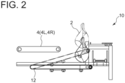
- FIG. 2 is a schematic side view of a meat processing apparatus 10 of FIG. 1 .
- the meat processing system 1 is a system for automatically conveying and processing a workpiece 2 which is meat.
- the workpiece 2 is meat including a bone part and a meat part, which may be pork, beef, horse meat, fish, or poultry.
- the meat processing system 1 includes a conveyance line 3, at least one processing station 7, and at least one meat processing apparatus 10.
- the conveyance line 3 is configured to convey the workpiece 2 to be processed, and has a conveyor 4 that can convey the workpiece supplied from a supply unit (not shown) located upstream to the processing station 7 or the meat processing apparatus 10 located downstream.
- the conveyor 4 receives the workpiece 2 from the supply unit at an inlet portion 5, which is at the upstream end.
- a pre-processing area 6, where workers can be positioned on both sides of the conveyor 4, is provided.
- the workpiece 2 can be pre-processed as appropriate at the stage prior to being processed in the processing station 7 or the meat processing apparatus 10 located downstream.
- the conveyor 4 is composed of a single lane at the relatively upstream side including the pre-processing area 6, the conveyor 4 splits into a left lane 4L and a right lane 4R in the middle, and the workpiece 2 conveyed from the upstream side is distributed to either the left lane 4L or the right lane 4R by a switching part 8.
- the left lane 4L and the right lane 4R are provided with respective processing stations 7 and meat processing apparatuses 10.
- the workpiece 2 processed in the processing station 7 and the meat processing apparatus 10 is conveyed through the conveyance lane to the outside.
- the processing station 7 receives the workpiece 2 from the conveyor 4 and processes the meat by a multi-axis robot (not shown) equipped with a meat processing tool.
- the meat processing in the processing station 7 is performed using a relatively small force, for example, as in conventional meat processing apparatuses for meat processing such as making an incision in a workpiece (for example, see JP4961613B , JP4867050B , JP5788076B , JP5788077B , or JP2022-170894A , etc.).
- processing stations 7 are provided along the left lane 4L and the right lane 4R each, but the number of processing stations 7 in each lane is not limited.
- the processing stations 7 may have the same configuration or different configurations.
- the meat processing apparatus 10 is a device for performing processing that requires a large force than in the processing station 7.
- the processing of pulling a meat part off the workpiece 2, which is meat including a bone part will be described as an example of such processing, but other processing may also be covered.
- the meat processing apparatus 10 receives the workpiece 2 conveyed by the conveyor 4 located at the upper stage, pulls off and separates the meat part from the workpiece 2.
- the meat part separated from the workpiece 2 is carried out by a discharge conveyor 11 located at the lower stage (the remaining workpiece 2 from which the meat part has been separated is returned to the conveyor 4 and conveyed to other downstream processes).
- the meat processing system 1 may be equipped with a controller for controlling each of the above components.
- the controller is one or more computing devices.
- a processor included in the computing device may be a CPU, a GPU, an MPU, a DSP, or a combination of these, or may be implemented by an integrated circuit such as a PLD, an ASIC, an FPGA, or an MCU.
- the computing device may include a memory such as a ROM, a RAM, or a flash memory, as appropriate.
- FIG. 3 is a schematic configuration diagram of the meat processing apparatus 10 of FIG. 1 .
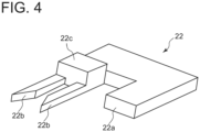
- FIG. 4 is an enlarged view of a tool 22 disposed at a tip portion 20 of a first robot arm 14 of FIG. 3 .
- the meat processing apparatus 10 has an apparatus body 12, a first robot arm 14, a second robot arm 16, and a meat separator 18.
- the apparatus body 12 is fixed to the floor on which the meat processing apparatus 10 is installed, and the configuration is not limited.
- the first robot arm 14 is a multi-axis robot installed in the apparatus body 12 and is movable based on a control signal from a controller (not shown).
- the first robot arm 14 has a robot structure with six or more axes so that the tool 22 mounted on the tip portion 20 can approach the workpiece 2 at any angle or orientation.
- the tool 22 disposed at the tip portion 20 of the first robot arm 14 includes at least a scraper 22a.
- the tool 22 is configured as a multitool including, in addition to the scraper 22a, a cutter 22b for making an incision in the workpiece 2.
- a cut can be formed in the workpiece 2 with the cutter 22b, and simultaneously the cut can be widened with the scraper 22a.
- the cutter 22b is attached to the body of the tool 22 via a cutter holder 22c.
- a vibration unit (not shown) for driving the cutter 22b is housed inside the cutter holder 22c.
- the second robot arm 16 is a multi-axis robot installed in the apparatus body 12 and is movable based on a control signal from a controller (not shown), as with the first robot arm 14.
- the second robot arm 16 also has a robot structure with six or more axes, and is configured to hold the workpiece 2 on the conveyor 4 by using a clamp part 26 mounted on a tip portion 24.
- the meat separator 18 is configured to be inserted into a cut formed in the workpiece 2 to pull the meat part off the workpiece 2. As described below, when inserting the meat separator 18, a cut formed in the workpiece 2 is widened by the scraper included in the tool 22 at the tip portion 20 of the first robot arm 14, so that the meat separator 18 is inserted into the cut accurately. Further, the meat separator 18 is opposite a holding member 19 that can be switched between a position retracted from the meat separator 18 (retracted position) and a position in proximity to the meat separator 18 for holding the workpiece 2 into which the meat separator 18 is inserted (holding position) by power from a drive source (not shown) ( FIG. 3 shows an example of the holding member 19 in the holding position.)
- Each of the first robot arm 14, the second robot arm 16, and the meat separator 18 is disposed separately from the apparatus body 12.
- FIG. 5 is a flowchart of operation flow of the meat processing apparatus 10 according to an embodiment.
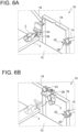
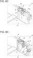
- FIGs. 6A o 6F are explanatory diagrams of operation corresponding to each step in FIG. 5 .
- step S1 the workpiece 2 conveyed by the conveyor 4 is detected (step S1), and the workpiece 2 is held by the second robot arm 16 (step S2), as shown in FIG. 6A .
- step S1 the workpiece 2 on the conveyor 4 is recognized by a detection sensor (not shown) to detect the workpiece 2 to be processed by the meat processing apparatus 10 and to identify its posture.
- step S2 on the basis of the detection result of step S1, the second robot arm 16 is operated relative to the workpiece 2 placed in a predetermined posture on the conveyor 4 to hold the workpiece 2 by the clamp part 26 at the tip portion 24 of the second robot arm 16.
- meat including leg parts of livestock is treated as the workpiece 2.
- the foot part of the workpiece 2 is identified by recognizing the shape of workpiece 2, and in step S2, the second robot arm 16 is operated to hold the identified foot part by the clamp part 26.
- the workpiece 2 held by the second robot arm 16 is placed in a posture (in this embodiment, in a suspended posture as shown in FIG. 6B ) suitable for processing performed in the subsequent step S3.
- step S3 the workpiece 2 held by the second robot arm 16 is processed by using the tool 22 at the tip portion 20 of the first robot arm 14 (step S3).
- the processing performed in step S3 is not limited, but in this embodiment, as one example, the workpiece 2 held in a suspended posture is subjected to an incision-making process by a cutter included in the tool 22.
- the meat separator 18 is inserted into the cut in the workpiece 2 widened by the scraper included in the tool 22 (step S4).
- the tool 22 is configured as a multitool including a scraper in addition to a cutter used for the processing of step S3. Therefore, in the processing of step S3, the tool 22 is used for the incision-making process with the cutter and simultaneously for widening the cut in the workpiece 2 with the scraper.
- the meat separator 18 is inserted into the cut thus widened by the scraper.
- the holding member 19 is rotated from the retracted position to the holding position so that the workpiece 2 is fixed between the meat separator 18 and the holding member 19, whereby the posture of the workpiece 2 is stabilized.
- Step S4 may include the step of pre-adjusting the position and posture of the workpiece 2 so that the position of the meat separator 18 corresponds to the position of the cut in the workpiece 2 widened by the scraper.
- the meat separator 18 is moved vertically relative to the workpiece 2 to pull the meat part off the workpiece 2 (step S5).
- the second robot arm 16 is operated to move the workpiece 2 held by the clamp part 26 at the tip portion 24 of the second robot arm 16.
- a large force is exerted between the workpiece 2 and the meat part which engages the meat separator 18 fixed to the apparatus body 12, so that the meat part can be pulled off the workpiece 2 effectively.
- step S6 the first robot arm 14 is operated to cut and separate the workpiece 2 pulled off in step S5 from the workpiece 2 by using the tool 22 at the tip portion 20 of the first robot arm 14 (step S6).
- step S5 the meat part is pulled off the workpiece 2, but the meat part is still partially connected to the workpiece 2. Therefore, in step S6, the connected portion is cut with the cutter included in the tool 22 to separate the pulled-off meat part from the workpiece 2.
- the separated meat part is carried out through the discharge conveyor 11 at the lower stage, as shown in FIG. 6G .
- the meat separator 18 is inserted into a cut in the workpiece 2 widened by the scraper included in the tool 22 disposed at the tip portion 20 of the first robot arm 14.
- the scraper included in the tool 22 disposed at the tip portion 20 of the first robot arm 14 By relative vertical movement of the workpiece 2 with the meat separator 18 thus inserted, a relatively large force can be exerted between the workpiece 2 and the meat to be pulled off, so that the meat can be pulled off the workpiece 2 efficiently.
- the tool 22 including the scraper disposed at the tip portion 20 of the first robot arm 14 can approach the workpiece 2 from various angles by changing the posture of the first robot arm 14.
- the present apparatus can be applied to workpieces 2 of various shapes.
Landscapes
- Life Sciences & Earth Sciences (AREA)
- Engineering & Computer Science (AREA)
- Wood Science & Technology (AREA)
- Zoology (AREA)
- Food Science & Technology (AREA)
- Manipulator (AREA)
- Processing Of Meat And Fish (AREA)
- Specific Conveyance Elements (AREA)
Abstract
Description
- The present disclosure relates to a meat processing apparatus and a meat processing system.
- A meat processing apparatus is known which automatically conveys and processes meat as a workpiece. For example, Patent Document 1 discloses a meat processing apparatus provided with a plurality of conveyors for conveying a workpiece. In this document, the workpiece conveyed by the conveyors is fed into an incision-making station.
- Patent Document 1:
WO2009/139031A - In a processing station equipped with a meat processing apparatus such as the one in Patent Document 1, a workpiece conveyed by a conveyor is processed while lying on the floor. In the processing station, the same hardware can be used to perform complex processing of various types and shapes by changing the software.
- Because such complex processing in the processing station requires a relatively little force from a robot arm used, it is difficult to perform processing that requires a large force, such as pulling meat off a workpiece, for example. Therefore, in order to pull meat off a workpiece in a conventional processing station, for example, the meat must be peeled off while gradually cutting it with a blade, which increases processing time and reduces yield since the knife-shaped blade must be inserted in a straight line against the round bone.
- In addition, because the processing is performed in the processing station with the workpiece in a lying position, it is difficult for a tool to approach the back surface of the workpiece (i.e., the side facing the floor).
- At least one embodiment of the present disclosure was made in view of the above, and an object thereof is to provide a meat processing apparatus and a meat processing system capable of efficiently performing processing that requires a relatively large force.
-
- (1) In order to solve the above problem, a meat processing apparatus according to at least one embodiment of the present disclosure includes: a first robot arm having a tool including a scraper at a tip portion; and a meat separator disposed separately from the first robot arm and configured to be inserted into a cut in a workpiece widened by the scraper and move vertically relative to the workpiece to pull a meat part off the workpiece.
According to the above aspect (1), the meat separator is inserted into a cut in a workpiece widened by the scraper disposed at the tip portion of the first robot arm. By relative vertical movement of the workpiece with the meat separator thus inserted, a relatively large force can be exerted between the workpiece and the meat to be pulled off, so that the meat can be pulled off the workpiece efficiently. Additionally, the scraper disposed at the tip portion of the first robot arm can approach the workpiece from various angles by changing the posture of the first robot arm. Thus, the present apparatus can be applied to workpieces of various shapes. - (2) In another aspect, in the above aspect (1), the tool is a multitool including a cutter for making an incision in the workpiece with the cut widened by the scraper.
According to the above aspect (2), the tool disposed at the tip portion of the first robot arm is configured as a multitool that includes functions of a scraper and a cutter. This allows efficient implementation of complex processing, such as making an incision in the workpiece with the cut widened by the scraper. - (3) In another aspect, in the above aspect (1) or (2), the apparatus further includes a second robot arm disposed separately from the first robot arm and having a clamp part at a tip portion for holding the workpiece. The first robot arm is configured to process the workpiece held by the clamp part using the tool.
According to the above aspect (3), the workpiece to be processed is held by the second robot arm, which is disposed separately from the first robot arm. The first robot arm processes the workpiece held by the second robot arm, enabling flexible implement of various complex processing by changing the posture of both robot arms. - (4) In another aspect, in the above aspect (3), the second robot arm is configured to move the workpiece while the meat separator inserted into the cut is fixed to pull off the meat part.
According to the above aspect (4), by moving the workpiece held by the second robot arm while the meat separator inserted into the cut widened by the scraper of the tool is fixed, a large force can be exerted between them. Thus, the meat part can be accurately pulled off the workpiece. - (5) In another aspect, in the above aspect (4), the tool is configured to cut the meat part pulled off to separate the meat part from the workpiece.
According to the above aspect (5), the pulled-off meat part can be easily separated from the workpiece by cutting the pulled-off meat part with the tool as described above. - (6) In another aspect, in the above aspect (1) or (2), the first robot arm has 6 or more axes.
According to the above aspect (6), since the first robot arm has six or more axes, the robot arm can operate flexibly, such as causing the tool at the tip portion to approach the workpiece at various angles, enabling various processing. - (7) In order to solve the above problem, a meat processing system according to one aspect includes: a conveyance line for conveying the workpiece; at least one processing station for processing the workpiece conveyed by the conveyance line; and the meat processing apparatus in the above aspect (1) or (2).
- According to the above aspect (7), since the above-described meat processing apparatus is combined with the processing station for processing the workpiece conveyed by the conveyance line, it is possible to achieve a meat processing system that can be widely used for processing operations where conventional processing stations do not have enough power or tools are difficult to approach.
- At least one embodiment of the present disclosure provides a meat processing apparatus and a meat processing system capable of efficiently performing processing that requires a relatively large force.
-
-
FIG. 1 is a schematic configuration diagram of a meat processing system according to an embodiment. -
FIG. 2 is a schematic side view of a meat processing apparatus ofFIG. 1 . -
FIG. 3 is a schematic configuration diagram of the meat processing apparatus ofFIG. 1 . -
FIG. 4 is an enlarged view of a tool disposed at a tip portion of a first robot arm ofFIG. 3 . -
FIG. 5 is a flowchart of operation flow of the meat processing apparatus according to an embodiment. -
FIG. 6A is an explanatory diagram of operation corresponding to each step inFIG. 5 . -
FIG. 6B is an explanatory diagram of operation corresponding to each step inFIG. 5 . -
FIG. 6C is an explanatory diagram of operation corresponding to each step inFIG. 5 . -
FIG. 6D is an explanatory diagram of operation corresponding to each step inFIG. 5 . -
FIG. 6E is an explanatory diagram of operation corresponding to each step inFIG. 5 . -
FIG. 6F is an explanatory diagram of operation corresponding to each step inFIG. 5 . -
FIG. 6G is an explanatory diagram of operation corresponding to each step inFIG. 5 . - Embodiments of the present invention will now be described in detail with reference to the accompanying drawings. It is intended, however, that unless particularly identified, dimensions, materials, shapes, relative positions, and the like of components described in the embodiments shall be interpreted as illustrative only and not intended to limit the scope of the present invention.
-
FIG. 1 is a schematic configuration diagram of a meat processing system 1 according to an embodiment.FIG. 2 is a schematic side view of ameat processing apparatus 10 ofFIG. 1 . The meat processing system 1 is a system for automatically conveying and processing aworkpiece 2 which is meat. Theworkpiece 2 is meat including a bone part and a meat part, which may be pork, beef, horse meat, fish, or poultry. - The meat processing system 1 includes a conveyance line 3, at least one
processing station 7, and at least onemeat processing apparatus 10. - The conveyance line 3 is configured to convey the
workpiece 2 to be processed, and has aconveyor 4 that can convey the workpiece supplied from a supply unit (not shown) located upstream to theprocessing station 7 or themeat processing apparatus 10 located downstream. Theconveyor 4 receives theworkpiece 2 from the supply unit at aninlet portion 5, which is at the upstream end. In the vicinity of theinlet portion 5, apre-processing area 6, where workers can be positioned on both sides of theconveyor 4, is provided. In thepre-processing area 6, theworkpiece 2 can be pre-processed as appropriate at the stage prior to being processed in theprocessing station 7 or themeat processing apparatus 10 located downstream. - Although the
conveyor 4 is composed of a single lane at the relatively upstream side including thepre-processing area 6, theconveyor 4 splits into aleft lane 4L and aright lane 4R in the middle, and theworkpiece 2 conveyed from the upstream side is distributed to either theleft lane 4L or theright lane 4R by a switching part 8. Theleft lane 4L and theright lane 4R are provided withrespective processing stations 7 andmeat processing apparatuses 10. Theworkpiece 2 processed in theprocessing station 7 and themeat processing apparatus 10 is conveyed through the conveyance lane to the outside. - The
processing station 7 receives theworkpiece 2 from theconveyor 4 and processes the meat by a multi-axis robot (not shown) equipped with a meat processing tool. The meat processing in theprocessing station 7 is performed using a relatively small force, for example, as in conventional meat processing apparatuses for meat processing such as making an incision in a workpiece (for example, seeJP4961613B JP4867050B JP5788076B JP5788077B JP2022-170894A - In this embodiment, two
processing stations 7 are provided along theleft lane 4L and theright lane 4R each, but the number ofprocessing stations 7 in each lane is not limited. Theprocessing stations 7 may have the same configuration or different configurations. - The
meat processing apparatus 10 is a device for performing processing that requires a large force than in theprocessing station 7. In this embodiment, the processing of pulling a meat part off theworkpiece 2, which is meat including a bone part, will be described as an example of such processing, but other processing may also be covered. As shown inFIG. 2 , themeat processing apparatus 10 receives theworkpiece 2 conveyed by theconveyor 4 located at the upper stage, pulls off and separates the meat part from theworkpiece 2. The meat part separated from theworkpiece 2 is carried out by a discharge conveyor 11 located at the lower stage (the remainingworkpiece 2 from which the meat part has been separated is returned to theconveyor 4 and conveyed to other downstream processes). - The meat processing system 1 may be equipped with a controller for controlling each of the above components. The controller is one or more computing devices. A processor included in the computing device may be a CPU, a GPU, an MPU, a DSP, or a combination of these, or may be implemented by an integrated circuit such as a PLD, an ASIC, an FPGA, or an MCU. The computing device may include a memory such as a ROM, a RAM, or a flash memory, as appropriate.
- Next, a specific configuration of the
meat processing apparatus 10 will be described.FIG. 3 is a schematic configuration diagram of themeat processing apparatus 10 ofFIG. 1 .FIG. 4 is an enlarged view of atool 22 disposed at atip portion 20 of afirst robot arm 14 ofFIG. 3 . - The
meat processing apparatus 10 has anapparatus body 12, afirst robot arm 14, asecond robot arm 16, and ameat separator 18. - The
apparatus body 12 is fixed to the floor on which themeat processing apparatus 10 is installed, and the configuration is not limited. - The
first robot arm 14 is a multi-axis robot installed in theapparatus body 12 and is movable based on a control signal from a controller (not shown). Thefirst robot arm 14 has a robot structure with six or more axes so that thetool 22 mounted on thetip portion 20 can approach theworkpiece 2 at any angle or orientation. - The
tool 22 disposed at thetip portion 20 of thefirst robot arm 14 includes at least ascraper 22a. In this embodiment, as illustrated inFIG. 4 , thetool 22 is configured as a multitool including, in addition to thescraper 22a, acutter 22b for making an incision in theworkpiece 2. By using thetool 22, a cut can be formed in theworkpiece 2 with thecutter 22b, and simultaneously the cut can be widened with thescraper 22a. - The
cutter 22b is attached to the body of thetool 22 via acutter holder 22c. A vibration unit (not shown) for driving thecutter 22b is housed inside thecutter holder 22c. - The
second robot arm 16 is a multi-axis robot installed in theapparatus body 12 and is movable based on a control signal from a controller (not shown), as with thefirst robot arm 14. Thesecond robot arm 16 also has a robot structure with six or more axes, and is configured to hold theworkpiece 2 on theconveyor 4 by using aclamp part 26 mounted on atip portion 24. - The
meat separator 18 is configured to be inserted into a cut formed in theworkpiece 2 to pull the meat part off theworkpiece 2. As described below, when inserting themeat separator 18, a cut formed in theworkpiece 2 is widened by the scraper included in thetool 22 at thetip portion 20 of thefirst robot arm 14, so that themeat separator 18 is inserted into the cut accurately. Further, themeat separator 18 is opposite a holdingmember 19 that can be switched between a position retracted from the meat separator 18 (retracted position) and a position in proximity to themeat separator 18 for holding theworkpiece 2 into which themeat separator 18 is inserted (holding position) by power from a drive source (not shown) (FIG. 3 shows an example of the holdingmember 19 in the holding position.) - Each of the
first robot arm 14, thesecond robot arm 16, and themeat separator 18 is disposed separately from theapparatus body 12. - Next, the operation of the
meat processing apparatus 10 having the above configuration will be described.FIG. 5 is a flowchart of operation flow of themeat processing apparatus 10 according to an embodiment.FIGs. 6A o6F are explanatory diagrams of operation corresponding to each step inFIG. 5 . - First, the
workpiece 2 conveyed by theconveyor 4 is detected (step S1), and theworkpiece 2 is held by the second robot arm 16 (step S2), as shown inFIG. 6A . In step S1, theworkpiece 2 on theconveyor 4 is recognized by a detection sensor (not shown) to detect theworkpiece 2 to be processed by themeat processing apparatus 10 and to identify its posture. In step S2, on the basis of the detection result of step S1, thesecond robot arm 16 is operated relative to theworkpiece 2 placed in a predetermined posture on theconveyor 4 to hold theworkpiece 2 by theclamp part 26 at thetip portion 24 of thesecond robot arm 16. - In this embodiment, meat including leg parts of livestock is treated as the
workpiece 2. In step S1, the foot part of theworkpiece 2 is identified by recognizing the shape ofworkpiece 2, and in step S2, thesecond robot arm 16 is operated to hold the identified foot part by theclamp part 26. - The
workpiece 2 held by thesecond robot arm 16 is placed in a posture (in this embodiment, in a suspended posture as shown inFIG. 6B ) suitable for processing performed in the subsequent step S3. - Then, as shown in
FIG. 6C , theworkpiece 2 held by thesecond robot arm 16 is processed by using thetool 22 at thetip portion 20 of the first robot arm 14 (step S3). The processing performed in step S3 is not limited, but in this embodiment, as one example, theworkpiece 2 held in a suspended posture is subjected to an incision-making process by a cutter included in thetool 22. - Then, as shown in
FIG. 6D , themeat separator 18 is inserted into the cut in theworkpiece 2 widened by the scraper included in the tool 22 (step S4). As described above, thetool 22 is configured as a multitool including a scraper in addition to a cutter used for the processing of step S3. Therefore, in the processing of step S3, thetool 22 is used for the incision-making process with the cutter and simultaneously for widening the cut in theworkpiece 2 with the scraper. In step S4, themeat separator 18 is inserted into the cut thus widened by the scraper. While themeat separator 18 is inserted into the cut in theworkpiece 2, the holdingmember 19 is rotated from the retracted position to the holding position so that theworkpiece 2 is fixed between themeat separator 18 and the holdingmember 19, whereby the posture of theworkpiece 2 is stabilized. - Step S4 may include the step of pre-adjusting the position and posture of the
workpiece 2 so that the position of themeat separator 18 corresponds to the position of the cut in theworkpiece 2 widened by the scraper. - Then, as shown in
FIG. 6E , themeat separator 18 is moved vertically relative to theworkpiece 2 to pull the meat part off the workpiece 2 (step S5). In this embodiment, while themeat separator 18 inserted into the cut widened by the scraper is fixed to theapparatus body 12, thesecond robot arm 16 is operated to move theworkpiece 2 held by theclamp part 26 at thetip portion 24 of thesecond robot arm 16. As a result, a large force is exerted between theworkpiece 2 and the meat part which engages themeat separator 18 fixed to theapparatus body 12, so that the meat part can be pulled off theworkpiece 2 effectively. - Then, as shown in
FIG. 6F , thefirst robot arm 14 is operated to cut and separate theworkpiece 2 pulled off in step S5 from theworkpiece 2 by using thetool 22 at thetip portion 20 of the first robot arm 14 (step S6). In step S5, the meat part is pulled off theworkpiece 2, but the meat part is still partially connected to theworkpiece 2. Therefore, in step S6, the connected portion is cut with the cutter included in thetool 22 to separate the pulled-off meat part from theworkpiece 2. - The separated meat part is carried out through the discharge conveyor 11 at the lower stage, as shown in
FIG. 6G . - As described above, according to the above-described embodiment, the
meat separator 18 is inserted into a cut in theworkpiece 2 widened by the scraper included in thetool 22 disposed at thetip portion 20 of thefirst robot arm 14. By relative vertical movement of theworkpiece 2 with themeat separator 18 thus inserted, a relatively large force can be exerted between theworkpiece 2 and the meat to be pulled off, so that the meat can be pulled off theworkpiece 2 efficiently. Additionally, thetool 22 including the scraper disposed at thetip portion 20 of thefirst robot arm 14 can approach theworkpiece 2 from various angles by changing the posture of thefirst robot arm 14. Thus, the present apparatus can be applied toworkpieces 2 of various shapes. -
- 1
- Meat processing system
- 2
- Workpiece
- 3
- Conveyance line
- 4
- Conveyor
- 4L
- Left lane
- 4R
- Right lane
- 5
- Inlet portion
- 6
- Pre-processing area
- 7
- Processing station
- 8
- Switching part
- 10
- Meat processing apparatus
- 11
- Discharge conveyor
- 12
- Apparatus body
- 14
- First robot arm
- 16
- Second robot arm
- 18
- Meat separator
- 19
- Holding member
- 20
- Tip portion
- 22
- Tool
- 24
- Tip portion
- 26
- Clamp part
Claims (7)
- A meat processing apparatus, comprising:a first robot arm having a tool including a scraper at a tip portion; anda meat separator disposed separately from the first robot arm and configured to be inserted into a cut in a workpiece widened by the scraper and move vertically relative to the workpiece to pull a meat part off the workpiece.
- The meat processing apparatus according to claim 1,
wherein the tool is a multitool including a cutter for making an incision in the workpiece with the cut widened by the scraper. - The meat processing apparatus according to claim 1 or 2, further comprising a second robot arm disposed separately from the first robot arm and having a clamp part at a tip portion for holding the workpiece,
wherein the first robot arm is configured to process the workpiece held by the clamp part using the tool. - The meat processing apparatus according to claim 3,
wherein the second robot arm is configured to move the workpiece while the meat separator inserted into the cut is fixed to pull off the meat part. - The meat processing apparatus according to claim 4,
wherein the tool is configured to cut the meat part pulled off to separate the meat part from the workpiece. - The meat processing apparatus according to claim 1 or 2,
wherein the first robot arm has 6 or more axes. - A meat processing system, comprising:a conveyance line for conveying the workpiece;at least one processing station for processing the workpiece conveyed by the conveyance line; andthe meat processing apparatus according to claim 1 or 2.
Applications Claiming Priority (2)
| Application Number | Priority Date | Filing Date | Title |
|---|---|---|---|
| JP2022211037A JP2024094481A (en) | 2022-12-28 | 2022-12-28 | Meat processing equipment and meat processing system |
| PCT/JP2023/044759 WO2024142955A1 (en) | 2022-12-28 | 2023-12-14 | Meat processing device and meat processing system |
Publications (2)
| Publication Number | Publication Date |
|---|---|
| EP4470380A1 true EP4470380A1 (en) | 2024-12-04 |
| EP4470380A4 EP4470380A4 (en) | 2025-08-06 |
Family
ID=91717769
Family Applications (1)
| Application Number | Title | Priority Date | Filing Date |
|---|---|---|---|
| EP23911736.9A Pending EP4470380A4 (en) | 2022-12-28 | 2023-12-14 | MEAT PROCESSING DEVICE AND MEAT PROCESSING SYSTEM |
Country Status (5)
| Country | Link |
|---|---|
| US (1) | US20250176567A1 (en) |
| EP (1) | EP4470380A4 (en) |
| JP (1) | JP2024094481A (en) |
| CN (1) | CN120344152A (en) |
| WO (1) | WO2024142955A1 (en) |
Families Citing this family (1)
| Publication number | Priority date | Publication date | Assignee | Title |
|---|---|---|---|---|
| JP7732768B2 (en) * | 2021-04-30 | 2025-09-02 | 株式会社前川製作所 | Meat processing equipment |
Family Cites Families (22)
| Publication number | Priority date | Publication date | Assignee | Title |
|---|---|---|---|---|
| CA1322438C (en) * | 1988-10-31 | 1993-09-28 | Jacobus E. Hazenbroek | Revolving poultry thigh deboner |
| NL1012703C2 (en) * | 1999-04-06 | 2000-10-09 | Stork Pmt | Method and device for processing a poultry leg. |
| JP4190705B2 (en) * | 2000-06-30 | 2008-12-03 | 株式会社前川製作所 | Thigh meat separation method and apparatus |
| ATE475319T1 (en) * | 2003-04-04 | 2010-08-15 | Schill Maja Masch | DEVICE FOR DELINDING OR TRIMING A PIECE OF MEAT OR A PIECE OF SLAUGHTER ANIMAL |
| NL1024963C2 (en) * | 2003-12-08 | 2005-06-09 | Humboldt B V | Method and device for releasing a bone part from a carcass part. |
| JP4126027B2 (en) * | 2004-04-16 | 2008-07-30 | 食肉生産技術研究組合 | Spinal column removal method and spinal column removal device |
| WO2008096459A1 (en) | 2007-02-06 | 2008-08-14 | Mayekawa Mfg. Co., Ltd. | Method and apparatus for deboning arm or leg part |
| JP4867050B2 (en) | 2007-05-02 | 2012-02-01 | 株式会社前川製作所 | Method and apparatus for creasing meat for livestock carcass and cutting operation program for creasing |
| WO2009139031A1 (en) | 2008-05-12 | 2009-11-19 | 株式会社前川製作所 | Loading method and loading device of meat with bone and loading operation program |
| NL2005027C2 (en) * | 2010-07-05 | 2012-01-09 | Meyn Food Proc Technology Bv | A method and device for slitting a chicken leg. |
| NL2007744C2 (en) * | 2011-11-08 | 2013-05-13 | Humboldt B V | DEVICE AND METHOD FOR PROCESSING BIG CATTLE CARCASES |
| JP5788076B2 (en) | 2012-03-13 | 2015-09-30 | 株式会社前川製作所 | Bone meat scapula removing device and method, and bone-equipped meat deboning system including the device |
| WO2013136996A1 (en) | 2012-03-13 | 2013-09-19 | 株式会社前川製作所 | Deboning system for foreleg portion of meat on the bone, and deboning method |
| CA3019818A1 (en) * | 2014-05-01 | 2015-11-05 | Jarvis Products Corporation | Robotic carcass processing method and system |
| DK3157343T3 (en) * | 2014-06-18 | 2019-03-04 | Marel Stork Poultry Proc Bv | Method and plant for the extraction of knee meat and thigh meat from a poultry |
| KR101896854B1 (en) * | 2014-06-30 | 2018-09-07 | 가부시끼가이샤 마에가와 세이사꾸쇼 | Chicken-tenderloin extraction device |
| NL2018150B1 (en) * | 2017-01-10 | 2018-07-25 | Humboldt Bv | Method and device for processing carcasses of livestock along the spine |
| US11191281B1 (en) * | 2018-01-05 | 2021-12-07 | Tyson Foods, Inc. | Method and apparatus for conveying a meat product and using an ultrasonic knife for automated cutting of meat |
| JP7129173B2 (en) * | 2018-02-14 | 2022-09-01 | 株式会社前川製作所 | Device for separating leg meat with bones and method for separating leg meat with bones |
| CN113163775B (en) * | 2018-11-22 | 2023-06-27 | 洪堡有限公司 | Method and device for locating and/or handling carcasses and/or carcass parts during slaughter of animals on an industrial scale |
| JP7526031B2 (en) * | 2020-05-12 | 2024-07-31 | 株式会社前川製作所 | Workpiece measuring device and creasing system |
| JP7732768B2 (en) | 2021-04-30 | 2025-09-02 | 株式会社前川製作所 | Meat processing equipment |
-
2022
- 2022-12-28 JP JP2022211037A patent/JP2024094481A/en active Pending
-
2023
- 2023-12-14 CN CN202380088065.3A patent/CN120344152A/en active Pending
- 2023-12-14 EP EP23911736.9A patent/EP4470380A4/en active Pending
- 2023-12-14 US US18/840,534 patent/US20250176567A1/en active Pending
- 2023-12-14 WO PCT/JP2023/044759 patent/WO2024142955A1/en not_active Ceased
Also Published As
| Publication number | Publication date |
|---|---|
| EP4470380A4 (en) | 2025-08-06 |
| CN120344152A (en) | 2025-07-18 |
| JP2024094481A (en) | 2024-07-10 |
| WO2024142955A1 (en) | 2024-07-04 |
| US20250176567A1 (en) | 2025-06-05 |
Similar Documents
| Publication | Publication Date | Title |
|---|---|---|
| JP5057407B2 (en) | Deboning method and apparatus for livestock carcass for meat | |
| KR101896854B1 (en) | Chicken-tenderloin extraction device | |
| US20250176567A1 (en) | Meat processing apparatus and meat processing system | |
| CN113163775A (en) | Method and device for positioning and/or handling carcasses and/or carcass parts during slaughter of animals on an industrial scale | |
| EP2258202A3 (en) | Method and device for processing a carcass part of slaughtered poultry | |
| KR20180059503A (en) | Sensor-guided automation methods and systems for processing crustaceans | |
| JPWO2009139031A1 (en) | Mounting method and apparatus for meat with bone, and operation program for mounting | |
| US11596156B2 (en) | Method and device for processing carcasses of livestock along the spine | |
| EP3550982B1 (en) | A method of processing a food object | |
| KR102331415B1 (en) | Boneless leg meat processing system and manufacturing method of separated meat | |
| TW201929674A (en) | Device for measuring entire length of bone-in meat and method for measuring entire length of bone-in meat | |
| US10278401B2 (en) | System for automatically loosening or removing shoulder blades from shoulders of carcasses | |
| JP4867050B2 (en) | Method and apparatus for creasing meat for livestock carcass and cutting operation program for creasing | |
| JP2018060642A (en) | Wire processing device | |
| US20240389607A1 (en) | Foodstuff trimming device, and foodstuff trimming system | |
| US20240389608A1 (en) | Poultry processing apparatus | |
| EP0723836A1 (en) | Process and device for the application of components which are strung together in the manner of a belt onto workpieces | |
| DE50312736D1 (en) | Method and device for processing and separating a scale-like formation of flexible, flat objects | |
| CN121729142A (en) | Workpiece holding device and workpiece holding method | |
| KR790001441B1 (en) | Auto-incision apaaratus for fish abdomen | |
| JPH06153774A (en) | Apparatus for removing fat in fish eye socket |
Legal Events
| Date | Code | Title | Description |
|---|---|---|---|
| STAA | Information on the status of an ep patent application or granted ep patent |
Free format text: STATUS: THE INTERNATIONAL PUBLICATION HAS BEEN MADE |
|
| PUAI | Public reference made under article 153(3) epc to a published international application that has entered the european phase |
Free format text: ORIGINAL CODE: 0009012 |
|
| STAA | Information on the status of an ep patent application or granted ep patent |
Free format text: STATUS: REQUEST FOR EXAMINATION WAS MADE |
|
| 17P | Request for examination filed |
Effective date: 20240826 |
|
| AK | Designated contracting states |
Kind code of ref document: A1 Designated state(s): AL AT BE BG CH CY CZ DE DK EE ES FI FR GB GR HR HU IE IS IT LI LT LU LV MC ME MK MT NL NO PL PT RO RS SE SI SK SM TR |
|
| A4 | Supplementary search report drawn up and despatched |
Effective date: 20250703 |
|
| RIC1 | Information provided on ipc code assigned before grant |
Ipc: A22C 21/00 20060101AFI20250627BHEP Ipc: A22C 17/00 20060101ALI20250627BHEP |
|
| STAA | Information on the status of an ep patent application or granted ep patent |
Free format text: STATUS: EXAMINATION IS IN PROGRESS |
|
| DAV | Request for validation of the european patent (deleted) | ||
| DAX | Request for extension of the european patent (deleted) | ||
| 17Q | First examination report despatched |
Effective date: 20260313 |