EP4467922A1 - Plate test device and method, and winding device - Google Patents
Plate test device and method, and winding device Download PDFInfo
- Publication number
- EP4467922A1 EP4467922A1 EP23802655.3A EP23802655A EP4467922A1 EP 4467922 A1 EP4467922 A1 EP 4467922A1 EP 23802655 A EP23802655 A EP 23802655A EP 4467922 A1 EP4467922 A1 EP 4467922A1
- Authority
- EP
- European Patent Office
- Prior art keywords
- electrode plate
- sub
- combined
- electrode
- distance
- Prior art date
- Legal status (The legal status is an assumption and is not a legal conclusion. Google has not performed a legal analysis and makes no representation as to the accuracy of the status listed.)
- Pending
Links
Images


Classifications
-
- H—ELECTRICITY
- H01—ELECTRIC ELEMENTS
- H01M—PROCESSES OR MEANS, e.g. BATTERIES, FOR THE DIRECT CONVERSION OF CHEMICAL ENERGY INTO ELECTRICAL ENERGY
- H01M10/00—Secondary cells; Manufacture thereof
- H01M10/04—Construction or manufacture in general
- H01M10/0404—Machines for assembling batteries
- H01M10/0409—Machines for assembling batteries for cells with wound electrodes
-
- G—PHYSICS
- G01—MEASURING; TESTING
- G01B—MEASURING LENGTH, THICKNESS OR SIMILAR LINEAR DIMENSIONS; MEASURING ANGLES; MEASURING AREAS; MEASURING IRREGULARITIES OF SURFACES OR CONTOURS
- G01B21/00—Measuring arrangements or details thereof, where the measuring technique is not covered by the other groups of this subclass, unspecified or not relevant
- G01B21/16—Measuring arrangements or details thereof, where the measuring technique is not covered by the other groups of this subclass, unspecified or not relevant for measuring distance of clearance between spaced objects
-
- H—ELECTRICITY
- H01—ELECTRIC ELEMENTS
- H01M—PROCESSES OR MEANS, e.g. BATTERIES, FOR THE DIRECT CONVERSION OF CHEMICAL ENERGY INTO ELECTRICAL ENERGY
- H01M10/00—Secondary cells; Manufacture thereof
- H01M10/05—Accumulators with non-aqueous electrolyte
- H01M10/058—Construction or manufacture
- H01M10/0587—Construction or manufacture of accumulators having only wound construction elements, i.e. wound positive electrodes, wound negative electrodes and wound separators
-
- G—PHYSICS
- G01—MEASURING; TESTING
- G01B—MEASURING LENGTH, THICKNESS OR SIMILAR LINEAR DIMENSIONS; MEASURING ANGLES; MEASURING AREAS; MEASURING IRREGULARITIES OF SURFACES OR CONTOURS
- G01B11/00—Measuring arrangements characterised by the use of optical techniques
- G01B11/14—Measuring arrangements characterised by the use of optical techniques for measuring distance or clearance between spaced objects or spaced apertures
-
- G—PHYSICS
- G01—MEASURING; TESTING
- G01N—INVESTIGATING OR ANALYSING MATERIALS BY DETERMINING THEIR CHEMICAL OR PHYSICAL PROPERTIES
- G01N21/00—Investigating or analysing materials by the use of optical means, i.e. using sub-millimetre waves, infrared, visible or ultraviolet light
- G01N21/17—Systems in which incident light is modified in accordance with the properties of the material investigated
- G01N21/25—Colour; Spectral properties, i.e. comparison of effect of material on the light at two or more different wavelengths or wavelength bands
-
- H—ELECTRICITY
- H01—ELECTRIC ELEMENTS
- H01M—PROCESSES OR MEANS, e.g. BATTERIES, FOR THE DIRECT CONVERSION OF CHEMICAL ENERGY INTO ELECTRICAL ENERGY
- H01M10/00—Secondary cells; Manufacture thereof
- H01M10/04—Construction or manufacture in general
-
- H—ELECTRICITY
- H01—ELECTRIC ELEMENTS
- H01M—PROCESSES OR MEANS, e.g. BATTERIES, FOR THE DIRECT CONVERSION OF CHEMICAL ENERGY INTO ELECTRICAL ENERGY
- H01M10/00—Secondary cells; Manufacture thereof
- H01M10/04—Construction or manufacture in general
- H01M10/0431—Cells with wound or folded electrodes
-
- H—ELECTRICITY
- H01—ELECTRIC ELEMENTS
- H01M—PROCESSES OR MEANS, e.g. BATTERIES, FOR THE DIRECT CONVERSION OF CHEMICAL ENERGY INTO ELECTRICAL ENERGY
- H01M10/00—Secondary cells; Manufacture thereof
- H01M10/05—Accumulators with non-aqueous electrolyte
-
- G—PHYSICS
- G01—MEASURING; TESTING
- G01B—MEASURING LENGTH, THICKNESS OR SIMILAR LINEAR DIMENSIONS; MEASURING ANGLES; MEASURING AREAS; MEASURING IRREGULARITIES OF SURFACES OR CONTOURS
- G01B11/00—Measuring arrangements characterised by the use of optical techniques
- G01B11/02—Measuring arrangements characterised by the use of optical techniques for measuring length, width or thickness
- G01B11/022—Measuring arrangements characterised by the use of optical techniques for measuring length, width or thickness by means of tv-camera scanning
-
- G—PHYSICS
- G01—MEASURING; TESTING
- G01B—MEASURING LENGTH, THICKNESS OR SIMILAR LINEAR DIMENSIONS; MEASURING ANGLES; MEASURING AREAS; MEASURING IRREGULARITIES OF SURFACES OR CONTOURS
- G01B11/00—Measuring arrangements characterised by the use of optical techniques
- G01B11/02—Measuring arrangements characterised by the use of optical techniques for measuring length, width or thickness
- G01B11/04—Measuring arrangements characterised by the use of optical techniques for measuring length, width or thickness specially adapted for measuring length or width of objects while moving
- G01B11/043—Measuring arrangements characterised by the use of optical techniques for measuring length, width or thickness specially adapted for measuring length or width of objects while moving for measuring length
-
- G—PHYSICS
- G01—MEASURING; TESTING
- G01N—INVESTIGATING OR ANALYSING MATERIALS BY DETERMINING THEIR CHEMICAL OR PHYSICAL PROPERTIES
- G01N21/00—Investigating or analysing materials by the use of optical means, i.e. using sub-millimetre waves, infrared, visible or ultraviolet light
- G01N21/84—Systems specially adapted for particular applications
- G01N21/88—Investigating the presence of flaws or contamination
- G01N21/89—Investigating the presence of flaws or contamination in moving material, e.g. running paper or textiles
-
- Y—GENERAL TAGGING OF NEW TECHNOLOGICAL DEVELOPMENTS; GENERAL TAGGING OF CROSS-SECTIONAL TECHNOLOGIES SPANNING OVER SEVERAL SECTIONS OF THE IPC; TECHNICAL SUBJECTS COVERED BY FORMER USPC CROSS-REFERENCE ART COLLECTIONS [XRACs] AND DIGESTS
- Y02—TECHNOLOGIES OR APPLICATIONS FOR MITIGATION OR ADAPTATION AGAINST CLIMATE CHANGE
- Y02E—REDUCTION OF GREENHOUSE GAS [GHG] EMISSIONS, RELATED TO ENERGY GENERATION, TRANSMISSION OR DISTRIBUTION
- Y02E60/00—Enabling technologies; Technologies with a potential or indirect contribution to GHG emissions mitigation
- Y02E60/10—Energy storage using batteries
-
- Y—GENERAL TAGGING OF NEW TECHNOLOGICAL DEVELOPMENTS; GENERAL TAGGING OF CROSS-SECTIONAL TECHNOLOGIES SPANNING OVER SEVERAL SECTIONS OF THE IPC; TECHNICAL SUBJECTS COVERED BY FORMER USPC CROSS-REFERENCE ART COLLECTIONS [XRACs] AND DIGESTS
- Y02—TECHNOLOGIES OR APPLICATIONS FOR MITIGATION OR ADAPTATION AGAINST CLIMATE CHANGE
- Y02P—CLIMATE CHANGE MITIGATION TECHNOLOGIES IN THE PRODUCTION OR PROCESSING OF GOODS
- Y02P70/00—Climate change mitigation technologies in the production process for final industrial or consumer products
- Y02P70/50—Manufacturing or production processes characterised by the final manufactured product
Definitions
- the present application relates to the field of inspection technology, and in particular to an electrode plate inspection device and method, and a winding device.
- the battery refers to a physical module that includes one or more battery cells to supply electric energy.
- the battery cell includes an electrode assembly composed of electrode plates and a separator.
- the quality of the electrode plate is closely related to the quality of the battery. Therefore, how to effectively inspect the electrode plate is an urgent problem to be solved.
- Embodiments of the present application provide an electrode plate inspection device and method, and a winding device, which can enable effective inspection of an electrode plate, thereby improving the quality of the electrode plate.
- an electrode plate inspection device including: a combining unit is configured to combine a separator on a side of a first electrode plate in a thickness direction of the first electrode plate, the first electrode plate including at least two sub-electrode plates arranged at intervals in a conveying direction of the first electrode plate; a measuring unit arranged downstream of the combining unit in the conveying direction, and configured to measure a first distance between two adjacent combined sub-electrode plates in the conveying direction; and a processing unit configured to determine whether the combined first electrode plate is qualified according to the first distance.
- At least two electrode plates are arranged at intervals, and the distance between two adjacent electrode plates affects the quality of the battery. For example, if the electrode plate is subsequently subjected to a winding operation and the distance between two adjacent electrode plates is not appropriate, a corner of the electrode plate may be wrinkled, thereby seriously affecting the energy density, service life and other performances of the battery. Therefore, determining whether an electrode plate is qualified according to the distance between two adjacent electrode plates can enable effective inspection of the electrode plate, improving the quality of the electrode plate, thereby improving the performance of the battery composed of this electrode plate.
- the separator includes a first separator and a second separator, and the electrode plate and the separator are combined in advance, so that the problem of misalignment between the first separator and the second separator during subsequent operations can be reduced, and the quality of the electrode plate can thus be further improved.
- the measuring unit further includes a sensor configured to obtain positions of the combined sub-electrode plates; and the processing unit is configured to determine whether the combined first electrode plate is qualified according to the positions and the first distance.
- a sensor configured to obtain positions of the combined sub-electrode plates is added in the electrode plate inspection device, and whether the first electrode plate is qualified is determined according to the positions of the combined sub-electrode plates in addition to the first distance. That is, whether the first electrode plate is qualified is determined according to multiple parameters, so that the inspection accuracy of the electrode plate can be improved, further improving the quality of the electrode plate and the battery composed of this electrode plate.
- the senor is a color mark sensor, a color mark is provided at an end of each sub-electrode plate, and the color mark sensor is configured to obtain the positions of the sub-electrode plates by sensing the color marks.
- the color mark sensor since a color mark is provided at an end of each sub-electrode plate, and the color mark sensor obtains the positions of the sub-electrode plates by sensing the color marks, the positions of the sub-electrode plates can be determined with a high accuracy.
- the sensor which is configured as a color mark sensor, is less costly.
- the sub-electrode plates include a first sub-electrode plate and a second sub-electrode plate adjacent to each other, the second sub-electrode plate is located downstream of the first sub-electrode plate in the conveying direction, and the first distance is a distance between the first sub-electrode plate and the second sub-electrode plate; wherein the sensor is a color mark sensor configured to obtain the position of the second sub-electrode plate by sensing a color between the first sub-electrode plate and a preset position, the preset position being a preset position of the combined second sub-electrode plate; and the processing unit is configured to determine whether the combined first electrode plate is qualified according to the first distance and the color sensed by the color mark sensor.
- the processing unit to implement the determination of whether the first electrode plate is qualified according to the first distance and the color sensed by the color mark sensor; and compared with determining whether the first electrode plate is qualified according to one parameter (i.e., the first distance), determining whether the first electrode plate is qualified according to multiple parameters (i.e., the first distance and the color sensed by the color mark sensor) can improve the accuracy of determining whether the first electrode plate is qualified to some extent, further improving the quality of the electrode plate and the battery composed of this electrode plate.
- the sensor which is configured as a color mark sensor, is less costly.
- the processing unit is configured to determine whether the combined first electrode plate is qualified according to the first distance when the color sensed by the color mark sensor is the same as the color of the separator.
- the color sensed by the color mark sensor is the same as the color of the separator, it is indicated that the position of the first sub-electrode plate is the same as the preset position, that is, the absolute position of the first sub-electrode plate is accurate. In this case, determining whether the combined first electrode plate is qualified according to the first distance contributes to further improving the inspection accuracy of the electrode plate.
- a speed sensor configured to detect a moving speed of the first electrode plate in the conveying direction
- a timer configured to measure the time it takes for the second sub-electrode plate to be conveyed to the preset position; wherein after it is determined that the second sub-electrode plate reaches the preset position according to the moving speed and the time, the color mark sensor is configured to sense the color between the first sub-electrode plate and the preset position.
- whether the second sub-electrode plate reaches the preset position is determined by means of the speed sensor and the timer, so that the accuracy of determining whether the second sub-electrode plate reaches the preset position is high, and the color mark sensor can start sensing the color between the first sub-electrode plate and the preset position at an accurate time, thereby further improving the inspection accuracy of the electrode plate.
- the processing unit is configured to determine whether the combined first electrode plate is qualified according to a deviation between the first distance and a predetermined distance.
- the combining unit when the combined first electrode plate is qualified, is further configured to combine a continuous sub-electrode plate with the separator, the first electrode plate including the continuous sub-electrode plate, and the continuous sub-electrode plate being a continuous electrode plate combined after the at least two sub-electrode plates.
- the first electrode plate in the above technical solution further includes a continuous sub-electrode plate, which can improve the performance of the battery, for example, increasing the energy density of the battery.
- a removing unit configured, when the combined first electrode plate is unqualified, to remove the combined first electrode plate.
- the removal of the unqualified first electrode plate can significantly increase the removal rate of unqualified products and thus improve the product quality of the battery.
- a winding device including: an electrode plate inspection device in the first aspect or in its various embodiments; and a winding needle configured to wind the combined first electrode plate and a second electrode plate together, wherein the second electrode plate is arranged on a side of the separator facing away from the first electrode plate, and the first electrode plate and the second electrode plate have different polarities.
- the combining unit is further configured to combine the second electrode plate with the separator, and the second electrode plate is a continuous electrode plate and is combined on the side of the separator facing away from the first electrode plate.
- an electrode plate inspection method including: combining a separator on a side of a first electrode plate in a thickness direction of the first electrode plate, the first electrode plate including at least two sub-electrode plates arranged at intervals in a conveying direction of the first electrode plate; measuring a first distance between two adjacent combined sub-electrode plates in the conveying direction; and determining whether the combined first electrode plate is qualified according to the first distance.
- the electrode plate inspection method further includes: obtaining positions of the combined sub-electrode plates; wherein the step of determining whether the combined first electrode plate is qualified according to the first distance includes: determining whether the combined first electrode plate is qualified according to the positions and the first distance.
- a color mark is provided at an end of each sub-electrode plate, and the step of obtaining positions of the combined sub-electrode plates includes: sensing the color marks to obtain the positions of the sub-electrode plates.
- the sub-electrode plates include a first sub-electrode plate and a second sub-electrode plate adjacent to each other, the second sub-electrode plate is located downstream of the first sub-electrode plate in the conveying direction, and the first distance is a distance between the first sub-electrode plate and the second sub-electrode plate;
- the step of obtaining positions of the combined sub-electrode plates includes: sensing a color between the first sub-electrode plate and a preset position to obtain the position of the second sub-electrode plate, the preset position being a preset position of the combined second sub-electrode plate;
- the step of determining whether the combined first electrode plate is qualified according to the first distance and the positions includes: determining whether the combined first electrode plate is qualified according to the first distance and the sensed color.
- the step of determining whether the combined first electrode plate is qualified according to the first distance and the sensed color includes: determining whether the combined first electrode plate is qualified according to the first distance when the sensed color is the same as the color of the separator.
- the electrode plate inspection method further includes: detecting a moving speed of the first electrode plate in the conveying direction; and measuring the time it takes for the second sub-electrode plate to be conveyed to the preset position; wherein the step of sensing a color between the first sub-electrode plate and a preset position includes: sensing, after it is determined that the second sub-electrode plate reaches the preset position according to the moving speed and the time, the color between the first sub-electrode plate and the preset position.
- the step of determining whether the combined first electrode plate is qualified according to the first distance includes: determining whether the combined first electrode plate is qualified according to a deviation between the first distance and a predetermined distance.
- the electrode plate inspection method further includes: combining a continuous sub-electrode plate with the separator, the first electrode plate including the continuous sub-electrode plate, and the continuous sub-electrode plate being a continuous electrode plate combined after the at least two sub-electrode plates.
- the electrode plate inspection method further includes: removing, when the combined first electrode plate is unqualified, the combined first electrode plate.
- the battery refers to a physical module that includes one or more battery cells to supply electric energy.
- the battery mentioned in the present application may include a battery module or a battery pack, etc.
- the battery generally includes a box for packaging one or more battery cells. The box can reduce the influence of liquid or other foreign matters on the charging or discharging of the battery cells.
- the battery cell may include a lithium-ion secondary battery, a lithium-ion primary battery, a lithium sulfur battery, a sodium lithium-ion battery, a sodium-ion battery or a magnesium-ion battery and so on, which will not be limited in the embodiments of the present application.
- a battery cell may also be called a battery core.
- the battery cell includes an electrode assembly and an electrolyte solution, the electrode assembly being composed of a positive electrode plate, a negative electrode plate and a separator.
- the battery cell operates mainly relying on the movement of metal ions between the positive electrode plate and the negative electrode plate.
- the positive electrode plate includes a positive electrode current collector and a positive electrode active material layer, a surface of the positive electrode current collector is coated with the positive electrode active material layer, the positive electrode current collector not coated with the positive electrode active material layer protrudes from the positive electrode current collector already coated with the positive electrode active material layer, and the positive electrode current collector not coated with the positive electrode active material layer is used as a positive tab.
- the material of the positive electrode current collector may be aluminum, and the positive electrode active material may be lithium cobalt oxide, lithium iron phosphate, ternary lithium, lithium manganate, etc.
- the negative electrode plate includes a negative electrode current collector and a negative electrode active material layer, a surface of the negative electrode current collector is coated with the negative electrode active material layer, the negative electrode current collector not coated with the negative electrode active material layer protrudes from the negative electrode current collector already coated with the negative electrode active material layer, and the negative electrode current collector not coated with the negative electrode active material layer is used as a negative tab.
- the material of the negative electrode current collector may be copper, and the negative electrode active material may be carbon, silicon, etc.
- the separator may be polypropylene (PP), polyethylene (PE), etc.
- an embodiment of the present application proposes an electrode plate inspection device, which can enable effective inspection of an electrode plate, improve the quality of the electrode plate, and further improve the performance of the battery.
- Figs. 1 and 2 are schematic diagrams of an electrode plate inspection device 100 according to an embodiment of the present application.
- the electrode plate inspection device 100 may include a combining unit 110, a measuring unit 120 and a processing unit 130.
- the combining unit 110 is configured to combine a separator 101 on a side of a first electrode plate 102 in a thickness direction of the first electrode plate 102.
- the first electrode plate 102 includes at least two sub-electrode plates arranged at intervals in a conveying direction of the first electrode plate 102.
- the measuring unit 120 is arranged downstream of the combining unit 110 in the conveying direction, and configured to measure a first distance between two adjacent combined sub-electrode plates in the conveying direction.
- the processing unit 130 is configured to determine whether the combined first electrode plate 102 is qualified according to the first distance.
- At least two electrode plates are arranged at intervals, and the distance between two adjacent electrode plates affects the quality of the battery. For example, if the electrode plate is subsequently subjected to a winding operation and the distance between two adjacent electrode plates is not appropriate, a corner of the electrode plate may be wrinkled, thereby seriously affecting the energy density, service life and other performances of the battery. Therefore, determining whether an electrode plate is qualified according to the distance between two adjacent electrode plates can enable effective inspection of the electrode plate, improving the quality of the electrode plate, thereby improving the performance of the battery composed of this electrode plate.
- the separator 101 includes a first separator and a second separator, and the electrode plate and the separator 101 are combined in advance, so that the problem of misalignment between the first separator and the second separator during subsequent operations can be reduced, and the quality of the electrode plate can thus be further improved.
- the combining unit 110 may first combine the separator 101 with the first sub-electrode plate of the first electrode plate 102. Afterwards, the combining unit 120 combines the separator 101 with the second sub-electrode plate, and the measuring unit 120 measures the first distance between the first sub-electrode plate and the second sub-electrode plate.
- the processing unit 130 determines that the first electrode plate 102 is qualified according to the first distance between the first sub-electrode plate and the second sub-electrode plate, the combining unit continues to combine the separator 101 with a third sub-electrode plate, and the measuring unit 120 measures a first distance between the second sub-electrode plate and the third sub-electrode plate, until all the sub-electrode plates included in the first electrode plate 102 are combined.
- the combining unit 110 may first combine all the sub-electrode plates included in the first electrode plate 102 with the separator 101, the measuring unit 120 then measures at least one first distance between two adjacent combined sub-electrode plates, and the processing unit 130 determines whether the combined first electrode plate 102 is qualified according to the at least one first distance.
- the combining unit 110 may combine N sub-electrode plates each time, where N is a positive integer greater than 1 and less than the number of sub-electrode plates included in the first electrode plate 102, and the measuring unit 120 then measures a first distance between the N sub-electrode plates once.
- the first electrode plate 102 may include five or six sub-electrode plates.
- the first electrode plate 102 includes five sub-electrode plates.
- the five or six sub-electrode plates located at the beginning of the winding may have a corner wrinkled as shown in Fig. 3 . Therefore, the number of sub-electrode plates included in the first electrode plate 102 is set to 5 or 6, so that when the combined first electrode plate 102 is wound, the electrode plate can just avoid the corner, thereby further improving the quality of the electrode plate and the performance of the battery composed of this electrode plate.
- the corner at the beginning of the winding may become larger and larger. Therefore, in the conveying direction of the first electrode plate 102, the first distance between adjacent sub-electrode plates among the at least two sub-electrode plates gradually increases.
- the first distance between the first sub-electrode plate and the second sub-electrode plate is L
- the first distance between the second sub-electrode plate and the third sub-electrode plate is L + X1
- the first distance between the third sub-electrode plate and a fourth sub-electrode plate is L + X2.
- L, X1 and X2 are all positive integers
- X1 is greater than X2.
- the first distance between adjacent sub-electrode plates among the at least two sub-electrode plates is also set to be larger and larger. That is, the first distance between adjacent sub-electrode plates matches the corner of the electrode assembly, so that the first electrode plate 102 can effectively avoid the corner position during the polarity winding operation of the first electrode plate 102, thereby improving the performance of the battery composed of the first electrode plate 102.
- the measuring unit 120 may be an image measuring unit.
- the image measuring unit may be, for example, a charge-coupled device (CCD), a camera, etc.
- the measuring unit 120 may periodically measure the first distance. For example, the first distance is measured every 5 ms. Alternatively, the time interval at which the measuring unit 120 measures the first distance each time may be different. For example, the time interval between the first measurement of the first distance by the measuring unit 120 and the second measurement of the first distance is 3 ms, and the time interval between the second measurement of the first distance and the third measurement of the first distance is 5 ms.
- the measuring unit 120 may further include a sensor 121 configured to obtain positions of the combined sub-electrode plates.
- the processing unit 130 is configured to determine whether the combined first electrode plate 102 is qualified according to the positions of the sub-electrode plates and the first distance.
- a sensor configured to obtain positions of the combined sub-electrode plates is added in the electrode plate inspection device, and whether the first electrode plate 102 is qualified is determined according to the positions of the combined sub-electrode plates in addition to the first distance. That is, whether the first electrode plate 102 is qualified is determined according to multiple parameters, so that the inspection accuracy of the electrode plate can be improved, further improving the performance of the electrode plate and the battery composed of this electrode plate.
- the measuring unit configured to measure the first distance between the two adjacent sub-electrode plates in the conveying direction may be a camera 122. That is, the measuring unit 120 may include a sensor 121 and a camera 122.
- the senor 121 may be a color mark sensor. As shown in Fig. 4 , a color mark 1211 is provided at an end of each sub-electrode plate, and the color mark sensor may be configured to obtain the positions of the sub-electrode plates by means of the color marks 1211.
- the color mark 1211 provided at the end of each sub-electrode plate is not specifically limited in the embodiments of the present application.
- the color mark 1211 can be any color, such as red, yellow, etc.
- the color marks 1211 provided at the ends of different sub-electrode plates may be the same or different. For example, the color mark 1211 provided at the end of the first sub-electrode plate is red, and the color mark 1211 provided at the end of the second sub-electrode plate is yellow.
- a color mark 1211 may be provided at either end of each sub-electrode plate, or color marks 1211 may be provided at two ends of each sub-electrode plate.
- the color mark sensor since a color mark 1211 is provided at an end of each sub-electrode plate, and the color mark sensor obtains the positions of the sub-electrode plates by sensing the color marks 1211, the positions of the sub-electrode plates can be determined with a high accuracy.
- the sensor which is configured as a color mark sensor, is less costly.
- the sub-electrode plates may include a first sub-electrode plate 1021 and a second sub-electrode plate 1022 adjacent to each other, the second sub-electrode plate 1022 is located downstream of the first sub-electrode plate 1021 in the conveying direction, and the first distance is a distance between the first sub-electrode plate 1021 and the second sub-electrode plate 1022.
- the color mark sensor may be configured to obtain the position of the second sub-electrode plate by sensing a color between the first sub-electrode plate 1021 and a preset position, the preset position being a preset position of the combined second sub-electrode plate 1022.
- the processing unit 130 is configured to determine whether the combined first electrode plate 102 is qualified according to the first distance and the color sensed by the color mark sensor.
- the color mark sensor may emit a signal, such as a pulse signal, toward a position (the position shown by the dotted line in the figure) slightly forward of the preset position in the direction of the first sub-electrode plate 1021 to sense the color between the first sub-electrode plate 1021 and the preset position.
- a signal such as a pulse signal
- the color sensed by the color mark sensor is the same as the color of the separator 101, it is indicated that the position of the second sub-electrode plate 1022 is the same as the preset position, and the position of the second sub-electrode plate 1022 is qualified. If the color sensed by the color mark sensor is different from the color of the separator 101, that is, the color sensed by the color mark sensor is the same as the color of the second sub-electrode plate 1022, it means that the second sub-electrode plate 1022 is different from the preset position, the position of the second sub-electrode plate 1022 exceeds the preset position, and the position of the second sub-electrode plate 1022 is unqualified.
- the processing unit it is simple for the processing unit to implement the determination of whether the first electrode plate 102 is qualified according to the first distance and the color sensed by the color mark sensor; and the accuracy of determining whether the first electrode plate 102 is qualified can be improved to some extent, improving the quality of the electrode plate and the battery composed of this electrode plate.
- the sensor which is configured as a color mark sensor, is less costly.
- the processing unit 130 may first determine the position of the second sub-electrode plate 1022 according to the color sensed by the color mark sensor. When the color sensed by the color mark sensor is the same as the color of the separator 101, the processing unit 130 may determine whether the combined first electrode plate 102 is qualified according to the first distance again.
- the color sensed by the color mark sensor is the same as the color of the separator 101, it is indicated that the position of the second sub-electrode plate 1022 is the same as the preset position, that is, the absolute position of the second sub-electrode plate 1022 is accurate.
- determining whether the combined first electrode plate 102 is qualified according to the first distance contributes to further improving the inspection accuracy of the electrode plate.
- the processing unit 130 may first determine whether the combined first electrode plate 102 is qualified according to the first distance. If it is determined that the combined first electrode plate 102 is qualified according to the first distance, the processing unit 130 can further verify whether the combined first electrode plate 102 is qualified according to the color sensed by the color mark sensor. If the color sensed by the color mark sensor is the same as the color of the separator 101, it can be finally determined that the first electrode plate 102 is qualified.
- the electrode plate inspection device 100 may further include a speed sensor 150 and a timer 160.
- the speed sensor 150 is configured to detect a moving speed of the first electrode plate 102 in the conveying direction
- the timer 160 is configured to measure the time it takes for the second sub-electrode plate 1022 to be conveyed to the preset position.
- the color mark sensor is configured to sense the color between the first sub-electrode plate 1021 and the preset position.
- the speed sensor 150 and the timer 160 may send a detection command to the color mark sensor, the detection command being configured to instruct the color mark sensor to start sensing the color between the first sub-electrode plate 1021 and the preset position.
- the speed sensor 150 may send the moving speed of the first electrode plate 102 in the conveying direction to the color mark sensor
- the timer 160 may send the time it takes for the second sub-electrode plate 1022 to be conveyed to the preset position to the color mark sensor.
- the color mark sensor may determine whether the second sub-electrode plate 1022 reaches the preset position. If the color mark sensor determines that the second sub-electrode plate 1022 reaches the preset position, it starts to sense the color between the first sub-electrode plate 1021 and the preset position.
- the speed sensor 150 and the timer 160 may be integrated in the same apparatus or device.
- the speed sensor 150 and the timer 160 are both provided in an encoder.
- the speed sensor 150 and the timer 160 may be provided separately.
- the senor 121 may be other sensors, such as a position sensor, in addition to the color mark sensor mentioned above.
- the processing unit 130 may be specifically configured to determine whether the combined first electrode plate 102 is qualified according to a deviation between the first distance and a predetermined distance.
- the deviation mentioned in the above content may be, for example, a difference between the first distance and the predetermined distance, or may be a quotient between the first distance and the predetermined distance.
- the processing unit 130 can determine that the combined first electrode plate 102 is qualified; and when the deviation between the first distance and the predetermined distance is not within the preset range, the processing unit 130 can determine that the combined first electrode plate 102 is unqualified.
- the preset range when the deviation between the first distance and the predetermined distance is the difference, the preset range may be 0; and when the deviation between the first distance and the predetermined distance is the quotient, the preset range may be 1.
- the first electrode plate 102 may further include a continuous sub-electrode plate 1023.
- the continuous sub-electrode plate 1023 is a continuous electrode plate combined after the at least two sub-electrode plates.
- the combining unit 110 may be further configured to combine the continuous sub-electrode plate 1023 with the separator 101.
- the first electrode plate 102 in the above technical solution further includes a continuous sub-electrode plate 1023.
- the continuous sub-electrode plate 1023 can improve the performance of the battery, for example, increasing the energy density of the battery.
- the electrode plate inspection device 100 may further include a removing unit 170 configured, when the processing unit 130 determines that the combined first electrode plate 102 is unqualified, to remove the combined first electrode plate 102.
- the removing unit 170 may be, for example, a cutter. When the first electrode plate 102 is unqualified, the cutter may cut off the current first electrode plate 102 to remove the first electrode plate 102.
- the removing unit 170 may remove the combined first electrode plate 102 by only removing the most recently combined sub-electrode plate. If after the third sub-electrode plate is combined by the combining unit 110, the processing unit 130 determines that the first electrode plate 102 is unqualified according to the first distance between the third sub-electrode plate and the second sub-electrode plate, the removing unit 170 may remove the third sub-electrode plate. Alternatively, the removing unit 170 may remove all the combined sub-electrode plates, such as the first sub-electrode plate, the second sub-electrode plate and the third sub-electrode plate.
- the removing unit 170 may remove the combined first electrode plate 102 by removing the entire first electrode plate 102.
- the combining unit 110 may combine the first sub-electrode plate with the separator 101 again.
- the removal of the unqualified first electrode plate 102 can significantly increase the removal rate of unqualified products and thus improve the product quality of the battery.
- the winding device 500 may include an electrode plate inspection device 510 and a winding needle 520.
- the electrode plate inspection device 510 may be the electrode plate inspection device 100 in the above embodiments.
- the winding needle 520 may be configured to wind the combined first electrode plate 102 and a second electrode plate 501 together.
- the second electrode plate 501 is arranged on a side of the separator 101 facing away from the first electrode plate 102, and the first electrode plate 102 and the second electrode plate 501 have different polarities.
- the first electrode plate 102 may be a positive electrode plate
- the second electrode plate 501 may be a negative electrode plate. Configuring the first electrode plate 102 as a positive electrode plate and the second electrode plate 501 as a negative electrode plate can effectively reduce the problem of lithium plating.
- the names of the negative electrode plate and the positive electrode plate are not specifically limited in the embodiments of the present application, that is, they may also be called other names.
- the positive electrode plate may also be called the cathode electrode plate
- the negative electrode plate may also be called the anode electrode plate.
- the combining unit 110 may be further configured to combine the second electrode plate 501 and the separator 101.
- the second electrode plate 501 is a continuous electrode plate and is combined on the side of the separator 101 away from the first electrode plate 102.
- the winding device 500 may further include heating units, which may be arranged on two sides of the separator 101 to heat an adhesive on an upper surface and a lower surface of the separator 101. By heating the adhesive, the viscosity of the adhesive is enhanced, contributing to the combining of the separator 101 with the first electrode plate 102.
- the heating unit may be, but is not limited to, an oven.
- the winding device 500 may further include a cutting unit 530.
- the cutting unit 530 is arranged upstream of the combining unit 110 in the conveying direction, and may be configured to cut the continuous first electrode plate 102 before the combining unit 110 combines the separator 101 with the first electrode plate 102 together, so as to cut the first electrode plate 102 into at least two sub-electrode plates arranged at intervals in the conveying direction. The lengths of the at least two cut sub-electrode plates are the same.
- the winding device 500 may further include a control unit, a first electrode plate unwinding driving roller and a separator unwinding driving roller.
- the control unit may be configured to send a conveying command to the first electrode plate unwinding driving roller and the separator unwinding driving roller after receiving a signal that the winding device 500 starts to operate, the conveying command being configured to instruct the first electrode plate unwinding driving roller to start conveying the first electrode plate 102 and the separator unwinding driving roller to start conveying the separator 101.
- the first electrode plate unwinding driving roller and the separator unwinding driving roller start to rotate to convey the first electrode plate 102 and the separator 101. This can facilitate subsequent operations, for example, facilitating the combining unit 110 to combine the separator 101 with the first electrode plate 102 together.
- an electrode assembly as shown in Fig. 3 can be obtained.
- the electrode assembly is a wound and stacked integrated electrode assembly.
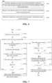
- FIG. 6 shows a schematic flowchart of an electrode plate inspection method 600 according to an embodiment of the present application.
- the electrode plate inspection method 600 may also include the following steps: In step S610, a separator 101 is combined on a side of a first electrode plate 102 in a thickness direction of the first electrode plate 102, the first electrode plate 102 including at least two sub-electrode plates arranged at intervals in a conveying direction of the first electrode plate 102.
- step S620 a first distance between two adjacent combined sub-electrode plates in the conveying direction is measured.
- step S630 whether the combined first electrode plate 102 is qualified is determined according to the first distance.
- the electrode plate inspection method 600 may further include: obtaining positions of the combined sub-electrode plates.
- the step of determining whether the combined first electrode plate 102 is qualified according to the first distance includes: determining whether the combined first electrode plate 102 is qualified according to the positions and the first distance.
- a color mark 1211 is provided at an end of each sub-electrode plate, and the step of obtaining positions of the combined sub-electrode plates includes: sensing the color marks 1211 to obtain the positions of the sub-electrode plates.
- the sub-electrode plates include a first sub-electrode plate 1021 and a second sub-electrode plate 1022 adjacent to each other, the second sub-electrode plate 1022 is located downstream of the first sub-electrode plate 1021 in the conveying direction, and the first distance is a distance between the first sub-electrode plate 1021 and the second sub-electrode plate 1022; and the step of obtaining positions of the combined sub-electrode plates includes: sensing a color between the first sub-electrode plate 1021 and a preset position to obtain the position of the second sub-electrode plate 1022, the preset position being a preset position of the combined second sub-electrode plate 1022.
- the step S630 may specifically include: determining whether the combined first electrode plate 102 is qualified according to the first distance and the sensed color.
- the step of determining whether the combined first electrode plate 102 is qualified according to the first distance and the sensed color includes: determining whether the combined first electrode plate 102 is qualified according to the first distance when the sensed color is the same as the color of the separator 101.
- the electrode plate inspection method 600 may further include: detecting a moving speed of the first electrode plate 102 in the conveying direction; and measuring the time it takes for the second sub-electrode plate 1022 to be conveyed to the preset position.
- the step of sensing a color between the first sub-electrode plate 1021 and a preset position includes: sensing, after it is determined that the second sub-electrode plate 1022 reaches the preset position according to the moving speed and the time, the color between the first sub-electrode plate 1021 and the preset position.
- the step S630 may specifically include: determining whether the combined first electrode plate 102 is qualified according to a deviation between the first distance and a predetermined distance.
- the electrode plate inspection method 600 may further include: combining a continuous sub-electrode plate 1023 with the separator 101, the first electrode plate 102 including the continuous sub-electrode plate 1023, and the continuous sub-electrode plate 1023 being a continuous electrode plate combined after the at least two sub-electrode plates.
- the electrode plate inspection method 600 may further include: removing, when the combined first electrode plate 102 is unqualified, the combined first electrode plate 102.
- the electrode plate inspection method 600 shown in Fig. 6 may be executed by the electrode plate inspection device 100 in the above embodiments.
- the electrode plate inspection method 600 can achieve the same technical effect as the electrode plate inspection device 100 described above, and will not be described in detail here for the sake of content detection.
- a first electrode plate 102 in Fig. 7 includes five sub-electrode plates.
- Fig. 7 will be described by taking the conveying of the second sub-electrode plate as an example.
- step S701 a winding device starts automatically, and a control unit receives an external start button signal.
- step S702 the control unit sends a conveying command to a first electrode plate unwinding driving roller and a separator unwinding driving roller, the conveying command being configured to instruct the first electrode plate unwinding driving roller and the separator unwinding driving roller to convey the first electrode plate 102 and the separator 101, respectively.
- step S703 the first electrode plate unwinding driving roller starts to rotate after receiving the conveying command.
- step S704 the first electrode plate 102 is moved by a fixed length according to a determined length of each sub-electrode plate included in the first electrode plate.
- step S705 after the first electrode plate 102 is moved by the fixed length, the first electrode plate 102 is cut off to obtain a second sub-electrode plate.
- step S706 the first electrode plate unwinding driving roller and the separator unwinding driving roller synchronously convey the second sub-electrode plate and the separator 101, and the combining unit combines the second sub-electrode plate with the separator 101.
- step S707 after estimating that the second sub-electrode plate reaches a preset position of the second sub-electrode plate, an encoder sends a detection command to a color mark sensor, the detection command being configured to instruct the color mark sensor to start sensing a color between the preset position of the second sub-electrode plate and the first sub-electrode plate.
- step S708 is executed. If the color between the preset position of the second sub-electrode plate and the first sub-electrode plate is the same as the color of the separator, it is indicated that the actual position of the second sub-electrode plate is the same as the preset position, and step S708 is executed. If the color between the preset position of the second sub-electrode plate and the first sub-electrode plate is the same as the color of the separator, it is indicated that the actual position of the second sub-electrode plate is different from the preset position, and the second sub-electrode plate is not qualified.
- the removing unit 170 removes the first sub-electrode plate and the second sub-electrode plate that have been combined, and step S703 is re-executed.
- a measuring unit 120 measures a first distance L between the first sub-electrode plate and the second sub-electrode plate that have been combined in the conveying direction.
- step S709 the first distance L is compared with a predetermined distance L1.
- step S710 is executed. If the deviation between L and L1 is not within the preset range, the removing unit 170 removes the first sub-electrode plate and the second sub-electrode plate that have been combined, and step S703 is re-executed.
- step S710 after the first electrode plate 102 is moved by the fixed length again, the first electrode plate 102 is cut off to obtain a third sub-electrode plate, and the combining unit combines the third sub-electrode plate with the separator.
- step S711 after estimating that the third sub-electrode plate reaches a preset position of the third sub-electrode plate, the encoder sends a detection command to the color mark sensor, the detection command being configured to instruct the color mark sensor to start sensing a color between the preset position of the third sub-electrode plate and the second sub-electrode plate.
- step S712 If the color between the preset position of the third sub-electrode plate and the second sub-electrode plate is the same as the color of the separator, it can be indicated that the actual position of the third sub-electrode plate is the same as the preset position, and step S712 is executed. If the color between the preset position of the third sub-electrode plate and the second sub-electrode plate is the same as the color of the separator, it is indicated that the actual position of the third sub-electrode plate is different from the preset position, and the third sub-electrode plate is not qualified.
- the removing unit 170 removes the first sub-electrode plate, the second sub-electrode plate and the third sub-electrode plate that have been combined, and step S703 is re-executed.
- a measuring unit 120 measures a first distance L + X1 between the third sub-electrode plate and the second sub-electrode plate that have been combined in the conveying direction.
- step S713 the first distance L + X1 is compared with a predetermined distance L2.
- step S714 is executed. If the deviation between L + X1 and + L2 is within a preset range, step S714 is executed. If the deviation between L + X1 and L2 is not within the preset range, the removing unit 170 removes the first sub-electrode plate, the second sub-electrode plate and the third sub-electrode plate that have been combined, and step S703 is re-executed.
- step S714 the same method is used to perform combination on a fourth sub-electrode plate and a fifth sub-electrode plate respectively.
- step S715 the first distance L + X3 between the fifth sub-electrode plate and the fourth sub-electrode plate is compared with a predetermined distance L4.
- step S716 is executed. If the deviation between L + X3 and L4 is within a preset range, step S716 is executed. If the deviation between L + X3 and L4 is not within the preset range, the removing unit 170 removes the first sub-electrode plate, the second sub-electrode plate, the third sub-electrode plate, the fourth sub-electrode plate and the fifth sub-electrode plate that have been combined, and step S703 is re-executed.
- step S716 the combined first electrode plate is wound together until a complete wound electrode assembly as shown in Fig. 3 is formed.
- L L1 in Fig. 7 does not mean that L is absolutely equal to L1, but rather that the deviation between L and L1 is within a preset range.
Landscapes
- Chemical & Material Sciences (AREA)
- Engineering & Computer Science (AREA)
- Manufacturing & Machinery (AREA)
- Chemical Kinetics & Catalysis (AREA)
- Electrochemistry (AREA)
- General Chemical & Material Sciences (AREA)
- Physics & Mathematics (AREA)
- General Physics & Mathematics (AREA)
- Spectroscopy & Molecular Physics (AREA)
- Health & Medical Sciences (AREA)
- Life Sciences & Earth Sciences (AREA)
- Analytical Chemistry (AREA)
- Biochemistry (AREA)
- General Health & Medical Sciences (AREA)
- Immunology (AREA)
- Pathology (AREA)
- Secondary Cells (AREA)
- Controlling Rewinding, Feeding, Winding, Or Abnormalities Of Webs (AREA)
- Controlling Sheets Or Webs (AREA)
Abstract
Description
- The present application claims the priority of
Chinese Application No. 202210489180.9 entitled "ELECTRODE PLATE INSPECTION DEVICE AND METHOD, AND WINDING DEVICE" and filed with the China National Intellectual Property Administration on 07 May, 2022 - The present application relates to the field of inspection technology, and in particular to an electrode plate inspection device and method, and a winding device.
- Energy conservation and emission reduction are the key to the sustainable development of the automobile industry. In this case, electric vehicles have become an important part of the sustainable development of the automobile industry because of their advantages of energy saving and environmental friendliness. For the electric vehicles, the battery technology is an important factor related to their development.
- The battery refers to a physical module that includes one or more battery cells to supply electric energy. The battery cell includes an electrode assembly composed of electrode plates and a separator. The quality of the electrode plate is closely related to the quality of the battery. Therefore, how to effectively inspect the electrode plate is an urgent problem to be solved.
- Embodiments of the present application provide an electrode plate inspection device and method, and a winding device, which can enable effective inspection of an electrode plate, thereby improving the quality of the electrode plate.
- In a first aspect, provided is an electrode plate inspection device, including: a combining unit is configured to combine a separator on a side of a first electrode plate in a thickness direction of the first electrode plate, the first electrode plate including at least two sub-electrode plates arranged at intervals in a conveying direction of the first electrode plate; a measuring unit arranged downstream of the combining unit in the conveying direction, and configured to measure a first distance between two adjacent combined sub-electrode plates in the conveying direction; and a processing unit configured to determine whether the combined first electrode plate is qualified according to the first distance.
- In the embodiments of the present application, at least two electrode plates are arranged at intervals, and the distance between two adjacent electrode plates affects the quality of the battery. For example, if the electrode plate is subsequently subjected to a winding operation and the distance between two adjacent electrode plates is not appropriate, a corner of the electrode plate may be wrinkled, thereby seriously affecting the energy density, service life and other performances of the battery. Therefore, determining whether an electrode plate is qualified according to the distance between two adjacent electrode plates can enable effective inspection of the electrode plate, improving the quality of the electrode plate, thereby improving the performance of the battery composed of this electrode plate.
- Further, the separator includes a first separator and a second separator, and the electrode plate and the separator are combined in advance, so that the problem of misalignment between the first separator and the second separator during subsequent operations can be reduced, and the quality of the electrode plate can thus be further improved.
- In some possible embodiments, the measuring unit further includes a sensor configured to obtain positions of the combined sub-electrode plates; and the processing unit is configured to determine whether the combined first electrode plate is qualified according to the positions and the first distance.
- In the above technical solution, a sensor configured to obtain positions of the combined sub-electrode plates is added in the electrode plate inspection device, and whether the first electrode plate is qualified is determined according to the positions of the combined sub-electrode plates in addition to the first distance. That is, whether the first electrode plate is qualified is determined according to multiple parameters, so that the inspection accuracy of the electrode plate can be improved, further improving the quality of the electrode plate and the battery composed of this electrode plate.
- In some possible embodiments, the sensor is a color mark sensor, a color mark is provided at an end of each sub-electrode plate, and the color mark sensor is configured to obtain the positions of the sub-electrode plates by sensing the color marks.
- In the above technical solution, since a color mark is provided at an end of each sub-electrode plate, and the color mark sensor obtains the positions of the sub-electrode plates by sensing the color marks, the positions of the sub-electrode plates can be determined with a high accuracy. In addition, the sensor, which is configured as a color mark sensor, is less costly.
- In some possible embodiments, the sub-electrode plates include a first sub-electrode plate and a second sub-electrode plate adjacent to each other, the second sub-electrode plate is located downstream of the first sub-electrode plate in the conveying direction, and the first distance is a distance between the first sub-electrode plate and the second sub-electrode plate; wherein the sensor is a color mark sensor configured to obtain the position of the second sub-electrode plate by sensing a color between the first sub-electrode plate and a preset position, the preset position being a preset position of the combined second sub-electrode plate; and the processing unit is configured to determine whether the combined first electrode plate is qualified according to the first distance and the color sensed by the color mark sensor.
- In the above technical solution, it is simple for the processing unit to implement the determination of whether the first electrode plate is qualified according to the first distance and the color sensed by the color mark sensor; and compared with determining whether the first electrode plate is qualified according to one parameter (i.e., the first distance), determining whether the first electrode plate is qualified according to multiple parameters (i.e., the first distance and the color sensed by the color mark sensor) can improve the accuracy of determining whether the first electrode plate is qualified to some extent, further improving the quality of the electrode plate and the battery composed of this electrode plate. In addition, the sensor, which is configured as a color mark sensor, is less costly.
- In some possible embodiments, the processing unit is configured to determine whether the combined first electrode plate is qualified according to the first distance when the color sensed by the color mark sensor is the same as the color of the separator.
- In the above technical solution, if the color sensed by the color mark sensor is the same as the color of the separator, it is indicated that the position of the first sub-electrode plate is the same as the preset position, that is, the absolute position of the first sub-electrode plate is accurate. In this case, determining whether the combined first electrode plate is qualified according to the first distance contributes to further improving the inspection accuracy of the electrode plate.
- In some possible embodiments, further included are: a speed sensor configured to detect a moving speed of the first electrode plate in the conveying direction; and a timer configured to measure the time it takes for the second sub-electrode plate to be conveyed to the preset position; wherein after it is determined that the second sub-electrode plate reaches the preset position according to the moving speed and the time, the color mark sensor is configured to sense the color between the first sub-electrode plate and the preset position.
- In the above technical solution, whether the second sub-electrode plate reaches the preset position is determined by means of the speed sensor and the timer, so that the accuracy of determining whether the second sub-electrode plate reaches the preset position is high, and the color mark sensor can start sensing the color between the first sub-electrode plate and the preset position at an accurate time, thereby further improving the inspection accuracy of the electrode plate.
- In some possible embodiments, the processing unit is configured to determine whether the combined first electrode plate is qualified according to a deviation between the first distance and a predetermined distance.
- In some possible embodiments, when the combined first electrode plate is qualified, the combining unit is further configured to combine a continuous sub-electrode plate with the separator, the first electrode plate including the continuous sub-electrode plate, and the continuous sub-electrode plate being a continuous electrode plate combined after the at least two sub-electrode plates.
- Since the angle of an outer corner is small when the electrode plate is subjected to a winding operation, the wrinkles caused by winding the electrode plate around the corner are relatively slight. In addition to the sub-electrode plates arranged at intervals, the first electrode plate in the above technical solution further includes a continuous sub-electrode plate, which can improve the performance of the battery, for example, increasing the energy density of the battery.
- In some possible embodiments, further included is a removing unit configured, when the combined first electrode plate is unqualified, to remove the combined first electrode plate.
- In the above technical solution, when the combined first electrode plate is unqualified, the removal of the unqualified first electrode plate can significantly increase the removal rate of unqualified products and thus improve the product quality of the battery.
- In a second aspect, provided is a winding device, including: an electrode plate inspection device in the first aspect or in its various embodiments; and a winding needle configured to wind the combined first electrode plate and a second electrode plate together, wherein the second electrode plate is arranged on a side of the separator facing away from the first electrode plate, and the first electrode plate and the second electrode plate have different polarities.
- In some possible embodiments, the combining unit is further configured to combine the second electrode plate with the separator, and the second electrode plate is a continuous electrode plate and is combined on the side of the separator facing away from the first electrode plate.
- In a third aspect, provided is an electrode plate inspection method, including: combining a separator on a side of a first electrode plate in a thickness direction of the first electrode plate, the first electrode plate including at least two sub-electrode plates arranged at intervals in a conveying direction of the first electrode plate; measuring a first distance between two adjacent combined sub-electrode plates in the conveying direction; and determining whether the combined first electrode plate is qualified according to the first distance.
- In some possible embodiments, the electrode plate inspection method further includes: obtaining positions of the combined sub-electrode plates; wherein the step of determining whether the combined first electrode plate is qualified according to the first distance includes: determining whether the combined first electrode plate is qualified according to the positions and the first distance.
- In some possible embodiments, a color mark is provided at an end of each sub-electrode plate, and the step of obtaining positions of the combined sub-electrode plates includes: sensing the color marks to obtain the positions of the sub-electrode plates.
- In some possible embodiments, the sub-electrode plates include a first sub-electrode plate and a second sub-electrode plate adjacent to each other, the second sub-electrode plate is located downstream of the first sub-electrode plate in the conveying direction, and the first distance is a distance between the first sub-electrode plate and the second sub-electrode plate; the step of obtaining positions of the combined sub-electrode plates includes: sensing a color between the first sub-electrode plate and a preset position to obtain the position of the second sub-electrode plate, the preset position being a preset position of the combined second sub-electrode plate; and the step of determining whether the combined first electrode plate is qualified according to the first distance and the positions includes: determining whether the combined first electrode plate is qualified according to the first distance and the sensed color.
- In some possible embodiments, the step of determining whether the combined first electrode plate is qualified according to the first distance and the sensed color includes: determining whether the combined first electrode plate is qualified according to the first distance when the sensed color is the same as the color of the separator.
- In some possible embodiments, the electrode plate inspection method further includes: detecting a moving speed of the first electrode plate in the conveying direction; and measuring the time it takes for the second sub-electrode plate to be conveyed to the preset position; wherein the step of sensing a color between the first sub-electrode plate and a preset position includes: sensing, after it is determined that the second sub-electrode plate reaches the preset position according to the moving speed and the time, the color between the first sub-electrode plate and the preset position.
- In some possible embodiments, the step of determining whether the combined first electrode plate is qualified according to the first distance includes: determining whether the combined first electrode plate is qualified according to a deviation between the first distance and a predetermined distance.
- In some possible embodiments, when the combined first electrode plate is qualified, the electrode plate inspection method further includes: combining a continuous sub-electrode plate with the separator, the first electrode plate including the continuous sub-electrode plate, and the continuous sub-electrode plate being a continuous electrode plate combined after the at least two sub-electrode plates.
- In some possible embodiments, the electrode plate inspection method further includes: removing, when the combined first electrode plate is unqualified, the combined first electrode plate.
- In order to more clearly illustrate the technical solutions of the embodiments of the present application, the drawings to be used in the description of the embodiments of the present application will be described briefly below. Obviously, the drawings in the following description are merely some embodiments of the present application. For those skilled in the art, other drawings can also be obtained according to these drawings without any creative effort.
-
Fig. 1 is a schematic diagram of an electrode plate inspection device according to an embodiment of the present application. -
Fig. 2 is a schematic diagram of an electrode assembly according to an embodiment of the present application. -
Fig. 3 is a schematic diagram of another electrode plate inspection device according to an embodiment of the present application. -
Fig. 4 is a schematic diagram of a first electrode plate combined with a separator according to an embodiment of the present application. -
Fig. 5 is a schematic diagram of a winding device according to an embodiment of the present application. -
Fig. 6 is a schematic block diagram of an electrode plate inspection method according to an embodiment of the present application. -
Fig. 7 is a flow chart of a possible embodiment of an electrode plate inspection method according to an embodiment of the present application. - In the accompanying drawings, the figures are not necessarily drawn to scale.
- Implementations of the present application are described in further detail below in conjunction with the drawings and embodiments. The following detailed description of the embodiments and the drawings are configured to illustrate the principles of the present application by way of example, but should not be configured to limit the scope of the present application, that is, the present application is not limited to the described embodiments.
- In the description of the present application, it should be noted that, unless otherwise stated, "plurality of" means two or more; the orientation or positional relationships indicated by the terms "upper", "lower", "left", "right", "inner" and "outer" are only for facilitating the description of the present application and simplifying the description, rather than indicating or implying that the apparatus or element referred to must have a particular orientation or be constructed and operated in a particular orientation, and therefore will not be interpreted as limiting the present application. In addition, the terms "first", "second" and "third" are used for descriptive purposes only, and cannot be construed as indicating or implying relative importance. "Perpendicular" is not strictly perpendicular, but within the allowable range of errors. "Parallel" is not strictly parallel, but within the allowable range of errors.
- Orientation words appearing in the following description are all directions shown in the drawings, and do not limit the specific structure of the present application. In the description of the present application, it should also be noted that, unless otherwise expressly specified and limited, the terms "mount," "connected," and "connecting" should be broadly understood, for example, they may be a fixed connection or a detachable connection or be an integrated connection; or may be a direct connection or an indirect connection through an intermediate medium. For those of ordinary skill in the art, the specific meanings of the above terms in the present application may be understood according to specific circumstances.
- Unless otherwise defined, all technical and scientific terms used in the present application have the same meanings as those commonly understood by those skilled in the art to which the present application belongs. The terms used in the specification of the present application are merely for the purpose of describing specific embodiments, but are not intended to limit the present application. The terms "comprising" and "having" and any variations thereof in the specification and the claims of the present application as well as the foregoing description of the drawings are intended to cover non-exclusive inclusions. The terms "first", "second", etc. in the specification and the claims of the present application as well as the above drawings are used to distinguish different objects, rather than to describe a specific order or primary-secondary relationship.
- The phrase "embodiment" referred to in the present application means that the descriptions of specific features, structures, and characteristics in combination with the embodiment are included in at least one embodiment of the present application. The appearance of this phrase in various places in the specification does not necessarily refer to the same embodiment, nor is it a separate or alternative embodiment that is mutually exclusive with other embodiments. It is understood explicitly and implicitly by those skilled in the art that the embodiments described in the present application can be combined with other embodiments.
- In the vehicle industry environment that uses traditional energy as power supply, environmental pollution problems are becoming more and more serious. Actively developing new energy vehicles can reduce harm to the environment. For the new energy vehicles, the battery technology is an important factor related to their development.
- The battery refers to a physical module that includes one or more battery cells to supply electric energy. For example, the battery mentioned in the present application may include a battery module or a battery pack, etc. The battery generally includes a box for packaging one or more battery cells. The box can reduce the influence of liquid or other foreign matters on the charging or discharging of the battery cells.
- Optionally, the battery cell may include a lithium-ion secondary battery, a lithium-ion primary battery, a lithium sulfur battery, a sodium lithium-ion battery, a sodium-ion battery or a magnesium-ion battery and so on, which will not be limited in the embodiments of the present application. In some embodiments, a battery cell may also be called a battery core.
- The battery cell includes an electrode assembly and an electrolyte solution, the electrode assembly being composed of a positive electrode plate, a negative electrode plate and a separator. The battery cell operates mainly relying on the movement of metal ions between the positive electrode plate and the negative electrode plate. The positive electrode plate includes a positive electrode current collector and a positive electrode active material layer, a surface of the positive electrode current collector is coated with the positive electrode active material layer, the positive electrode current collector not coated with the positive electrode active material layer protrudes from the positive electrode current collector already coated with the positive electrode active material layer, and the positive electrode current collector not coated with the positive electrode active material layer is used as a positive tab. Taking a lithium-ion battery as an example, the material of the positive electrode current collector may be aluminum, and the positive electrode active material may be lithium cobalt oxide, lithium iron phosphate, ternary lithium, lithium manganate, etc. The negative electrode plate includes a negative electrode current collector and a negative electrode active material layer, a surface of the negative electrode current collector is coated with the negative electrode active material layer, the negative electrode current collector not coated with the negative electrode active material layer protrudes from the negative electrode current collector already coated with the negative electrode active material layer, and the negative electrode current collector not coated with the negative electrode active material layer is used as a negative tab. The material of the negative electrode current collector may be copper, and the negative electrode active material may be carbon, silicon, etc. In order to allow a large current to pass without causing fusing, there are a plurality of positive tabs which are stacked together, and there are a plurality of negative tabs which are stacked together. The separator may be polypropylene (PP), polyethylene (PE), etc.
- At present, consumers have increasingly higher requirements for the performance of the battery, and the quality of the electrode plate is closely related to the performance of the battery. In view of this, an embodiment of the present application proposes an electrode plate inspection device, which can enable effective inspection of an electrode plate, improve the quality of the electrode plate, and further improve the performance of the battery.
-
Figs. 1 and 2 are schematic diagrams of an electrodeplate inspection device 100 according to an embodiment of the present application. As shown inFigs. 1 and 2 , the electrodeplate inspection device 100 may include a combiningunit 110, a measuringunit 120 and aprocessing unit 130. - The combining
unit 110 is configured to combine aseparator 101 on a side of afirst electrode plate 102 in a thickness direction of thefirst electrode plate 102. Thefirst electrode plate 102 includes at least two sub-electrode plates arranged at intervals in a conveying direction of thefirst electrode plate 102. The measuringunit 120 is arranged downstream of the combiningunit 110 in the conveying direction, and configured to measure a first distance between two adjacent combined sub-electrode plates in the conveying direction. Theprocessing unit 130 is configured to determine whether the combinedfirst electrode plate 102 is qualified according to the first distance. - In the embodiments of the present application, at least two electrode plates are arranged at intervals, and the distance between two adjacent electrode plates affects the quality of the battery. For example, if the electrode plate is subsequently subjected to a winding operation and the distance between two adjacent electrode plates is not appropriate, a corner of the electrode plate may be wrinkled, thereby seriously affecting the energy density, service life and other performances of the battery. Therefore, determining whether an electrode plate is qualified according to the distance between two adjacent electrode plates can enable effective inspection of the electrode plate, improving the quality of the electrode plate, thereby improving the performance of the battery composed of this electrode plate.
- Further, as shown in
Fig. 2 , theseparator 101 includes a first separator and a second separator, and the electrode plate and theseparator 101 are combined in advance, so that the problem of misalignment between the first separator and the second separator during subsequent operations can be reduced, and the quality of the electrode plate can thus be further improved. - Specifically, the combining
unit 110 may first combine theseparator 101 with the first sub-electrode plate of thefirst electrode plate 102. Afterwards, the combiningunit 120 combines theseparator 101 with the second sub-electrode plate, and the measuringunit 120 measures the first distance between the first sub-electrode plate and the second sub-electrode plate. If theprocessing unit 130 determines that thefirst electrode plate 102 is qualified according to the first distance between the first sub-electrode plate and the second sub-electrode plate, the combining unit continues to combine theseparator 101 with a third sub-electrode plate, and the measuringunit 120 measures a first distance between the second sub-electrode plate and the third sub-electrode plate, until all the sub-electrode plates included in thefirst electrode plate 102 are combined. - Alternatively, the combining
unit 110 may first combine all the sub-electrode plates included in thefirst electrode plate 102 with theseparator 101, the measuringunit 120 then measures at least one first distance between two adjacent combined sub-electrode plates, and theprocessing unit 130 determines whether the combinedfirst electrode plate 102 is qualified according to the at least one first distance. - Alternatively, the combining
unit 110 may combine N sub-electrode plates each time, where N is a positive integer greater than 1 and less than the number of sub-electrode plates included in thefirst electrode plate 102, and the measuringunit 120 then measures a first distance between the N sub-electrode plates once. - Optionally, the
first electrode plate 102 may include five or six sub-electrode plates. For example, as shown inFig. 3 , thefirst electrode plate 102 includes five sub-electrode plates. - When the combined
first electrode plate 102 is subjected to a winding operation, the five or six sub-electrode plates located at the beginning of the winding may have a corner wrinkled as shown inFig. 3 . Therefore, the number of sub-electrode plates included in thefirst electrode plate 102 is set to 5 or 6, so that when the combinedfirst electrode plate 102 is wound, the electrode plate can just avoid the corner, thereby further improving the quality of the electrode plate and the performance of the battery composed of this electrode plate. - Referring to
Figs. 3 and 4 , when thefirst electrode plate 102 is subjected to a winding operation, the corner at the beginning of the winding may become larger and larger. Therefore, in the conveying direction of thefirst electrode plate 102, the first distance between adjacent sub-electrode plates among the at least two sub-electrode plates gradually increases. For example, the first distance between the first sub-electrode plate and the second sub-electrode plate is L, the first distance between the second sub-electrode plate and the third sub-electrode plate is L + X1, and the first distance between the third sub-electrode plate and a fourth sub-electrode plate is L + X2. L, X1 and X2 are all positive integers, and X1 is greater than X2. - When the
first electrode plate 102 is subjected to a winding operation, the corner at the beginning of the winding may become larger and larger. Therefore, in the above technical solution, the first distance between adjacent sub-electrode plates among the at least two sub-electrode plates is also set to be larger and larger. That is, the first distance between adjacent sub-electrode plates matches the corner of the electrode assembly, so that thefirst electrode plate 102 can effectively avoid the corner position during the polarity winding operation of thefirst electrode plate 102, thereby improving the performance of the battery composed of thefirst electrode plate 102. - Optionally, the measuring
unit 120 may be an image measuring unit. The image measuring unit may be, for example, a charge-coupled device (CCD), a camera, etc. - The measuring
unit 120 may periodically measure the first distance. For example, the first distance is measured every 5 ms. Alternatively, the time interval at which themeasuring unit 120 measures the first distance each time may be different. For example, the time interval between the first measurement of the first distance by the measuringunit 120 and the second measurement of the first distance is 3 ms, and the time interval between the second measurement of the first distance and the third measurement of the first distance is 5 ms. - In some embodiments, in order to further reduce the problem of wrinkling at the corner of the electrode plate, still referring to
Fig. 2 , the measuringunit 120 may further include asensor 121 configured to obtain positions of the combined sub-electrode plates. Theprocessing unit 130 is configured to determine whether the combinedfirst electrode plate 102 is qualified according to the positions of the sub-electrode plates and the first distance. - In the above technical solution, a sensor configured to obtain positions of the combined sub-electrode plates is added in the electrode plate inspection device, and whether the
first electrode plate 102 is qualified is determined according to the positions of the combined sub-electrode plates in addition to the first distance. That is, whether thefirst electrode plate 102 is qualified is determined according to multiple parameters, so that the inspection accuracy of the electrode plate can be improved, further improving the performance of the electrode plate and the battery composed of this electrode plate. - It should be noted that, in
Fig. 2 , the measuring unit configured to measure the first distance between the two adjacent sub-electrode plates in the conveying direction may be acamera 122. That is, the measuringunit 120 may include asensor 121 and acamera 122. - In some embodiments, the
sensor 121 may be a color mark sensor. As shown inFig. 4 , acolor mark 1211 is provided at an end of each sub-electrode plate, and the color mark sensor may be configured to obtain the positions of the sub-electrode plates by means of the color marks 1211. - The
color mark 1211 provided at the end of each sub-electrode plate is not specifically limited in the embodiments of the present application. Thecolor mark 1211 can be any color, such as red, yellow, etc. The color marks 1211 provided at the ends of different sub-electrode plates may be the same or different. For example, thecolor mark 1211 provided at the end of the first sub-electrode plate is red, and thecolor mark 1211 provided at the end of the second sub-electrode plate is yellow. - Optionally, a
color mark 1211 may be provided at either end of each sub-electrode plate, orcolor marks 1211 may be provided at two ends of each sub-electrode plate. - In this technical solution, since a
color mark 1211 is provided at an end of each sub-electrode plate, and the color mark sensor obtains the positions of the sub-electrode plates by sensing the color marks 1211, the positions of the sub-electrode plates can be determined with a high accuracy. In addition, the sensor, which is configured as a color mark sensor, is less costly. - In some embodiments, as shown in
Figure 4 , the sub-electrode plates may include a firstsub-electrode plate 1021 and a secondsub-electrode plate 1022 adjacent to each other, the secondsub-electrode plate 1022 is located downstream of the firstsub-electrode plate 1021 in the conveying direction, and the first distance is a distance between the firstsub-electrode plate 1021 and the secondsub-electrode plate 1022. The color mark sensor may be configured to obtain the position of the second sub-electrode plate by sensing a color between the firstsub-electrode plate 1021 and a preset position, the preset position being a preset position of the combined secondsub-electrode plate 1022. Theprocessing unit 130 is configured to determine whether the combinedfirst electrode plate 102 is qualified according to the first distance and the color sensed by the color mark sensor. - As shown in
Fig. 4 , the color mark sensor may emit a signal, such as a pulse signal, toward a position (the position shown by the dotted line in the figure) slightly forward of the preset position in the direction of the firstsub-electrode plate 1021 to sense the color between the firstsub-electrode plate 1021 and the preset position. - Specifically, if the color sensed by the color mark sensor is the same as the color of the
separator 101, it is indicated that the position of the secondsub-electrode plate 1022 is the same as the preset position, and the position of the secondsub-electrode plate 1022 is qualified. If the color sensed by the color mark sensor is different from the color of theseparator 101, that is, the color sensed by the color mark sensor is the same as the color of the secondsub-electrode plate 1022, it means that the secondsub-electrode plate 1022 is different from the preset position, the position of the secondsub-electrode plate 1022 exceeds the preset position, and the position of the secondsub-electrode plate 1022 is unqualified. - In the above technical solution, it is simple for the processing unit to implement the determination of whether the
first electrode plate 102 is qualified according to the first distance and the color sensed by the color mark sensor; and the accuracy of determining whether thefirst electrode plate 102 is qualified can be improved to some extent, improving the quality of the electrode plate and the battery composed of this electrode plate. In addition, the sensor, which is configured as a color mark sensor, is less costly. - As an example, the
processing unit 130 may first determine the position of the secondsub-electrode plate 1022 according to the color sensed by the color mark sensor. When the color sensed by the color mark sensor is the same as the color of theseparator 101, theprocessing unit 130 may determine whether the combinedfirst electrode plate 102 is qualified according to the first distance again. - In the above technical solution, if the color sensed by the color mark sensor is the same as the color of the
separator 101, it is indicated that the position of the secondsub-electrode plate 1022 is the same as the preset position, that is, the absolute position of the secondsub-electrode plate 1022 is accurate. In this case, determining whether the combinedfirst electrode plate 102 is qualified according to the first distance contributes to further improving the inspection accuracy of the electrode plate. - As another example, the
processing unit 130 may first determine whether the combinedfirst electrode plate 102 is qualified according to the first distance. If it is determined that the combinedfirst electrode plate 102 is qualified according to the first distance, theprocessing unit 130 can further verify whether the combinedfirst electrode plate 102 is qualified according to the color sensed by the color mark sensor. If the color sensed by the color mark sensor is the same as the color of theseparator 101, it can be finally determined that thefirst electrode plate 102 is qualified. - In some embodiments, as shown again in
Fig. 2 , the electrodeplate inspection device 100 may further include aspeed sensor 150 and atimer 160. Thespeed sensor 150 is configured to detect a moving speed of thefirst electrode plate 102 in the conveying direction, and thetimer 160 is configured to measure the time it takes for the secondsub-electrode plate 1022 to be conveyed to the preset position. After it is determined that the secondsub-electrode plate 1022 reaches the preset position according to the moving speed and the time measured by thetimer 160, the color mark sensor is configured to sense the color between the firstsub-electrode plate 1021 and the preset position. - That is to say, after the
speed sensor 150 and thetimer 160 detect that the secondsub-electrode plate 1022 reaches the preset position, thespeed sensor 150 and/or thetimer 160 may send a detection command to the color mark sensor, the detection command being configured to instruct the color mark sensor to start sensing the color between the firstsub-electrode plate 1021 and the preset position. Alternatively, thespeed sensor 150 may send the moving speed of thefirst electrode plate 102 in the conveying direction to the color mark sensor, and thetimer 160 may send the time it takes for the secondsub-electrode plate 1022 to be conveyed to the preset position to the color mark sensor. Afterwards, the color mark sensor may determine whether the secondsub-electrode plate 1022 reaches the preset position. If the color mark sensor determines that the secondsub-electrode plate 1022 reaches the preset position, it starts to sense the color between the firstsub-electrode plate 1021 and the preset position. - Optionally, the
speed sensor 150 and thetimer 160 may be integrated in the same apparatus or device. For example, thespeed sensor 150 and thetimer 160 are both provided in an encoder. Alternatively, thespeed sensor 150 and thetimer 160 may be provided separately. - It should be understood that the
sensor 121 may be other sensors, such as a position sensor, in addition to the color mark sensor mentioned above. - In some embodiments of the present application, the
processing unit 130 may be specifically configured to determine whether the combinedfirst electrode plate 102 is qualified according to a deviation between the first distance and a predetermined distance. - The deviation mentioned in the above content may be, for example, a difference between the first distance and the predetermined distance, or may be a quotient between the first distance and the predetermined distance.
- Specifically, when the deviation between the first distance and the predetermined distance is within a preset range, the
processing unit 130 can determine that the combinedfirst electrode plate 102 is qualified; and when the deviation between the first distance and the predetermined distance is not within the preset range, theprocessing unit 130 can determine that the combinedfirst electrode plate 102 is unqualified. - Illustratively, when the deviation between the first distance and the predetermined distance is the difference, the preset range may be 0; and when the deviation between the first distance and the predetermined distance is the quotient, the preset range may be 1.
- In addition to including the at least two sub-electrode plates arranged at intervals, as shown again in
Fig. 3 , thefirst electrode plate 102 may further include a continuoussub-electrode plate 1023. The continuoussub-electrode plate 1023 is a continuous electrode plate combined after the at least two sub-electrode plates. - Specifically, if the
processing unit 130 determines that the combinedfirst electrode plate 102 is qualified, the combiningunit 110 may be further configured to combine the continuoussub-electrode plate 1023 with theseparator 101. - Since the angle of an outer corner is small when the electrode plate is subjected to a winding operation, the wrinkles caused by winding the electrode plate around the corner are relatively slight. In addition to the sub-electrode plates arranged at intervals, the
first electrode plate 102 in the above technical solution further includes a continuoussub-electrode plate 1023. The continuoussub-electrode plate 1023 can improve the performance of the battery, for example, increasing the energy density of the battery. - Further, as shown again in
Fig. 2 , the electrodeplate inspection device 100 may further include a removingunit 170 configured, when theprocessing unit 130 determines that the combinedfirst electrode plate 102 is unqualified, to remove the combinedfirst electrode plate 102. - The removing
unit 170 may be, for example, a cutter. When thefirst electrode plate 102 is unqualified, the cutter may cut off the currentfirst electrode plate 102 to remove thefirst electrode plate 102. - If a sub-electrode plate is combined by the combining
unit 110, the measuringunit 120 then measures a first distance, and theprocessing unit 130 determines that the combinedfirst electrode plate 102 is unqualified according to the first distance measured by the measuringunit 120, the removingunit 170 may remove the combinedfirst electrode plate 102 by only removing the most recently combined sub-electrode plate. If after the third sub-electrode plate is combined by the combiningunit 110, theprocessing unit 130 determines that thefirst electrode plate 102 is unqualified according to the first distance between the third sub-electrode plate and the second sub-electrode plate, the removingunit 170 may remove the third sub-electrode plate. Alternatively, the removingunit 170 may remove all the combined sub-electrode plates, such as the first sub-electrode plate, the second sub-electrode plate and the third sub-electrode plate. - If the combining
unit 110 combines all the sub-electrode plates with theseparator 101, the measuringunit 120 then measures the first distance between two adjacent sub-electrode plates, and theprocessing unit 130 determines the combinedfirst electrode plate 102 is unqualified according to the measured at least one first distance, the removingunit 170 may remove the combinedfirst electrode plate 102 by removing the entirefirst electrode plate 102. - After the removing
unit 170 removes the unqualifiedfirst electrode plate 102, the combiningunit 110 may combine the first sub-electrode plate with theseparator 101 again. - In the above technical solution, when the combined
first electrode plate 102 is unqualified, the removal of the unqualifiedfirst electrode plate 102 can significantly increase the removal rate of unqualified products and thus improve the product quality of the battery. - In addition to the electrode plate inspection device mentioned above, an embodiment of the present application also provides a winding device. As shown in
Fig. 5 , the windingdevice 500 may include an electrode plate inspection device 510 and a windingneedle 520. The electrode plate inspection device 510 may be the electrodeplate inspection device 100 in the above embodiments. - The winding
needle 520 may configured to wind the combinedfirst electrode plate 102 and asecond electrode plate 501 together. Thesecond electrode plate 501 is arranged on a side of theseparator 101 facing away from thefirst electrode plate 102, and thefirst electrode plate 102 and thesecond electrode plate 501 have different polarities. - Optionally, the
first electrode plate 102 may be a positive electrode plate, and thesecond electrode plate 501 may be a negative electrode plate. Configuring thefirst electrode plate 102 as a positive electrode plate and thesecond electrode plate 501 as a negative electrode plate can effectively reduce the problem of lithium plating. - It should be understood that the names of the negative electrode plate and the positive electrode plate are not specifically limited in the embodiments of the present application, that is, they may also be called other names. For example, the positive electrode plate may also be called the cathode electrode plate, and the negative electrode plate may also be called the anode electrode plate.
- Optionally, the combining
unit 110 may be further configured to combine thesecond electrode plate 501 and theseparator 101. Thesecond electrode plate 501 is a continuous electrode plate and is combined on the side of theseparator 101 away from thefirst electrode plate 102. - It should be understood that in the embodiments of the present application, the terms "first" and" second" are only intended to distinguish different objects, but do not limit the scope of the embodiments of the present application.
- Further, the winding
device 500 may further include heating units, which may be arranged on two sides of theseparator 101 to heat an adhesive on an upper surface and a lower surface of theseparator 101. By heating the adhesive, the viscosity of the adhesive is enhanced, contributing to the combining of theseparator 101 with thefirst electrode plate 102. - Illustratively, the heating unit may be, but is not limited to, an oven.
- As shown in
Fig. 5 , the windingdevice 500 may further include acutting unit 530. Thecutting unit 530 is arranged upstream of the combiningunit 110 in the conveying direction, and may be configured to cut the continuousfirst electrode plate 102 before the combiningunit 110 combines theseparator 101 with thefirst electrode plate 102 together, so as to cut thefirst electrode plate 102 into at least two sub-electrode plates arranged at intervals in the conveying direction. The lengths of the at least two cut sub-electrode plates are the same. - The winding
device 500 may further include a control unit, a first electrode plate unwinding driving roller and a separator unwinding driving roller. The control unit may be configured to send a conveying command to the first electrode plate unwinding driving roller and the separator unwinding driving roller after receiving a signal that the windingdevice 500 starts to operate, the conveying command being configured to instruct the first electrode plate unwinding driving roller to start conveying thefirst electrode plate 102 and the separator unwinding driving roller to start conveying theseparator 101. After receiving the conveying command, the first electrode plate unwinding driving roller and the separator unwinding driving roller start to rotate to convey thefirst electrode plate 102 and theseparator 101. This can facilitate subsequent operations, for example, facilitating the combiningunit 110 to combine theseparator 101 with thefirst electrode plate 102 together. - After the winding
device 500 performs a winding operation on thefirst electrode plate 102 and thesecond electrode plate 501, an electrode assembly as shown inFig. 3 can be obtained. As can be seen fromFig. 3 , the electrode assembly is a wound and stacked integrated electrode assembly. - The device embodiments of the present application are described above in detail with reference to
Figs. 1 to 4 , and a method embodiment of the present application will be described below in detail with reference toFig. 6 . It should be understood that the method embodiments and the device embodiments correspond to each other, and similar descriptions can refer to the device embodiments. -
FIG. 6 shows a schematic flowchart of an electrodeplate inspection method 600 according to an embodiment of the present application. As shown inFig. 6 , the electrodeplate inspection method 600 may also include the following steps:
In step S610, aseparator 101 is combined on a side of afirst electrode plate 102 in a thickness direction of thefirst electrode plate 102, thefirst electrode plate 102 including at least two sub-electrode plates arranged at intervals in a conveying direction of thefirst electrode plate 102. - In step S620, a first distance between two adjacent combined sub-electrode plates in the conveying direction is measured.
- In step S630, whether the combined
first electrode plate 102 is qualified is determined according to the first distance. - Optionally, in some embodiments, the electrode
plate inspection method 600 may further include: obtaining positions of the combined sub-electrode plates. The step of determining whether the combinedfirst electrode plate 102 is qualified according to the first distance includes: determining whether the combinedfirst electrode plate 102 is qualified according to the positions and the first distance. - Optionally, in some embodiments, a
color mark 1211 is provided at an end of each sub-electrode plate, and the step of obtaining positions of the combined sub-electrode plates includes: sensing the color marks 1211 to obtain the positions of the sub-electrode plates. - Optionally, in some embodiments, the sub-electrode plates include a first
sub-electrode plate 1021 and a secondsub-electrode plate 1022 adjacent to each other, the secondsub-electrode plate 1022 is located downstream of the firstsub-electrode plate 1021 in the conveying direction, and the first distance is a distance between the firstsub-electrode plate 1021 and the secondsub-electrode plate 1022; and the step of obtaining positions of the combined sub-electrode plates includes: sensing a color between the firstsub-electrode plate 1021 and a preset position to obtain the position of the secondsub-electrode plate 1022, the preset position being a preset position of the combined secondsub-electrode plate 1022. - The step S630 may specifically include: determining whether the combined
first electrode plate 102 is qualified according to the first distance and the sensed color. - Optionally, in some embodiments, the step of determining whether the combined
first electrode plate 102 is qualified according to the first distance and the sensed color includes: determining whether the combinedfirst electrode plate 102 is qualified according to the first distance when the sensed color is the same as the color of theseparator 101. - Optionally, in some embodiments, the electrode
plate inspection method 600 may further include: detecting a moving speed of thefirst electrode plate 102 in the conveying direction; and measuring the time it takes for the secondsub-electrode plate 1022 to be conveyed to the preset position. The step of sensing a color between the firstsub-electrode plate 1021 and a preset position includes: sensing, after it is determined that the secondsub-electrode plate 1022 reaches the preset position according to the moving speed and the time, the color between the firstsub-electrode plate 1021 and the preset position. - Optionally, in some embodiments, the step S630 may specifically include: determining whether the combined
first electrode plate 102 is qualified according to a deviation between the first distance and a predetermined distance. - Optionally, in some embodiments, when the combined
first electrode plate 102 is qualified, the electrodeplate inspection method 600 may further include: combining a continuoussub-electrode plate 1023 with theseparator 101, thefirst electrode plate 102 including the continuoussub-electrode plate 1023, and the continuoussub-electrode plate 1023 being a continuous electrode plate combined after the at least two sub-electrode plates. - Optionally, in some embodiments, the electrode
plate inspection method 600 may further include: removing, when the combinedfirst electrode plate 102 is unqualified, the combinedfirst electrode plate 102. - It should be understood that the electrode
plate inspection method 600 shown inFig. 6 may be executed by the electrodeplate inspection device 100 in the above embodiments. The electrodeplate inspection method 600 can achieve the same technical effect as the electrodeplate inspection device 100 described above, and will not be described in detail here for the sake of content detection. - It should also be understood that the steps or operations in
Fig. 6 are merely examples, and the embodiments of the present application may also perform other operations or variations of the various operations inFig. 6 . - In order to more clearly understand the electrode
plate inspection method 600, an electrode plate inspection method according to a possible embodiment of the present application is described below with reference toFig. 7 . Afirst electrode plate 102 inFig. 7 includes five sub-electrode plates. - It should be noted that, since the embodiment of the present application assumes that the position of a first sub-electrode plate is qualified after a
separator 101 is combined with the first sub-electrode plate,Fig. 7 will be described by taking the conveying of the second sub-electrode plate as an example. - In step S701, a winding device starts automatically, and a control unit receives an external start button signal.
- In step S702, the control unit sends a conveying command to a first electrode plate unwinding driving roller and a separator unwinding driving roller, the conveying command being configured to instruct the first electrode plate unwinding driving roller and the separator unwinding driving roller to convey the
first electrode plate 102 and theseparator 101, respectively. - In step S703, the first electrode plate unwinding driving roller starts to rotate after receiving the conveying command.
- In step S704, the
first electrode plate 102 is moved by a fixed length according to a determined length of each sub-electrode plate included in the first electrode plate. - In step S705, after the
first electrode plate 102 is moved by the fixed length, thefirst electrode plate 102 is cut off to obtain a second sub-electrode plate. - In step S706, the first electrode plate unwinding driving roller and the separator unwinding driving roller synchronously convey the second sub-electrode plate and the
separator 101, and the combining unit combines the second sub-electrode plate with theseparator 101. - In step S707, after estimating that the second sub-electrode plate reaches a preset position of the second sub-electrode plate, an encoder sends a detection command to a color mark sensor, the detection command being configured to instruct the color mark sensor to start sensing a color between the preset position of the second sub-electrode plate and the first sub-electrode plate.
- If the color between the preset position of the second sub-electrode plate and the first sub-electrode plate is the same as the color of the separator, it can be indicated that the actual position of the second sub-electrode plate is the same as the preset position, and step S708 is executed. If the color between the preset position of the second sub-electrode plate and the first sub-electrode plate is the same as the color of the separator, it is indicated that the actual position of the second sub-electrode plate is different from the preset position, and the second sub-electrode plate is not qualified. The removing
unit 170 removes the first sub-electrode plate and the second sub-electrode plate that have been combined, and step S703 is re-executed. - In step S708, a measuring
unit 120 measures a first distance L between the first sub-electrode plate and the second sub-electrode plate that have been combined in the conveying direction. - In step S709, the first distance L is compared with a predetermined distance L1.
- If the deviation between L and L1 is within a preset range, step S710 is executed. If the deviation between L and L1 is not within the preset range, the removing
unit 170 removes the first sub-electrode plate and the second sub-electrode plate that have been combined, and step S703 is re-executed. - In step S710, after the
first electrode plate 102 is moved by the fixed length again, thefirst electrode plate 102 is cut off to obtain a third sub-electrode plate, and the combining unit combines the third sub-electrode plate with the separator. - In step S711, after estimating that the third sub-electrode plate reaches a preset position of the third sub-electrode plate, the encoder sends a detection command to the color mark sensor, the detection command being configured to instruct the color mark sensor to start sensing a color between the preset position of the third sub-electrode plate and the second sub-electrode plate.
- If the color between the preset position of the third sub-electrode plate and the second sub-electrode plate is the same as the color of the separator, it can be indicated that the actual position of the third sub-electrode plate is the same as the preset position, and step S712 is executed. If the color between the preset position of the third sub-electrode plate and the second sub-electrode plate is the same as the color of the separator, it is indicated that the actual position of the third sub-electrode plate is different from the preset position, and the third sub-electrode plate is not qualified. The removing
unit 170 removes the first sub-electrode plate, the second sub-electrode plate and the third sub-electrode plate that have been combined, and step S703 is re-executed. - In step S712, a measuring
unit 120 measures a first distance L + X1 between the third sub-electrode plate and the second sub-electrode plate that have been combined in the conveying direction. - In step S713, the first distance L + X1 is compared with a predetermined distance L2.
- If the deviation between L + X1 and + L2 is within a preset range, step S714 is executed. If the deviation between L + X1 and L2 is not within the preset range, the removing
unit 170 removes the first sub-electrode plate, the second sub-electrode plate and the third sub-electrode plate that have been combined, and step S703 is re-executed. - In step S714, the same method is used to perform combination on a fourth sub-electrode plate and a fifth sub-electrode plate respectively.
- In step S715, the first distance L + X3 between the fifth sub-electrode plate and the fourth sub-electrode plate is compared with a predetermined distance L4.
- If the deviation between L + X3 and L4 is within a preset range, step S716 is executed. If the deviation between L + X3 and L4 is not within the preset range, the removing
unit 170 removes the first sub-electrode plate, the second sub-electrode plate, the third sub-electrode plate, the fourth sub-electrode plate and the fifth sub-electrode plate that have been combined, and step S703 is re-executed. - In step S716, the combined first electrode plate is wound together until a complete wound electrode assembly as shown in
Fig. 3 is formed. - It should be noted that L = L1 in
Fig. 7 does not mean that L is absolutely equal to L1, but rather that the deviation between L and L1 is within a preset range. The same applies to L + X1 = L2 and L + X3 = L4. - While the present application has been described with reference to the preferred embodiments, various modifications may be made and components therein may be replaced with equivalents without departing from the scope of the present application. In particular, the technical features mentioned in the various examples can be combined in any manner as long as there is no structural conflict. The present application is not limited to the specific embodiments disclosed herein, but rather includes all technical solutions falling within the scope of the claims.
Claims (20)
- An electrode plate inspection device, comprising:a combining unit (110) configured to combine a separator (101) on a side of a first electrode plate (102) in a thickness direction of the first electrode plate (102), the first electrode plate (102) comprising at least two sub-electrode plates arranged at intervals in a conveying direction of the first electrode plate (102);a measuring unit (120) arranged downstream of the combining unit (110) in the conveying direction, and configured to measure a first distance between two adjacent combined sub-electrode plates in the conveying direction; anda processing unit (130) configured to determine whether the combined first electrode plate (102) is qualified according to the first distance.
- The electrode plate inspection device according to claim 1, wherein the measuring unit (110) further comprises:a sensor (121) configured to obtain positions of the combined sub-electrode plates; andthe processing unit (130) is configured to determine whether the combined first electrode plate (102) is qualified according to the positions and the first distance.
- The electrode plate inspection device according to claim 2, wherein the sensor (121) is a color mark sensor, a color mark (1211) is provided at an end of each sub-electrode plate, and the color mark sensor is configured to obtain the positions of the sub-electrode plates by sensing the color marks (1211).
- The electrode plate inspection device according to claim 2, wherein the sub-electrode plates comprise a first sub-electrode plate (1021) and a second sub-electrode plate (1022) adjacent to each other, the second sub-electrode plate (1022) is located downstream of the first sub-electrode plate (1021) in the conveying direction, and the first distance is a distance between the first sub-electrode plate (1021) and the second sub-electrode plate (1022);wherein the sensor (130) is a color mark sensor configured to obtain the position of the second sub-electrode plate (1022) by sensing a color between the first sub-electrode plate (1021) and a preset position, the preset position being a preset position of the combined second sub-electrode plate (1022); andthe processing unit (130) is configured to determine whether the combined first electrode plate (102) is qualified according to the first distance and the color sensed by the color mark sensor.
- The electrode plate inspection device according to claim 4, wherein the processing unit (130) is configured to determine whether the combined first electrode plate (102) is qualified according to the first distance when the color sensed by the color mark sensor is the same as the color of the separator (101).
- The electrode plate inspection device according to claim 4 or 5, further comprising:a speed sensor (150) configured to detect a moving speed of the first electrode plate (102) in the conveying direction; anda timer (160) configured to measure the time it takes for the second sub-electrode plate (1022) to be conveyed to the preset position; whereinafter it is determined that the second sub-electrode plate (1022) reaches the preset position according to the moving speed and the time, the color mark sensor is configured to sense the color between the first sub-electrode plate (1021) and the preset position.
- The electrode plate inspection device according to any one of claims 1 to 6, wherein the processing unit (130) is configured to determine whether the combined first electrode plate (102) is qualified according to a deviation between the first distance and a predetermined distance.
- The electrode plate inspection device according to any one of claims 1 to 7, wherein when the combined first electrode plate (102) is qualified, the combining unit (110) is further configured to:
combine a continuous sub-electrode plate (1023) with the separator (101), the first electrode plate (102) comprising the continuous sub-electrode plate (1023), and the continuous sub-electrode plate (1023) being a continuous electrode plate combined after the at least two sub-electrode plates. - The electrode plate inspection device according to any one of claims 1 to 7, further comprising:
a removing unit (170) configured, when the combined first electrode plate (102) is unqualified, to remove the combined first electrode plate (102). - A winding device, comprising:the electrode plate inspection device (510) according to any one of claims 1 to 9; anda winding needle (520) configured to wind the combined first electrode plate (102) and a second electrode plate (501) together, wherein the second electrode plate (501) is arranged on a side of the separator (101) facing away from the first electrode plate (102), and the first electrode plate (102) and the second electrode plate (501) have different polarities.
- The winding device according to claim 10, wherein the combining unit (110) is further configured to combine the second electrode plate (501) with the separator (101), and the second electrode plate (501) is a continuous electrode plate and is combined on the side of the separator (101) facing away from the first electrode plate (102).
- An electrode plate inspection method, comprising:combining a separator (101) on a side of a first electrode plate (102) in a thickness direction of the first electrode plate (102), the first electrode plate (102) comprising at least two sub-electrode plates arranged at intervals in a conveying direction of the first electrode plate (102);measuring a first distance between two adjacent combined sub-electrode plates in the conveying direction; anddetermining whether the combined first electrode plate (102) is qualified according to the first distance.
- The electrode plate inspection method according to claim 12, further comprising:obtaining positions of the combined sub-electrode plates; whereinthe step of determining whether the combined first electrode plate (102) is qualified according to the first distance comprises:
determining whether the combined first electrode plate (102) is qualified according to the positions and the first distance. - The electrode plate inspection method according to claim 13, wherein a color mark (1211) is provided at an end of each sub-electrode plate, and the step of obtaining positions of the combined sub-electrode plates comprises:
sensing the color marks (1211) to obtain the positions of the sub-electrode plates. - The electrode plate inspection method according to claim 13, wherein the sub-electrode plates comprise a first sub-electrode plate (1021) and a second sub-electrode plate (1022) adjacent to each other, the second sub-electrode plate (1022) is located downstream of the first sub-electrode plate (1021) in the conveying direction, and the first distance is a distance between the first sub-electrode plate (1021) and the second sub-electrode plate (1022);
the step of obtaining positions of the combined sub-electrode plates comprises:sensing a color between the first sub-electrode plate (1021) and a preset position to obtain the position of the second sub-electrode plate (1022), the preset position being a preset position of the combined second sub-electrode plate (1022); andthe step of determining whether the combined first electrode plate (102) is qualified according to the first distance and the positions comprises:
determining whether the combined first electrode plate (102) is qualified according to the first distance and the sensed color. - The electrode plate inspection method according to claim 15, wherein the step of determining whether the combined first electrode plate (102) is qualified according to the first distance and the sensed color comprises:
determining whether the combined first electrode plate (102) is qualified according to the first distance when the sensed color is the same as the color of the separator (101). - The electrode plate inspection method according to claim 15 or 16, further comprising:detecting a moving speed of the first electrode plate (102) in the conveying direction; andmeasuring the time it takes for the second sub-electrode plate (1022) to be conveyed to the preset position; whereinthe step of sensing a color between the first sub-electrode plate (1021) and a preset position comprises:
sensing, after it is determined that the second sub-electrode plate (1022) reaches the preset position according to the moving speed and the time, the color between the first sub-electrode plate (1021) and the preset position. - The electrode plate inspection method according to any one of claims 12 to 17, wherein the step of determining whether the combined first electrode plate (102) is qualified according to the first distance comprises:
determining whether the combined first electrode plate (102) is qualified according to a deviation between the first distance and a predetermined distance. - The electrode plate inspection method according to any one of claims 12 to 18, wherein when the combined first electrode plate (102) is qualified, the electrode plate inspection method further comprises:
combining a continuous sub-electrode plate (1023) with the separator (101), the first electrode plate (102) comprising the continuous sub-electrode plate (1023), and the continuous sub-electrode plate (1023) being a continuous electrode plate combined after the at least two sub-electrode plates. - The electrode plate inspection method according to any one of claims 12 to 18, further comprising:
removing, when the combined first electrode plate (102) is unqualified, the combined first electrode plate (102).
Applications Claiming Priority (2)
| Application Number | Priority Date | Filing Date | Title |
|---|---|---|---|
| CN202210489180.9A CN117053746A (en) | 2022-05-07 | 2022-05-07 | Pole piece detection device, pole piece detection method and winding device |
| PCT/CN2023/090718 WO2023216881A1 (en) | 2022-05-07 | 2023-04-26 | Plate test device and method, and winding device |
Publications (2)
| Publication Number | Publication Date |
|---|---|
| EP4467922A1 true EP4467922A1 (en) | 2024-11-27 |
| EP4467922A4 EP4467922A4 (en) | 2025-05-21 |
Family
ID=88666843
Family Applications (1)
| Application Number | Title | Priority Date | Filing Date |
|---|---|---|---|
| EP23802655.3A Pending EP4467922A4 (en) | 2022-05-07 | 2023-04-26 | Plate test device and method, and winding device |
Country Status (5)
| Country | Link |
|---|---|
| US (1) | US20240429432A1 (en) |
| EP (1) | EP4467922A4 (en) |
| KR (1) | KR20240140152A (en) |
| CN (1) | CN117053746A (en) |
| WO (1) | WO2023216881A1 (en) |
Family Cites Families (10)
| Publication number | Priority date | Publication date | Assignee | Title |
|---|---|---|---|---|
| CN102881946B (en) * | 2011-07-15 | 2015-03-25 | 深圳市吉阳自动化科技有限公司 | Lithium ion battery cell winding method |
| KR20150086042A (en) * | 2014-01-17 | 2015-07-27 | 주식회사 엠플러스 | Secondary battery eloctrode detection method |
| KR102836630B1 (en) * | 2019-03-26 | 2025-07-21 | 주식회사 엘지에너지솔루션 | Manufacture method for electrode assembly and manufacture apparatus for the same |
| CN111933996A (en) * | 2020-08-03 | 2020-11-13 | 苏州凌威新能源科技有限公司 | Manufacturing method of lithium battery |
| WO2022060703A1 (en) * | 2020-09-18 | 2022-03-24 | Enovix Operations Inc. | Processes for delineating a population of electrode structures in a web using a|laser beam |
| CN213340470U (en) * | 2020-09-18 | 2021-06-01 | 江苏时代新能源科技有限公司 | Battery winding system |
| CN112652802B (en) * | 2020-12-30 | 2022-12-13 | 蜂巢能源科技有限公司 | Lamination device |
| CN113532335A (en) * | 2021-07-16 | 2021-10-22 | 合肥国轩高科动力能源有限公司 | CCD detection device and detection method for alignment degree of winding core of winding machine |
| CN113782819B (en) * | 2021-08-30 | 2022-08-16 | 广东利元亨智能装备股份有限公司 | Method for determining edge distance of winding core tab and method for correcting winding equipment |
| DE202022101348U1 (en) * | 2022-03-14 | 2022-04-14 | Guangzhou Supersonic Automation Technology Co. , Ltd. | Full-featured detection system for winding defects in pole piece manufacture |
-
2022
- 2022-05-07 CN CN202210489180.9A patent/CN117053746A/en active Pending
-
2023
- 2023-04-26 WO PCT/CN2023/090718 patent/WO2023216881A1/en not_active Ceased
- 2023-04-26 KR KR1020247028831A patent/KR20240140152A/en active Pending
- 2023-04-26 EP EP23802655.3A patent/EP4467922A4/en active Pending
-
2024
- 2024-09-03 US US18/823,143 patent/US20240429432A1/en active Pending
Also Published As
| Publication number | Publication date |
|---|---|
| US20240429432A1 (en) | 2024-12-26 |
| WO2023216881A1 (en) | 2023-11-16 |
| KR20240140152A (en) | 2024-09-24 |
| EP4467922A4 (en) | 2025-05-21 |
| CN117053746A (en) | 2023-11-14 |
Similar Documents
| Publication | Publication Date | Title |
|---|---|---|
| US20230335776A1 (en) | Strip defect repair device | |
| WO2023217040A1 (en) | Deviation correction apparatus and winding machine | |
| US20150037658A1 (en) | Stack type battery | |
| CN116982185B (en) | Lamination method and device for pole pieces and lamination machine | |
| US20140113063A1 (en) | Method of manufacturing battery electrode and apparatus | |
| CN216054795U (en) | Negative electrode, electrode assembly, battery cell, battery pack, and device including the same | |
| EP4195356A1 (en) | Three-electrode battery and energy storage system | |
| US20240421357A1 (en) | Method and device for correcting positions of tabs of electrode assembly | |
| US11841328B2 (en) | Method and device for testing electrode sheet | |
| CN215299338U (en) | Laminate type soft package lithium ion battery with built-in temperature sensor | |
| JP2010040318A (en) | Method and device for detecting ae signal generating part of secondary battery | |
| EP4729187A1 (en) | Electrode sheet inspection control system | |
| KR101789854B1 (en) | System for judging a skew fail in a secondary battery and method thereof | |
| US20240429432A1 (en) | Electrode plate inspection device and method, and winding device | |
| JP2014143164A (en) | Method and device for checking secondary battery | |
| WO2023197117A1 (en) | Measurement method and apparatus for tab | |
| KR100696811B1 (en) | Electrode roll winding method of secondary battery | |
| US20240047639A1 (en) | Measurement device and electrode plate production system | |
| US11913769B2 (en) | Tab inspection method and apparatus | |
| US20240061047A1 (en) | Device and method for detecting internal defect of battery cell by using tdr | |
| CN113839111B (en) | A lithium ion battery and a terminal device including the lithium ion battery | |
| KR20220010167A (en) | Electrode assembly manufacturing equipment and mauufacturing method of electrode assembly | |
| EP4386362A1 (en) | Detection method and detection apparatus for electrode sheet, and stacking system | |
| KR102964327B1 (en) | Apparatus and method capable of simultaneously measuring electrode length and meandering | |
| US20250046778A1 (en) | Method of manufacturing electricity storage device, recording device, and electricity storage device manufacturing apparatus |
Legal Events
| Date | Code | Title | Description |
|---|---|---|---|
| STAA | Information on the status of an ep patent application or granted ep patent |
Free format text: STATUS: THE INTERNATIONAL PUBLICATION HAS BEEN MADE |
|
| PUAI | Public reference made under article 153(3) epc to a published international application that has entered the european phase |
Free format text: ORIGINAL CODE: 0009012 |
|
| STAA | Information on the status of an ep patent application or granted ep patent |
Free format text: STATUS: REQUEST FOR EXAMINATION WAS MADE |
|
| 17P | Request for examination filed |
Effective date: 20240823 |
|
| AK | Designated contracting states |
Kind code of ref document: A1 Designated state(s): AL AT BE BG CH CY CZ DE DK EE ES FI FR GB GR HR HU IE IS IT LI LT LU LV MC ME MK MT NL NO PL PT RO RS SE SI SK SM TR |
|
| RAP1 | Party data changed (applicant data changed or rights of an application transferred) |
Owner name: CONTEMPORARY AMPEREX TECHNOLOGY(HONG KONG) LIMITED |
|
| A4 | Supplementary search report drawn up and despatched |
Effective date: 20250417 |
|
| RIC1 | Information provided on ipc code assigned before grant |
Ipc: H01M 10/04 20060101ALI20250411BHEP Ipc: G01N 21/89 20060101ALI20250411BHEP Ipc: G01B 11/04 20060101ALI20250411BHEP Ipc: G01B 11/02 20060101ALI20250411BHEP Ipc: H01M 10/0587 20100101ALI20250411BHEP Ipc: H01M 10/05 20100101ALI20250411BHEP Ipc: G01B 21/16 20060101ALI20250411BHEP Ipc: G01B 11/14 20060101AFI20250411BHEP |
|
| DAV | Request for validation of the european patent (deleted) | ||
| DAX | Request for extension of the european patent (deleted) |