EP4467893A1 - Air conditioner - Google Patents
Air conditioner Download PDFInfo
- Publication number
- EP4467893A1 EP4467893A1 EP22921915.9A EP22921915A EP4467893A1 EP 4467893 A1 EP4467893 A1 EP 4467893A1 EP 22921915 A EP22921915 A EP 22921915A EP 4467893 A1 EP4467893 A1 EP 4467893A1
- Authority
- EP
- European Patent Office
- Prior art keywords
- refrigerant
- heat exchanger
- evaporator
- air conditioner
- flow channel
- Prior art date
- Legal status (The legal status is an assumption and is not a legal conclusion. Google has not performed a legal analysis and makes no representation as to the accuracy of the status listed.)
- Withdrawn
Links
Images





Classifications
-
- F—MECHANICAL ENGINEERING; LIGHTING; HEATING; WEAPONS; BLASTING
- F25—REFRIGERATION OR COOLING; COMBINED HEATING AND REFRIGERATION SYSTEMS; HEAT PUMP SYSTEMS; MANUFACTURE OR STORAGE OF ICE; LIQUEFACTION SOLIDIFICATION OF GASES
- F25B—REFRIGERATION MACHINES, PLANTS OR SYSTEMS; COMBINED HEATING AND REFRIGERATION SYSTEMS; HEAT PUMP SYSTEMS
- F25B13/00—Compression machines, plants or systems, with reversible cycle
-
- F—MECHANICAL ENGINEERING; LIGHTING; HEATING; WEAPONS; BLASTING
- F24—HEATING; RANGES; VENTILATING
- F24F—AIR-CONDITIONING; AIR-HUMIDIFICATION; VENTILATION; USE OF AIR CURRENTS FOR SCREENING
- F24F11/00—Control or safety arrangements
- F24F11/70—Control systems characterised by their outputs; Constructional details thereof
- F24F11/80—Control systems characterised by their outputs; Constructional details thereof for controlling the temperature of the supplied air
- F24F11/83—Control systems characterised by their outputs; Constructional details thereof for controlling the temperature of the supplied air by controlling the supply of heat-exchange fluids to heat-exchangers
-
- F—MECHANICAL ENGINEERING; LIGHTING; HEATING; WEAPONS; BLASTING
- F25—REFRIGERATION OR COOLING; COMBINED HEATING AND REFRIGERATION SYSTEMS; HEAT PUMP SYSTEMS; MANUFACTURE OR STORAGE OF ICE; LIQUEFACTION SOLIDIFICATION OF GASES
- F25B—REFRIGERATION MACHINES, PLANTS OR SYSTEMS; COMBINED HEATING AND REFRIGERATION SYSTEMS; HEAT PUMP SYSTEMS
- F25B40/00—Subcoolers, desuperheaters or superheaters
-
- F—MECHANICAL ENGINEERING; LIGHTING; HEATING; WEAPONS; BLASTING
- F25—REFRIGERATION OR COOLING; COMBINED HEATING AND REFRIGERATION SYSTEMS; HEAT PUMP SYSTEMS; MANUFACTURE OR STORAGE OF ICE; LIQUEFACTION SOLIDIFICATION OF GASES
- F25B—REFRIGERATION MACHINES, PLANTS OR SYSTEMS; COMBINED HEATING AND REFRIGERATION SYSTEMS; HEAT PUMP SYSTEMS
- F25B2313/00—Compression machines, plants or systems with reversible cycle not otherwise provided for
- F25B2313/027—Compression machines, plants or systems with reversible cycle not otherwise provided for characterised by the reversing means
- F25B2313/02741—Compression machines, plants or systems with reversible cycle not otherwise provided for characterised by the reversing means using one four-way valve
-
- F—MECHANICAL ENGINEERING; LIGHTING; HEATING; WEAPONS; BLASTING
- F25—REFRIGERATION OR COOLING; COMBINED HEATING AND REFRIGERATION SYSTEMS; HEAT PUMP SYSTEMS; MANUFACTURE OR STORAGE OF ICE; LIQUEFACTION SOLIDIFICATION OF GASES
- F25B—REFRIGERATION MACHINES, PLANTS OR SYSTEMS; COMBINED HEATING AND REFRIGERATION SYSTEMS; HEAT PUMP SYSTEMS
- F25B2400/00—Component parts or details not otherwise provided for in this subclass
- F25B2400/05—Compression system with heat exchange between particular parts of the system
- F25B2400/054—Compression system with heat exchange between particular parts of the system between the suction tube of the compressor and another part of the cycle
-
- F—MECHANICAL ENGINEERING; LIGHTING; HEATING; WEAPONS; BLASTING
- F25—REFRIGERATION OR COOLING; COMBINED HEATING AND REFRIGERATION SYSTEMS; HEAT PUMP SYSTEMS; MANUFACTURE OR STORAGE OF ICE; LIQUEFACTION SOLIDIFICATION OF GASES
- F25B—REFRIGERATION MACHINES, PLANTS OR SYSTEMS; COMBINED HEATING AND REFRIGERATION SYSTEMS; HEAT PUMP SYSTEMS
- F25B2400/00—Component parts or details not otherwise provided for in this subclass
- F25B2400/12—Inflammable refrigerants
- F25B2400/121—Inflammable refrigerants using R1234
-
- F—MECHANICAL ENGINEERING; LIGHTING; HEATING; WEAPONS; BLASTING
- F25—REFRIGERATION OR COOLING; COMBINED HEATING AND REFRIGERATION SYSTEMS; HEAT PUMP SYSTEMS; MANUFACTURE OR STORAGE OF ICE; LIQUEFACTION SOLIDIFICATION OF GASES
- F25B—REFRIGERATION MACHINES, PLANTS OR SYSTEMS; COMBINED HEATING AND REFRIGERATION SYSTEMS; HEAT PUMP SYSTEMS
- F25B2600/00—Control issues
- F25B2600/02—Compressor control
-
- F—MECHANICAL ENGINEERING; LIGHTING; HEATING; WEAPONS; BLASTING
- F25—REFRIGERATION OR COOLING; COMBINED HEATING AND REFRIGERATION SYSTEMS; HEAT PUMP SYSTEMS; MANUFACTURE OR STORAGE OF ICE; LIQUEFACTION SOLIDIFICATION OF GASES
- F25B—REFRIGERATION MACHINES, PLANTS OR SYSTEMS; COMBINED HEATING AND REFRIGERATION SYSTEMS; HEAT PUMP SYSTEMS
- F25B2600/00—Control issues
- F25B2600/25—Control of valves
-
- F—MECHANICAL ENGINEERING; LIGHTING; HEATING; WEAPONS; BLASTING
- F25—REFRIGERATION OR COOLING; COMBINED HEATING AND REFRIGERATION SYSTEMS; HEAT PUMP SYSTEMS; MANUFACTURE OR STORAGE OF ICE; LIQUEFACTION SOLIDIFICATION OF GASES
- F25B—REFRIGERATION MACHINES, PLANTS OR SYSTEMS; COMBINED HEATING AND REFRIGERATION SYSTEMS; HEAT PUMP SYSTEMS
- F25B2600/00—Control issues
- F25B2600/25—Control of valves
- F25B2600/2513—Expansion valves
Definitions
- the present disclosure relates to an air conditioner.
- a refrigerant used in a refrigeration cycle of an air conditioner is required to have a low GWP (global warming potential).
- WO 2020/144764 discloses an example of an air conditioner that uses such a refrigerant with a low GWP to improve the coefficient of performance.
- the air conditioner includes an internal heat exchanger.
- the problem is how to mix the refrigerants so as to improve the final coefficient of performance of the air conditioner.
- the present disclosure has been made to solve the aforementioned problem, and an object of the present disclosure is to provide an air conditioner with an improved coefficient of performance.
- the present disclosure relates to an air conditioner.
- the air conditioner includes a refrigerant, a refrigerant circuit, a heat exchanger, and a controller.
- the refrigerant circuit includes at least a compressor, a condenser and an evaporator, and is configured to circulate the refrigerant.
- the heat exchanger includes a first flow channel through which the refrigerant that has passed through the condenser flows and a second flow channel through which the refrigerant to be sucked into the compressor flows, and is configured to exchange heat between the refrigerant passing through the first flow channel and the refrigerant passing through the second flow channel.
- the controller is configured to control the refrigerant circuit so as to bring a degree of superheat of the refrigerant flowing through an outlet of the evaporator to 5 degrees or less.
- the air conditioner according to the present disclosure can ensure the degree of superheat of the sucked refrigerant without decreasing the heat exchange performance of the evaporator. This improves the coefficient of performance of the air conditioner that uses an internal heat exchanger to exchange heat between the refrigerant that has passed through the condenser and the refrigerant to be sucked into the compressor.
- the refrigerant circuit 500 is divided into an outdoor unit 1001 and an indoor unit 1002.
- the outdoor unit 1001 includes a compressor 200, a four-way valve 240, an outdoor heat exchanger 210, an outdoor blower 220, an expansion valve 230, a controller 100, and an internal heat exchanger 250.
- the indoor unit 1002 includes an indoor heat exchanger 110 and an indoor blower 120.
- the outdoor unit 1001 and the indoor unit 1002 are connected by a pipe 310 and a pipe 320.
- the compressor 200 is configured to change the operating frequency according to a control signal received from the controller 100. Specifically, the compressor 200 incorporates an inverter-controlled drive motor with variable rotation speed, and the rotational speed of the drive motor changes as the operating frequency is changed. The output of the compressor 200 is adjusted by changing the operating frequency of the compressor 200.
- the compressor 200 may be any type of compressors such as a rotary compressor, a reciprocating compressor, a scroll compressor, or a screw compressor.
- the four-way valve 240 is controlled by a control signal received from the controller 100 to switch the operation mode of the air conditioner to a cooling operation mode or a heating operation mode.
- the port P1 communicates with the port P4, and the port P2 communicates with the port P3.
- the port P1 communicates with the port P3, and the port P2 communicates with the port P4.
- the compressor 200 is operated in the cooling operation mode, the refrigerant is circulated in the refrigerant circuit in the direction indicated by the broken arrows.
- the compressor 200 is operated in the heating operation mode, the refrigerant is circulated in the refrigerant circuit in the direction indicated by the solid arrows.
- the internal heat exchanger 250 includes a flow channel R1 and a flow channel R2.
- high-pressure high-temperature refrigerant that has passed through the condenser (the outdoor heat exchanger 210) flows through the flow channel R1.
- low-pressure and low-temperature refrigerant to be sucked into the compressor 200 flows through the flow channel R2.
- the internal heat exchanger 250 exchanges heat between the high-pressure high-temperature refrigerant that has passed through the condenser (the outdoor heat exchanger 210) and the low-pressure low-temperature refrigerant to be sucked into the compressor 200.
- the air conditioner 1000 further includes temperature sensors 262 to 265.
- the temperature sensor 262 is disposed in the indoor heat exchanger 110, and is configured to measure a refrigerant temperature T262 which is an evaporation temperature of the refrigerant during the cooling operation or a condensation temperature of the refrigerant during the heating operation.
- the temperature sensor 263 is disposed in a pipe that connects the indoor heat exchanger 110 to the port P3 of the four-way valve 240, and is configured to measure a temperature T263 of the refrigerant.
- the temperature sensor 264 is disposed in the outdoor heat exchanger 210, and is configured to measure a refrigerant temperature T264 which is a condensation temperature of the refrigerant during the cooling operation or an evaporation temperature of the refrigerant during the heating operation.
- the temperature sensor 265 is disposed in a pipe connecting the outdoor heat exchanger 210 and the port P4 of the four-way valve 240, and is configured to measure a temperature T265 of the refrigerant.
- the controller 100 controls the opening degree of the expansion valve 230 so as to adjust the SH (the degree of superheat) of the refrigerant at an outlet of the evaporator according to the outputs from the temperature sensors 262 to 265.
- the controller 100 includes a CPU (Central Processing Unit) 101, a memory 102 (such as a ROM (Read Only Memory) or a RAM (Random Access Memory)), an input/output buffer (not shown), and the like.
- the CPU 101 loads programs stored in the ROM into the RAM or the like and executes the programs.
- the programs stored in the ROM are programs that describe the processing procedure of the controller 100.
- the controller 100 controls each device in the air conditioner 1000 in accordance with these programs. This control is not limited to being processed by software, but may be processed by dedicated hardware (electronic circuit).
- the refrigerant circuit of the air conditioner 1000 includes the compressor 200, the outdoor heat exchanger 210, the outdoor blower 220, the expansion valve 230, the four-way valve 240, the internal heat exchanger 250, the indoor heat exchanger 110, and the indoor blower 120.
- the internal heat exchanger 250 exchanges heat between the high-pressure refrigerant flowing out from the outdoor heat exchanger 210 through the flow channel R1 and the low-pressure refrigerant flowing through the flow channel R2 into the compressor 200.
- Fig. 2 is a diagram illustrating a comparison of theoretical coefficients of performance (hereinafter referred to as "theoretical COP") of the air conditioner when various types of refrigerants are used.
- the results of Fig. 2 are obtained through calculations by setting the supercooling degree (SC) to 0 degrees, the evaporation temperature (ET) to 17°C, the condensation temperature (CT) to 40°C, and the compressor efficiency to 1.
- the theoretical COP of a hydrofluorocarbon refrigerant decreases as the degree of superheat (SH) of the refrigerant to be sucked into the compressor increases.
- the theoretical COP of a hydrocarbon refrigerant such as R290 or R600a increases as the degree of superheat (SH) of the sucked refrigerant increases.
- HFO refrigerant hydrofluoroolefin refrigerant
- R1234ze(E) R1233zd(E) or R1234yf
- SH superheat
- the air conditioner of the present embodiment in addition to controlling the degree of superheat at the outlet of the evaporator to 5 degrees or less and using an internal heat exchanger, by using a low GWP refrigerant that satisfies certain conditions, it is possible to make the air conditioner operate with high performance while preventing the performance of the evaporator from decreasing.
- Fig. 3 is a PH diagram of a refrigeration cycle apparatus that uses R290 as a refrigerant and is not provided with an internal heat exchanger.
- Fig. 4 is a PH diagram of a refrigeration cycle apparatus that uses R290 as a refrigerant and is provided with an internal heat exchanger.
- the theoretical COP is equal to 10.82 in both the configuration where the internal heat exchanger is provided and the configuration where the internal heat exchanger is not provided.
- the degree of superheat (SH) of the refrigerant at the outlet of the evaporator is equal to the degree of superheat of the refrigerant to be sucked into the compressor. Therefore, when the degree of superheat of the sucked refrigerant is 10 degrees, the degree of dryness of the refrigerant is equal to 1 before the outlet of the evaporator, and thereby, the performance of the evaporator decreases by an amount corresponding to a decrease in the heat exchange performance caused by the portion of the gas refrigerant.
- a refrigerant is required to have such a characteristic that the theoretical COP increases as the superheating degree (SH) of the refrigerant to be sucked into the compressor increases.
- a refrigerant is required to improve the actual COP when an internal heat exchanger is provided.
- the theoretical COP decreases when the degree of superheat (SH) of the refrigerant to be sucked into the compressor increases, but in the case of an HFO refrigerant, the theoretical COP increases when the degree of superheat (SH) of the refrigerant to be sucked into the compressor increases.
- an HFO refrigerant such as R1234yf is used in a car air conditioner or the like.
- R32 which is an HFC refrigerant used in a residential air conditioner, as a mixture with R1234yf.
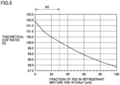
- Fig. 5 is a graph illustrating the relationship between the fraction of R32 in the refrigerant mixture R32/R1234yf and the theoretical COP ratio.
- the theoretical COP ratio is the ratio of the theoretical COP in the case where the internal heat exchanger is provided to the theoretical COP in the case where the internal heat exchanger is not provided.
- the theoretical COP ratio is (the theoretical COP of the configuration with the internal heat exchanger)/(the theoretical COP of the configuration without the internal heat exchanger).
- Fig. 5 shows the calculation result when the temperature at the inlet of the internal heat exchanger changes by 10 degrees due to heat exchange.
- the mass fraction of R32 exceeds 30%, the theoretical COP of the configuration where the internal heat exchanger is provided will not increase.
- the effective range W1 of the mass fraction of R32 in the case where the internal heat exchanger is provided is 0% to 30%.
- Fig. 6 is a graph illustrating the relationship between the fraction of R32 in the refrigerant mixture R32/R1234yf and the saturation temperature at standard atmospheric pressure and the GWP value.
- the saturation temperature of a refrigerant depends on the dryness of the refrigerant at the same pressure but with a temperature gradient.
- the results illustrated in Fig. 6 represent the saturation temperature at the standard atmospheric pressure when the dryness is 0.5.
- a refrigerant has a saturated temperature of -44.4°C or more at the standard atmospheric pressure, it is effective in the case where the internal heat exchanger is provided.
- a refrigerant has a GWP of 205 or less, it is effective in the case where the internal heat exchanger is provided.
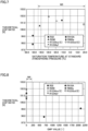
- Fig. 7 is a graph illustrating the relationship between the saturation temperature of various refrigerants at standard atmospheric pressure and the theoretical COP ratio.
- Fig. 8 is a graph illustrating the relationship between the GWP values of various refrigerants and the theoretical COP ratio.
- the COP in the case where the internal heat exchanger is not provided was calculated by assuming the degree of superheat (SH) of the sucked refrigerant is 10 degrees, the degree of supercooling (SC) is 0 degrees, the evaporation temperature (ET) is 17°C, the condensation temperature (CT) is 40°C, and the compressor efficiency is 1.
- the COP in the case where the internal heat exchanger is provided was calculated by assuming that the capacity of the evaporator is the same, the degree of superheat (SH) of the refrigerant at the outlet of the evaporator is controlled at 0 degrees by using the expansion valve, and the internal heat exchanger exchanges an amount of heat of 10°C at the inlet.
- the saturation temperature range W3 and the GWP value range W4 which are obtained by applying the range W1 to Fig. 6 and effective in the case where the internal heat exchanger is provided are generally true for various refrigerants except for R32 and R410A.
- the refrigerant suitably used in the present embodiment has such a characteristic that the saturated temperature at the standard atmospheric pressure is - 44.4°C or more or the GWP is 205 or less.
- the developer or the user of the air conditioner may use this characteristic as an indicator to select a refrigerant.
- the internal heat exchanger 250 is configured to operate mainly during the cooling operation, it also may be configured to operate mainly during the heating operation. Alternatively, as illustrated in the following modifications, an expansion valve may be further provided.
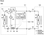
- Fig. 9 is a diagram illustrating a modification of the air conditioner illustrated in Fig. 1 .
- the air conditioner 1010 illustrated in Fig. 9 includes a refrigerant circuit 510 instead of the refrigerant circuit 500.
- the refrigerant circuit 510 further includes a second expansion valve 231 inside the outdoor unit 1011 as compared with the refrigerant circuit 500.
- An electronic expansion valve can be used as the expansion valve 231.
- the expansion valve 230 is connected between the first flow channel R1 of the internal heat exchanger 250 and the outdoor heat exchanger 210.
- the controller 100 fully opens the second expansion valve 231 and controls the superheat (SH) of the refrigerant at the outlet of the evaporator with the expansion valve 230 during the cooling operation, and fully opens the expansion valve 230 and controls the superheat (SH) of the refrigerant at the outlet of the evaporator with the second expansion valve 231 during the heating operation. This makes it possible to improve the efficiency of heat exchange in the internal heat exchanger 250 during both the cooling operation and the heating operation.
- the internal heat exchanger 250 may be any heat exchanger as long as it exchanges heat between the high-pressure refrigerant that has passed through the condenser and the low-pressure refrigerant to be sucked into the compressor, and for example, it may be a double-tube heat exchanger composed of an inner pipe and an outer pipe, or may be a heat exchanger in which the high-pressure pipe and the low-pressure pipe are brazed and brought into contact with each other by soldering or the like to perform heat exchange.
- the air conditioner illustrated in Figs. 1 and 9 is provided with a four-way valve, the air conditioner may not be provided with a four-way valve and thereby is used exclusively for cooling.
- the flow of the refrigerant in the heating operation mode is indicated by a solid line
- the flow of the refrigerant in the cooling operation mode is indicated by a broken line.
- the controller 100 changes the frequency of the compressor 200 so as to bring the indoor temperature to a target (set) temperature.
- Fig. 10 is a flowchart illustrating the control of the expansion valve 230.
- step S21 the controller 100 sets the opening degree of the expansion valve 230 to a predefined value. After a certain period of time has elapsed, in step S22, the controller 100 initializes the variable Count to 0. Thereafter, in step S23, the controller 100 decreases the opening degree of the expansion valve 230 by a certain value. After a certain period of time has elapsed, in step S24, the controller 100 determines whether or not the degree of superheat (SH) of the refrigerant at the outlet of the evaporator has changed.
- SH superheat
- the degree of superheat (SH) of the refrigerant at the outlet of the evaporator is calculated by subtracting the evaporation temperature of the refrigerant obtained by the temperature sensor 262 from the refrigerant temperature at the outlet of the evaporator obtained by the temperature sensor 263.
- the degree of refrigerant superheat (SH) at the outlet of the evaporator is calculated by subtracting the evaporation temperature of the refrigerant obtained by the temperature sensor 264 from the refrigerant temperature at the outlet of the evaporator obtained by the temperature sensor 265.
- step S24 determines whether the degree of superheat (SH) of the refrigerant at the outlet of the evaporator is not changed, since the state of the refrigerant at the outlet of the evaporator is not changed from the gas-liquid two-phase state.
- the controller 100 adds 1 to the variable Count in step S25, returns the procedure to step S23, and decreases the opening degree of the expansion valve 230 by a certain value.
- step S24 the controller 100 proceeds the procedure to step S26 to determine whether or not the variable Count is 0.
- step S26 If the determination result is NO in step S26, in other words, if the variable Count is not 0, since the degree of superheat (SH) of the refrigerant at the outlet of the evaporator has been appropriately controlled in steps S23 to S25, the controller 100 ends the procedure of this flowchart. On the other hand, if the determination result is YES in step S26, since the variable Count is 0, the procedure passes step S24 once without going through step S25. Since the refrigerant at the outlet of the evaporator is in a superheated gas state at the default opening degree in step S21, and the degree of superheat (SH) of the refrigerant is further increased as a result of the process in step S23 from that state, the state cannot be regarded as an appropriate state.
- the controller 100 increases the opening degree of the expansion valve 230 by a certain value in step S27. After a certain period of time has elapsed, in step S28, the controller 100 determines whether or not the degree of superheat (SH) of the refrigerant at the outlet of the evaporator has changed.
- SH superheat
- step S28 determines whether the degree of superheat (SH) of the refrigerant at the outlet of the evaporator has changed, since there is a change in the degree of superheat (SH) of the refrigerant at the outlet of the evaporator.
- the process returns to step S27 where the controller 100 increases the opening degree of the expansion valve 230 by a certain value.
- step S28 if there is no change in the degree of superheat (SH) of the refrigerant at the outlet of the evaporator, it can be determined that the refrigerant at the outlet of the evaporator is in a gas-liquid two-phase state (the degree of superheat is 0), and the heat exchange efficiency of the evaporator is good, the controller 100 ends the procedure of this flowchart.
- SH degree of superheat
- the procedure of the flowchart in Fig. 10 is performed again, whereby the opening degree of the expansion valve 230 is set to bring the degree of superheat of the refrigerant at the outlet of the evaporator to substantially zero.
- the opening degree of the expansion valve 230 determined in a previous procedure may be used as the predefined value in step S21.
- the degree of superheat (SH) of the refrigerant at the outlet of the evaporator is controlled to approach the target value (zero), however, the target value of the degree of superheat (SH) of the refrigerant discharged from the compressor 200 or the target value of the temperature of the refrigerant discharged from the compressor 200 corresponding to the degree of superheat (SH) of the refrigerant at the outlet of the evaporator may be determined in advance, and the degree of superheat (SH) or the temperature of the refrigerant discharged from the compressor may be controlled to be the target value. Also, the expansion valve 231 in the configuration of Fig. 9 during the heating operation may be controlled in the same manner as in Fig. 10 with the expansion valve 230 fixed to fully open.
- the method for calculating the degree of superheat (SH) of the refrigerant at the outlet of the evaporator described in the flowchart of Fig. 10 was based on temperature sensors.
- the degree of superheat (SH) of the refrigerant changes.
- the degree of superheat (SH) of the refrigerant at the outlet of the evaporator obtained by this method becomes smaller, and when the refrigerant has a larger temperature gradient, the degree of superheat (SH) of the refrigerant at the outlet of the evaporator obtained by this method becomes larger.
- the degree of superheat (SH) is about 5 degrees, the performance of the evaporator does not drop that much, and thus, the degree of superheat (SH) may be controlled to 5 degrees or less to tolerate some error.
- the air conditioner of the first embodiment it is possible to ensure the degree of superheat (SH) of the refrigerant to be sucked into the compressor without deteriorating the performance of the evaporator even when a low GWP refrigerant is used, which makes it possible to improve the COP of the air conditioner.
- SH superheat
- Fig. 11 is a diagram illustrating a configuration of an air conditioner according to a second embodiment.
- the air conditioner 1100 illustrated in Fig. 11 includes a refrigerant circuit 600 instead of the refrigerant circuit 500 illustrated in Fig. 1 .
- the refrigerant circuit 600 includes a pressure-reducing heat exchanger 270 inside the outdoor unit 1101 instead of the internal heat exchanger 250 and the expansion valve 230 in the refrigerant circuit 500.
- the pressure-reducing heat exchanger 270 includes a low-pressure pipe 271 through which low-pressure refrigerant flows and a first medium-pressure pipe 272 through which medium-pressure refrigerant flows.
- the inner diameter of the first medium-pressure pipe 272 is configured to be smaller than that of the low-pressure pipe 271. Further, the inner diameter of the first medium-pressure pipe 272 is configured to be smaller than that of the pipes connected to both ends of the medium-pressure pipe 272 so as to reduce the pressure of the high-pressure refrigerant flowing out from the condenser.
- the first low-pressure pipe 271 and the first medium-pressure pipe 272 are in contact with each other so as to exchange heat.
- the two pipes are brazed by solder or the like, and are brought into contact with each other so as to exchange heat between the two pipes.
- Fig. 12 is a cross-sectional view illustrating a specific example of the pressure-reducing heat exchanger 270.
- the diameter of the low-pressure pipe 271 is ⁇ 9.52
- the diameter of the first medium-pressure pipe 272 is ⁇ 3.0.
- the diameter of the low-pressure pipe 271 is set larger so as to reduce the effect of the pressure loss
- the diameter of the medium-pressure pipe 272 is set smaller so as to reduce the pressure from high pressure to low pressure.
- Fig. 13 is a diagram illustrating another specific example of the pressure-reducing heat exchanger 270.
- the first medium-pressure pipe 272 is spirally wound around the low-pressure pipe 271. This increases the contact area of the first medium-pressure pipe 272 per unit length of the low-pressure pipe 271, which improves the heat exchange efficiency. Accordingly, the length of the low-pressure pipe 271 for exchanging a required amount of heat in the pressure-reducing heat exchanger 270 can be made shorter than the length along which the medium-pressure pipe 272 is not wound. Since the length of the low-pressure pipe 271 is shortened, the pipe can be easily routed in a machine room. Further, since the pressure loss of the low-pressure pipe 271 is reduced by shortening the length, it is possible to reduce the diameter of the low-pressure pipe 271.
- the first medium-pressure pipe 272 is one pipe, and since one pipe can only form one fixed throttle, a plurality of pipes may be installed in parallel.
- Fig. 14 is a diagram illustrating a configuration of a modification of the air conditioner illustrated in Fig. 11 .
- the air conditioner 1110 illustrated in Fig. 14 includes a refrigerant circuit 601 instead of the refrigerant circuit 600 illustrated in Fig. 11 .
- the refrigerant circuit 601 includes a pressure-reducing heat exchanger 280 inside the outdoor unit 1111 instead of the pressure-reducing heat exchanger 270 in the configuration of the refrigerant circuit 600.
- the pressure-reducing heat exchanger 280 further includes a second medium-pressure pipe 273 in addition to the low-pressure pipe 271 and the first medium-pressure pipe 272.
- the medium-pressure pipe 272 and the medium-pressure pipe 273 have different diameters.
- the flow channel may be switched by the switching valve 232 so that the refrigerant flows through a pipe having an optimal inner diameter corresponding to the refrigerant circulation amount, or the pipe through which the refrigerant flows may be changed between the cooling operation and the heating operation.
- the diameter of the medium-pressure pipe through which the refrigerant flows during the heating operation is smaller than the diameter of the medium-pressure pipe through which the refrigerant flows during the cooling operation.
- the temperature difference between the air to be heat-exchanged by the indoor heat exchanger 110 and the air to be heat-exchanged by the outdoor heat exchanger 210 is larger during the heating operation than during the cooling operation, and thereby, it is suitable to increase the throttle amount in the medium-pressure pipe during the heating operation than during the cooling operation.
- JIS Japan Industrial Standard
- the air temperature at the inlet of the outdoor heat exchanger 210 is 35°C
- the air temperature at the inlet of the indoor heat exchanger 110 is 27°C
- the temperature difference between the two air temperatures is 8°C.
- the air temperature at the inlet of the indoor heat exchanger 110 is 20°C
- the air temperature at the inlet of the outdoor heat exchanger 210 is 7°C
- the temperature difference between the two air temperatures is 13°C.
- Fig. 15 is a cross-sectional view illustrating a configuration example of the pressure-reducing heat exchanger 280. As illustrated in Fig. 15 , when there are a plurality of medium-pressure pipes, the plurality of medium-pressure pipes are configured to have different diameters, and are disposed in contact with the low-pressure pipe to exchange heat.
- the diameter of the low-pressure pipe 271 is ⁇ 9.52
- the diameter of the first intermediate-pressure pipe 272 is ⁇ 3.0
- the diameter of the second intermediate-pressure pipe 273 is ⁇ 2.5.
- the diameter of the low-pressure pipe 271 should be larger to reduce the influence of the pressure loss, and the diameters of the medium-pressure pipes 272 and 273 should be smaller to reduce the pressure from a high pressure to a low pressure.
- the refrigerant flows through the medium-pressure pipe 273 having a diameter of 2.5 mm during the heating operation, and flows through the medium-pressure pipe 272 having a diameter of 3.0 mm during the cooling operation.
- the air conditioner of the second embodiment in addition to the effects exhibited by the air conditioner according to the first embodiment, since the temperature difference in the heat exchanger can always be ensured in either the cooling operation or the heating operation, the performance of the air conditioner can be improved in both the cooling operation and the heating operation. Further, since the expansion valve 230 is not provided, the air conditioner can be made cheaper.
- the present disclosure relates to an air conditioner.
- the air conditioner 1000 illustrated in Fig. 1 includes a refrigerant, a refrigerant circuit 500, a heat exchanger 250, and a controller 100.
- the refrigerant circuit 500 includes at least a compressor 200, a condenser (an outdoor heat exchanger 210) and an evaporator (an indoor heat exchanger 110), and is configured to circulate the refrigerant.
- the heat exchanger 250 includes a first flow channel R1 through which the refrigerant that has passed through the condenser (the outdoor heat exchanger 210) flows and a second flow channel R2 through which the refrigerant to be sucked into the compressor 200 flows, and is configured to exchange heat between the refrigerant passing through the first flow channel R1 and the refrigerant passing through the second flow channel R2.
- the controller 100 is configured to control the refrigerant circuit 500 so as to bring the degree of superheat of the refrigerant flowing through an outlet of the evaporator (the indoor heat exchanger 110) to 5 degrees or less.
- the refrigerant circuit 500 illustrated in Fig. 1 further includes an expansion valve 230 configured to expand the refrigerant condensed in the condenser (the outdoor heat exchanger 210).
- the controller 100 controls an opening degree of the expansion valve 230 to change the degree of superheat of the refrigerant flowing through the outlet of the evaporator (the indoor heat exchanger 110).
- the condenser (the outdoor heat exchanger 210) is configured to condense the refrigerant
- the evaporator (the indoor heat exchanger 110) is configured to evaporate the refrigerant.
- the refrigerant circuit 500 further includes a four-way valve 240 that changes the flow direction of the refrigerant passing through the condenser (the outdoor heat exchanger 210) and the evaporator (the indoor heat exchanger 110) from the flow direction during the cooling operation so as to cause the condenser (the outdoor heat exchanger 210) to evaporate the refrigerant and cause the evaporator (the indoor heat exchanger 110) to condense the refrigerant during the heating operation.
- the first flow channel R1 of the heat exchanger 250 is disposed between the condenser (the outdoor heat exchanger 210) and the expansion valve 230, and the second flow channel R2 of the heat exchanger 250 is disposed between the four-way valve 240 and the inlet of the compressor 200.
- the pressure of the refrigerant passing through the first flow channel (the middle-pressure pipe 272) is higher than the pressure of the refrigerant passing through the second flow channel (the low-pressure pipe 271), and the inner diameter of the pipe for the first flow channel (the middle-pressure pipe 272) is smaller than the inner diameter of the pipe for the second flow channel (the low-pressure pipe 271).
- the condenser (the outdoor heat exchanger 210) is configured to condense the refrigerant
- the evaporator (the indoor heat exchanger 110) is configured to evaporate the refrigerant.
- the refrigerant circuit 600 further includes a four-way valve 240 that changes the flow direction of the refrigerant passing through the condenser (the outdoor heat exchanger 210) and the evaporator (the indoor heat exchanger 110) from the flow direction during the cooling operation so as to cause the condenser (the outdoor heat exchanger 210) to evaporate the refrigerant and cause the evaporator (the indoor heat exchanger 110) to evaporate the refrigerant during the heating operation.
- the first flow channel (the middle-pressure pipe 272) of the pressure-reducing heat exchanger 270 is disposed between the condenser (the outdoor heat exchanger 210) and the evaporator (the indoor heat exchanger 110).
- the second flow channel (the low-pressure pipe 271) of the pressure-reducing heat exchanger 270 is disposed between the four-way valve 240 and the inlet of the compressor 200.
- the first flow channel includes a first pipe (the medium-pressure pipe 272) and a second pipe (the medium-pressure pipe 273) which is provided in parallel with the first pipe (the medium-pressure pipe 272) and has an inner diameter smaller than that of the first pipe (the medium-pressure pipe 272).
- the air conditioner 1110 further includes a switching valve 232 to switch the refrigerant to flow through the first pipe (the middle-pressure pipe 272) or the second pipe (the medium-pressure pipe 273).
- the controller 100 controls the switching valve 232 to cause the refrigerant to flow through the first pipe (the medium-pressure pipe 272) during the cooling operation and cause the refrigerant to flow through the second pipe (the medium-pressure pipe 273) during the heating operation.
- the degree of superheat of the refrigerant flowing through the outlet of the evaporator is 0 degrees, and the degree of superheat of the refrigerant to be sucked into the compressor 200 is greater than 0 degrees.
- the refrigerant used in the refrigerant circuit 500 has a global warming coefficient of 205 or less, or a saturation temperature of -44.4°C or more at a standard atmospheric pressure.
- the refrigerant has a global warming coefficient of 205 or less and a saturation temperature of -44.4°C or more at a standard atmospheric pressure.
- the refrigerant includes R32 and R1234yf, and a mass fraction of R32 in the refrigerant is 30% or less.
- 100 controller; 101: CPU; 102: memory; 110: indoor heat exchanger; 120: indoor blower; 200: compressor; 210: outdoor heat exchanger; 220: outdoor blower; 230, 231: expansion valve; 232: switching valve; 240: four-way valve; 250: internal heat exchanger; 262, 263, 264, 265: temperature sensor; 270, 280: pressure-reducing heat exchanger; 271: low-pressure pipe; 272, 273: medium-pressure pipe; 310, 320: pipe; 500, 510, 600, 601: refrigerant circuit; 1000, 1010, 1100, 1110: air conditioner; 1001, 1011, 1101, 1111: outdoor unit; 1002: indoor unit; P1, P2, P3, P4: port; R1: first flow channel; R2: second flow channel.
Landscapes
- Engineering & Computer Science (AREA)
- Mechanical Engineering (AREA)
- General Engineering & Computer Science (AREA)
- Physics & Mathematics (AREA)
- Thermal Sciences (AREA)
- Chemical & Material Sciences (AREA)
- Combustion & Propulsion (AREA)
- Compression-Type Refrigeration Machines With Reversible Cycles (AREA)
Abstract
Description
- The present disclosure relates to an air conditioner.
- Due to the European refrigerant regulations and other requirements, a refrigerant used in a refrigeration cycle of an air conditioner is required to have a low GWP (global warming potential).
-
WO 2020/144764 discloses an example of an air conditioner that uses such a refrigerant with a low GWP to improve the coefficient of performance. In order to increase efficiency, the air conditioner includes an internal heat exchanger. - PTL 1:
WO 2020/144764 - However, even if a refrigerant has a low GWP, if it is used as a single refrigerant, the pressure of the refrigerant may become too low to deteriorate the energy-saving performance. For this reason, it is considered to mix the refrigerant with other refrigerants. In such a case, the problem is how to mix the refrigerants so as to improve the final coefficient of performance of the air conditioner.
- The present disclosure has been made to solve the aforementioned problem, and an object of the present disclosure is to provide an air conditioner with an improved coefficient of performance.
- The present disclosure relates to an air conditioner. The air conditioner includes a refrigerant, a refrigerant circuit, a heat exchanger, and a controller. The refrigerant circuit includes at least a compressor, a condenser and an evaporator, and is configured to circulate the refrigerant. The heat exchanger includes a first flow channel through which the refrigerant that has passed through the condenser flows and a second flow channel through which the refrigerant to be sucked into the compressor flows, and is configured to exchange heat between the refrigerant passing through the first flow channel and the refrigerant passing through the second flow channel. The controller is configured to control the refrigerant circuit so as to bring a degree of superheat of the refrigerant flowing through an outlet of the evaporator to 5 degrees or less.
- The air conditioner according to the present disclosure can ensure the degree of superheat of the sucked refrigerant without decreasing the heat exchange performance of the evaporator. This improves the coefficient of performance of the air conditioner that uses an internal heat exchanger to exchange heat between the refrigerant that has passed through the condenser and the refrigerant to be sucked into the compressor.
-
-
Fig. 1 is a diagram illustrating a configuration of anair conditioner 1000 according to a first embodiment; -
Fig. 2 is a diagram illustrating a comparison of theoretical coefficients of performance (hereinafter referred to as "theoretical COP") of the air conditioner when various types of refrigerant are used; -
Fig. 3 is a PH diagram of a refrigeration cycle apparatus that uses R290 as a refrigerant and is not provided with an internal heat exchanger; -
Fig. 4 is a PH diagram of a refrigeration cycle apparatus that uses R290 as a refrigerant and is provided with an internal heat exchanger; -
Fig. 5 is a graph illustrating the relationship between the fraction of R32 in a refrigerant mixture R32/R1234yf and the theoretical COP ratio; -
Fig. 6 is a graph illustrating the relationship between the fraction of R32 in the refrigerant mixture R32/R1234yf and the saturation temperature at standard atmospheric pressure and the GWP value; -
Fig. 7 is a graph illustrating the relationship between the saturation temperature of various refrigerants at standard atmospheric pressure and the theoretical COP ratio; -
Fig. 8 is a graph illustrating the relationship between the GWP values of various refrigerants and the theoretical COP ratios; -
Fig. 9 is a diagram illustrating a modification of the air conditioner illustrated inFig. 1 ; -
Fig. 10 is a flowchart illustrating the control of theexpansion valve 230; -
Fig. 11 is a diagram illustrating a configuration of an air conditioner according to a second embodiment; -
Fig. 12 is a cross-sectional view illustrating a specific example of a pressure-reducingheat exchanger 270; -
Fig. 13 is a diagram illustrating another specific example of the pressure-reducingheat exchanger 270; -
Fig. 14 is a diagram illustrating a configuration of a modification of the air conditioner illustrated inFig. 11 ; and -
Fig. 15 is a cross-sectional view illustrating a configuration example of a pressure-reducingheat exchanger 280. - Hereinafter, embodiments of the present disclosure will be described in detail with reference to the drawings. In the following description, a plurality of embodiments will be described, and appropriate combinations of components described in the respective embodiments are also originally intended. In the drawings, the same or corresponding parts are denoted by the same reference numerals, and the description thereof will not be repeated. In the following drawings, the dimensions of each component may be different from the actual ones.
-
Fig. 1 is a diagram illustrating a configuration of anair conditioner 1000 according to a first embodiment. Theair conditioner 1000 illustrated inFig. 1 includes arefrigerant circuit 500, aninternal heat exchanger 250, and acontroller 100. - The
refrigerant circuit 500 includes at least acompressor 200, anoutdoor heat exchanger 210, anexpansion valve 230 and anindoor heat exchanger 110, and is configured to circulate the refrigerant. The refrigerant used in the present embodiment has a GWP value or a saturation temperature at standard atmospheric pressure in a certain range to be described later in detail. - In the example of
Fig. 1 , therefrigerant circuit 500 includes acompressor 200, anoutdoor heat exchanger 210, anoutdoor blower 220, anexpansion valve 230, a four-way valve 240, anindoor heat exchanger 110, and anindoor blower 120. The four-way valve 240 has ports P1 to P4. A linear expansion valve (LEV), for example, can be used as theexpansion valve 230. - The
refrigerant circuit 500 is divided into anoutdoor unit 1001 and anindoor unit 1002. Theoutdoor unit 1001 includes acompressor 200, a four-way valve 240, anoutdoor heat exchanger 210, anoutdoor blower 220, anexpansion valve 230, acontroller 100, and aninternal heat exchanger 250. Theindoor unit 1002 includes anindoor heat exchanger 110 and anindoor blower 120. Theoutdoor unit 1001 and theindoor unit 1002 are connected by apipe 310 and apipe 320. - The
compressor 200 is configured to change the operating frequency according to a control signal received from thecontroller 100. Specifically, thecompressor 200 incorporates an inverter-controlled drive motor with variable rotation speed, and the rotational speed of the drive motor changes as the operating frequency is changed. The output of thecompressor 200 is adjusted by changing the operating frequency of thecompressor 200. Thecompressor 200 may be any type of compressors such as a rotary compressor, a reciprocating compressor, a scroll compressor, or a screw compressor. - The four-
way valve 240 is controlled by a control signal received from thecontroller 100 to switch the operation mode of the air conditioner to a cooling operation mode or a heating operation mode. In the cooling operation mode, as illustrated by the broken lines, the port P1 communicates with the port P4, and the port P2 communicates with the port P3. In the heating operation mode, as illustrated by the solid lines, the port P1 communicates with the port P3, and the port P2 communicates with the port P4. When thecompressor 200 is operated in the cooling operation mode, the refrigerant is circulated in the refrigerant circuit in the direction indicated by the broken arrows. When thecompressor 200 is operated in the heating operation mode, the refrigerant is circulated in the refrigerant circuit in the direction indicated by the solid arrows. - The
internal heat exchanger 250 includes a flow channel R1 and a flow channel R2. During the cooling operation, high-pressure high-temperature refrigerant that has passed through the condenser (the outdoor heat exchanger 210) flows through the flow channel R1. During the cooling operation, low-pressure and low-temperature refrigerant to be sucked into thecompressor 200 flows through the flow channel R2. During the cooling operation, theinternal heat exchanger 250 exchanges heat between the high-pressure high-temperature refrigerant that has passed through the condenser (the outdoor heat exchanger 210) and the low-pressure low-temperature refrigerant to be sucked into thecompressor 200. - The
air conditioner 1000 further includestemperature sensors 262 to 265. Thetemperature sensor 262 is disposed in theindoor heat exchanger 110, and is configured to measure a refrigerant temperature T262 which is an evaporation temperature of the refrigerant during the cooling operation or a condensation temperature of the refrigerant during the heating operation. Thetemperature sensor 263 is disposed in a pipe that connects theindoor heat exchanger 110 to the port P3 of the four-way valve 240, and is configured to measure a temperature T263 of the refrigerant. Thetemperature sensor 264 is disposed in theoutdoor heat exchanger 210, and is configured to measure a refrigerant temperature T264 which is a condensation temperature of the refrigerant during the cooling operation or an evaporation temperature of the refrigerant during the heating operation. Thetemperature sensor 265 is disposed in a pipe connecting theoutdoor heat exchanger 210 and the port P4 of the four-way valve 240, and is configured to measure a temperature T265 of the refrigerant. - The
controller 100 controls the opening degree of theexpansion valve 230 so as to adjust the SH (the degree of superheat) of the refrigerant at an outlet of the evaporator according to the outputs from thetemperature sensors 262 to 265. - The
controller 100 includes a CPU (Central Processing Unit) 101, a memory 102 (such as a ROM (Read Only Memory) or a RAM (Random Access Memory)), an input/output buffer (not shown), and the like. TheCPU 101 loads programs stored in the ROM into the RAM or the like and executes the programs. The programs stored in the ROM are programs that describe the processing procedure of thecontroller 100. Thecontroller 100 controls each device in theair conditioner 1000 in accordance with these programs. This control is not limited to being processed by software, but may be processed by dedicated hardware (electronic circuit). - As described in the above, the refrigerant circuit of the
air conditioner 1000 includes thecompressor 200, theoutdoor heat exchanger 210, theoutdoor blower 220, theexpansion valve 230, the four-way valve 240, theinternal heat exchanger 250, theindoor heat exchanger 110, and theindoor blower 120. During the cooling operation, theinternal heat exchanger 250 exchanges heat between the high-pressure refrigerant flowing out from theoutdoor heat exchanger 210 through the flow channel R1 and the low-pressure refrigerant flowing through the flow channel R2 into thecompressor 200. - Next, various types of refrigerants to be used in the air conditioner having the configuration illustrated in
Fig. 1 will be examined.Fig. 2 is a diagram illustrating a comparison of theoretical coefficients of performance (hereinafter referred to as "theoretical COP") of the air conditioner when various types of refrigerants are used. The results ofFig. 2 are obtained through calculations by setting the supercooling degree (SC) to 0 degrees, the evaporation temperature (ET) to 17°C, the condensation temperature (CT) to 40°C, and the compressor efficiency to 1. - As illustrated in
Fig. 2 , the theoretical COP of a hydrofluorocarbon refrigerant (hereinafter referred to as "HFC refrigerant") such as R32 and R410A decreases as the degree of superheat (SH) of the refrigerant to be sucked into the compressor increases. On the other hand, the theoretical COP of a hydrocarbon refrigerant (hereinafter referred to as "HC refrigerant") such as R290 or R600a increases as the degree of superheat (SH) of the sucked refrigerant increases. Similar to the HC refrigerant, the theoretical COP of a hydrofluoroolefin refrigerant (hereinafter referred to as "HFO refrigerant") such as R1234ze(E), R1233zd(E) or R1234yf also increases as the degree of superheat (SH) of the sucked refrigerant increases. - This is because when the degree of superheat (SH) of the refrigerant to be sucked into the compressor increases, the increase ratio of the evaporator enthalpy difference is greater than the decrease ratio of the refrigerant circulation amount in the case of the HC refrigerant, the HFO refrigerant and other refrigerants than in the case of the HFC refrigerant.
- Therefore, in an air conditioner that uses the HC refrigerant or the HFO refrigerant, it is theoretically possible to make the air conditioner operate with high performance by controlling the degree of superheat of the sucked refrigerant. However, as the degree of superheat (SH) of the refrigerant to be sucked into the compressor increases, the proportion of the gas refrigerant in the evaporator increases, which decreases the performance of the evaporator, and whereby the evaporation temperature decreases, resulting in a problem that the actual coefficient of performance (hereinafter referred to as "actual COP") of the air conditioner will decrease.
- In order to solve this problem, according to the air conditioner of the present embodiment, in addition to controlling the degree of superheat at the outlet of the evaporator to 5 degrees or less and using an internal heat exchanger, by using a low GWP refrigerant that satisfies certain conditions, it is possible to make the air conditioner operate with high performance while preventing the performance of the evaporator from decreasing.
- Next, how the PH diagram changes depending on the presence or absence of an internal heat exchanger will be described with reference to
Figs. 3 to 4 . -
Fig. 3 is a PH diagram of a refrigeration cycle apparatus that uses R290 as a refrigerant and is not provided with an internal heat exchanger.Fig. 4 is a PH diagram of a refrigeration cycle apparatus that uses R290 as a refrigerant and is provided with an internal heat exchanger. - The result in the case where the internal heat exchanger is not provided as illustrated in
Fig. 3 was calculated by assuming the degree of superheat (SH) of the sucked refrigerant is 10 degrees, the degree of supercooling (SC) of the refrigerant at the outlet of the condenser is 0 degrees, the evaporation temperature (ET) is 17°C, the condensation temperature (CT) is 40°C, and the compressor efficiency is 1. On the other hand, the result in the case where the internal heat exchanger is provided as illustrated inFig. 4 was calculated by assuming that the capacity of the evaporator is the same, the degree of superheat (SH) of the refrigerant at the outlet of the evaporator is controlled at 0 degrees by using theexpansion valve 230, and the low-temperature and low-pressure refrigerant at the outlet of the evaporator increases by 10°C as theinternal heat exchanger 250 exchanges heat (Δh) with the high-temperature and high-pressure refrigerant at the outlet of the condenser. In other words, the degree of superheat (SH) of the sucked refrigerant is 10 degrees. Since the capacity of the compressor is the same in bothFig. 3 and Fig. 4 , the evaporation temperature (ET) is the same regardless of the refrigerant temperature at the outlet of the evaporator. - The theoretical COP is equal to 10.82 in both the configuration where the internal heat exchanger is provided and the configuration where the internal heat exchanger is not provided. However, in the configuration where the internal heat exchanger is not provided, the degree of superheat (SH) of the refrigerant at the outlet of the evaporator is equal to the degree of superheat of the refrigerant to be sucked into the compressor. Therefore, when the degree of superheat of the sucked refrigerant is 10 degrees, the degree of dryness of the refrigerant is equal to 1 before the outlet of the evaporator, and thereby, the performance of the evaporator decreases by an amount corresponding to a decrease in the heat exchange performance caused by the portion of the gas refrigerant. Therefore, the evaporation temperature ET becomes lower than 17°C, and the actual COP becomes lower than that of the configuration where the internal heat exchanger is provided (evaporator SH= 0 degrees). By providing an internal heat exchanger in the air conditioner that uses R290 as the refrigerant illustrated in
Figs. 3 and 4 , it is possible to improve the performance by increasing the degree of superheat (SH) of the refrigerant to be sucked into the compressor without reducing the actual COP. - Generally, a refrigerant is required to have such a characteristic that the theoretical COP increases as the superheating degree (SH) of the refrigerant to be sucked into the compressor increases. In other words, generally a refrigerant is required to improve the actual COP when an internal heat exchanger is provided. As described with reference to
Fig. 2 , in the case of an HFC refrigerant, the theoretical COP decreases when the degree of superheat (SH) of the refrigerant to be sucked into the compressor increases, but in the case of an HFO refrigerant, the theoretical COP increases when the degree of superheat (SH) of the refrigerant to be sucked into the compressor increases. - Currently, an HFO refrigerant such as R1234yf is used in a car air conditioner or the like. However, in a residential air conditioner or the like which is used in an airtight and well-insulated space and is configured to pursue better energy saving performance, in order to prevent the evaporation temperature from becoming excessively low with respect to an indoor temperature, it has been studied to use R32, which is an HFC refrigerant used in a residential air conditioner, as a mixture with R1234yf.
- The following study examines that when a refrigerant mixture composed of R32 (an HFC refrigerant) and R1234yf (an HFO refrigerant) is used and the superheating degree (SH) of the refrigerant to be sucked into the compressor is ensured, to what extent an increase in the fraction of R32 will decrease the theoretical COP.
-
Fig. 5 is a graph illustrating the relationship between the fraction of R32 in the refrigerant mixture R32/R1234yf and the theoretical COP ratio. The theoretical COP ratio is the ratio of the theoretical COP in the case where the internal heat exchanger is provided to the theoretical COP in the case where the internal heat exchanger is not provided. In other words, the theoretical COP ratio is (the theoretical COP of the configuration with the internal heat exchanger)/(the theoretical COP of the configuration without the internal heat exchanger). -
Fig. 5 shows the calculation result when the temperature at the inlet of the internal heat exchanger changes by 10 degrees due to heat exchange. As can be seen fromFig. 5 , when the mass fraction of R32 exceeds 30%, the theoretical COP of the configuration where the internal heat exchanger is provided will not increase. In other words, the effective range W1 of the mass fraction of R32 in the case where the internal heat exchanger is provided is 0% to 30%. -
Fig. 6 is a graph illustrating the relationship between the fraction of R32 in the refrigerant mixture R32/R1234yf and the saturation temperature at standard atmospheric pressure and the GWP value. The saturation temperature of a refrigerant depends on the dryness of the refrigerant at the same pressure but with a temperature gradient. The results illustrated inFig. 6 represent the saturation temperature at the standard atmospheric pressure when the dryness is 0.5. - The effective range W1 (0% to 30%) of the mass fraction of R32 in the case where the internal heat exchanger is provided, which is obtained in
Fig. 5 , is also applied toFig. 6 . Thus, if a refrigerant has a saturated temperature of -44.4°C or more at the standard atmospheric pressure, it is effective in the case where the internal heat exchanger is provided. Similarly, if a refrigerant has a GWP of 205 or less, it is effective in the case where the internal heat exchanger is provided. -
Fig. 7 is a graph illustrating the relationship between the saturation temperature of various refrigerants at standard atmospheric pressure and the theoretical COP ratio.Fig. 8 is a graph illustrating the relationship between the GWP values of various refrigerants and the theoretical COP ratio. - At the time of calculating the theoretical COP ratio, the COP in the case where the internal heat exchanger is not provided was calculated by assuming the degree of superheat (SH) of the sucked refrigerant is 10 degrees, the degree of supercooling (SC) is 0 degrees, the evaporation temperature (ET) is 17°C, the condensation temperature (CT) is 40°C, and the compressor efficiency is 1. On the other hand, the COP in the case where the internal heat exchanger is provided was calculated by assuming that the capacity of the evaporator is the same, the degree of superheat (SH) of the refrigerant at the outlet of the evaporator is controlled at 0 degrees by using the expansion valve, and the internal heat exchanger exchanges an amount of heat of 10°C at the inlet. As can be seen from
Figs. 7 and 8 , the saturation temperature range W3 and the GWP value range W4 which are obtained by applying the range W1 toFig. 6 and effective in the case where the internal heat exchanger is provided are generally true for various refrigerants except for R32 and R410A. - Therefore, the refrigerant suitably used in the present embodiment has such a characteristic that the saturated temperature at the standard atmospheric pressure is - 44.4°C or more or the GWP is 205 or less. The developer or the user of the air conditioner may use this characteristic as an indicator to select a refrigerant.
- In the configuration illustrated in
Fig. 1 , theinternal heat exchanger 250 is configured to operate mainly during the cooling operation, it also may be configured to operate mainly during the heating operation. Alternatively, as illustrated in the following modifications, an expansion valve may be further provided. -
Fig. 9 is a diagram illustrating a modification of the air conditioner illustrated inFig. 1 . Theair conditioner 1010 illustrated inFig. 9 includes arefrigerant circuit 510 instead of therefrigerant circuit 500. Therefrigerant circuit 510 further includes asecond expansion valve 231 inside theoutdoor unit 1011 as compared with therefrigerant circuit 500. An electronic expansion valve can be used as theexpansion valve 231. Theexpansion valve 230 is connected between the first flow channel R1 of theinternal heat exchanger 250 and theoutdoor heat exchanger 210. - The
controller 100 fully opens thesecond expansion valve 231 and controls the superheat (SH) of the refrigerant at the outlet of the evaporator with theexpansion valve 230 during the cooling operation, and fully opens theexpansion valve 230 and controls the superheat (SH) of the refrigerant at the outlet of the evaporator with thesecond expansion valve 231 during the heating operation. This makes it possible to improve the efficiency of heat exchange in theinternal heat exchanger 250 during both the cooling operation and the heating operation. - The
internal heat exchanger 250 may be any heat exchanger as long as it exchanges heat between the high-pressure refrigerant that has passed through the condenser and the low-pressure refrigerant to be sucked into the compressor, and for example, it may be a double-tube heat exchanger composed of an inner pipe and an outer pipe, or may be a heat exchanger in which the high-pressure pipe and the low-pressure pipe are brazed and brought into contact with each other by soldering or the like to perform heat exchange. - Although the air conditioner illustrated in
Figs. 1 and9 is provided with a four-way valve, the air conditioner may not be provided with a four-way valve and thereby is used exclusively for cooling. - In
Figs. 1 and9 , the flow of the refrigerant in the heating operation mode is indicated by a solid line, and the flow of the refrigerant in the cooling operation mode is indicated by a broken line. Similar to a general air conditioner, thecontroller 100 changes the frequency of thecompressor 200 so as to bring the indoor temperature to a target (set) temperature. - The following describes the control of the
expansion valve 230 illustrated inFig. 1 and the control of theexpansion valve 230 when theexpansion valve 231 is fixed to fully open as illustrated inFig. 9 .Fig. 10 is a flowchart illustrating the control of theexpansion valve 230. - Firstly, in step S21, the
controller 100 sets the opening degree of theexpansion valve 230 to a predefined value. After a certain period of time has elapsed, in step S22, thecontroller 100 initializes the variable Count to 0. Thereafter, in step S23, thecontroller 100 decreases the opening degree of theexpansion valve 230 by a certain value. After a certain period of time has elapsed, in step S24, thecontroller 100 determines whether or not the degree of superheat (SH) of the refrigerant at the outlet of the evaporator has changed. - During the cooling operation, the degree of superheat (SH) of the refrigerant at the outlet of the evaporator is calculated by subtracting the evaporation temperature of the refrigerant obtained by the
temperature sensor 262 from the refrigerant temperature at the outlet of the evaporator obtained by thetemperature sensor 263. During the heating operation, the degree of refrigerant superheat (SH) at the outlet of the evaporator is calculated by subtracting the evaporation temperature of the refrigerant obtained by thetemperature sensor 264 from the refrigerant temperature at the outlet of the evaporator obtained by thetemperature sensor 265. - If the determination result is NO in step S24, in other words, if the degree of superheat (SH) of the refrigerant at the outlet of the evaporator is not changed, since the state of the refrigerant at the outlet of the evaporator is not changed from the gas-liquid two-phase state, the
controller 100 adds 1 to the variable Count in step S25, returns the procedure to step S23, and decreases the opening degree of theexpansion valve 230 by a certain value. - By repeating the process of steps S23 to S25, the degree of superheat (SH) of the refrigerant at the outlet of the evaporator can be brought to an optimum state where the degree of superheat is substantially zero. On the other hand, if the determination result is YES in step S24 (when the refrigerant at the outlet of the evaporator is superheated gas), the
controller 100 proceeds the procedure to step S26 to determine whether or not the variable Count is 0. - If the determination result is NO in step S26, in other words, if the variable Count is not 0, since the degree of superheat (SH) of the refrigerant at the outlet of the evaporator has been appropriately controlled in steps S23 to S25, the
controller 100 ends the procedure of this flowchart. On the other hand, if the determination result is YES in step S26, since the variable Count is 0, the procedure passes step S24 once without going through step S25. Since the refrigerant at the outlet of the evaporator is in a superheated gas state at the default opening degree in step S21, and the degree of superheat (SH) of the refrigerant is further increased as a result of the process in step S23 from that state, the state cannot be regarded as an appropriate state. Thus, thecontroller 100 increases the opening degree of theexpansion valve 230 by a certain value in step S27. After a certain period of time has elapsed, in step S28, thecontroller 100 determines whether or not the degree of superheat (SH) of the refrigerant at the outlet of the evaporator has changed. - If the determination result is NO in step S28, in other words, if the degree of superheat (SH) of the refrigerant at the outlet of the evaporator has changed, since there is a change in the degree of superheat (SH) of the refrigerant at the outlet of the evaporator, the process returns to step S27 where the
controller 100 increases the opening degree of theexpansion valve 230 by a certain value. By repeating the process of steps S27 to S28, the degree of superheat (SH) of the refrigerant at the outlet of the evaporator can be brought to an optimum state where the degree of superheat is substantially zero. On the other hand, if the determination result is YES in step S28, in other words, if there is no change in the degree of superheat (SH) of the refrigerant at the outlet of the evaporator, it can be determined that the refrigerant at the outlet of the evaporator is in a gas-liquid two-phase state (the degree of superheat is 0), and the heat exchange efficiency of the evaporator is good, thecontroller 100 ends the procedure of this flowchart. - When a certain period of time has elapsed, the procedure of the flowchart in
Fig. 10 is performed again, whereby the opening degree of theexpansion valve 230 is set to bring the degree of superheat of the refrigerant at the outlet of the evaporator to substantially zero. In this case, the opening degree of theexpansion valve 230 determined in a previous procedure may be used as the predefined value in step S21. - The control of the
expansion valve 230 has been described above. In the flowchart illustrated inFig. 10 , the degree of superheat (SH) of the refrigerant at the outlet of the evaporator is controlled to approach the target value (zero), however, the target value of the degree of superheat (SH) of the refrigerant discharged from thecompressor 200 or the target value of the temperature of the refrigerant discharged from thecompressor 200 corresponding to the degree of superheat (SH) of the refrigerant at the outlet of the evaporator may be determined in advance, and the degree of superheat (SH) or the temperature of the refrigerant discharged from the compressor may be controlled to be the target value. Also, theexpansion valve 231 in the configuration ofFig. 9 during the heating operation may be controlled in the same manner as inFig. 10 with theexpansion valve 230 fixed to fully open. - The method for calculating the degree of superheat (SH) of the refrigerant at the outlet of the evaporator described in the flowchart of
Fig. 10 was based on temperature sensors. In this method, when there is a pressure loss between temperature sensors or when there is a temperature gradient in the refrigerant, the degree of superheat (SH) of the refrigerant changes. When the refrigerant has a larger pressure loss, the degree of superheat (SH) of the refrigerant at the outlet of the evaporator obtained by this method becomes smaller, and when the refrigerant has a larger temperature gradient, the degree of superheat (SH) of the refrigerant at the outlet of the evaporator obtained by this method becomes larger. However, in real life, if the degree of superheat (SH) is about 5 degrees, the performance of the evaporator does not drop that much, and thus, the degree of superheat (SH) may be controlled to 5 degrees or less to tolerate some error. - As described in the above, according to the air conditioner of the first embodiment, it is possible to ensure the degree of superheat (SH) of the refrigerant to be sucked into the compressor without deteriorating the performance of the evaporator even when a low GWP refrigerant is used, which makes it possible to improve the COP of the air conditioner.
-
Fig. 11 is a diagram illustrating a configuration of an air conditioner according to a second embodiment. Hereinafter, the differences from the configuration ofFig. 1 will be described. Theair conditioner 1100 illustrated inFig. 11 includes arefrigerant circuit 600 instead of therefrigerant circuit 500 illustrated inFig. 1 . Therefrigerant circuit 600 includes a pressure-reducingheat exchanger 270 inside theoutdoor unit 1101 instead of theinternal heat exchanger 250 and theexpansion valve 230 in therefrigerant circuit 500. - In other words, in the
air conditioner 1100, theinternal heat exchanger 250 and theexpansion valve 230 are replaced by a pressure-reducingheat exchanger 270 which solely performs pressure reduction and heat exchange of the high-pressure refrigerant. The pressure-reducingheat exchanger 270 includes a low-pressure pipe 271 through which low-pressure refrigerant flows and a first medium-pressure pipe 272 through which medium-pressure refrigerant flows. The inner diameter of the first medium-pressure pipe 272 is configured to be smaller than that of the low-pressure pipe 271. Further, the inner diameter of the first medium-pressure pipe 272 is configured to be smaller than that of the pipes connected to both ends of the medium-pressure pipe 272 so as to reduce the pressure of the high-pressure refrigerant flowing out from the condenser. The first low-pressure pipe 271 and the first medium-pressure pipe 272 are in contact with each other so as to exchange heat. Specifically, the two pipes are brazed by solder or the like, and are brought into contact with each other so as to exchange heat between the two pipes. -
Fig. 12 is a cross-sectional view illustrating a specific example of the pressure-reducingheat exchanger 270. When the air conditioner is a room air conditioner, the diameter of the low-pressure pipe 271 is ϕ9.52, and the diameter of the first medium-pressure pipe 272 is ϕ3.0. The diameter of the low-pressure pipe 271 is set larger so as to reduce the effect of the pressure loss, and the diameter of the medium-pressure pipe 272 is set smaller so as to reduce the pressure from high pressure to low pressure. -
Fig. 13 is a diagram illustrating another specific example of the pressure-reducingheat exchanger 270. In the example illustrated inFig. 13 , the first medium-pressure pipe 272 is spirally wound around the low-pressure pipe 271. This increases the contact area of the first medium-pressure pipe 272 per unit length of the low-pressure pipe 271, which improves the heat exchange efficiency. Accordingly, the length of the low-pressure pipe 271 for exchanging a required amount of heat in the pressure-reducingheat exchanger 270 can be made shorter than the length along which the medium-pressure pipe 272 is not wound. Since the length of the low-pressure pipe 271 is shortened, the pipe can be easily routed in a machine room. Further, since the pressure loss of the low-pressure pipe 271 is reduced by shortening the length, it is possible to reduce the diameter of the low-pressure pipe 271. - In the configuration of
Fig. 11 , the first medium-pressure pipe 272 is one pipe, and since one pipe can only form one fixed throttle, a plurality of pipes may be installed in parallel. -
Fig. 14 is a diagram illustrating a configuration of a modification of the air conditioner illustrated inFig. 11 . Theair conditioner 1110 illustrated inFig. 14 includes arefrigerant circuit 601 instead of therefrigerant circuit 600 illustrated inFig. 11 . Therefrigerant circuit 601 includes a pressure-reducingheat exchanger 280 inside theoutdoor unit 1111 instead of the pressure-reducingheat exchanger 270 in the configuration of therefrigerant circuit 600. - The pressure-reducing
heat exchanger 280 further includes a second medium-pressure pipe 273 in addition to the low-pressure pipe 271 and the first medium-pressure pipe 272. The medium-pressure pipe 272 and the medium-pressure pipe 273 have different diameters. The flow channel may be switched by the switchingvalve 232 so that the refrigerant flows through a pipe having an optimal inner diameter corresponding to the refrigerant circulation amount, or the pipe through which the refrigerant flows may be changed between the cooling operation and the heating operation. Preferably, the diameter of the medium-pressure pipe through which the refrigerant flows during the heating operation is smaller than the diameter of the medium-pressure pipe through which the refrigerant flows during the cooling operation. - The reason for this is that the temperature difference between the air to be heat-exchanged by the
indoor heat exchanger 110 and the air to be heat-exchanged by theoutdoor heat exchanger 210 is larger during the heating operation than during the cooling operation, and thereby, it is suitable to increase the throttle amount in the medium-pressure pipe during the heating operation than during the cooling operation. For example, under the standard cooling conditions defined by the Japan Industrial Standard (JIS), the air temperature at the inlet of theoutdoor heat exchanger 210 is 35°C, and the air temperature at the inlet of theindoor heat exchanger 110 is 27°C, the temperature difference between the two air temperatures is 8°C. On the other hand, under the standard heating conditions, the air temperature at the inlet of theindoor heat exchanger 110 is 20°C, and the air temperature at the inlet of theoutdoor heat exchanger 210 is 7°C, the temperature difference between the two air temperatures is 13°C. -
Fig. 15 is a cross-sectional view illustrating a configuration example of the pressure-reducingheat exchanger 280. As illustrated inFig. 15 , when there are a plurality of medium-pressure pipes, the plurality of medium-pressure pipes are configured to have different diameters, and are disposed in contact with the low-pressure pipe to exchange heat. - Specifically, if the air conditioner is a room air conditioner, the diameter of the low-
pressure pipe 271 is ϕ9.52, the diameter of the first intermediate-pressure pipe 272 is ϕ3.0, and the diameter of the second intermediate-pressure pipe 273 is ϕ2.5. The diameter of the low-pressure pipe 271 should be larger to reduce the influence of the pressure loss, and the diameters of the medium-pressure pipes - As described with reference to
Fig. 14 , it is preferable that the refrigerant flows through the medium-pressure pipe 273 having a diameter of 2.5 mm during the heating operation, and flows through the medium-pressure pipe 272 having a diameter of 3.0 mm during the cooling operation. - As described above, according to the air conditioner of the second embodiment, in addition to the effects exhibited by the air conditioner according to the first embodiment, since the temperature difference in the heat exchanger can always be ensured in either the cooling operation or the heating operation, the performance of the air conditioner can be improved in both the cooling operation and the heating operation. Further, since the
expansion valve 230 is not provided, the air conditioner can be made cheaper. - Hereinafter, embodiments of the present invention will be summarized with reference to the drawings. Note that the units in parentheses correspond to those used in the cooling operation.
- The present disclosure relates to an air conditioner. The
air conditioner 1000 illustrated inFig. 1 includes a refrigerant, arefrigerant circuit 500, aheat exchanger 250, and acontroller 100. Therefrigerant circuit 500 includes at least acompressor 200, a condenser (an outdoor heat exchanger 210) and an evaporator (an indoor heat exchanger 110), and is configured to circulate the refrigerant. Theheat exchanger 250 includes a first flow channel R1 through which the refrigerant that has passed through the condenser (the outdoor heat exchanger 210) flows and a second flow channel R2 through which the refrigerant to be sucked into thecompressor 200 flows, and is configured to exchange heat between the refrigerant passing through the first flow channel R1 and the refrigerant passing through the second flow channel R2. Thecontroller 100 is configured to control therefrigerant circuit 500 so as to bring the degree of superheat of the refrigerant flowing through an outlet of the evaporator (the indoor heat exchanger 110) to 5 degrees or less. - Preferably, the
refrigerant circuit 500 illustrated inFig. 1 further includes anexpansion valve 230 configured to expand the refrigerant condensed in the condenser (the outdoor heat exchanger 210). Thecontroller 100 controls an opening degree of theexpansion valve 230 to change the degree of superheat of the refrigerant flowing through the outlet of the evaporator (the indoor heat exchanger 110). - More preferably, during the cooling operation, the condenser (the outdoor heat exchanger 210) is configured to condense the refrigerant, and the evaporator (the indoor heat exchanger 110) is configured to evaporate the refrigerant. The
refrigerant circuit 500 further includes a four-way valve 240 that changes the flow direction of the refrigerant passing through the condenser (the outdoor heat exchanger 210) and the evaporator (the indoor heat exchanger 110) from the flow direction during the cooling operation so as to cause the condenser (the outdoor heat exchanger 210) to evaporate the refrigerant and cause the evaporator (the indoor heat exchanger 110) to condense the refrigerant during the heating operation. The first flow channel R1 of theheat exchanger 250 is disposed between the condenser (the outdoor heat exchanger 210) and theexpansion valve 230, and the second flow channel R2 of theheat exchanger 250 is disposed between the four-way valve 240 and the inlet of thecompressor 200. - Preferably, as illustrated in
Figs. 11 and 12 , the pressure of the refrigerant passing through the first flow channel (the middle-pressure pipe 272) is higher than the pressure of the refrigerant passing through the second flow channel (the low-pressure pipe 271), and the inner diameter of the pipe for the first flow channel (the middle-pressure pipe 272) is smaller than the inner diameter of the pipe for the second flow channel (the low-pressure pipe 271). - More preferably, during the cooling operation, the condenser (the outdoor heat exchanger 210) is configured to condense the refrigerant, and the evaporator (the indoor heat exchanger 110) is configured to evaporate the refrigerant. The
refrigerant circuit 600 further includes a four-way valve 240 that changes the flow direction of the refrigerant passing through the condenser (the outdoor heat exchanger 210) and the evaporator (the indoor heat exchanger 110) from the flow direction during the cooling operation so as to cause the condenser (the outdoor heat exchanger 210) to evaporate the refrigerant and cause the evaporator (the indoor heat exchanger 110) to evaporate the refrigerant during the heating operation. The first flow channel (the middle-pressure pipe 272) of the pressure-reducingheat exchanger 270 is disposed between the condenser (the outdoor heat exchanger 210) and the evaporator (the indoor heat exchanger 110). The second flow channel (the low-pressure pipe 271) of the pressure-reducingheat exchanger 270 is disposed between the four-way valve 240 and the inlet of thecompressor 200. - More preferably, as illustrated in
Figs. 14 and 15 , the first flow channel includes a first pipe (the medium-pressure pipe 272) and a second pipe (the medium-pressure pipe 273) which is provided in parallel with the first pipe (the medium-pressure pipe 272) and has an inner diameter smaller than that of the first pipe (the medium-pressure pipe 272). Theair conditioner 1110 further includes a switchingvalve 232 to switch the refrigerant to flow through the first pipe (the middle-pressure pipe 272) or the second pipe (the medium-pressure pipe 273). Thecontroller 100 controls the switchingvalve 232 to cause the refrigerant to flow through the first pipe (the medium-pressure pipe 272) during the cooling operation and cause the refrigerant to flow through the second pipe (the medium-pressure pipe 273) during the heating operation. - Preferably, the degree of superheat of the refrigerant flowing through the outlet of the evaporator (the indoor heat exchanger 110) is 0 degrees, and the degree of superheat of the refrigerant to be sucked into the
compressor 200 is greater than 0 degrees. - Preferably, the refrigerant used in the
refrigerant circuit 500 has a global warming coefficient of 205 or less, or a saturation temperature of -44.4°C or more at a standard atmospheric pressure. - Preferably, the refrigerant has a global warming coefficient of 205 or less and a saturation temperature of -44.4°C or more at a standard atmospheric pressure.
- Preferably, the refrigerant includes R32 and R1234yf, and a mass fraction of R32 in the refrigerant is 30% or less.
- It should be understood that the embodiments disclosed herein are illustrative and non-restrictive in all respects. The scope of the present invention is defined by the terms of the claims rather than the description of the embodiments above, and is intended to include any modifications within the scope and meaning equivalent to the terms of the claims.
- 100: controller; 101: CPU; 102: memory; 110: indoor heat exchanger; 120: indoor blower; 200: compressor; 210: outdoor heat exchanger; 220: outdoor blower; 230, 231: expansion valve; 232: switching valve; 240: four-way valve; 250: internal heat exchanger; 262, 263, 264, 265: temperature sensor; 270, 280: pressure-reducing heat exchanger; 271: low-pressure pipe; 272, 273: medium-pressure pipe; 310, 320: pipe; 500, 510, 600, 601: refrigerant circuit; 1000, 1010, 1100, 1110: air conditioner; 1001, 1011, 1101, 1111: outdoor unit; 1002: indoor unit; P1, P2, P3, P4: port; R1: first flow channel; R2: second flow channel.
Claims (10)
- An air conditioner comprising:a refrigerant;a refrigerant circuit which includes at least a compressor, a condenser and an evaporator, and is configured to circulate the refrigerant;a heat exchanger which includes a first flow channel through which the refrigerant that has passed through the condenser flows and a second flow channel through which the refrigerant to be sucked into the compressor flows, and is configured to exchange heat between the refrigerant passing through the first flow channel and the refrigerant passing through the second flow channel; anda controller which is configured to control the refrigerant circuit so as to bring a degree of superheat of the refrigerant flowing through an outlet of the evaporator to a target value of 5 degrees or less.
- The air conditioner according to claim 1, whereinthe refrigerant circuit further includes an expansion valve configured to expand the refrigerant condensed in the condenser, andthe controller controls an opening degree of the expansion valve to match the degree of superheat of the refrigerant flowing through the outlet of the evaporator to the target value.
- The air conditioner according to claim 2, whereinduring a cooling operation, the condenser is configured to condense the refrigerant, and the evaporator is configured to evaporate the refrigerant,the refrigerant circuit further includes a four-way valve that changes a flow direction of the refrigerant passing through the condenser and the evaporator from the flow direction during the cooling operation so as to cause the condenser to evaporate the refrigerant and cause the evaporator to condense the refrigerant during a heating operation,the first flow channel of the heat exchanger is disposed between the condenser and the expansion valve, and the second flow channel of the heat exchanger is disposed between the four-way valve and an inlet of the compressor.
- The air conditioner according to claim 1, whereinthe pressure of the refrigerant passing through the first flow channel is higher than the pressure of the refrigerant passing through the second flow channel, andan inner diameter of a pipe for the first flow channel is smaller than an inner diameter of a pipe for the second flow channel.
- The air conditioner according to claim 4, whereinduring a cooling operation, the condenser is configured to condense the refrigerant, and the evaporator is configured to evaporate the refrigerant,the refrigerant circuit further includes a four-way valve that changes a flow direction of the refrigerant passing through the condenser and the evaporator from the flow direction during the cooling operation so as to cause the condenser to evaporate the refrigerant and cause the evaporator to condense the refrigerant during the heating operation,the first flow channel of the heat exchanger is disposed between the condenser and the evaporator, and the second flow channel of the heat exchanger is disposed between the four-way valve and an inlet of the compressor.
- The air conditioner according to claim 5, whereinthe first flow channel includes a first pipe and a second pipe which is disposed in parallel with the first pipe and has an inner diameter smaller than that of the first pipe,the air conditioner further includes a switching valve to switch the refrigerant to flow through the first pipe or the second pipe, andthe controller controls the switching valve to cause the refrigerant to flow through the first pipe during the cooling operation and cause the refrigerant to flow through the second pipe during the heating operation.
- The air conditioner according to claim 1, wherein the degree of superheat of the refrigerant flowing through the outlet of the evaporator is 0 degrees, and the degree of superheat of the refrigerant to be sucked into the compressor is greater than 0 degrees.
- The air conditioner according to any one of claims 1 to 7, wherein the refrigerant has a global warming coefficient of 205 or less, or a saturation temperature of -44.4°C or more at a standard atmospheric pressure.
- The air conditioner according to any one of claims 1 to 7, wherein the refrigerant has a global warming coefficient of 205 or less and a saturation temperature of -44.4°C or more at a standard atmospheric pressure.
- The air conditioner according to any one of claims 1 to 9, wherein the refrigerant includes R32 and R1234yf, and
a mass fraction of R32 in the refrigerant is 30% or less.
Applications Claiming Priority (1)
| Application Number | Priority Date | Filing Date | Title |
|---|---|---|---|
| PCT/JP2022/002222 WO2023139758A1 (en) | 2022-01-21 | 2022-01-21 | Air conditioner |
Publications (2)
| Publication Number | Publication Date |
|---|---|
| EP4467893A4 EP4467893A4 (en) | 2024-11-27 |
| EP4467893A1 true EP4467893A1 (en) | 2024-11-27 |
Family
ID=87348466
Family Applications (1)
| Application Number | Title | Priority Date | Filing Date |
|---|---|---|---|
| EP22921915.9A Withdrawn EP4467893A1 (en) | 2022-01-21 | 2022-01-21 | Air conditioner |
Country Status (5)
| Country | Link |
|---|---|
| US (1) | US20250067463A1 (en) |
| EP (1) | EP4467893A1 (en) |
| JP (1) | JPWO2023139758A1 (en) |
| CN (1) | CN118541576A (en) |
| WO (1) | WO2023139758A1 (en) |
Families Citing this family (1)
| Publication number | Priority date | Publication date | Assignee | Title |
|---|---|---|---|---|
| WO2025104794A1 (en) * | 2023-11-14 | 2025-05-22 | 三菱電機株式会社 | Air conditioning device |
Family Cites Families (11)
| Publication number | Priority date | Publication date | Assignee | Title |
|---|---|---|---|---|
| JPS60108655A (en) * | 1983-11-15 | 1985-06-14 | 三洋電機株式会社 | Heat pump type refrigerator |
| JPS63113264A (en) * | 1986-10-30 | 1988-05-18 | 三菱電機株式会社 | Air conditioner |
| US6848268B1 (en) * | 2003-11-20 | 2005-02-01 | Modine Manufacturing Company | CO2 cooling system |
| JP4952830B2 (en) * | 2005-04-01 | 2012-06-13 | 株式会社デンソー | Ejector refrigeration cycle |
| JP4884365B2 (en) * | 2007-12-28 | 2012-02-29 | 三菱電機株式会社 | Refrigeration air conditioner, refrigeration air conditioner outdoor unit, and refrigeration air conditioner control device |
| US20150059373A1 (en) * | 2013-09-05 | 2015-03-05 | Beckett Performance Products, Llc | Superheat and sub-cooling control of refrigeration system |
| EP3118542B1 (en) * | 2014-03-14 | 2021-05-19 | Mitsubishi Electric Corporation | Refrigerating cycle device |
| JP6794964B2 (en) * | 2017-08-31 | 2020-12-02 | 株式会社デンソー | Refrigeration cycle equipment |
| US11371758B2 (en) * | 2018-04-11 | 2022-06-28 | Mitsubishi Electric Corporation | Refrigeration cycle apparatus |
| EP3910262B1 (en) | 2019-01-09 | 2024-08-21 | Mitsubishi Electric Corporation | Refrigeration cycle device |
| WO2020188756A1 (en) * | 2019-03-19 | 2020-09-24 | 日立ジョンソンコントロールズ空調株式会社 | Air conditioner |
-
2022
- 2022-01-21 CN CN202280088753.5A patent/CN118541576A/en not_active Withdrawn
- 2022-01-21 JP JP2023575004A patent/JPWO2023139758A1/ja active Pending
- 2022-01-21 EP EP22921915.9A patent/EP4467893A1/en not_active Withdrawn
- 2022-01-21 US US18/719,185 patent/US20250067463A1/en active Pending
- 2022-01-21 WO PCT/JP2022/002222 patent/WO2023139758A1/en not_active Ceased
Also Published As
| Publication number | Publication date |
|---|---|
| WO2023139758A1 (en) | 2023-07-27 |
| JPWO2023139758A1 (en) | 2023-07-27 |
| CN118541576A (en) | 2024-08-23 |
| US20250067463A1 (en) | 2025-02-27 |
Similar Documents
| Publication | Publication Date | Title |
|---|---|---|
| JP5318099B2 (en) | Refrigeration cycle apparatus and control method thereof | |
| EP2752627B1 (en) | Refrigeration device | |
| JP4725387B2 (en) | Air conditioner | |
| JPH07234038A (en) | Multi-room air conditioner and its operating method | |
| WO2007110908A9 (en) | Refrigeration air conditioning device | |
| US11112140B2 (en) | Air conditioning apparatus | |
| JPH11182951A (en) | Refrigeration equipment | |
| KR101901540B1 (en) | Air conditioning device | |
| EP3779326B1 (en) | Refrigeration cycle device | |
| JP4550153B2 (en) | Heat pump device and outdoor unit of heat pump device | |
| JP4767340B2 (en) | Heat pump control device | |
| JP2011196684A (en) | Heat pump device and outdoor unit of the heat pump device | |
| EP4467893A1 (en) | Air conditioner | |
| JP2002295915A (en) | Air conditioner | |
| JP2009243881A (en) | Heat pump device and outdoor unit of heat pump device | |
| JP2013053849A (en) | Heat pump device, and outdoor unit thereof | |
| JP2010159967A (en) | Heat pump device and outdoor unit for the heat pump device | |
| JP2000018685A (en) | Multi-room air conditioner | |
| JP2008025901A (en) | Air conditioner | |
| EP4328525A1 (en) | Refrigeration cycle device | |
| EP3985328A1 (en) | Refrigerant cycle system | |
| JPH10253171A (en) | Air conditioner | |
| US12339026B2 (en) | Air-conditioner | |
| US12140357B2 (en) | Refrigeration cycle apparatus and method for controlling refrigeration cycle apparatus | |
| WO2020008916A1 (en) | Refrigeration cycle device and method for controlling same |
Legal Events
| Date | Code | Title | Description |
|---|---|---|---|
| STAA | Information on the status of an ep patent application or granted ep patent |
Free format text: STATUS: THE INTERNATIONAL PUBLICATION HAS BEEN MADE |
|
| PUAI | Public reference made under article 153(3) epc to a published international application that has entered the european phase |
Free format text: ORIGINAL CODE: 0009012 |
|
| STAA | Information on the status of an ep patent application or granted ep patent |
Free format text: STATUS: REQUEST FOR EXAMINATION WAS MADE |
|
| 17P | Request for examination filed |
Effective date: 20240618 |
|
| A4 | Supplementary search report drawn up and despatched |
Effective date: 20241002 |
|
| AK | Designated contracting states |
Kind code of ref document: A1 Designated state(s): AL AT BE BG CH CY CZ DE DK EE ES FI FR GB GR HR HU IE IS IT LI LT LU LV MC MK MT NL NO PL PT RO RS SE SI SK SM TR |
|
| DAV | Request for validation of the european patent (deleted) | ||
| DAX | Request for extension of the european patent (deleted) | ||
| STAA | Information on the status of an ep patent application or granted ep patent |
Free format text: STATUS: THE APPLICATION HAS BEEN WITHDRAWN |
|
| 18W | Application withdrawn |
Effective date: 20250724 |