EP4467822A1 - Plastic clamp and system for mounting on a surface - Google Patents
Plastic clamp and system for mounting on a surface Download PDFInfo
- Publication number
- EP4467822A1 EP4467822A1 EP23175787.3A EP23175787A EP4467822A1 EP 4467822 A1 EP4467822 A1 EP 4467822A1 EP 23175787 A EP23175787 A EP 23175787A EP 4467822 A1 EP4467822 A1 EP 4467822A1
- Authority
- EP
- European Patent Office
- Prior art keywords
- mounting bracket
- plastic clamp
- base part
- opening
- leg
- Prior art date
- Legal status (The legal status is an assumption and is not a legal conclusion. Google has not performed a legal analysis and makes no representation as to the accuracy of the status listed.)
- Granted
Links
Images



Classifications
-
- F—MECHANICAL ENGINEERING; LIGHTING; HEATING; WEAPONS; BLASTING
- F16—ENGINEERING ELEMENTS AND UNITS; GENERAL MEASURES FOR PRODUCING AND MAINTAINING EFFECTIVE FUNCTIONING OF MACHINES OR INSTALLATIONS; THERMAL INSULATION IN GENERAL
- F16B—DEVICES FOR FASTENING OR SECURING CONSTRUCTIONAL ELEMENTS OR MACHINE PARTS TOGETHER, e.g. NAILS, BOLTS, CIRCLIPS, CLAMPS, CLIPS OR WEDGES; JOINTS OR JOINTING
- F16B2/00—Friction-grip releasable fastenings
- F16B2/20—Clips, i.e. with gripping action effected solely by the inherent resistance to deformation of the material of the fastening
- F16B2/22—Clips, i.e. with gripping action effected solely by the inherent resistance to deformation of the material of the fastening of resilient material, e.g. rubbery material
-
- G—PHYSICS
- G08—SIGNALLING
- G08B—SIGNALLING SYSTEMS, e.g. PERSONAL CALLING SYSTEMS; ORDER TELEGRAPHS; ALARM SYSTEMS
- G08B13/00—Burglar, theft or intruder alarms
- G08B13/18—Actuation by interference with heat, light, or radiation of shorter wavelength; Actuation by intruding sources of heat, light, or radiation of shorter wavelength
- G08B13/189—Actuation by interference with heat, light, or radiation of shorter wavelength; Actuation by intruding sources of heat, light, or radiation of shorter wavelength using passive radiation detection systems
- G08B13/194—Actuation by interference with heat, light, or radiation of shorter wavelength; Actuation by intruding sources of heat, light, or radiation of shorter wavelength using passive radiation detection systems using image scanning and comparing systems
- G08B13/196—Actuation by interference with heat, light, or radiation of shorter wavelength; Actuation by intruding sources of heat, light, or radiation of shorter wavelength using passive radiation detection systems using image scanning and comparing systems using television cameras
- G08B13/19617—Surveillance camera constructional details
- G08B13/19632—Camera support structures, e.g. attachment means, poles
-
- F—MECHANICAL ENGINEERING; LIGHTING; HEATING; WEAPONS; BLASTING
- F16—ENGINEERING ELEMENTS AND UNITS; GENERAL MEASURES FOR PRODUCING AND MAINTAINING EFFECTIVE FUNCTIONING OF MACHINES OR INSTALLATIONS; THERMAL INSULATION IN GENERAL
- F16B—DEVICES FOR FASTENING OR SECURING CONSTRUCTIONAL ELEMENTS OR MACHINE PARTS TOGETHER, e.g. NAILS, BOLTS, CIRCLIPS, CLAMPS, CLIPS OR WEDGES; JOINTS OR JOINTING
- F16B21/00—Means for preventing relative axial movement of a pin, spigot, shaft or the like and a member surrounding it; Stud-and-socket releasable fastenings
- F16B21/06—Releasable fastening devices with snap-action
-
- F—MECHANICAL ENGINEERING; LIGHTING; HEATING; WEAPONS; BLASTING
- F16—ENGINEERING ELEMENTS AND UNITS; GENERAL MEASURES FOR PRODUCING AND MAINTAINING EFFECTIVE FUNCTIONING OF MACHINES OR INSTALLATIONS; THERMAL INSULATION IN GENERAL
- F16M—FRAMES, CASINGS OR BEDS OF ENGINES, MACHINES OR APPARATUS, NOT SPECIFIC TO ENGINES, MACHINES OR APPARATUS PROVIDED FOR ELSEWHERE; STANDS; SUPPORTS
- F16M13/00—Other supports for positioning apparatus or articles; Means for steadying hand-held apparatus or articles
- F16M13/02—Other supports for positioning apparatus or articles; Means for steadying hand-held apparatus or articles for supporting on, or attaching to, an object, e.g. tree, gate, window-frame, cycle
-
- F—MECHANICAL ENGINEERING; LIGHTING; HEATING; WEAPONS; BLASTING
- F16—ENGINEERING ELEMENTS AND UNITS; GENERAL MEASURES FOR PRODUCING AND MAINTAINING EFFECTIVE FUNCTIONING OF MACHINES OR INSTALLATIONS; THERMAL INSULATION IN GENERAL
- F16B—DEVICES FOR FASTENING OR SECURING CONSTRUCTIONAL ELEMENTS OR MACHINE PARTS TOGETHER, e.g. NAILS, BOLTS, CIRCLIPS, CLAMPS, CLIPS OR WEDGES; JOINTS OR JOINTING
- F16B21/00—Means for preventing relative axial movement of a pin, spigot, shaft or the like and a member surrounding it; Stud-and-socket releasable fastenings
- F16B21/06—Releasable fastening devices with snap-action
- F16B21/08—Releasable fastening devices with snap-action in which the stud, pin, or spigot has a resilient part
- F16B21/086—Releasable fastening devices with snap-action in which the stud, pin, or spigot has a resilient part the shank of the stud, pin or spigot having elevations, ribs, fins or prongs intended for deformation or tilting predominantly in a direction perpendicular to the direction of insertion
-
- F—MECHANICAL ENGINEERING; LIGHTING; HEATING; WEAPONS; BLASTING
- F16—ENGINEERING ELEMENTS AND UNITS; GENERAL MEASURES FOR PRODUCING AND MAINTAINING EFFECTIVE FUNCTIONING OF MACHINES OR INSTALLATIONS; THERMAL INSULATION IN GENERAL
- F16M—FRAMES, CASINGS OR BEDS OF ENGINES, MACHINES OR APPARATUS, NOT SPECIFIC TO ENGINES, MACHINES OR APPARATUS PROVIDED FOR ELSEWHERE; STANDS; SUPPORTS
- F16M11/00—Stands or trestles as supports for apparatus or articles placed thereon ; Stands for scientific apparatus such as gravitational force meters
- F16M11/02—Heads
- F16M11/04—Means for attachment of apparatus; Means allowing adjustment of the apparatus relatively to the stand
-
- G—PHYSICS
- G03—PHOTOGRAPHY; CINEMATOGRAPHY; ANALOGOUS TECHNIQUES USING WAVES OTHER THAN OPTICAL WAVES; ELECTROGRAPHY; HOLOGRAPHY
- G03B—APPARATUS OR ARRANGEMENTS FOR TAKING PHOTOGRAPHS OR FOR PROJECTING OR VIEWING THEM; APPARATUS OR ARRANGEMENTS EMPLOYING ANALOGOUS TECHNIQUES USING WAVES OTHER THAN OPTICAL WAVES; ACCESSORIES THEREFOR
- G03B17/00—Details of cameras or camera bodies; Accessories therefor
- G03B17/56—Accessories
- G03B17/561—Support related camera accessories
-
- G—PHYSICS
- G08—SIGNALLING
- G08B—SIGNALLING SYSTEMS, e.g. PERSONAL CALLING SYSTEMS; ORDER TELEGRAPHS; ALARM SYSTEMS
- G08B13/00—Burglar, theft or intruder alarms
- G08B13/18—Actuation by interference with heat, light, or radiation of shorter wavelength; Actuation by intruding sources of heat, light, or radiation of shorter wavelength
- G08B13/189—Actuation by interference with heat, light, or radiation of shorter wavelength; Actuation by intruding sources of heat, light, or radiation of shorter wavelength using passive radiation detection systems
- G08B13/194—Actuation by interference with heat, light, or radiation of shorter wavelength; Actuation by intruding sources of heat, light, or radiation of shorter wavelength using passive radiation detection systems using image scanning and comparing systems
- G08B13/196—Actuation by interference with heat, light, or radiation of shorter wavelength; Actuation by intruding sources of heat, light, or radiation of shorter wavelength using passive radiation detection systems using image scanning and comparing systems using television cameras
- G08B13/19617—Surveillance camera constructional details
- G08B13/19619—Details of casing
-
- H—ELECTRICITY
- H04—ELECTRIC COMMUNICATION TECHNIQUE
- H04N—PICTORIAL COMMUNICATION, e.g. TELEVISION
- H04N23/00—Cameras or camera modules comprising electronic image sensors; Control thereof
- H04N23/50—Constructional details
-
- F—MECHANICAL ENGINEERING; LIGHTING; HEATING; WEAPONS; BLASTING
- F16—ENGINEERING ELEMENTS AND UNITS; GENERAL MEASURES FOR PRODUCING AND MAINTAINING EFFECTIVE FUNCTIONING OF MACHINES OR INSTALLATIONS; THERMAL INSULATION IN GENERAL
- F16B—DEVICES FOR FASTENING OR SECURING CONSTRUCTIONAL ELEMENTS OR MACHINE PARTS TOGETHER, e.g. NAILS, BOLTS, CIRCLIPS, CLAMPS, CLIPS OR WEDGES; JOINTS OR JOINTING
- F16B21/00—Means for preventing relative axial movement of a pin, spigot, shaft or the like and a member surrounding it; Stud-and-socket releasable fastenings
- F16B21/06—Releasable fastening devices with snap-action
- F16B21/08—Releasable fastening devices with snap-action in which the stud, pin, or spigot has a resilient part
- F16B21/082—Releasable fastening devices with snap-action in which the stud, pin, or spigot has a resilient part the stud, pin or spigot having two resilient parts on its opposite ends in order to connect two elements
-
- G—PHYSICS
- G08—SIGNALLING
- G08B—SIGNALLING SYSTEMS, e.g. PERSONAL CALLING SYSTEMS; ORDER TELEGRAPHS; ALARM SYSTEMS
- G08B13/00—Burglar, theft or intruder alarms
- G08B13/18—Actuation by interference with heat, light, or radiation of shorter wavelength; Actuation by intruding sources of heat, light, or radiation of shorter wavelength
- G08B13/189—Actuation by interference with heat, light, or radiation of shorter wavelength; Actuation by intruding sources of heat, light, or radiation of shorter wavelength using passive radiation detection systems
- G08B13/194—Actuation by interference with heat, light, or radiation of shorter wavelength; Actuation by intruding sources of heat, light, or radiation of shorter wavelength using passive radiation detection systems using image scanning and comparing systems
- G08B13/196—Actuation by interference with heat, light, or radiation of shorter wavelength; Actuation by intruding sources of heat, light, or radiation of shorter wavelength using passive radiation detection systems using image scanning and comparing systems using television cameras
- G08B13/19617—Surveillance camera constructional details
- G08B13/1963—Arrangements allowing camera rotation to change view, e.g. pivoting camera, pan-tilt and zoom [PTZ]
-
- H—ELECTRICITY
- H04—ELECTRIC COMMUNICATION TECHNIQUE
- H04N—PICTORIAL COMMUNICATION, e.g. TELEVISION
- H04N23/00—Cameras or camera modules comprising electronic image sensors; Control thereof
- H04N23/57—Mechanical or electrical details of cameras or camera modules specially adapted for being embedded in other devices
Definitions
- the present invention relates to a plastic clamp for attachment of an object to a mounting bracket, as well as to a system intended to be mounted on a surface, which system comprises a mounting bracket configured for attachment to the surface.
- a system intended to be mounted on a surface often comprises a mounting bracket which is configured for attachment to the surface. Additional objects of the system may subsequently be releasably attached to the mounting bracket, such as by means of snap fit mounting.
- the system may for instance be a surveillance camera system in which objects in the form of a camera unit and a dome window are attached to and supported by the mounting bracket.
- the mounting bracket is often made of a strong and durable material, such as metal, which itself may not be suitable for snap fit mounting, and the mounting bracket may therefore be provided with plastic clamps enabling such snap fit mounting of one or more objects to the mounting bracket.
- a plastic clamp for attachment of an object to a mounting bracket
- the plastic clamp comprising a base part and a connection part, the base part being insertable into an opening of the mounting bracket for mounting of the plastic clamp to the mounting bracket and the connection part being configured for snap fit engagement with the object attachable to the mounting bracket
- the base part of the plastic clamp comprises two legs, wherein each leg comprises a guide surface and an L-shaped corner section, each guide surface being configured to engage the mounting bracket in response to insertion of the base part of the plastic clamp into the opening provided in the mounting bracket such that the legs are deflected for allowing snap fit mounting of the plastic clamp to the mounting bracket, each L-shaped corner section being configured to face a respective edge portion of the opening of the mounting bracket when the plastic clamp is mounted to the mounting bracket, wherein each leg of the base part comprises an elongated body having: a first portion extending from the connection part in a longitudinal direction of the plastic clamp; a second portion forming said guide surface, adjoin
- the base part of the plastic clamp comprises two legs each comprising an elongated body with a first portion extending from the connection part in a longitudinal direction of the plastic clamp, a second portion forming a guide surface, adjoining the first portion and extending at an acute angle to the first portion for forming a bend at a front end of the leg, and a third portion forming an L-shaped section and adjoining the second portion, wherein the elongated body of each leg has a reinforced transition section between the first portion and the second portion.
- Each guide surface is configured to engage the mounting bracket in response to insertion of the base part into the opening provided in the mounting bracket such that the legs are deflected for allowing snap fit mounting of the plastic clamp, thus enabling easy mounting of the plastic clamp.
- Each L-shaped corner section is configured to face a respective edge portion of the opening of the mounting bracket when the plastic clamp is mounted to the mounting bracket.
- the provision on L-shaped corner sections facing respective edge portions of the mounting bracket in combination with the reinforced transition sections enables reliable and releasable attachment of an object to the mounting bracket. More specifically, the configuration of the legs of the base part enables controlled elastic deformation of the base part in response to extraction of the base part out of the opening such that further extraction of the base part may be counteracted. Hereby unintentional detachment of the plastic clamp from the mounting bracket may be avoided.
- the elongated body of each leg may have an additional reinforced transition section between the second portion and the third portion.
- the elastic deformation of the base part may be further controlled in order to counteract further extraction.
- the base part may have a base part width W1 in an unaffected state, which base part width W1 is configured to be greater than an opening width W2 of the opening of the mounting bracket.
- the base part may have a base part width W3 in an affected state in which the legs are deflected towards each other, which base part width W3 is configured to correspond to the opening width W2 of the opening of the mounting bracket.
- base part width W3 is configured to correspond to the opening width W2 of the opening of the mounting bracket.
- connection part of the plastic clamp may be provided with a tab protruding from the connection part in a longitudinal direction of the plastic clamp.
- the tab may be used for detachment of an object attached to the mounting bracket by snap fit engagement with the plastic clamp.
- a system intended to be mounted on a surface comprising a mounting bracket configured for attachment to the surface, a plastic clamp having a base part and a connection part, wherein the mounting bracket is provided with an opening into which the base part of the plastic clamp is insertable with a snap fit for mounting of the plastic clamp to the mounting bracket, wherein the connection part of the plastic clamp is configured for snap fit engagement with an object attachable to the mounting bracket, wherein the base part of the plastic clamp comprises two legs, wherein each leg comprises a guide surface and an L-shaped corner section, the guide surface being configured to engage the mounting bracket in response to insertion of the base part of the plastic clamp into the opening and the L-shaped corner section being configured to face an edge portion of the opening when the base part of the plastic clamp has been received by the opening with a snap fit, wherein the legs are configured to be deflected in response to the guide surfaces engaging the mounting bracket such that the base part is insertable into the opening, wherein the L-shaped corner section of each
- the system comprises a mounting bracket and a plastic clamp mountable to the mounting bracket and configured for snap fit attachment of an object to the mounting bracket.
- the mounting bracket may be made of a strong and durable material, such as metal, whereas the plastic clamp may be made of a plastic material enabling reliable snap fit attachment of the object to the mounting bracket.
- the plastic clamp comprises a base part comprising two legs, each being provided with a guide surface configured to engage the mounting bracket such that the legs are deflected when inserting the base part of the plastic clamp into the opening provided in the mounting bracket, whereby the base part is received by the opening with a snap fit.
- a base part comprising two legs, each being provided with a guide surface configured to engage the mounting bracket such that the legs are deflected when inserting the base part of the plastic clamp into the opening provided in the mounting bracket, whereby the base part is received by the opening with a snap fit.
- Each leg of the plastic clamp may further comprise an L-shaped corner section which is configured to face an edge portion of the opening when the base part of the plastic clamp has been received by the opening with a snap fit.
- the L-shaped corner sections are configured to, in the mounted state of the plastic clamp, engage the edge portions of the opening in response to extraction of the base part out of the opening such that the leg is pivoted about an axis defined by the L-shaped corner section under elastic deformation of the leg.
- the legs are, when pivoted about the respective axis under elastic deformation, configured to be brought to a state in which they abut each other such that further pivoting is restricted and thereby counteracting further extraction of the base part.
- each leg of the base part may comprise an elongated body having: a first portion extending from the connection part in a longitudinal direction of the plastic clamp; a second portion forming said guide surface, adjoining the first portion and extending at an acute angle to the first portion for forming a bend at a front end of the leg; and a third portion forming said L-shaped section and adjoining the second portion.
- a configuration may allow for efficient utilization of material when producing the plastic clamp.
- the elongated body of each leg may have a reinforced transition section between the first portion and the second portion.
- the elastic deformation of the legs of the base part may be further controlled to ensure that the legs reliably abut each other in response to extraction of the base part out of the opening.
- the base part may have a base part width W1 in an unaffected state, wherein the opening has an opening width W2 and wherein the base part width W1 in the unaffected state is greater than the opening width W2.
- the base part may have a base part width W3 in an affected state in which the legs are deflected towards each other in response to insertion of the base part of the plastic clamp into the opening, wherein the opening has an opening width W2 and wherein the base part width W3 in the affected state corresponds to the opening width W2.
- the system may comprise an additional plastic clamp, wherein the mounting bracket is provided with an additional opening into which the base part of the additional plastic clamp is insertable with a snap fit for mounting of the additional plastic clamp to the mounting bracket.
- the provision of two plastic clamps may facilitate snap fit attachment of an object to the mounting bracket.
- the plastic clamp and the additional plastic clamp may be oppositely arranged on the mounting bracket when mounted thereto.
- the opening of the mounting bracket may be provided in a peripheral portion thereof.
- easy access to the plastic clamp may be provided for attachment and detachment of an object to the mounting bracket.
- the system may comprise an object attachable to the mounting bracket by snap fit engagement with the plastic clamp in its mounted state.
- the object may be a camera unit.
- the mounting bracket may be made of a metal material.
- connection part of the plastic clamp may be provided with a tab protruding from the connection part in a longitudinal direction of the plastic clamp.
- the tab may be used for detachment of an object attached to the mounting bracket by snap fit engagement with the plastic clamp.
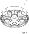
- a system 1 intended to be mounted on a surface is illustrated.
- the system 1 is a camera device which is intended to be mounted on a surface such as a ceiling.
- the system may be arranged for outdoor or indoor application.
- FIG. 2 some components of the system 1 shown in Fig. 1 are illustrated in an exploded view.
- the components comprise a mounting bracket 10, a plastic clamp 30, and an object 20 in the form of a camera unit.
- the mounting bracket 10 is configured for attachment to the surface and may for instance be provided with screw holes 11 enabling attachment of the mounting bracket 10 to the surface by means of screws.
- the mounting bracket 10 may be made of metal or plastic material. Metal material may be a preferred material for the mounting bracket in a system intended for outdoor application.
- the mounting bracket 10 is further provided with an opening 12 into which the plastic clamp 30 is insertable for mounting the plastic clamp 30 to the mounting bracket 10.
- the opening 12 may be provided in a peripheral portion 13 of the mounting bracket 10.
- the object 20 is attachable to the mounting bracket 10 by snap fit engagement with the plastic clamp 30 in its mounted state.
- the mounting bracket 10 is provided with an additional opening 12 configured for reception of an additional plastic clamp 30.
- the additional opening 12 may be provided in the peripheral portion 13 of the mounting bracket.
- the plastic clamp 30 and the additional plastic clamp 30 are oppositely arranged on the mounting bracket 10 when mounted thereto.
- the object 20 in the form of a camera unit is attachable to the mounting bracket 10 also by snap fit engagement with the additional plastic clamp 30.
- system 1 may comprise further additional plastic clamps mounted to the mounting bracket 10 and configured for snap fit engagement with the object 20.
- only one plastic clamp may be used for attachment of the object 20 to the mounting bracket 10.
- a part of the object 10 may be secured to the mounting bracket at a peripheral portion thereof opposite to the plastic clamp, whereafter the object may be pushed upwards such that the plastic clamp engages the object with a snap fit for attachment thereof to the mounting bracket.
- the system 1 may comprise additional objects which may be attached to the mounting bracket 10 by means of snap fit engagement with one or more plastic clamps mounted to the mounting bracket.
- Such an additional object may for instance be a dome window.
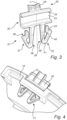
- a plastic clamp 30 for a system as disclosed above is shown.
- the plastic clamp 30 comprises a base part 31 and a connection part 32.
- the base part 31 is insertable into the opening 12 of the mounting bracket 10 for mounting of the plastic clamp 30 to the mounting bracket 10.
- connection part 32 is configured for snap fit engagement with the object 20 attachable to the mounting bracket 10. More specifically, the connection part 32 comprises a web 33 extending in a longitudinal direction L of the plastic clamp 30. The web 33 is provided with an upper protruding ridge 34. When the object 20 is attached to the mounting bracket 10, the upper protruding ridge 34 is configured to engage the object such that the connection part 32 is deflected for allowing the object 20 to be mounted with a snap fit.
- connection part 32 further comprises a tab 35 protruding from the connection part 32 in the longitudinal direction L of the plastic clamp 30.
- the tab 35 is arranged on top of the web 33.
- the tab 35 may be used for detachment of the object 20 from the mounting bracket 10. More specifically, the tab 35 may be manipulated for deflecting the connection part 32 of the plastic clamp 30 such that detachment of the object 20 is enabled.
- the base part 31 comprises two legs 36, each comprising a guide surface 37 and an L-shaped corner section 38. More specifically, each leg 36 comprises an elongated body having: a first portion 39 extending from the connection part 32 in the longitudinal direction L of the plastic clamp 30; a second portion 40 forming said guide surface 37, adjoining the first portion 39 and extending at an acute angle to the first portion 39 for forming a bend 41 at a front end of the leg 36; and a third portion 42 forming said L-shaped section 38 and adjoining the second portion 40.
- each leg 36 may have a reinforced transition section 43 between the first portion 39 and the second portion 40, i.e., in the bend 41 at the front end of the leg 36.
- Each guide surface 37 provided in the second portion 40 of each leg 36 is configured to engage the mounting bracket 10 in response to insertion of the base part 31 of the plastic clamp 30 into the opening 12 provided in the mounting bracket 10 such that the legs 36 are deflected for allowing snap fit mounting of the plastic clamp 30 to the mounting bracket 10.
- Each L-shaped corner section 38 formed by the third portion 42 of each leg 36 is configured to face a respective edge portion of the opening 12 of the mounting bracket 10 when the plastic clamp 30 is mounted to the mounting bracket 10.
- a plastic clamp 30 mounted to a mounting bracket 10 with a snap fit is illustrated. More specifically, the plastic clamp 30 has been mounted by insertion of the base part 31 into the opening 12 of the mounting bracket 10, which is disclosed more in detail in Figs. 5a , b.
- Fig. 5a the base part 31 of the plastic clamp 30 has been partly inserted into the opening 12, wherein the guide surface 37 of each leg 36 has engaged the mounting bracket 10 such that the legs 36 are deflected towards each other.
- the base part 31 has a base part width W3 in an affected state in which the legs 36 are deflected towards each other, which base part width W3 corresponds to an opening width W2 of the opening 12 of the mounting bracket 10.
- Fig. 5b the base part 31 has been fully inserted into the opening 12 of the mounting bracket 10, and the legs 36 have been allowed to assume original position, i.e., to deflect back, such that the plastic clamp 30 is snap fit mounted to the mounting bracket 10.
- the base part 31 In the mounted state of the plastic clamp 30, the base part 31 has a base part width W1 corresponding to an unaffected state, which unaffected base part width W1 is greater than the opening width W2 of the opening 12 of the mounting bracket 10.
- the L-shaped corner section 38 of each leg 36 of the base part 31 is configured to face a respective edge portion 14 of the opening 12 of the mounting bracket 10.
- the plastic clamp 30 is configured to prevent unintentional detachment from the mounting bracket 10. More specifically, the plastic clamp 30 is configured to prevent complete extraction of the base part 31 out of the opening 12 of the mounting bracket 10 in response to application of a pulling force to the plastic clamp 30, which now will be discussed with reference to Fig. 6 .
- each leg 36 comprises an L-shaped corner section 38 which in the mounted state of the plastic clamp 30 faces a respective edge portion 14 of the opening 12.
- the L-shaped corner sections 38 will engage the respective edge portions 14 causing the legs 36 to pivot about a respective axis defined by each L-shaped corner section 38 under elastic deformation of the legs 36.
- the legs 36 are, when pivoted about the respective axis under elastic deformation, configured to be brought to a state in which they abut each other such that further pivoting is restricted and thereby counteracting further extraction of the base part 31.
- the reinforced transition 43 section of each leg 36 facilitates controlled deformation of the legs 36 such that the state in which the legs 36 abut each other is achieved in a desired manner.
- the legs 36 of the base part 31 are thus configured to undergo controlled elastic deformation in response to application of a force P acting to extract the plastic clamp 30 out of the opening 12 of the mounting bracket 10 such that the legs 36 are brought to a state in which they abut each other, thereby counteracting further extraction.
- a force P acting to extract the plastic clamp 30 may be applied directly to the plastic clamp 30, or indirectly, for instance by applying a pulling force to the object attached to the mounting bracket.
- plastic clamp 30 may be intentionally detached from the mounting bracket 10 by pressing the legs 36 towards each other and subsequently pushing the base part 31 out of the opening 12 as illustrated in Figs. 7a , b.
Landscapes
- Engineering & Computer Science (AREA)
- General Engineering & Computer Science (AREA)
- Mechanical Engineering (AREA)
- Physics & Mathematics (AREA)
- General Physics & Mathematics (AREA)
- Multimedia (AREA)
- Signal Processing (AREA)
- Connection Of Plates (AREA)
- Insertion Pins And Rivets (AREA)
Abstract
Description
- The present invention relates to a plastic clamp for attachment of an object to a mounting bracket, as well as to a system intended to be mounted on a surface, which system comprises a mounting bracket configured for attachment to the surface.
- A system intended to be mounted on a surface often comprises a mounting bracket which is configured for attachment to the surface. Additional objects of the system may subsequently be releasably attached to the mounting bracket, such as by means of snap fit mounting.
- The system may for instance be a surveillance camera system in which objects in the form of a camera unit and a dome window are attached to and supported by the mounting bracket.
- The mounting bracket is often made of a strong and durable material, such as metal, which itself may not be suitable for snap fit mounting, and the mounting bracket may therefore be provided with plastic clamps enabling such snap fit mounting of one or more objects to the mounting bracket.
- It has proven difficult to provide such a system which is easy to assemble while also ensuring reliable releasable attachment of objects to the mounting bracket.
- In view of that stated above, it is an object of the present invention to provide an improved plastic clamp for attachment of an object to a mounting bracket.
- It is also an object to provide such a plastic clamp which is easy to mount to the mounting bracket and which enables reliable releasable attachment of an object to the mounting bracket.
- It is a further object to provide an improved system for mounting on a surface and comprising a mounting bracket and a plastic clamp.
- To achieve at least one of the above objects and also other objects that will be evident from the following description, a plastic clamp having the features defined in
claim 1 and a system having the features defined in claim 5 are provided according to the present invention. Preferred embodiments will be evident from the dependent claims. - More specifically, there is provided according to a first aspect of the present invention a plastic clamp for attachment of an object to a mounting bracket, the plastic clamp comprising a base part and a connection part, the base part being insertable into an opening of the mounting bracket for mounting of the plastic clamp to the mounting bracket and the connection part being configured for snap fit engagement with the object attachable to the mounting bracket, wherein the base part of the plastic clamp comprises two legs, wherein each leg comprises a guide surface and an L-shaped corner section, each guide surface being configured to engage the mounting bracket in response to insertion of the base part of the plastic clamp into the opening provided in the mounting bracket such that the legs are deflected for allowing snap fit mounting of the plastic clamp to the mounting bracket, each L-shaped corner section being configured to face a respective edge portion of the opening of the mounting bracket when the plastic clamp is mounted to the mounting bracket, wherein each leg of the base part comprises an elongated body having: a first portion extending from the connection part in a longitudinal direction of the plastic clamp; a second portion forming said guide surface, adjoining the first portion and extending at an acute angle to the first portion for forming a bend at a front end of the leg; and a third portion forming said L-shaped corner section and adjoining the second portion, and wherein the elongated body of each leg has a reinforced transition section between the first portion and the second portion.
- Hereby an improved plastic clamp for attachment of an object to a mounting bracket is provided.
- The base part of the plastic clamp comprises two legs each comprising an elongated body with a first portion extending from the connection part in a longitudinal direction of the plastic clamp, a second portion forming a guide surface, adjoining the first portion and extending at an acute angle to the first portion for forming a bend at a front end of the leg, and a third portion forming an L-shaped section and adjoining the second portion, wherein the elongated body of each leg has a reinforced transition section between the first portion and the second portion.
- Each guide surface is configured to engage the mounting bracket in response to insertion of the base part into the opening provided in the mounting bracket such that the legs are deflected for allowing snap fit mounting of the plastic clamp, thus enabling easy mounting of the plastic clamp.
- Each L-shaped corner section is configured to face a respective edge portion of the opening of the mounting bracket when the plastic clamp is mounted to the mounting bracket. The provision on L-shaped corner sections facing respective edge portions of the mounting bracket in combination with the reinforced transition sections enables reliable and releasable attachment of an object to the mounting bracket. More specifically, the configuration of the legs of the base part enables controlled elastic deformation of the base part in response to extraction of the base part out of the opening such that further extraction of the base part may be counteracted. Hereby unintentional detachment of the plastic clamp from the mounting bracket may be avoided.
- According to an embodiment, the elongated body of each leg may have an additional reinforced transition section between the second portion and the third portion. Hereby the elastic deformation of the base part may be further controlled in order to counteract further extraction.
- According to another embodiment, the base part may have a base part width W1 in an unaffected state, which base part width W1 is configured to be greater than an opening width W2 of the opening of the mounting bracket. Hereby, a secure snap fit mounting of the plastic clamp may be ensured.
- According to a further embodiment, the base part may have a base part width W3 in an affected state in which the legs are deflected towards each other, which base part width W3 is configured to correspond to the opening width W2 of the opening of the mounting bracket. Hereby snap fit mounting of the plastic clamp to the mounting bracket may be enabled.
- According to a further embodiment, the connection part of the plastic clamp may be provided with a tab protruding from the connection part in a longitudinal direction of the plastic clamp. The tab may be used for detachment of an object attached to the mounting bracket by snap fit engagement with the plastic clamp.
- According to a second aspect of the present invention, a system intended to be mounted on a surface is provided, the system comprising a mounting bracket configured for attachment to the surface, a plastic clamp having a base part and a connection part, wherein the mounting bracket is provided with an opening into which the base part of the plastic clamp is insertable with a snap fit for mounting of the plastic clamp to the mounting bracket, wherein the connection part of the plastic clamp is configured for snap fit engagement with an object attachable to the mounting bracket, wherein the base part of the plastic clamp comprises two legs, wherein each leg comprises a guide surface and an L-shaped corner section, the guide surface being configured to engage the mounting bracket in response to insertion of the base part of the plastic clamp into the opening and the L-shaped corner section being configured to face an edge portion of the opening when the base part of the plastic clamp has been received by the opening with a snap fit, wherein the legs are configured to be deflected in response to the guide surfaces engaging the mounting bracket such that the base part is insertable into the opening, wherein the L-shaped corner section of each leg is configured to, in a mounted state of the plastic clamp, engage the respective edge portion of the opening in response to extraction of the base part out of the opening such that the leg is pivoted about an axis defined by the L-shaped corner section under elastic deformation of the leg, and wherein the legs, when pivoted about the respective axis under elastic deformation, are configured to be brought to a state in which they abut each other such that further pivoting is restricted and thereby counteracting further extraction of the base part.
- Hereby an improved system intended to be mounted on a surface is provided. The system comprises a mounting bracket and a plastic clamp mountable to the mounting bracket and configured for snap fit attachment of an object to the mounting bracket. Thus, the mounting bracket may be made of a strong and durable material, such as metal, whereas the plastic clamp may be made of a plastic material enabling reliable snap fit attachment of the object to the mounting bracket.
- The plastic clamp comprises a base part comprising two legs, each being provided with a guide surface configured to engage the mounting bracket such that the legs are deflected when inserting the base part of the plastic clamp into the opening provided in the mounting bracket, whereby the base part is received by the opening with a snap fit. Hereby easy assembly of the system is ensured.
- Each leg of the plastic clamp may further comprise an L-shaped corner section which is configured to face an edge portion of the opening when the base part of the plastic clamp has been received by the opening with a snap fit. The L-shaped corner sections are configured to, in the mounted state of the plastic clamp, engage the edge portions of the opening in response to extraction of the base part out of the opening such that the leg is pivoted about an axis defined by the L-shaped corner section under elastic deformation of the leg. The legs are, when pivoted about the respective axis under elastic deformation, configured to be brought to a state in which they abut each other such that further pivoting is restricted and thereby counteracting further extraction of the base part. Thus, by controlling the elastic deformation of the legs such that they are brought to abut each other it is ensured that the plastic clamp cannot simply be drawn out of the opening of the mounting bracket. Hereby it is ensured that the system prevents unintentional detachment of the plastic clamp from the mounting bracket.
- According to an embodiment, each leg of the base part may comprise an elongated body having: a first portion extending from the connection part in a longitudinal direction of the plastic clamp; a second portion forming said guide surface, adjoining the first portion and extending at an acute angle to the first portion for forming a bend at a front end of the leg; and a third portion forming said L-shaped section and adjoining the second portion. Such a configuration may allow for efficient utilization of material when producing the plastic clamp.
- According to another embodiment, the elongated body of each leg may have a reinforced transition section between the first portion and the second portion. Hereby, the elastic deformation of the legs of the base part may be further controlled to ensure that the legs reliably abut each other in response to extraction of the base part out of the opening.
- According to a further embodiment, the base part may have a base part width W1 in an unaffected state, wherein the opening has an opening width W2 and wherein the base part width W1 in the unaffected state is greater than the opening width W2. Further, the base part may have a base part width W3 in an affected state in which the legs are deflected towards each other in response to insertion of the base part of the plastic clamp into the opening, wherein the opening has an opening width W2 and wherein the base part width W3 in the affected state corresponds to the opening width W2. Hereby snap fit mounting of the plastic clamp to the mounting bracket may be enabled.
- According to a further embodiment, the system may comprise an additional plastic clamp, wherein the mounting bracket is provided with an additional opening into which the base part of the additional plastic clamp is insertable with a snap fit for mounting of the additional plastic clamp to the mounting bracket. The provision of two plastic clamps may facilitate snap fit attachment of an object to the mounting bracket. The plastic clamp and the additional plastic clamp may be oppositely arranged on the mounting bracket when mounted thereto.
- According to a further embodiment, the opening of the mounting bracket may be provided in a peripheral portion thereof. Hereby easy access to the plastic clamp may be provided for attachment and detachment of an object to the mounting bracket.
- According to a further embodiment, the system may comprise an object attachable to the mounting bracket by snap fit engagement with the plastic clamp in its mounted state. The object may be a camera unit.
- According to a further embodiment, the mounting bracket may be made of a metal material.
- According to a further embodiment, the connection part of the plastic clamp may be provided with a tab protruding from the connection part in a longitudinal direction of the plastic clamp. The tab may be used for detachment of an object attached to the mounting bracket by snap fit engagement with the plastic clamp.
- Generally, all terms used in the claims are to be interpreted according to their ordinary meaning in the technical field, unless explicitly defined otherwise herein. All references to "a/an/the [element, device, component, means, step, etc.]" are to be interpreted openly as referring to at least one instance of said element, device, component, means, step, etc., unless explicitly stated otherwise. The steps of any method disclosed herein do not have to be performed in the exact order disclosed, unless explicitly stated.
- The above, as well as additional objects, features and advantages of the present invention, will be better understood through the following illustrative and non-limiting detailed description of preferred embodiments of the present invention, with reference to the appended drawings, where the same reference numerals will be used for similar elements, wherein:
-
Fig. 1 is a perspective view of a system intended to be mounted on a surface. -
Fig. 2 is a perspective view in exploded form illustrating a mounting bracket and an object in the form of a camera unit of a system intended to be mounted on a surface. -
Fig. 3 is a perspective view of a plastic clamp for attachment of an object to a mounting bracket. -
Fig. 4 is a perspective view of a plastic clamp mounted to a mounting bracket. -
Figs. 5a, b are schematic cross sectional views illustrating snap fit mounting of a plastic clamp to a mounting bracket. -
Fig. 6 is a schematic cross sectional view illustrating extraction of the plastic clamp shown inFig. 4 out of the mounting bracket. -
Figs. 7a, b are perspective views illustrating detachment of the plastic clamp shown inFig. 4 from the mounting bracket. - The present invention will now be described more fully hereinafter with reference to the accompanying drawings, in which currently preferred embodiments of the invention are shown. This invention may, however, be embodied in many different forms and should not be construed as limited to the embodiments set forth herein; rather, these embodiments are provided for thoroughness and completeness, and fully convey the scope of the invention to the skilled person.
- In
Fig. 1 , whereto reference is made, asystem 1 intended to be mounted on a surface is illustrated. In the shown embodiment, thesystem 1 is a camera device which is intended to be mounted on a surface such as a ceiling. The system may be arranged for outdoor or indoor application. - In
Fig. 2 , some components of thesystem 1 shown inFig. 1 are illustrated in an exploded view. The components comprise a mountingbracket 10, aplastic clamp 30, and anobject 20 in the form of a camera unit. - The mounting
bracket 10 is configured for attachment to the surface and may for instance be provided with screw holes 11 enabling attachment of the mountingbracket 10 to the surface by means of screws. - The mounting
bracket 10 may be made of metal or plastic material. Metal material may be a preferred material for the mounting bracket in a system intended for outdoor application. - The mounting
bracket 10 is further provided with anopening 12 into which theplastic clamp 30 is insertable for mounting theplastic clamp 30 to the mountingbracket 10. Theopening 12 may be provided in aperipheral portion 13 of the mountingbracket 10. - The
object 20 is attachable to the mountingbracket 10 by snap fit engagement with theplastic clamp 30 in its mounted state. - In the shown embodiment, the mounting
bracket 10 is provided with anadditional opening 12 configured for reception of anadditional plastic clamp 30. Theadditional opening 12 may be provided in theperipheral portion 13 of the mounting bracket. - The
plastic clamp 30 and theadditional plastic clamp 30 are oppositely arranged on the mountingbracket 10 when mounted thereto. - In the shown embodiment, the
object 20 in the form of a camera unit is attachable to the mountingbracket 10 also by snap fit engagement with theadditional plastic clamp 30. - It is understood that the
system 1 may comprise further additional plastic clamps mounted to the mountingbracket 10 and configured for snap fit engagement with theobject 20. - It is also understood that only one plastic clamp may be used for attachment of the
object 20 to the mountingbracket 10. For instance, a part of theobject 10 may be secured to the mounting bracket at a peripheral portion thereof opposite to the plastic clamp, whereafter the object may be pushed upwards such that the plastic clamp engages the object with a snap fit for attachment thereof to the mounting bracket. - The
system 1 may comprise additional objects which may be attached to the mountingbracket 10 by means of snap fit engagement with one or more plastic clamps mounted to the mounting bracket. Such an additional object may for instance be a dome window. - In
Fig. 3 , to which reference now is made, aplastic clamp 30 for a system as disclosed above is shown. - The
plastic clamp 30 comprises abase part 31 and aconnection part 32. - The
base part 31 is insertable into theopening 12 of the mountingbracket 10 for mounting of theplastic clamp 30 to the mountingbracket 10. - The
connection part 32 is configured for snap fit engagement with theobject 20 attachable to the mountingbracket 10. More specifically, theconnection part 32 comprises aweb 33 extending in a longitudinal direction L of theplastic clamp 30. Theweb 33 is provided with an upper protrudingridge 34. When theobject 20 is attached to the mountingbracket 10, the upper protrudingridge 34 is configured to engage the object such that theconnection part 32 is deflected for allowing theobject 20 to be mounted with a snap fit. - The
connection part 32 further comprises atab 35 protruding from theconnection part 32 in the longitudinal direction L of theplastic clamp 30. In the shown embodiment, thetab 35 is arranged on top of theweb 33. Thetab 35 may be used for detachment of theobject 20 from the mountingbracket 10. More specifically, thetab 35 may be manipulated for deflecting theconnection part 32 of theplastic clamp 30 such that detachment of theobject 20 is enabled. - The
base part 31 comprises twolegs 36, each comprising aguide surface 37 and an L-shapedcorner section 38. More specifically, eachleg 36 comprises an elongated body having: afirst portion 39 extending from theconnection part 32 in the longitudinal direction L of theplastic clamp 30; asecond portion 40 forming saidguide surface 37, adjoining thefirst portion 39 and extending at an acute angle to thefirst portion 39 for forming abend 41 at a front end of theleg 36; and athird portion 42 forming said L-shapedsection 38 and adjoining thesecond portion 40. - The elongated body of each
leg 36 may have a reinforcedtransition section 43 between thefirst portion 39 and thesecond portion 40, i.e., in thebend 41 at the front end of theleg 36. - Each
guide surface 37 provided in thesecond portion 40 of eachleg 36 is configured to engage the mountingbracket 10 in response to insertion of thebase part 31 of theplastic clamp 30 into theopening 12 provided in the mountingbracket 10 such that thelegs 36 are deflected for allowing snap fit mounting of theplastic clamp 30 to the mountingbracket 10. - Each L-shaped
corner section 38 formed by thethird portion 42 of eachleg 36 is configured to face a respective edge portion of theopening 12 of the mountingbracket 10 when theplastic clamp 30 is mounted to the mountingbracket 10. - In
Fig. 4 , to which reference now is made, aplastic clamp 30 mounted to a mountingbracket 10 with a snap fit is illustrated. More specifically, theplastic clamp 30 has been mounted by insertion of thebase part 31 into theopening 12 of the mountingbracket 10, which is disclosed more in detail inFigs. 5a , b. - In
Fig. 5a , thebase part 31 of theplastic clamp 30 has been partly inserted into theopening 12, wherein theguide surface 37 of eachleg 36 has engaged the mountingbracket 10 such that thelegs 36 are deflected towards each other. As evident from the figure, thebase part 31 has a base part width W3 in an affected state in which thelegs 36 are deflected towards each other, which base part width W3 corresponds to an opening width W2 of theopening 12 of the mountingbracket 10. - In
Fig. 5b , thebase part 31 has been fully inserted into theopening 12 of the mountingbracket 10, and thelegs 36 have been allowed to assume original position, i.e., to deflect back, such that theplastic clamp 30 is snap fit mounted to the mountingbracket 10. - In the mounted state of the
plastic clamp 30, thebase part 31 has a base part width W1 corresponding to an unaffected state, which unaffected base part width W1 is greater than the opening width W2 of theopening 12 of the mountingbracket 10. - In the mounted state of the
plastic clamp 30, the L-shapedcorner section 38 of eachleg 36 of thebase part 31 is configured to face arespective edge portion 14 of theopening 12 of the mountingbracket 10. - The
plastic clamp 30 is configured to prevent unintentional detachment from the mountingbracket 10. More specifically, theplastic clamp 30 is configured to prevent complete extraction of thebase part 31 out of theopening 12 of the mountingbracket 10 in response to application of a pulling force to theplastic clamp 30, which now will be discussed with reference toFig. 6 . - As mentioned above, each
leg 36 comprises an L-shapedcorner section 38 which in the mounted state of theplastic clamp 30 faces arespective edge portion 14 of theopening 12. When a pulling force P is applied to theplastic clamp 30 acting to try to extract theplastic clamp 30 out of theopening 12, the L-shapedcorner sections 38 will engage therespective edge portions 14 causing thelegs 36 to pivot about a respective axis defined by each L-shapedcorner section 38 under elastic deformation of thelegs 36. Thelegs 36 are, when pivoted about the respective axis under elastic deformation, configured to be brought to a state in which they abut each other such that further pivoting is restricted and thereby counteracting further extraction of thebase part 31. The reinforcedtransition 43 section of eachleg 36 facilitates controlled deformation of thelegs 36 such that the state in which thelegs 36 abut each other is achieved in a desired manner. - The
legs 36 of thebase part 31 are thus configured to undergo controlled elastic deformation in response to application of a force P acting to extract theplastic clamp 30 out of theopening 12 of the mountingbracket 10 such that thelegs 36 are brought to a state in which they abut each other, thereby counteracting further extraction. Hereby, unintentional detachment of theplastic clamp 30 from the mountingbracket 10 may be prevented. The application of a force P acting to extract theplastic clamp 30 may be applied directly to theplastic clamp 30, or indirectly, for instance by applying a pulling force to the object attached to the mounting bracket. - It is understood that the
plastic clamp 30 may be intentionally detached from the mountingbracket 10 by pressing thelegs 36 towards each other and subsequently pushing thebase part 31 out of theopening 12 as illustrated inFigs. 7a , b. - It will be appreciated that the present invention is not limited to the embodiments shown. Several modifications and variations are thus conceivable within the scope of the invention which thus is exclusively defined by the appended claims.
Claims (16)
- A plastic clamp for attachment of an object (20) to a mounting bracket (10), the plastic clamp comprisinga base part (31) and a connection part (32), the base part (31) being insertable into an opening (12) of the mounting bracket (10) for mounting of the plastic clamp to the mounting bracket (10) and the connection part (32) being configured for snap fit engagement with the object (20) attachable to the mounting bracket (10),wherein the base part (31) of the plastic clamp comprises two legs (36),wherein each leg (36) comprises a guide surface (37) and an L-shaped corner section (38),each guide surface (37) being configured to engage the mounting bracket (10) in response to insertion of the base part (31) of the plastic clamp into the opening (12) provided in the mounting bracket (10) such that the legs (36) are deflected for allowing snap fit mounting of the plastic clamp to the mounting bracket (10),each L-shaped corner section (38) being configured to face a respective edge portion (14) of the opening (12) of the mounting bracket (10) when the plastic clamp is mounted to the mounting bracket (10),wherein each leg (36) of the base part (31) comprises an elongated body having: a first portion (39) extending from the connection part (32) in a longitudinal direction L of the plastic clamp; a second portion (40) forming said guide surface (37), adjoining the first portion (39) and extending at an acute angle to the first portion (39) for forming a bend (41) at a front end of the leg (36); and a third portion (42) forming said L-shaped corner section (38) and adjoining the second portion (40), andwherein the elongated body of each leg (36) has a reinforced transition section (43) between the first portion (39) and the second portion (40).
- The plastic clamp according to claim 1, wherein the base part (31) has a base part width W1 in an unaffected state, which base part width W1 is configured to be greater than an opening width W2 of the opening (12) of the mounting bracket (10).
- The plastic clamp according to any claim 1 or 2, wherein the base part (31) has a base part width W3 in an affected state in which the legs (36) are deflected towards each other, which base part width W3 is configured to correspond to an opening width W2 of the opening (12) of the mounting bracket (10).
- The plastic clamp according to any one of claims 1-3, wherein the connection part (31) of the plastic clamp is provided with a tab (35) protruding from the connection part (31) in a longitudinal direction L of the plastic clamp.
- A system intended to be mounted on a surface, the system comprisinga mounting bracket (10) configured for attachment to the surface,a plastic clamp (30) having a base part (31) and a connection part (32),wherein the mounting bracket (10) is provided with an opening (12) into which the base part (31) of the plastic clamp (30) is insertable with a snap fit for mounting of the plastic clamp (30) to the mounting bracket (10),wherein the connection part (32) of the plastic clamp (30) is configured for snap fit engagement with an object (20) attachable to the mounting bracket (10),wherein the base part (31) of the plastic clamp (30) comprises two legs (36),wherein each leg (36) comprises a guide surface (37) and an L-shaped corner section (38), the guide surface (37) being configured to engage the mounting bracket (10) in response to insertion of the base part (31) of the plastic clamp (30) into the opening (12) and the L-shaped corner section (38) being configured to face an edge portion (14) of the opening (12) when the base part (31) of the plastic clamp (30) has been received by the opening (12) with a snap fit,wherein the legs (36) are configured to be deflected in response to the guide surfaces (37) engaging the mounting bracket (10) such that the base part (31) is insertable into the opening (12),wherein the L-shaped corner section (38) of each leg (36) is configured to, in a mounted state of the plastic clamp (30), engage the respective edge portion (14) of the opening (12) in response to extraction of the base part (31) out of the opening (12) such that the leg (36) is pivoted about an axis defined by the L-shaped corner section (38) under elastic deformation of the leg (36), andwherein the legs (36), when pivoted about the respective axis under elastic deformation, are configured to be brought to a state in which they abut each other such that further pivoting is restricted and thereby counteracting further extraction of the base part (31).
- The system according to claim 5, wherein each leg (36) of the base part (31) comprises an elongated body having: a first portion (39) extending from the connection part (31) in a longitudinal direction L of the plastic clamp (30); a second portion (40) forming said guide surface (37), adjoining the first portion (39) and extending at an acute angle to the first portion (39) for forming a bend (41) at a front end of the leg (36); and a third portion (42) forming said L-shaped corner section (38) and adjoining the second portion (40).
- The system according to claim 6, wherein the elongated body of each leg (36) has a reinforced transition section (43) between the first portion (39) and the second portion (40).
- The system according to any one of claims 5-7, wherein the base part (31) has a base part width W1 in an unaffected state and wherein the opening (12) has an opening width W2, wherein the base part width W1 in the unaffected state is greater than the opening width W2.
- The system according to any one of claims 5-8, wherein the base part (31) has a base part width W3 in an affected state in which the legs (36) are deflected towards each other in response to insertion of the base part (31) of the plastic clamp (30) into the opening (12) and wherein the opening (12) has an opening width W2, wherein the base part width W3 in the affected state corresponds to the opening width W2.
- The system according to any one of claims 5-9, further comprising an additional plastic clamp (30), wherein the mounting bracket (10) is provided with an additional opening (12) into which the base part (31) of the additional plastic clamp (30) is insertable with a snap fit for mounting of the additional plastic clamp (30) to the mounting bracket (10).
- The system according to claim 10, wherein the plastic clamp (30) and the additional plastic clamp (30) are oppositely arranged on the mounting bracket (10) when mounted thereto.
- The system according to any one of claims 5-11, wherein the opening (12) of the mounting bracket (10) is provided in a peripheral portion (13) thereof.
- The system according to any one of claims 5-12, further comprising an object (20) attachable to the mounting bracket (10) by snap fit engagement with the plastic clamp (30) in its mounted state.
- The system according to claim 13, wherein the object (20) is a camera unit.
- The system according to any one of claims 5-14, wherein the mounting bracket (10) is made of a metal material.
- The system according to any one of claims 5-15, wherein the connection part (32) of the plastic clamp (30) is provided with a tab (35) protruding from the connection part (32) in a longitudinal direction L of the plastic clamp (30).
Priority Applications (4)
| Application Number | Priority Date | Filing Date | Title |
|---|---|---|---|
| EP23175787.3A EP4467822B1 (en) | 2023-05-26 | 2023-05-26 | Plastic clamp and system for mounting on a surface |
| KR1020240045984A KR103005857B1 (en) | 2023-05-26 | 2024-04-04 | System for mounting on a surface |
| US18/634,116 US12488666B2 (en) | 2023-05-26 | 2024-04-12 | System for mounting on a surface |
| CN202410615090.9A CN119022204B (en) | 2023-05-26 | 2024-05-17 | Systems for mounting on a surface |
Applications Claiming Priority (1)
| Application Number | Priority Date | Filing Date | Title |
|---|---|---|---|
| EP23175787.3A EP4467822B1 (en) | 2023-05-26 | 2023-05-26 | Plastic clamp and system for mounting on a surface |
Publications (3)
| Publication Number | Publication Date |
|---|---|
| EP4467822A1 true EP4467822A1 (en) | 2024-11-27 |
| EP4467822C0 EP4467822C0 (en) | 2025-10-29 |
| EP4467822B1 EP4467822B1 (en) | 2025-10-29 |
Family
ID=86692814
Family Applications (1)
| Application Number | Title | Priority Date | Filing Date |
|---|---|---|---|
| EP23175787.3A Active EP4467822B1 (en) | 2023-05-26 | 2023-05-26 | Plastic clamp and system for mounting on a surface |
Country Status (3)
| Country | Link |
|---|---|
| US (1) | US12488666B2 (en) |
| EP (1) | EP4467822B1 (en) |
| CN (1) | CN119022204B (en) |
Citations (5)
| Publication number | Priority date | Publication date | Assignee | Title |
|---|---|---|---|---|
| US6234691B1 (en) * | 1998-06-15 | 2001-05-22 | Philips Electronics North America Corporation | Apparatus for mounting a surveillance camera |
| US7217045B2 (en) * | 2005-01-03 | 2007-05-15 | Robert Bosch Gmbh | Connect/disconnect mechanism for a surveillance camera head |
| US20170030389A1 (en) * | 2015-06-30 | 2017-02-02 | Penn Engineering & Manufacturing Corp. | Clamping Snap-In Fastener |
| US20170297506A1 (en) * | 2016-04-18 | 2017-10-19 | Ford Global Technologies, Llc | W-shaped winged spring clip |
| US20180291942A1 (en) * | 2017-04-06 | 2018-10-11 | Newfrey Llc | Clip |
Family Cites Families (12)
| Publication number | Priority date | Publication date | Assignee | Title |
|---|---|---|---|---|
| JP4977908B2 (en) | 2007-08-30 | 2012-07-18 | ポップリベット・ファスナー株式会社 | Anchor type clip |
| GB0909984D0 (en) | 2009-06-11 | 2009-07-22 | Rolls Royce Plc | Fastener |
| DE202010012226U1 (en) | 2010-09-06 | 2011-12-07 | Dieter Ramsauer | fastening device |
| EP2789931B1 (en) * | 2013-04-12 | 2020-08-12 | Renusol Europe GmbH | Holding apparatus for fixing a surface module to a support |
| DE102015106223B4 (en) * | 2015-04-22 | 2024-09-12 | Illinois Tool Works Inc. | System for attaching a door module to an automobile door |
| JP2017141940A (en) | 2016-02-12 | 2017-08-17 | 住友電装株式会社 | Anchor clip structure and band clip |
| DE202016104408U1 (en) * | 2016-08-10 | 2017-11-13 | Böllhoff Verbindungstechnik GmbH | mounting clip |
| US10100857B2 (en) * | 2016-09-01 | 2018-10-16 | Ford Global Technologies, Llc | W-shaped winged spring clip with at least one reinforcing gusset |
| DE102016014628A1 (en) | 2016-12-09 | 2018-06-14 | A.RAYMOND et Cie. SCS | Clip for attaching a first element to a second element |
| US10436233B2 (en) * | 2017-09-07 | 2019-10-08 | Ford Global Technologies, Llc | Spring clip with frangible features indicating correct installation |
| EP3514436B1 (en) * | 2018-01-17 | 2019-12-11 | Axis AB | A fastening arrangement, a fastening arrangement kit and use of a fastening arrangement kit |
| FR3079890B1 (en) | 2018-04-04 | 2020-04-03 | A. Raymond Et Cie | FIXING CLIP FOR PHOTOVOLTAIC CHASSIS WITH INSERTION MOUNTING THEN SLIDING IN A SLOT OF A SUPPORT WALL |
-
2023
- 2023-05-26 EP EP23175787.3A patent/EP4467822B1/en active Active
-
2024
- 2024-04-12 US US18/634,116 patent/US12488666B2/en active Active
- 2024-05-17 CN CN202410615090.9A patent/CN119022204B/en active Active
Patent Citations (5)
| Publication number | Priority date | Publication date | Assignee | Title |
|---|---|---|---|---|
| US6234691B1 (en) * | 1998-06-15 | 2001-05-22 | Philips Electronics North America Corporation | Apparatus for mounting a surveillance camera |
| US7217045B2 (en) * | 2005-01-03 | 2007-05-15 | Robert Bosch Gmbh | Connect/disconnect mechanism for a surveillance camera head |
| US20170030389A1 (en) * | 2015-06-30 | 2017-02-02 | Penn Engineering & Manufacturing Corp. | Clamping Snap-In Fastener |
| US20170297506A1 (en) * | 2016-04-18 | 2017-10-19 | Ford Global Technologies, Llc | W-shaped winged spring clip |
| US20180291942A1 (en) * | 2017-04-06 | 2018-10-11 | Newfrey Llc | Clip |
Also Published As
| Publication number | Publication date |
|---|---|
| KR20240170398A (en) | 2024-12-03 |
| EP4467822C0 (en) | 2025-10-29 |
| US20240395122A1 (en) | 2024-11-28 |
| EP4467822B1 (en) | 2025-10-29 |
| US12488666B2 (en) | 2025-12-02 |
| CN119022204B (en) | 2026-02-24 |
| CN119022204A (en) | 2024-11-26 |
Similar Documents
| Publication | Publication Date | Title |
|---|---|---|
| US12537475B2 (en) | Roof attachment system and apparatus | |
| US7424993B2 (en) | Combination spring tension rod and mounting brackets for window coverings | |
| CN100458192C (en) | Device for connecting a support and an accessory | |
| US5966893A (en) | Clip for retaining adjacent panels in a planar relationship | |
| US6931794B1 (en) | Method and apparatus for installing fitting | |
| EP1703584A1 (en) | Vehicle roof antenna mounting assembly | |
| US5765312A (en) | Access panel incorporating a spring clamping device | |
| US6605776B1 (en) | Mounting assembly for an electrical distribution block in modular office furniture | |
| JP2023053948A (en) | Mounting device with fastener receiving structure | |
| EP4467822B1 (en) | Plastic clamp and system for mounting on a surface | |
| CA2060059C (en) | Angled connection of suspended ceiling tees | |
| EP3430213A1 (en) | Mounting clip for building boards | |
| WO2024219969A1 (en) | System for attaching a wind deflector to a solar panel | |
| CN211601164U (en) | Cable protection mechanism and pan-tilt camera thereof | |
| JP3891242B2 (en) | Support and wiring equipment | |
| EP1944847A2 (en) | Installation box with removable mounting device | |
| US20070090246A1 (en) | Combination spring tension rod and mounting brackets for window coverings | |
| JP3332671B2 (en) | Fixture fixture and lighting fixture using the same | |
| CN211575492U (en) | Air conditioner panel with reserved mounting hole | |
| CN220014937U (en) | Adjust movable buckle structure and screen window | |
| CN214658434U (en) | Buckle plate connecting structure | |
| CN220621516U (en) | Hinge for power distribution cabinet and power distribution cabinet | |
| CN215175897U (en) | Air conditioner cover and air conditioner | |
| KR102305338B1 (en) | Fixing apparatus for wall pad | |
| SK5899A3 (en) | Covering for radiators |
Legal Events
| Date | Code | Title | Description |
|---|---|---|---|
| PUAI | Public reference made under article 153(3) epc to a published international application that has entered the european phase |
Free format text: ORIGINAL CODE: 0009012 |
|
| STAA | Information on the status of an ep patent application or granted ep patent |
Free format text: STATUS: REQUEST FOR EXAMINATION WAS MADE |
|
| 17P | Request for examination filed |
Effective date: 20240313 |
|
| AK | Designated contracting states |
Kind code of ref document: A1 Designated state(s): AL AT BE BG CH CY CZ DE DK EE ES FI FR GB GR HR HU IE IS IT LI LT LU LV MC ME MK MT NL NO PL PT RO RS SE SI SK SM TR |
|
| GRAP | Despatch of communication of intention to grant a patent |
Free format text: ORIGINAL CODE: EPIDOSNIGR1 |
|
| STAA | Information on the status of an ep patent application or granted ep patent |
Free format text: STATUS: GRANT OF PATENT IS INTENDED |
|
| RIC1 | Information provided on ipc code assigned before grant |
Ipc: F16B 2/22 20060101AFI20250724BHEP Ipc: F16B 21/08 20060101ALI20250724BHEP Ipc: H04N 23/51 20230101ALI20250724BHEP Ipc: G08B 13/196 20060101ALI20250724BHEP Ipc: G03B 17/56 20210101ALI20250724BHEP |
|
| INTG | Intention to grant announced |
Effective date: 20250807 |
|
| GRAS | Grant fee paid |
Free format text: ORIGINAL CODE: EPIDOSNIGR3 |
|
| GRAA | (expected) grant |
Free format text: ORIGINAL CODE: 0009210 |
|
| STAA | Information on the status of an ep patent application or granted ep patent |
Free format text: STATUS: THE PATENT HAS BEEN GRANTED |
|
| AK | Designated contracting states |
Kind code of ref document: B1 Designated state(s): AL AT BE BG CH CY CZ DE DK EE ES FI FR GB GR HR HU IE IS IT LI LT LU LV MC ME MK MT NL NO PL PT RO RS SE SI SK SM TR |
|
| REG | Reference to a national code |
Ref country code: CH Ref legal event code: F10 Free format text: ST27 STATUS EVENT CODE: U-0-0-F10-F00 (AS PROVIDED BY THE NATIONAL OFFICE) Effective date: 20251029 Ref country code: GB Ref legal event code: FG4D |
|
| REG | Reference to a national code |
Ref country code: IE Ref legal event code: FG4D |
|
| U01 | Request for unitary effect filed |
Effective date: 20251029 |
|
| U07 | Unitary effect registered |
Designated state(s): AT BE BG DE DK EE FI FR IT LT LU LV MT NL PT RO SE SI Effective date: 20251104 |
|
| PG25 | Lapsed in a contracting state [announced via postgrant information from national office to epo] |
Ref country code: ES Free format text: LAPSE BECAUSE OF FAILURE TO SUBMIT A TRANSLATION OF THE DESCRIPTION OR TO PAY THE FEE WITHIN THE PRESCRIBED TIME-LIMIT Effective date: 20251029 |
|
| PG25 | Lapsed in a contracting state [announced via postgrant information from national office to epo] |
Ref country code: NO Free format text: LAPSE BECAUSE OF FAILURE TO SUBMIT A TRANSLATION OF THE DESCRIPTION OR TO PAY THE FEE WITHIN THE PRESCRIBED TIME-LIMIT Effective date: 20260129 |
|
| PG25 | Lapsed in a contracting state [announced via postgrant information from national office to epo] |
Ref country code: HR Free format text: LAPSE BECAUSE OF FAILURE TO SUBMIT A TRANSLATION OF THE DESCRIPTION OR TO PAY THE FEE WITHIN THE PRESCRIBED TIME-LIMIT Effective date: 20251029 |
|
| PG25 | Lapsed in a contracting state [announced via postgrant information from national office to epo] |
Ref country code: RS Free format text: LAPSE BECAUSE OF FAILURE TO SUBMIT A TRANSLATION OF THE DESCRIPTION OR TO PAY THE FEE WITHIN THE PRESCRIBED TIME-LIMIT Effective date: 20260129 |
|
| PG25 | Lapsed in a contracting state [announced via postgrant information from national office to epo] |
Ref country code: IS Free format text: LAPSE BECAUSE OF FAILURE TO SUBMIT A TRANSLATION OF THE DESCRIPTION OR TO PAY THE FEE WITHIN THE PRESCRIBED TIME-LIMIT Effective date: 20260228 |
|
| PG25 | Lapsed in a contracting state [announced via postgrant information from national office to epo] |
Ref country code: PL Free format text: LAPSE BECAUSE OF FAILURE TO SUBMIT A TRANSLATION OF THE DESCRIPTION OR TO PAY THE FEE WITHIN THE PRESCRIBED TIME-LIMIT Effective date: 20251029 |
|
| U20 | Renewal fee for the european patent with unitary effect paid |
Year of fee payment: 4 Effective date: 20260421 |
|
| PG25 | Lapsed in a contracting state [announced via postgrant information from national office to epo] |
Ref country code: SM Free format text: LAPSE BECAUSE OF FAILURE TO SUBMIT A TRANSLATION OF THE DESCRIPTION OR TO PAY THE FEE WITHIN THE PRESCRIBED TIME-LIMIT Effective date: 20251029 |
|
| PG25 | Lapsed in a contracting state [announced via postgrant information from national office to epo] |
Ref country code: CZ Free format text: LAPSE BECAUSE OF FAILURE TO SUBMIT A TRANSLATION OF THE DESCRIPTION OR TO PAY THE FEE WITHIN THE PRESCRIBED TIME-LIMIT Effective date: 20251029 |
|
| PG25 | Lapsed in a contracting state [announced via postgrant information from national office to epo] |
Ref country code: SK Free format text: LAPSE BECAUSE OF FAILURE TO SUBMIT A TRANSLATION OF THE DESCRIPTION OR TO PAY THE FEE WITHIN THE PRESCRIBED TIME-LIMIT Effective date: 20251029 |