EP4467421A1 - Steering device - Google Patents
Steering device Download PDFInfo
- Publication number
- EP4467421A1 EP4467421A1 EP24175340.9A EP24175340A EP4467421A1 EP 4467421 A1 EP4467421 A1 EP 4467421A1 EP 24175340 A EP24175340 A EP 24175340A EP 4467421 A1 EP4467421 A1 EP 4467421A1
- Authority
- EP
- European Patent Office
- Prior art keywords
- pair
- portions
- column
- bolt
- support
- Prior art date
- Legal status (The legal status is an assumption and is not a legal conclusion. Google has not performed a legal analysis and makes no representation as to the accuracy of the status listed.)
- Granted
Links
Images




Classifications
-
- B—PERFORMING OPERATIONS; TRANSPORTING
- B62—LAND VEHICLES FOR TRAVELLING OTHERWISE THAN ON RAILS
- B62D—MOTOR VEHICLES; TRAILERS
- B62D1/00—Steering controls, i.e. means for initiating a change of direction of the vehicle
- B62D1/02—Steering controls, i.e. means for initiating a change of direction of the vehicle vehicle-mounted
- B62D1/16—Steering columns
- B62D1/18—Steering columns yieldable or adjustable, e.g. tiltable
- B62D1/184—Mechanisms for locking columns at selected positions
-
- B—PERFORMING OPERATIONS; TRANSPORTING
- B62—LAND VEHICLES FOR TRAVELLING OTHERWISE THAN ON RAILS
- B62D—MOTOR VEHICLES; TRAILERS
- B62D1/00—Steering controls, i.e. means for initiating a change of direction of the vehicle
- B62D1/02—Steering controls, i.e. means for initiating a change of direction of the vehicle vehicle-mounted
- B62D1/16—Steering columns
- B62D1/18—Steering columns yieldable or adjustable, e.g. tiltable
- B62D1/187—Steering columns yieldable or adjustable, e.g. tiltable with tilt adjustment; with tilt and axial adjustment
-
- B—PERFORMING OPERATIONS; TRANSPORTING
- B62—LAND VEHICLES FOR TRAVELLING OTHERWISE THAN ON RAILS
- B62D—MOTOR VEHICLES; TRAILERS
- B62D1/00—Steering controls, i.e. means for initiating a change of direction of the vehicle
- B62D1/02—Steering controls, i.e. means for initiating a change of direction of the vehicle vehicle-mounted
- B62D1/16—Steering columns
- B62D1/18—Steering columns yieldable or adjustable, e.g. tiltable
- B62D1/187—Steering columns yieldable or adjustable, e.g. tiltable with tilt adjustment; with tilt and axial adjustment
- B62D1/189—Steering columns yieldable or adjustable, e.g. tiltable with tilt adjustment; with tilt and axial adjustment the entire column being tiltable as a unit
Definitions
- the present invention relates to a steering device in which a steering shaft is expandable and tiltable.
- the steering device disclosed in JP S59-128054 A comprises a cylindrical support column to support the expandable steering shaft, which is comprised of an upper jacket and a lower jacket which are engaged with each other, a support bracket with a pair of side wall portions to support the upper and lower jackets at a vehicle body in a tiltable manner, and a reinforcement bracket arranged between each of the pair of side wall portions and the upper and lower jackets so as to press the upper and lower jackets from both sides, in a vehicle width direction, thereof by a fastening force of a bolt.
- the reinforcement bracket is a roughly U-shaped plate member to cover a lower half of the upper and lower jackets and has a pair of pressing portions facing to each other.
- the fastening force of the bolt makes a distance between the pair of pressing portions of the reinforcement narrower, thereby pressing the lower half of the upper and lower jackets engaged with each other toward an inward side from an outward side, in the vehicle width direction, thereof, so that the upper and lower jackets can be fixed at the desired length and angle.
- the present invention has been devised in view of the above-described matter, and an object of the present invention is to provide a steering device which can properly fix a steering column supporting a steering shaft at the high fastening rigidity and conduct the tilting and axial moving of a steering column smoothly in the event of releasing the bolt's fastening.
- the steering device of the present invention comprises an upper shaft extending in a vehicle longitudinal direction and having a rear end portion to which a steering wheel is fixed, an upper column rotatably supporting the upper shaft, a lower shaft connected to a front end portion of the upper shaft so as to slide in an axial direction, a lower column rotatably supporting the lower shaft and provided to be movable in an axial direction relative to the upper column, a support bracket fixed to a vehicle body and supporting a support-side column which is either one of the lower column and the upper column, and a tilt-telescopic mechanism operative to switch a state of the support-side column between a movable state where the support-side column is allowed to tilt in a vertical direction and move in an axial direction and a prohibited state where the support-side column's tilting and moving is prohibited, wherein the tilt-telescopic mechanism includes a pair of side wall portions provided at the support bracket to interpose the support-side column therebetween from both sides in a vehicle width direction and having tilting long holes extending
- either one of the upper column and the lower column is supported at the support bracket as the support-side column, and the state of the support-side column is switched, by the tilt-telescopic mechanism, between the movable state where the support-side column is allowed to tilt in the vertical direction and move in the axial direction and the prohibited state where the support-side column's tilting and moving is prohibited.
- the tilt-telescopic mechanism comprises the biasing member which is arranged between each of the pair of side wall portions of the support bracket and the support-side column so as to apply the pressing force to the support-side column from the both sides, in the vehicle width direction, thereof when the pair of side wall portions receive the fastening force.
- the above-described biasing member comprises at least the pair of upper-side pressing portions pressing the portion of the support-side column which is above its axial center from the both sides, in the vehicle width direction, thereof and at least the pair of lower-side pressing portions pressing another portion of the support-side column which is below its axial center from the both sides, in the vehicle width direction, thereof.
- the support-side column comes to be restrained at four separated points, in a peripheral direction, thereof in its axial-direction view. Consequently, the support-side column can be fixed at the properly-high fastening rigidity between the pair of the side wall portions.
- the bolt operational portion be a lever operative to change the fastening force of the bolt inserted into the tilting long holes
- this lever comprise a root-side end portion connected to the bolt and an operational-side end portion positioned on a vehicle rearward side of the bolt and operative to receive an operational force from outside, and the pair of upper-side pressing portions and the pair of lower-side pressing portions be arranged on the vehicle rearward side of the tilting long holes.
- the pair of upper-side pressing portions and the pair of lower-side pressing portions of the biasing member are arranged on the vehicle rearward side of a position of the bolt inserted into the tilting long holes, a position of a connection portion where the root-side end portion of the lever (the bolt operational portion) is connected to the bolt can be shifted toward a vehicle forward side from a position of the upper-side pressing portion and the lower-side pressing portion which fix the support-side column.
- the length of the lever can be properly long without changing a longitudinal position of the operational-side end portion of the lever.
- the fastening force of the bolt can be properly large without increasing the operational force applied to the operational-side end portion. Consequently, the operability of the lever can improve.
- the pair of upper-side pressing portions and the pair of lower-side pressing portions be arranged on forward-and-rearward both sides, in the vehicle longitudinal direction, of the tilting long holes, respectively.
- the pair of upper-side pressing portions and the pair of lower-side pressing portions of the biasing member are respectively arranged at two separated points, in the longitudinal direction, thereof in such a manner they enclose the tilting long holes formed at the side wall portions in a vehicle-width-direction view. Therefore, the pair of side wall portions can stably fix the support-side column by supporting at the front-and-rear two points of the upper-side pressing portion and the front-and-rear two points of the lower-side pressing portion which enclose the tilting long holes in the vehicle-width-direction view, i.e., at a total of four points of the pressing portions.
- the steering device further comprise a pair of pressing plates arranged on respective outward sides, in the vehicle width direction, of the pair of side wall portions and operative to press the pair of side wall portions to respective inward sides, in the vehicle width direction, thereof when receiving the fastening force of the bolt, and the pair of pressing plates have respective convex portions which protrude toward the side wall portions at respective positions which face the pair of upper-side pressing portions and the pair of lower-side pressing portions, interposing the side wall portions therebetween.
- the convex portions can press the upper-side pressing portions and the lower-side pressing portions of the biasing member via the side wall portions.
- the fastening force of the bolt can be effectively transmitted to the upper-side pressing portions and the lower-side pressing portions of the biasing member.
- the support-side column pressed by the pair of upper-side pressing portions and the pair of lower-side pressing portions of the biasing member can be stably fixed between the pair of side wall portions.
- the support bracket further comprise a support-bracket connection portion to interconnect the pair of side wall portions, and the support-bracket connection portion have a bending deformation portion operative to be bending-deformed in a direction where the pair of side wall portions approach each other when the pair of side wall portions receive the fastening force of the bolt.
- the support-bracket connection portion interconnecting the pair of side wall portions has the bending deformation portion
- the pair of side wall portions can be made close to each other due to bending deformation of the bending-deformation portion when receiving the fastening force of the bolt.
- the fastening force of the bolt can be uniformly transmitted to the pair of upper-side pressing portions and the pair of lower-side pressing portions of the biasing member arranged between the side wall potions and the support-side column. Consequently, the support-side column pressed by the pair of upper-side pressing portions and the pair of lower-side pressing portions of the biasing member can be stably fixed between the pair of side wall portions.
- the biasing member further have a pair of support portions extending in the vehicle longitudinal direction and supporting the pair of upper-side pressing portions and the pair of lower-side pressing portions, respectively, and a biasing-member connection portion to interconnect vehicle-forward-side end portions of the pair of support portions, and the pair of support portions be configured to be bending-deformed toward an inward side, in the vehicle width direction, thereof when the pair of upper-side pressing portions and the pair of lower-side pressing portions receive the fastening force of the bolt.
- the steering device of the present invention can properly fix the column to support the shaft at the high fastening rigidity and conduct the tilting and axial moving of the column smoothly in the event of releasing the bolt's fastening.
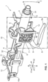
- a steering device 1 of the present embodiment shown in FIGS. 1 - 6 is arranged along a vehicle longitudinal direction X in such a manner that it protrudes toward a cabin inside from an engine room provided in a vehicle body of an automotive vehicle, which is used as the steering device of a vehicle.
- This steering device 1 is configured such that a steering shaft composed of an upper shaft 2 and a lower shaft 4 is configured to be expandable and tiltable and also be fixable at the desired length and angle.
- the steering device 1 comprises the upper shaft 2, an upper column 3 which rotatably supports the upper shaft 2, the lower shaft 4 which is connected to a front end portion (an end portion at a vehicle forward side X1) of the upper shaft 2 so as to slide in an axial direction, a lower column portion 11 (lower column) which rotatably supports the lower shaft 4 and includes an upper-column biasing portion 12 (biasing member), a support bracket 6 which supports the upper column 3, a pair of pressing plates 7 which are arranged on both sides, in a vehicle width direction Y, of the support bracket 6, a bolt 9 and a nut 14 which are together operative to fasten the support bracket 6 and the pair of pressing plates 7 from respective outward sides, in the vehicle width direction Y, thereof, a lever 8 as a bolt operational portion which is connected to a head-side portion of the bolt 9 and operative to change a fastening force of the bolt 9 by rotating the bolt 9, and an outer-column support bracket 13 which supports so that the outer column 5 can tilt
- the bolt 9 can be fastened or released by a driver's operation of the lever 8.
- the lever 8 is specifically configured such that a cam 18 attached to the bolt 9 is rotatably operated so as to ride up and down, thereby changing a state where the fastening force of bolt 9 is generated or not.
- the support bracket 6 and the outer-column support bracket 13 are fixed at the vehicle body by bolts or the like.
- the upper shaft 2, the upper column 3, the lower shaft 4, the outer column 5, and the pair of pressing plates 7 are made tiltable in the vertical direction Z around a support axis 13a of the outer-column support bracket 13 (see a tilt direction T shown in FIG. 1 ).
- the upper shaft 2 and the upper column 3 are made slidable in the vehicle longitudinal direction X relative to the lower shaft 4 and the outer column 5 (see a slide direction S shown in FIG. 1 ).
- the fastening operation of the bolt 9 can easily make the steering device 1 return to its fixing state.
- the upper shaft 2 is a bar-shaped member extending in the vehicle longitudinal direction X, and a steering wheel (not illustrated) is fixed to its rear end portion (an end portion at a vehicle rearward side X2).
- the upper column 3 is a cylindrical member rotatably supporting the upper shaft 2.
- the upper column 3 includes plural bearings 31 (see FIGS. 1 , 5 - 6 , and 12 ) which support front-and-rear end portions of the upper shaft 2.
- a rectangular protrusion portion 3a which protrudes downward is formed in a certain area of a lower-side portion of the upper column 3 which overlaps, in the vehicle longitudinal direction X, the upper-column biasing portion 12.
- the bolt 9 penetrates this rectangular protrusion portion 3a in the vehicle width direction Y.
- the rectangular protrusion portion 3a is exposed to a downward side through a rectangular opening 12a of the upper-column biasing portion 12.
- the rectangular opening 12a has a wider width, in the longitudinal direction, X than the rectangular protrusion portion 3a, the upper-column biasing portion 12 does not prevent a move, in the longitudinal direction X, of the upper column 3.
- the lower shaft 4 is a bar-shaped member which is connected to the front end portion (the end portion at the vehicle forward side X1) of the upper shaft 2 so as to slide in the axial direction. More specifically, the lower shaft 4 has a telescopic structure (see FIG. 12 ) in which the lower shaft 4 is slidable in the axial direction relative to the upper shaft 2, and the lower shaft 4 is coupled to the upper shaft 2 (e.g., via a spline coupling) in such a manner that it can rotate together with the upper shaft 2.
- the outer column 5 is a member which includes the lower column portion 11 (lower column) which rotatably supports the lower shaft 4 and the upper-column biasing portion 12 (biasing member).
- the outer column 5 of the present embodiment is constituted by the lower column portion 11 (lower column) and the upper-column biasing portion 12 (biasing member) which are integrated.
- the lower column portion 11 is a portion which is movable in the axial direction (vehicle longitudinal direction X) relative to the upper column 3 as well as rotatably supports the lower shaft 4.
- a whole part of the outer column 5 including the lower column portion 11 is movable in the axial direction (vehicle longitudinal direction X) relative to the upper column 3 as well.
- the lower column portion 11 has a bearing 32 (see FIG. 1 ) which rotatably supports an end portion at the vehicle forward side X1 of the lower shaft 4 inside its cylindrical body.
- the upper-column biasing portion 12 is the biasing member which is arranged between a pair of side wall portions 61 (described later) (see FIGS. 3 , 5 , 6 , 10 and 11 ) of the support bracket 6 and the upper column 3 and also operative to apply a pressing force to the upper column 3 toward its axial center O from the both sides, in the vehicle width direction Y, thereof when the pair of side wall portions 61 receive the fastening force of the bolt 9.
- the upper-column biasing portion 12 comprises at least a pair (front-and-rear two pairs in the present embodiment) of upper-side pressing portions 21 which are provided to press a portion of the upper column 3 which is above the axial center O of the upper column 3 toward the axial center O from the both sides, in the vehicle width direction Y, thereof, at least a pair (front-and-rear two pairs in the present embodiment) of lower-side pressing portions 22 which is provided to press another portion of the upper column 3 which is below the axial center O toward the axial center O from the both sides, in the vehicle width direction Y, thereof, and a pair of side wall portions 25 which support the pair of upper-side pressing portions 21 and the pair of lower-side pressing portions 22 on the both sides, respectively.
- Each of the side wall portions 25 has a bolt insertion hole 26 for insertion of the bolt 9 at a position overlapping a tilting long hole 63 (described later) (see FIGS. 7 , 10 and 11 ) which is formed at the side wall portion 61 of the support backet 6.
- the pair of upper-side pressing portions 21 and the pair of lower-side pressing portions 22 are positioned at least on the vehicle rearward side X2 of the tilting long holes 63.
- the pair of upper-side pressing portions 21 and the pair of lower-side pressing portions 22 of the present embodiment are arranged on the forward-and-rearward both sides, in the vehicle longitudinal direction X, of the tilting long holes 63, respectively.
- the upper-side pressing portion 21 and the lower-side pressing portion 22 are arranged on the inward side, in the vehicle width direction Y, of the side wall portion 25 (on a facing side of the pair of side wall portions 25 ).
- the upper-side pressing portion 21 and the lower-side pressing portion 22 are integrally formed with the side wall portion 25, which are specifically formed by a plate-shaped portion which is configured to bend inwardly, in the vehicle width direction Y, from upper-and-lower both end portions of the side wall portion 25.
- each of the side wall portions 25 are formed an upper-side convex portion 23 and a lower-side convex portion 24 which respectively protrude outwardly, in the vehicle width direction Y, from the above-described outward face at respective positions corresponding to the upper-side pressing portion 21 and the lower-side pressing portion 22.
- the upper-column biasing portion 12 further comprises a pair of support portions 15 which extend toward the vehicle forward side X1, in the vehicle longitudinal direction X, from respective front end portions of the pair side wall portions 25 (from respective end portions at the vehicle forward side X1) and a connection portion 16 (corresponding to a "biasing-member connection portion" in the claims) to interconnect respective end portions at the vehicle forward side X1 of the pair of support portions 15.
- the pair of support portions 15 respectively support the upper-side pressing portions 21 and the lower-side pressing portions 22 via the pair of side wall portions 25.
- the pair of support portions 15 are configured to be bending-deformed toward the inward side, in the vehicle width direction Y, thereof when the pair of upper-side pressing portions 21 and the pair of lower-side pressing portions 22 receive the fastening force of the bolt 9.
- the support portion 15 is a plate-shaped portion which is bendable in the vehicle width direction Y, and its end portion at the vehicle forward side X1 is fixed to the connection portion 16, thereby forming a cantilever-beam state.
- An end portion at the vehicle rearward side X2 of the support portion 15 is connected to the upper-side pressing portion 21 and the lower-side pressing portion 22.
- this force is transmitted to the upper-side pressing portions 21 and the lower-side pressing portions 22, so that the pair of plate-shaped support portions 15 are bending-deformed inwardly, in the vehicle width direction, thereof.
- connection portion 16 of the present embodiment further comprises a pair of side wall portions 16a which are arranged on the both sides, in the vehicle width direction Y, of the lower column portion 11 and connected to the respective end portions at the vehicle forward side X1 of the pair of support portions 15 and a bottom-wall portion 16b which extends in the vehicle width direction Y below the lower column portion 11 and interconnects respective lower ends of the pair of side wall portions 16a.
- the connection portion 16 further comprises a pair of column connection portions 16c which respectively interconnect the pair of side wall portions 16a and the lower column portion 11.
- the outer column 5 of the present embodiment includes a pair of plate-shaped arm portions 17 which extend toward the vehicle forward side X1 further from the respective front end portions of the pair of side wall portions 16a of the connection portion 16.
- An axial hole 17a is formed at each end portion at the vehicle forward side X1 of the pair of arm portions 17.
- a support axis 13a of the outer-column support bracket 13 shown in FIGS. 1 and 3 is rotatably supported at the axial hole 17a.
- the outer column 5 is supported at the outer-column support bracket 13 so as to tilt in the vertical direction Z around the support axis 13a (see the tilt direction T in FIG. 1 ).
- the support bracket 6 is a member which is fixed to the vehicle body and supports a support-side column which is either one of the lower column portion 11 and the upper column 3, specifically the upper column 3 in the present embodiment.
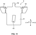
- the support bracket 6 comprises, as shown in FIGS. 10 and 11 , the pair of side wall portions 61 which are provided to interpose the upper column 3 from the both sides, in the vehicle width direction Y, thereof and where the tilting long holes 63 extending in the vertical direction Z are formed, a connection portion 62 (corresponding to a "support-bracket connection portion” in the claims) which interconnects the pair of side wall portions 61, and plural (four, in the present embodiment shown in FIG. 10 ) vehicle-body connection portions 64 which are connected to the vehicle body.
- the connection portion 62 has a bending deformation portion 62a which is operative to be bending-deformed in a direction where respective upper portions of the pair of side wall portions 61 approach each other when the pair of side wall portions 61 receive the fastening force of the bolt 9.
- the bending deformation portion 62a shown in FIG. 10 is a portion which is formed by downward bending a middle part, in the vehicle width direction Y, of the plate-shaped connection portion 62 extending in the vehicle width direction Y so that the connection portion 62 can bend easily. That is, the connection portion 62 with the bending deformation portion 62a shown in FIG. 10 is of a M-letter shape when viewed along the vehicle longitudinal direction X.
- connection portion 62 with the bending deformation portion 62a can be easily deformed in the direction where the respective upper portions of the pair of side wall portions 61 approach each other.
- the pair of pressing plates 7 are respectively arranged on the outward side, in the vehicle width direction Y, of the pair of side wall portions 61 of the support bracket 6.
- the pair of pressing plates 7 press the pair of side wall portions 61 inwardly, in the vehicle width direction Y, thereof when receiving the fastening force of the bolt 9.
- Each of the pair of pressing plates 7 has an insertion hole 7a where the bolt 9 is inserted. Further, the pair of pressing plates 7 have at least a single upper-side convex portion 7b and at least a single lower-side convex portion 7c which protrude toward the side wall portions 61 at respective positions which face the pair of upper-side pressing portions 21 and the pair of lower-side pressing portions 22, interposing the side wall portions 61 therebetween.
- the upper-side convex portions 7b and the lower-side convex portions 7c are arranged on both, forward-and-rearward sides of the insertion holes 7a.
- the bolt 9 penetrates, from the left side, through the insertion holes 7a of the pair of pressing plates 7, the tilting long holes 63 of the pair of side wall portions 61 of the support bracket 6, the bolt insertion holes 26 of the pair of side wall portions 25 of the upper-column biasing portion 12, and also penetrates the protrusion portion 3a of the upper column 3.
- the pair of pressing plates 7, the support bracket 6, the upper-column biasing portion 12, and the upper column 3 can be connected by the single bolt 9.
- the lever 8 comprises a root-side end portion 8b which is connected to the bolt 9 and an operational-side end portion 8a which is positioned on the vehicle rearward side X2 of the bolt 9 and operative to receive an operational force from outside.
- the fastening force can be applied to the bolt 9 which is connected to the root-side end portion 8b and inserted into the tilting long holes 63 or the bolt 9 can be loosened.
- the above-described steering device 1 of the present embodiment comprises the tilt-telescopic mechanism operative 10 to switch the state of the support-side column between the movable state where the upper column 3 is allowed to tilt in the vertical direction Z and move in the axial direction (vehicle longitudinal direction X) and the prohibited state where the upper column's tilting and moving is prohibited.
- the tilt-telescopic mechanism 10 includes the pair of side wall portions 61 provided at the support bracket 6, the bolt 9 penetrating the pair of side wall portions 61 through the tilting long holes 63 and producing the fastening force to press the pair of side wall portions 61 against each other in the approaching direction, the lever 8 operative to change the fasting force by rotationally operating the bolt 9, and the upper-column biasing portion 12 (biasing member) arranged between each of the pair of side wall portions 61 and the upper column 3 and operative to apply the pressing force to the upper column 3 toward its axial center O from the both sides, in the vehicle width direction Y, thereof when the pair of side wall portions 61 receive the fastening force.
- the upper-column biasing portion 12 biasing member
- the fastening force of the bolt 9 can be increased or decreased.
- the function of the tilt-telescopic mechanism 10, that is - switching the state of the upper column 3 between the movable state and the prohibited state can be performed.
- the upper-column biasing portion 12 comprises at least the pair (front-and-rear two pairs in the present embodiment) of upper-side pressing portions 21 pressing the portion of the upper column 3 which is above its axial center O from the both sides, in the vehicle width direction Y, thereof and at least the pair (front-and-rear two pairs in the present embodiment) of lower-side pressing portions 22 pressing the other portion of the upper column 3 which is below its axial center O from the both sides, in the vehicle width direction Y, thereof.
- the upper column 3 comes to be restrained at four separated points, in a peripheral direction, thereof in its axial-direction (vehicle longitudinal direction X) view. Consequently, the upper column 3 can be fixed at the high fastening rigidity between the pair of the side wall portions 61.
- the bolt operational portion is the lever 8 operative to change the fastening force of the bolt 9 inserted into the tilting long holes 63.
- the lever 8 comprises the root-side end portion 8b connected to the bolt 9 and the operational-side end portion 8a positioned on the vehicle rearward side X2 of the bolt 9 and operative to receive the operational force from outside.
- the pair of upper-side pressing portions 21 and the pair of lower-side pressing portions 22 are arranged on the vehicle rearward side X2 of the tilting long holes 63 at least (in the present embodiment, the pair of upper-side pressing portions 21 and the pair of lower-side pressing portions 22 are arranged on the forward-and-rearward both sides of the tilting long holes 63 ).
- the pair of upper-side pressing portions 21 and the pair of lower-side pressing portions 22 of the upper-column biasing portion 12 are arranged on the vehicle rearward side X2 of the position of the bolt 9 inserted into the tilting long holes 63. Therefore, the position of the connection portion where the root-side end portion 8b of the lever 8 is connected to the bolt 9 can be shifted toward the vehicle forward side X1 from the position of the upper-side pressing portion 21 and the lower-side pressing portion 22 which fix the upper column 3. Thereby, the length of the lever 8 can be properly long without changing the position, in the vehicle longitudinal direction X, of the operational-side end portion 8a of the lever 8. Accordingly, the fastening force of the bolt 9 can be properly large without increasing the operational force applied to the operational-side end portion 8a. Consequently, the operability of the lever 8 can improve.
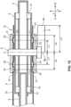
- positional relationships of the lever 8, the bolt 9, and the front-and-rear pressing portions 21 may be considered with a use of a simplified model shown in FIG. 12 .
- a portion where the upper-column biasing portion 12 receives the fastening force of the bolt 9 is the upper-side convex portion 23 which contacts the side wall portion 61 of the support bracket 6.
- L1 the length from the upper-side convex portion 23 to the axial center C of the bolt 9 is defined as L1.
- a portion where the upper-column biasing portion 12 applies the fastening force to the upper column 3 is the upper-side pressing portion 21.
- the length from the upper-side pressing portion 21 to the axial center C of the bolt 9 is defined as L2.
- a portion which receives the operational force from the outside for applying the fastening force to the bolt 9 is the operational-side end portion 8a of the lever 8.
- the length from the operational-side end portion 8a to the axial center C of the bolt 9 is defined as L3.
- the right-side upper-side pressing portion 21 which is positioned on the right side is arranged on the vehicle rearward side X2 (right side) of the position of the bolt 9.
- the length L3 between the operational-side end portion 8a and the axial center C can be set to be longer than the length L1 between the upper-side convex portion 23 and the axial center C or the length L2 between the upper-side pressing portion 21 and the axial center C. Therefore, the connection portion where the root-side end portion 8b of the lever 8 and the bolt 9 are connected can be shifted toward the vehicle forward side X1 from the above-described right-side upper-side pressing portion 21 which fixes the upper column 3. Accordingly, the length of the lever 8 can be made properly long without changing the position, in the vehicle longitudinal direction X, of the operational-side end portion 8a of the lever 8. (3)
- the pair of upper-side pressing portions 21 and the pair of lower-side pressing portions 22 are arranged on the forward-and-rearward both sides, in the vehicle longitudinal direction X, of the tilting long holes 63, respectively.
- the pair of upper-side pressing portions 21 and the pair of lower-side pressing portions 22 of the upper-column biasing portion 12 are respectively arranged at the two separated points, in the longitudinal direction X, thereof in such a manner they enclose the tilting long holes 63 formed at the side wall portions 61 in the view of the vehicle width direction Y.
- the pair of side wall portions 61 can stably fix the upper column 3 by supporting at the front-and-rear two points of the upper-side pressing portion 21 and the front-and-rear two points of the lower-side pressing portion 22 which enclose the tilting long holes 63 in the vehicle-width-direction view (in the view of the vehicle width direction Y), i.e., at a total of four points of the pressing portions. (4)
- the steering device 1 of the present embodiment further comprises, as shown in FIGS. 1-6 , the pair of pressing plates 7 arranged on the respective outward sides, in the vehicle width direction Y, of the pair of side wall portions 61 and operative to press the pair of side wall portions 61 to the respective inward sides, in the vehicle width direction Y, thereof when receiving the fastening force of the bolt 9.
- This pair of pressing plates 7 respectively have the upper-side convex portions 7b and the lower-side convex portions 7c which protrude toward the side wall portions 61 at the respective positions which face the pair of upper-side pressing portions 21 and the pair of lower-side pressing portions 22, interposing the side wall portions 61 therebetween.
- the upper-side convex portions 7b and the lower-side convex portions 7c can press the upper-side pressing portions 21 and the lower-side pressing portions 22 of the upper-column biasing portion 12 via the side wall portions 61.
- the fastening force of the bolt 9 can be effectively transmitted to the upper-side pressing portions 21 and the lower-side pressing portions 22 of the upper-column biasing portion 12.
- the upper column 3 pressed by the pair of upper-side pressing portions 21 and the pair of lower-side pressing portions 22 of the upper-column biasing portion 12 can be stably fixed between the pair of side wall portions 61.
- each of the side wall portions 25 of the upper-column biasing portion 12 are formed the upper-side convex portion 23 and the lower-side convex portion 24 which respectively protrude outwardly, in the vehicle width direction Y, from the above-described outward face at the respective positions corresponding to the upper-side pressing portion 21 and the lower-side pressing portion 22.
- the upper-side convex portions 7b and the lower-side convex portions 7c of the pressing plates 7 respectively press the upper-side convex portions 23 and the lower-side convex portions 24 which protrude outwardly, in the vehicle direction, of the upper-column biasing portion 12 in a pin-point manner, so that the pressing force can be effectively transmitted from the upper-side convex portions 23 and the lower-side convex portions 24 to the upper-side pressing portions 21 and the lower-side pressing portions 22 which are positioned on the inward sides, in the vehicle width direction, of these portions 23, 24. Therefore, the upper-side pressing portions 21 and the lower-side pressing portions 22 of the upper-column biasing portion 12 can properly fix the upper column 3, effectively pressing that, even if the operational force applied of the lever 8 is not so strong. (6)
- the support bracket 6 further comprises the connection portion 62 to interconnect the pair of side wall portions 61.
- This connection portion 62 has the bending deformation portion 62a operative to be bending-deformed in the direction where the pair of side wall portions 61 approach each other when the pair of side wall portions 61 receive the fastening force of the bolt 9.
- connection portion 62 interconnecting the pair of side wall portions 61 has the bending deformation portion 62a
- the pair of side wall portions 61 can be made close to each other due to bending deformation of the bending-deformation portion 62a when receiving the fastening force of the bolt 9.
- the fastening force of the bolt 9 can be uniformly transmitted to the pair of upper-side pressing portions 21 and the pair of lower-side pressing portions 22 of the upper-column biasing portion 12 arranged between the side wall potions 61 and the upper column 3. Consequently, the upper column 3 pressed by the pair of upper-side pressing portions 21 and the pair of lower-side pressing portions 22 of the upper-column biasing portion 12 can be stably fixed between the pair of side wall portions 61.
- the upper-column biasing portion 12 further has the pair of support portions 15 extending in the vehicle longitudinal direction X and supporting the pair of upper-side pressing portions 21 and the pair of lower-side pressing portions 22, respectively, and the connection portion 16 to interconnect the respective end portions at the vehicle forward side X1 of the pair of support portions 15.
- the pair of support portions 15 are configured to be bending-deformed toward the inward side, in the vehicle width direction Y, thereof when the pair of upper-side pressing portions 21 and the pair of lower-side pressing portions 22 receive the fastening force of the bolt 9 (for example, the support portion 15 is made of a M-letter shaped plate member deformable in the vehicle width direction Y).
- the pair of support portions 15 supporting the upper-side pressing portions 21 and the lower-side pressing portions 22, respectively come to be bending-deformed toward the inward side, in the vehicle width direction Y, thereof when these portions 21, 22 receive the fastening force of the bolt 9, the upper column 3 pressed by the pair of upper-side pressing portions 21 and the pair of lower-side pressing portions 22 of the upper-column biasing portion 12 can be stably fixed between the pair of side wall portions 61.
- the present invention is not limited to this.
- the lower column portion 11 and the upper-column biasing portion 12 may be made as separated independent parts. That is, the lower column portion 11 may be a cylindrical-shaped unit member, and the upper-column biasing portion 12 may be another unit member which comprises at least the pair of upper-side pressing portions 21 and the lower-side pressing portions 22.
- the steering device 1 of the above-described embodiment has the supporting structure of the upper column 3, in which the support bracket 6 supports the upper column 3 and the upper-column biasing portion 12 comprises at least the pair of upper-side pressing portions 21 pressing the portion of the upper column 3 which is above the axial center O of the upper column 3 from the both sides, in the vehicle width direction Y, thereof and the pair of lower-side pressing portions 22 pressing the other portion of the upper column 3 which is below the axial center O from the both sides, in the vehicle width direction Y, thereof.
- the present invention is not limited to this supporting structure.
- the present invention can be achieved as long as the support bracket supports the support-side column which is either one of the lower column and the upper column and the biasing member comprises at least a pair of upper-side pressing portions provided to press a portion of the support-side column which is above the axial center of the support-side column from the both sides, in the vehicle width direction, thereof and at least a pair of lower-side pressing portions provided to press another portion of the support-side column which is below the axial center of the support-side column from the both sides, in the vehicle width direction, thereof.
- the support bracket supports the lower column and at least the pair of upper-side pressing portions and at least the pair of lower-side pressing portions press the upper-side portions and the lower-side portions of the lower column toward its axial center can be included in the scope of the present invention as well.
- the lever 8 is exemplified as the bolt operational portion operative to change the fastening force of the bolt 9 through its rotational operation in the above-described embodiment
- the present invention is not limited to this. Any portion can be included in the bolt operational portion of the present invention as long as it is capable of changing the fastening force of the bolt by rotating the bolt 9.
- an electromotive actuator to rotatably operate a bolt is applicable as well.
Landscapes
- Engineering & Computer Science (AREA)
- Chemical & Material Sciences (AREA)
- Combustion & Propulsion (AREA)
- Transportation (AREA)
- Mechanical Engineering (AREA)
- Steering Controls (AREA)
Abstract
Description
- The present invention relates to a steering device in which a steering shaft is expandable and tiltable.
- Conventionally, various types of steering device for a vehicle in which the expandable and tiltable steering shaft can be fixed at a desired length and angle has been proposed.
- The steering device disclosed in
JP S59-128054 A - The reinforcement bracket is a roughly U-shaped plate member to cover a lower half of the upper and lower jackets and has a pair of pressing portions facing to each other.
- In a state where the bolt is fastened, the fastening force of the bolt makes a distance between the pair of pressing portions of the reinforcement narrower, thereby pressing the lower half of the upper and lower jackets engaged with each other toward an inward side from an outward side, in the vehicle width direction, thereof, so that the upper and lower jackets can be fixed at the desired length and angle.
- In the above-described steering device, while the pair of pressing portions with the narrowed distance caused by the fastening force of the bolt press the lower half of the upper and lower jackets engaged with each other (support column) toward the inward side from the outward side, in the vehicle width direction, thereof, an upper half of the upper and lower jackets does not receive any pressing force. Accordingly, it is difficult to increase the fastening rigidity in the event of fastening the upper and lower jackets.
- Further, since the above-described structure requires that a strong pressing force is applied only to the lower half of the upper and lower jackets and thereby a whole part of the upper and lower jackets is fixed, it may be unavoidable to increase the fastening force of the bolt. Therefore, there is a concern that improperly long time may be required to release the bolt's fastening completely in the event of releasing the bolt's fastening and also in a case where the fastening force of the bolt is not released sufficiently, the tilting and axial moving of the upper and lower jackets may not be conducted smoothly.
- The present invention has been devised in view of the above-described matter, and an object of the present invention is to provide a steering device which can properly fix a steering column supporting a steering shaft at the high fastening rigidity and conduct the tilting and axial moving of a steering column smoothly in the event of releasing the bolt's fastening.
- The steering device of the present invention comprises an upper shaft extending in a vehicle longitudinal direction and having a rear end portion to which a steering wheel is fixed, an upper column rotatably supporting the upper shaft, a lower shaft connected to a front end portion of the upper shaft so as to slide in an axial direction, a lower column rotatably supporting the lower shaft and provided to be movable in an axial direction relative to the upper column, a support bracket fixed to a vehicle body and supporting a support-side column which is either one of the lower column and the upper column, and a tilt-telescopic mechanism operative to switch a state of the support-side column between a movable state where the support-side column is allowed to tilt in a vertical direction and move in an axial direction and a prohibited state where the support-side column's tilting and moving is prohibited, wherein the tilt-telescopic mechanism includes a pair of side wall portions provided at the support bracket to interpose the support-side column therebetween from both sides in a vehicle width direction and having tilting long holes extending in the vertical direction, a bolt penetrating the pair of side wall portions through the tilting long holes and producing a fastening force to press the pair of side wall portions against each other in an approaching direction, a bolt operational portion operative to change the fasting force by rotationally operating the bolt, and a biasing member arranged between each of the pair of side wall portions and the support-side column and operative to apply a pressing force to the support-side column from the both sides, in the vehicle width direction, thereof when the pair of side wall portions receive the fastening force, and the biasing member comprises at least a pair of upper-side pressing portions provided to press a portion of the support-side column which is above an axial center of the support-side column from the both sides, in the vehicle width direction, thereof and at least a pair of lower-side pressing portions provided to press another portion of the support-side column which is below the axial center of the support-side column from the both sides, in the vehicle width direction, thereof.
- In the above-described steering device, either one of the upper column and the lower column is supported at the support bracket as the support-side column, and the state of the support-side column is switched, by the tilt-telescopic mechanism, between the movable state where the support-side column is allowed to tilt in the vertical direction and move in the axial direction and the prohibited state where the support-side column's tilting and moving is prohibited. The tilt-telescopic mechanism comprises the biasing member which is arranged between each of the pair of side wall portions of the support bracket and the support-side column so as to apply the pressing force to the support-side column from the both sides, in the vehicle width direction, thereof when the pair of side wall portions receive the fastening force.
- The above-described biasing member comprises at least the pair of upper-side pressing portions pressing the portion of the support-side column which is above its axial center from the both sides, in the vehicle width direction, thereof and at least the pair of lower-side pressing portions pressing another portion of the support-side column which is below its axial center from the both sides, in the vehicle width direction, thereof.
- Accordingly, when the pair of side wall portions of the tilt-telescopic mechanism receive the fastening force of the bolt, since upper-and-lower both sides of the axial center of the support-side column are pressed from the both sides, in the vehicle width direction, thereof by the pair of upper-side pressing portions and the pair of lower-side pressing portion of the biasing member, the support-side column comes to be restrained at four separated points, in a peripheral direction, thereof in its axial-direction view. Consequently, the support-side column can be fixed at the properly-high fastening rigidity between the pair of the side wall portions.
- Meanwhile, in the releasing state where the pair of side wall portions do not receive the fastening force, the upper-and-lower both sides of the axial center of the support-side column do not receive any pressing force from the biasing member. Consequently, the vertical tilting and axial moving of the support-side column can be conducted smoothly.
- In the above-described steering device, it is preferable that the bolt operational portion be a lever operative to change the fastening force of the bolt inserted into the tilting long holes, this lever comprise a root-side end portion connected to the bolt and an operational-side end portion positioned on a vehicle rearward side of the bolt and operative to receive an operational force from outside, and the pair of upper-side pressing portions and the pair of lower-side pressing portions be arranged on the vehicle rearward side of the tilting long holes.
- According to this structure, since the pair of upper-side pressing portions and the pair of lower-side pressing portions of the biasing member are arranged on the vehicle rearward side of a position of the bolt inserted into the tilting long holes, a position of a connection portion where the root-side end portion of the lever (the bolt operational portion) is connected to the bolt can be shifted toward a vehicle forward side from a position of the upper-side pressing portion and the lower-side pressing portion which fix the support-side column. Thereby, the length of the lever can be properly long without changing a longitudinal position of the operational-side end portion of the lever. Accordingly, the fastening force of the bolt can be properly large without increasing the operational force applied to the operational-side end portion. Consequently, the operability of the lever can improve.
- In the above-described steering device, it is preferable that the pair of upper-side pressing portions and the pair of lower-side pressing portions be arranged on forward-and-rearward both sides, in the vehicle longitudinal direction, of the tilting long holes, respectively.
- According to this structure, the pair of upper-side pressing portions and the pair of lower-side pressing portions of the biasing member are respectively arranged at two separated points, in the longitudinal direction, thereof in such a manner they enclose the tilting long holes formed at the side wall portions in a vehicle-width-direction view. Therefore, the pair of side wall portions can stably fix the support-side column by supporting at the front-and-rear two points of the upper-side pressing portion and the front-and-rear two points of the lower-side pressing portion which enclose the tilting long holes in the vehicle-width-direction view, i.e., at a total of four points of the pressing portions.
- In the above-described steering device, it is preferable that the steering device further comprise a pair of pressing plates arranged on respective outward sides, in the vehicle width direction, of the pair of side wall portions and operative to press the pair of side wall portions to respective inward sides, in the vehicle width direction, thereof when receiving the fastening force of the bolt, and the pair of pressing plates have respective convex portions which protrude toward the side wall portions at respective positions which face the pair of upper-side pressing portions and the pair of lower-side pressing portions, interposing the side wall portions therebetween.
- According to this structure, when the pressing plates receive the fastening force of the bolt, the convex portions can press the upper-side pressing portions and the lower-side pressing portions of the biasing member via the side wall portions. Thereby, the fastening force of the bolt can be effectively transmitted to the upper-side pressing portions and the lower-side pressing portions of the biasing member. As a result, the support-side column pressed by the pair of upper-side pressing portions and the pair of lower-side pressing portions of the biasing member can be stably fixed between the pair of side wall portions.
- In the above-described steering device, it is preferable that the support bracket further comprise a support-bracket connection portion to interconnect the pair of side wall portions, and the support-bracket connection portion have a bending deformation portion operative to be bending-deformed in a direction where the pair of side wall portions approach each other when the pair of side wall portions receive the fastening force of the bolt.
- According to this structure, since the support-bracket connection portion interconnecting the pair of side wall portions has the bending deformation portion, the pair of side wall portions can be made close to each other due to bending deformation of the bending-deformation portion when receiving the fastening force of the bolt. Thereby, the fastening force of the bolt can be uniformly transmitted to the pair of upper-side pressing portions and the pair of lower-side pressing portions of the biasing member arranged between the side wall potions and the support-side column. Consequently, the support-side column pressed by the pair of upper-side pressing portions and the pair of lower-side pressing portions of the biasing member can be stably fixed between the pair of side wall portions.
- In the above-described steering device, it is preferable that the biasing member further have a pair of support portions extending in the vehicle longitudinal direction and supporting the pair of upper-side pressing portions and the pair of lower-side pressing portions, respectively, and a biasing-member connection portion to interconnect vehicle-forward-side end portions of the pair of support portions, and the pair of support portions be configured to be bending-deformed toward an inward side, in the vehicle width direction, thereof when the pair of upper-side pressing portions and the pair of lower-side pressing portions receive the fastening force of the bolt.
- According to this structure, since the pair of support portions supporting the upper-side pressing portions and the lower-side pressing portions, respectively, come to be are bending-deformed toward the inward side, in the vehicle width direction, thereof when the upper-side pressing portions and the lower-side pressing portions receive the fastening force of the bolt, the support-side column pressed by the pair of upper-side pressing portions and the pair of lower-side pressing portions of the biasing member can be stably fixed between the pair of side wall portions.
- As described above, the steering device of the present invention can properly fix the column to support the shaft at the high fastening rigidity and conduct the tilting and axial moving of the column smoothly in the event of releasing the bolt's fastening.
- The present invention will become apparent from the following description which refers to the accompanying drawings.
-
-
FIG. 1 is a perspective view showing an entire structure of a steering device according to an embodiment of the present invention. -
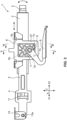
FIG. 2 is a plan view of the steering device shown inFIG. 1 . -
FIG. 3 is an elevational view of the steering device shown inFIG. 1 . -
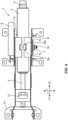
FIG. 4 is a bottom view of the steering device shown inFIG. 1 . -
FIG. 5 is a sectional view taken along line V-V ofFIG. 3 . -
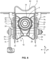
FIG. 6 is a sectional view taken along line VI-VI ofFIG. 3 . -
FIG. 7 is a perspective view of an outer column shown inFIG. 1 . -
FIG. 8 is a bottom view of the outer column shown inFIG. 1 . -
FIG. 9 is a view of the outer column shown inFIG. 7 , when viewed from a vehicle rearward side. -
FIG. 10 is a perspective view of a support bracket shown inFIG. 1 . -
FIG. 11 is an elevational view of the support bracket shown inFIG. 10 . -
FIG. 12 is an explanatory diagram showing a positional-relationship state where upper pressing portions of an upper-column biasing portion are arranged on forward-and-rearward both sides of a bolt and an operational-side end portion of a lever is arranged on a vehicle rearward side of the upper pressing portions. - Hereafter, a steering device according to an embodiment of the present invention will be described specifically referring to the drawings.
- A steering device 1 of the present embodiment shown in
FIGS. 1 - 6 is arranged along a vehicle longitudinal direction X in such a manner that it protrudes toward a cabin inside from an engine room provided in a vehicle body of an automotive vehicle, which is used as the steering device of a vehicle. - This steering device 1 is configured such that a steering shaft composed of an
upper shaft 2 and alower shaft 4 is configured to be expandable and tiltable and also be fixable at the desired length and angle. - Specifically, the steering device 1 comprises the
upper shaft 2, anupper column 3 which rotatably supports theupper shaft 2, thelower shaft 4 which is connected to a front end portion (an end portion at a vehicle forward side X1) of theupper shaft 2 so as to slide in an axial direction, a lower column portion 11 (lower column) which rotatably supports thelower shaft 4 and includes an upper-column biasing portion 12 (biasing member), asupport bracket 6 which supports theupper column 3, a pair ofpressing plates 7 which are arranged on both sides, in a vehicle width direction Y, of thesupport bracket 6, abolt 9 and anut 14 which are together operative to fasten thesupport bracket 6 and the pair ofpressing plates 7 from respective outward sides, in the vehicle width direction Y, thereof, alever 8 as a bolt operational portion which is connected to a head-side portion of thebolt 9 and operative to change a fastening force of thebolt 9 by rotating thebolt 9, and an outer-column support bracket 13 which supports so that theouter column 5 can tilt in a vertical direction Z. Herein, since thenut 14 is fixed at an outer face of thepressing plate 7 without rotation, thebolt 9 can be fastened or released by a driver's operation of thelever 8. Further, thelever 8 is specifically configured such that acam 18 attached to thebolt 9 is rotatably operated so as to ride up and down, thereby changing a state where the fastening force ofbolt 9 is generated or not. - The
support bracket 6 and the outer-column support bracket 13 are fixed at the vehicle body by bolts or the like. By weakening the fastening force of thebolt 9 by an operation of thelever 8, theupper shaft 2, theupper column 3, thelower shaft 4, theouter column 5, and the pair ofpressing plates 7 are made tiltable in the vertical direction Z around asupport axis 13a of the outer-column support bracket 13 (see a tilt direction T shown inFIG. 1 ). At the same time, theupper shaft 2 and theupper column 3 are made slidable in the vehicle longitudinal direction X relative to thelower shaft 4 and the outer column 5 (see a slide direction S shown inFIG. 1 ). After theupper shaft 2 is moved to the angle and longitudinal position, in the longitudinal direction X, desired by an operator, the fastening operation of thebolt 9 can easily make the steering device 1 return to its fixing state. - Hereafter, each component of the steering device 1 will be described.
- The
upper shaft 2 is a bar-shaped member extending in the vehicle longitudinal direction X, and a steering wheel (not illustrated) is fixed to its rear end portion (an end portion at a vehicle rearward side X2). - The
upper column 3 is a cylindrical member rotatably supporting theupper shaft 2. Theupper column 3 includes plural bearings 31 (seeFIGS. 1 ,5 - 6 , and12 ) which support front-and-rear end portions of theupper shaft 2. - In the present embodiment, as shown in
FIGS. 4 and5 , arectangular protrusion portion 3a which protrudes downward is formed in a certain area of a lower-side portion of theupper column 3 which overlaps, in the vehicle longitudinal direction X, the upper-column biasing portion 12. Thebolt 9 penetrates thisrectangular protrusion portion 3a in the vehicle width direction Y. Further, therectangular protrusion portion 3a is exposed to a downward side through arectangular opening 12a of the upper-column biasing portion 12. Herein, since therectangular opening 12a has a wider width, in the longitudinal direction, X than therectangular protrusion portion 3a, the upper-column biasing portion 12 does not prevent a move, in the longitudinal direction X, of theupper column 3. - The
lower shaft 4 is a bar-shaped member which is connected to the front end portion (the end portion at the vehicle forward side X1) of theupper shaft 2 so as to slide in the axial direction. More specifically, thelower shaft 4 has a telescopic structure (seeFIG. 12 ) in which thelower shaft 4 is slidable in the axial direction relative to theupper shaft 2, and thelower shaft 4 is coupled to the upper shaft 2 (e.g., via a spline coupling) in such a manner that it can rotate together with theupper shaft 2. - As shown in
FIGS. 7-9 , theouter column 5 is a member which includes the lower column portion 11 (lower column) which rotatably supports thelower shaft 4 and the upper-column biasing portion 12 (biasing member). In other words, theouter column 5 of the present embodiment is constituted by the lower column portion 11 (lower column) and the upper-column biasing portion 12 (biasing member) which are integrated. - The
lower column portion 11 is a portion which is movable in the axial direction (vehicle longitudinal direction X) relative to theupper column 3 as well as rotatably supports thelower shaft 4. In the present embodiment, a whole part of theouter column 5 including thelower column portion 11 is movable in the axial direction (vehicle longitudinal direction X) relative to theupper column 3 as well. - The
lower column portion 11 has a bearing 32 (seeFIG. 1 ) which rotatably supports an end portion at the vehicle forward side X1 of thelower shaft 4 inside its cylindrical body. - The upper-
column biasing portion 12 is the biasing member which is arranged between a pair of side wall portions 61 (described later) (seeFIGS. 3 ,5 ,6 ,10 and11 ) of thesupport bracket 6 and theupper column 3 and also operative to apply a pressing force to theupper column 3 toward its axial center O from the both sides, in the vehicle width direction Y, thereof when the pair ofside wall portions 61 receive the fastening force of thebolt 9. - As shown in
FIGS. 6-9 , the upper-column biasing portion 12 comprises at least a pair (front-and-rear two pairs in the present embodiment) of upper-sidepressing portions 21 which are provided to press a portion of theupper column 3 which is above the axial center O of theupper column 3 toward the axial center O from the both sides, in the vehicle width direction Y, thereof, at least a pair (front-and-rear two pairs in the present embodiment) of lower-sidepressing portions 22 which is provided to press another portion of theupper column 3 which is below the axial center O toward the axial center O from the both sides, in the vehicle width direction Y, thereof, and a pair ofside wall portions 25 which support the pair of upper-sidepressing portions 21 and the pair of lower-sidepressing portions 22 on the both sides, respectively. - Each of the
side wall portions 25 has abolt insertion hole 26 for insertion of thebolt 9 at a position overlapping a tilting long hole 63 (described later) (seeFIGS. 7 ,10 and11 ) which is formed at theside wall portion 61 of thesupport backet 6. - In the present embodiment, the pair of upper-side
pressing portions 21 and the pair of lower-sidepressing portions 22 are positioned at least on the vehicle rearward side X2 of the tilting long holes 63. - More specifically, the pair of upper-side
pressing portions 21 and the pair of lower-sidepressing portions 22 of the present embodiment are arranged on the forward-and-rearward both sides, in the vehicle longitudinal direction X, of the tiltinglong holes 63, respectively. - The upper-side
pressing portion 21 and the lower-sidepressing portion 22 are arranged on the inward side, in the vehicle width direction Y, of the side wall portion 25 (on a facing side of the pair of side wall portions 25). In the present embodiment, the upper-sidepressing portion 21 and the lower-sidepressing portion 22 are integrally formed with theside wall portion 25, which are specifically formed by a plate-shaped portion which is configured to bend inwardly, in the vehicle width direction Y, from upper-and-lower both end portions of theside wall portion 25. - At an outward face, in the vehicle width direction Y, of each of the
side wall portions 25 are formed an upper-sideconvex portion 23 and a lower-sideconvex portion 24 which respectively protrude outwardly, in the vehicle width direction Y, from the above-described outward face at respective positions corresponding to the upper-sidepressing portion 21 and the lower-sidepressing portion 22. - In the present embodiment, the upper-
column biasing portion 12 further comprises a pair ofsupport portions 15 which extend toward the vehicle forward side X1, in the vehicle longitudinal direction X, from respective front end portions of the pair side wall portions 25 (from respective end portions at the vehicle forward side X1) and a connection portion 16 (corresponding to a "biasing-member connection portion" in the claims) to interconnect respective end portions at the vehicle forward side X1 of the pair ofsupport portions 15. - The pair of
support portions 15 respectively support the upper-sidepressing portions 21 and the lower-sidepressing portions 22 via the pair ofside wall portions 25. The pair ofsupport portions 15 are configured to be bending-deformed toward the inward side, in the vehicle width direction Y, thereof when the pair of upper-sidepressing portions 21 and the pair of lower-sidepressing portions 22 receive the fastening force of thebolt 9. Specifically, as shown inFIG. 7 , thesupport portion 15 is a plate-shaped portion which is bendable in the vehicle width direction Y, and its end portion at the vehicle forward side X1 is fixed to theconnection portion 16, thereby forming a cantilever-beam state. An end portion at the vehicle rearward side X2 of thesupport portion 15 is connected to the upper-sidepressing portion 21 and the lower-sidepressing portion 22. When the fastening force of thebolt 9 inserted into the bolt insertion holes 26 is applied to the pair ofside wall portions 25, this force is transmitted to the upper-sidepressing portions 21 and the lower-sidepressing portions 22, so that the pair of plate-shapedsupport portions 15 are bending-deformed inwardly, in the vehicle width direction, thereof. - The
connection portion 16 of the present embodiment further comprises a pair ofside wall portions 16a which are arranged on the both sides, in the vehicle width direction Y, of thelower column portion 11 and connected to the respective end portions at the vehicle forward side X1 of the pair ofsupport portions 15 and a bottom-wall portion 16b which extends in the vehicle width direction Y below thelower column portion 11 and interconnects respective lower ends of the pair ofside wall portions 16a. Theconnection portion 16 further comprises a pair ofcolumn connection portions 16c which respectively interconnect the pair ofside wall portions 16a and thelower column portion 11. - The
outer column 5 of the present embodiment includes a pair of plate-shapedarm portions 17 which extend toward the vehicle forward side X1 further from the respective front end portions of the pair ofside wall portions 16a of theconnection portion 16. Anaxial hole 17a is formed at each end portion at the vehicle forward side X1 of the pair ofarm portions 17. Asupport axis 13a of the outer-column support bracket 13 shown inFIGS. 1 and3 is rotatably supported at theaxial hole 17a. Thereby, theouter column 5 is supported at the outer-column support bracket 13 so as to tilt in the vertical direction Z around thesupport axis 13a (see the tilt direction T inFIG. 1 ). - The
support bracket 6 is a member which is fixed to the vehicle body and supports a support-side column which is either one of thelower column portion 11 and theupper column 3, specifically theupper column 3 in the present embodiment. - Specifically, the
support bracket 6 comprises, as shown inFIGS. 10 and11 , the pair ofside wall portions 61 which are provided to interpose theupper column 3 from the both sides, in the vehicle width direction Y, thereof and where the tiltinglong holes 63 extending in the vertical direction Z are formed, a connection portion 62 (corresponding to a "support-bracket connection portion" in the claims) which interconnects the pair ofside wall portions 61, and plural (four, in the present embodiment shown inFIG. 10 ) vehicle-body connection portions 64 which are connected to the vehicle body. - The
connection portion 62 has abending deformation portion 62a which is operative to be bending-deformed in a direction where respective upper portions of the pair ofside wall portions 61 approach each other when the pair ofside wall portions 61 receive the fastening force of thebolt 9. The bendingdeformation portion 62a shown inFIG. 10 is a portion which is formed by downward bending a middle part, in the vehicle width direction Y, of the plate-shapedconnection portion 62 extending in the vehicle width direction Y so that theconnection portion 62 can bend easily. That is, theconnection portion 62 with the bendingdeformation portion 62a shown inFIG. 10 is of a M-letter shape when viewed along the vehicle longitudinal direction X. Thus, since the bendingdeformation portion 62a is deformed when the pair ofside wall portions 61 receive the fastening force of thebolt 9, theconnection portion 62 with the bendingdeformation portion 62a can be easily deformed in the direction where the respective upper portions of the pair ofside wall portions 61 approach each other. - As shown in
FIGS. 1-6 , the pair ofpressing plates 7 are respectively arranged on the outward side, in the vehicle width direction Y, of the pair ofside wall portions 61 of thesupport bracket 6. The pair ofpressing plates 7 press the pair ofside wall portions 61 inwardly, in the vehicle width direction Y, thereof when receiving the fastening force of thebolt 9. - Each of the pair of
pressing plates 7 has aninsertion hole 7a where thebolt 9 is inserted. Further, the pair ofpressing plates 7 have at least a single upper-sideconvex portion 7b and at least a single lower-sideconvex portion 7c which protrude toward theside wall portions 61 at respective positions which face the pair of upper-sidepressing portions 21 and the pair of lower-sidepressing portions 22, interposing theside wall portions 61 therebetween. In the present embodiment, as shown inFIG. 3 , the upper-sideconvex portions 7b and the lower-sideconvex portions 7c are arranged on both, forward-and-rearward sides of theinsertion holes 7a. - As shown in
FIG. 5 , thebolt 9 penetrates, from the left side, through theinsertion holes 7a of the pair ofpressing plates 7, the tiltinglong holes 63 of the pair ofside wall portions 61 of thesupport bracket 6, the bolt insertion holes 26 of the pair ofside wall portions 25 of the upper-column biasing portion 12, and also penetrates theprotrusion portion 3a of theupper column 3. Thus, the pair ofpressing plates 7, thesupport bracket 6, the upper-column biasing portion 12, and theupper column 3 can be connected by thesingle bolt 9. - As shown in
FIG. 1 , thelever 8 comprises a root-side end portion 8b which is connected to thebolt 9 and an operational-side end portion 8a which is positioned on the vehicle rearward side X2 of thebolt 9 and operative to receive an operational force from outside. By applying the operational force to the operational-side end portion 8a of thelever 8 in the vertical direction Z, the fastening force can be applied to thebolt 9 which is connected to the root-side end portion 8b and inserted into the tiltinglong holes 63 or thebolt 9 can be loosened. - (1) The above-described steering device 1 of the present embodiment comprises the tilt-
telescopic mechanism operative 10 to switch the state of the support-side column between the movable state where theupper column 3 is allowed to tilt in the vertical direction Z and move in the axial direction (vehicle longitudinal direction X) and the prohibited state where the upper column's tilting and moving is prohibited. Specifically, the tilt-telescopic mechanism 10 includes the pair ofside wall portions 61 provided at thesupport bracket 6, thebolt 9 penetrating the pair ofside wall portions 61 through the tiltinglong holes 63 and producing the fastening force to press the pair ofside wall portions 61 against each other in the approaching direction, thelever 8 operative to change the fasting force by rotationally operating thebolt 9, and the upper-column biasing portion 12 (biasing member) arranged between each of the pair ofside wall portions 61 and theupper column 3 and operative to apply the pressing force to theupper column 3 toward its axial center O from the both sides, in the vehicle width direction Y, thereof when the pair ofside wall portions 61 receive the fastening force. - By applying the operational force to the operational-
side end portion 8a of thelever 8 in the vertical direction Z, the fastening force of thebolt 9 can be increased or decreased. Thus, the function of the tilt-telescopic mechanism 10, that is - switching the state of theupper column 3 between the movable state and the prohibited state can be performed. - As shown in
FIGS. 6 and7 , the upper-column biasing portion 12 comprises at least the pair (front-and-rear two pairs in the present embodiment) of upper-sidepressing portions 21 pressing the portion of theupper column 3 which is above its axial center O from the both sides, in the vehicle width direction Y, thereof and at least the pair (front-and-rear two pairs in the present embodiment) of lower-sidepressing portions 22 pressing the other portion of theupper column 3 which is below its axial center O from the both sides, in the vehicle width direction Y, thereof. - Accordingly, when the pair of
side wall portions 61 receive the fastening force of thebolt 9, since the upper-and-lower both sides of the axial center O of theupper column 3 are pressed from the both sides, in the vehicle width direction Y, thereof by the pair of upper-sidepressing portions 21 and the pair of lower-sidepressing portion 22 of the upper-column biasing portion 12, theupper column 3 comes to be restrained at four separated points, in a peripheral direction, thereof in its axial-direction (vehicle longitudinal direction X) view. Consequently, theupper column 3 can be fixed at the high fastening rigidity between the pair of theside wall portions 61. - Meanwhile, in the releasing state where the pair of
side wall portions 61 do not receive the fastening force, the upper-and-lower both sides of the axial center O of theupper column 3 do not receive any pressing force from the upper-column biasing portion 12. Consequently, the vertical tilting and axial moving of theupper column 3 can be conducted smoothly.
(2) - In the steering device 1 of the present embodiment, the bolt operational portion is the
lever 8 operative to change the fastening force of thebolt 9 inserted into the tilting long holes 63. As shown inFIG. 1 , thelever 8 comprises the root-side end portion 8b connected to thebolt 9 and the operational-side end portion 8a positioned on the vehicle rearward side X2 of thebolt 9 and operative to receive the operational force from outside. The pair of upper-sidepressing portions 21 and the pair of lower-sidepressing portions 22 are arranged on the vehicle rearward side X2 of the tiltinglong holes 63 at least (in the present embodiment, the pair of upper-sidepressing portions 21 and the pair of lower-sidepressing portions 22 are arranged on the forward-and-rearward both sides of the tilting long holes 63). - According to this structure, the pair of upper-side
pressing portions 21 and the pair of lower-sidepressing portions 22 of the upper-column biasing portion 12 are arranged on the vehicle rearward side X2 of the position of thebolt 9 inserted into the tilting long holes 63. Therefore, the position of the connection portion where the root-side end portion 8b of thelever 8 is connected to thebolt 9 can be shifted toward the vehicle forward side X1 from the position of the upper-sidepressing portion 21 and the lower-sidepressing portion 22 which fix theupper column 3. Thereby, the length of thelever 8 can be properly long without changing the position, in the vehicle longitudinal direction X, of the operational-side end portion 8a of thelever 8. Accordingly, the fastening force of thebolt 9 can be properly large without increasing the operational force applied to the operational-side end portion 8a. Consequently, the operability of thelever 8 can improve. - For example, positional relationships of the
lever 8, thebolt 9, and the front-and-rearpressing portions 21 may be considered with a use of a simplified model shown inFIG. 12 . A portion where the upper-column biasing portion 12 receives the fastening force of thebolt 9 is the upper-sideconvex portion 23 which contacts theside wall portion 61 of thesupport bracket 6. Herein, in a case where an axial center C of thebolt 9 is considered as a standard position, the length from the upper-sideconvex portion 23 to the axial center C of thebolt 9 is defined as L1. Next, a portion where the upper-column biasing portion 12 applies the fastening force to theupper column 3 is the upper-sidepressing portion 21. Herein, the length from the upper-sidepressing portion 21 to the axial center C of thebolt 9 is defined as L2. Meanwhile, a portion which receives the operational force from the outside for applying the fastening force to thebolt 9 is the operational-side end portion 8a of thelever 8. The length from the operational-side end portion 8a to the axial center C of thebolt 9 is defined as L3. - As shown in
FIG. 12 , the right-side upper-sidepressing portion 21 which is positioned on the right side is arranged on the vehicle rearward side X2 (right side) of the position of thebolt 9. According to the positional relationships shown inFIG. 12 , the length L3 between the operational-side end portion 8a and the axial center C can be set to be longer than the length L1 between the upper-sideconvex portion 23 and the axial center C or the length L2 between the upper-sidepressing portion 21 and the axial center C. Therefore, the connection portion where the root-side end portion 8b of thelever 8 and thebolt 9 are connected can be shifted toward the vehicle forward side X1 from the above-described right-side upper-sidepressing portion 21 which fixes theupper column 3. Accordingly, the length of thelever 8 can be made properly long without changing the position, in the vehicle longitudinal direction X, of the operational-side end portion 8a of thelever 8.
(3) - In the steering device 1 of the present embodiment, as shown in
FIG. 7 , the pair of upper-sidepressing portions 21 and the pair of lower-sidepressing portions 22 are arranged on the forward-and-rearward both sides, in the vehicle longitudinal direction X, of the tiltinglong holes 63, respectively. - According to this structure, the pair of upper-side
pressing portions 21 and the pair of lower-sidepressing portions 22 of the upper-column biasing portion 12 are respectively arranged at the two separated points, in the longitudinal direction X, thereof in such a manner they enclose the tiltinglong holes 63 formed at theside wall portions 61 in the view of the vehicle width direction Y. Therefore, the pair ofside wall portions 61 can stably fix theupper column 3 by supporting at the front-and-rear two points of the upper-sidepressing portion 21 and the front-and-rear two points of the lower-sidepressing portion 22 which enclose the tiltinglong holes 63 in the vehicle-width-direction view (in the view of the vehicle width direction Y), i.e., at a total of four points of the pressing portions.
(4) - The steering device 1 of the present embodiment further comprises, as shown in
FIGS. 1-6 , the pair ofpressing plates 7 arranged on the respective outward sides, in the vehicle width direction Y, of the pair ofside wall portions 61 and operative to press the pair ofside wall portions 61 to the respective inward sides, in the vehicle width direction Y, thereof when receiving the fastening force of thebolt 9. This pair ofpressing plates 7 respectively have the upper-sideconvex portions 7b and the lower-sideconvex portions 7c which protrude toward theside wall portions 61 at the respective positions which face the pair of upper-sidepressing portions 21 and the pair of lower-sidepressing portions 22, interposing theside wall portions 61 therebetween. - According to this structure, when the
pressing plates 7 receive the fastening force of thebolt 9, the upper-sideconvex portions 7b and the lower-sideconvex portions 7c can press the upper-sidepressing portions 21 and the lower-sidepressing portions 22 of the upper-column biasing portion 12 via theside wall portions 61. Thereby, the fastening force of thebolt 9 can be effectively transmitted to the upper-sidepressing portions 21 and the lower-sidepressing portions 22 of the upper-column biasing portion 12. As a result, theupper column 3 pressed by the pair of upper-sidepressing portions 21 and the pair of lower-sidepressing portions 22 of the upper-column biasing portion 12 can be stably fixed between the pair ofside wall portions 61.
(5) - Further, in the present embodiment, at the outward (back side) face, in the vehicle width direction Y, of each of the
side wall portions 25 of the upper-column biasing portion 12 are formed the upper-sideconvex portion 23 and the lower-sideconvex portion 24 which respectively protrude outwardly, in the vehicle width direction Y, from the above-described outward face at the respective positions corresponding to the upper-sidepressing portion 21 and the lower-sidepressing portion 22. Accordingly, when thepressing plates 7 receive the fastening force of thebolt 9, the upper-sideconvex portions 7b and the lower-sideconvex portions 7c of thepressing plates 7 respectively press the upper-sideconvex portions 23 and the lower-sideconvex portions 24 which protrude outwardly, in the vehicle direction, of the upper-column biasing portion 12 in a pin-point manner, so that the pressing force can be effectively transmitted from the upper-sideconvex portions 23 and the lower-sideconvex portions 24 to the upper-sidepressing portions 21 and the lower-sidepressing portions 22 which are positioned on the inward sides, in the vehicle width direction, of theseportions pressing portions 21 and the lower-sidepressing portions 22 of the upper-column biasing portion 12 can properly fix theupper column 3, effectively pressing that, even if the operational force applied of thelever 8 is not so strong.
(6) - In the steering device 1 of the present embodiment, the
support bracket 6 further comprises theconnection portion 62 to interconnect the pair ofside wall portions 61. Thisconnection portion 62 has the bendingdeformation portion 62a operative to be bending-deformed in the direction where the pair ofside wall portions 61 approach each other when the pair ofside wall portions 61 receive the fastening force of thebolt 9. - According to this structure, since the
connection portion 62 interconnecting the pair ofside wall portions 61 has the bendingdeformation portion 62a, the pair ofside wall portions 61 can be made close to each other due to bending deformation of the bending-deformation portion 62a when receiving the fastening force of thebolt 9. Thereby, the fastening force of thebolt 9 can be uniformly transmitted to the pair of upper-sidepressing portions 21 and the pair of lower-sidepressing portions 22 of the upper-column biasing portion 12 arranged between theside wall potions 61 and theupper column 3. Consequently, theupper column 3 pressed by the pair of upper-sidepressing portions 21 and the pair of lower-sidepressing portions 22 of the upper-column biasing portion 12 can be stably fixed between the pair ofside wall portions 61.
(7) - In the steering device 1 of the present embodiment, the upper-
column biasing portion 12 further has the pair ofsupport portions 15 extending in the vehicle longitudinal direction X and supporting the pair of upper-sidepressing portions 21 and the pair of lower-sidepressing portions 22, respectively, and theconnection portion 16 to interconnect the respective end portions at the vehicle forward side X1 of the pair ofsupport portions 15. The pair ofsupport portions 15 are configured to be bending-deformed toward the inward side, in the vehicle width direction Y, thereof when the pair of upper-sidepressing portions 21 and the pair of lower-sidepressing portions 22 receive the fastening force of the bolt 9 (for example, thesupport portion 15 is made of a M-letter shaped plate member deformable in the vehicle width direction Y). - According to this structure, since the pair of
support portions 15 supporting the upper-sidepressing portions 21 and the lower-sidepressing portions 22, respectively, come to be bending-deformed toward the inward side, in the vehicle width direction Y, thereof when theseportions bolt 9, theupper column 3 pressed by the pair of upper-sidepressing portions 21 and the pair of lower-sidepressing portions 22 of the upper-column biasing portion 12 can be stably fixed between the pair ofside wall portions 61. - While the above-described embodiment is configured such that the upper-
column biasing portion 12 which press thelower column portion 11 rotatably supporting thelower shaft 4 and theupper column 3 is included in theouter column 5, the present invention is not limited to this. Thelower column portion 11 and the upper-column biasing portion 12 may be made as separated independent parts. That is, thelower column portion 11 may be a cylindrical-shaped unit member, and the upper-column biasing portion 12 may be another unit member which comprises at least the pair of upper-sidepressing portions 21 and the lower-sidepressing portions 22. - The steering device 1 of the above-described embodiment has the supporting structure of the
upper column 3, in which thesupport bracket 6 supports theupper column 3 and the upper-column biasing portion 12 comprises at least the pair of upper-sidepressing portions 21 pressing the portion of theupper column 3 which is above the axial center O of theupper column 3 from the both sides, in the vehicle width direction Y, thereof and the pair of lower-sidepressing portions 22 pressing the other portion of theupper column 3 which is below the axial center O from the both sides, in the vehicle width direction Y, thereof. However, the present invention is not limited to this supporting structure. - The present invention can be achieved as long as the support bracket supports the support-side column which is either one of the lower column and the upper column and the biasing member comprises at least a pair of upper-side pressing portions provided to press a portion of the support-side column which is above the axial center of the support-side column from the both sides, in the vehicle width direction, thereof and at least a pair of lower-side pressing portions provided to press another portion of the support-side column which is below the axial center of the support-side column from the both sides, in the vehicle width direction, thereof.
- Therefore, a structure in which the support bracket supports the lower column and at least the pair of upper-side pressing portions and at least the pair of lower-side pressing portions press the upper-side portions and the lower-side portions of the lower column toward its axial center can be included in the scope of the present invention as well.
- While the
lever 8 is exemplified as the bolt operational portion operative to change the fastening force of thebolt 9 through its rotational operation in the above-described embodiment, the present invention is not limited to this. Any portion can be included in the bolt operational portion of the present invention as long as it is capable of changing the fastening force of the bolt by rotating thebolt 9. For example, an electromotive actuator to rotatably operate a bolt is applicable as well.
Claims (15)
- A steering device (1), comprising:an upper shaft (2) extending in a vehicle longitudinal direction (X) and having a rear end portion to which a steering wheel is fixed;an upper column (3) rotatably supporting the upper shaft (2);a lower shaft (4) connected to a front end portion of the upper shaft (2) so as to slide in an axial direction;a lower column (11) rotatably supporting the lower shaft (4) and provided to be movable in an axial direction relative to the upper column (3);a support bracket (6) fixed to a vehicle body and supporting a support-side column which is either one of the lower column (11) and the upper column (3); anda tilt-telescopic mechanism (10) operative to switch a state of the support-side column between a movable state where the support-side column is allowed to tilt in a vertical direction and move in an axial direction and a prohibited state where the support-side column's tilting and moving is prohibited,wherein said tilt-telescopic mechanism (10) includes a first pair of side wall portions (61) provided at said support bracket (6) to interpose said support-side column therebetween from both sides in a vehicle width direction (Y) and having tilting long holes (63) extending in the vertical direction, a bolt (9) penetrating the first pair of side wall portions (61) through the tilting long holes (63) and producing a fastening force to press the first pair of side wall portions (61) against each other in an approaching direction, a bolt operational portion operative to change the fasting force by rotationally operating the bolt (9), and a biasing member (12) arranged between each of the first pair of side wall portions (61) and the support-side column and operative to apply a pressing force to the support-side column from the both sides, in the vehicle width direction (Y), thereof when the first pair of side wall portions (61) receive the fastening force, andsaid biasing member (12) comprises at least a pair of upper-side pressing portions (21) provided to press a portion of said support-side column which is above an axial center (O) of the support-side column from the both sides, in the vehicle width direction (Y), thereof and at least a pair of lower-side pressing portions (22) provided to press another portion of the support-side column which is below the axial center (O) of the support-side column from the both sides, in the vehicle width direction (Y), thereof.
- The steering device (1) of claim 1, wherein said bolt operational portion is a lever (8) operative to change the fastening force of said bolt (9) inserted into the tilting long holes (63), said lever (8) comprises a root-side end portion (8b) connected to the bolt (9) and an operational-side end portion (8a) positioned on a vehicle rearward side of the bolt (9) and operative to receive an operational force from outside, and said pair of upper-side pressing portions (21) and said pair of lower-side pressing portions (22) are arranged on the vehicle rearward side of said tilting long holes (63) at least.
- The steering device (1) of claim 1 or 2, wherein said pair of upper-side pressing portions (21) and said pair of lower-side pressing portions (22) are arranged on forward-and-rearward both sides, in the vehicle longitudinal direction (X), of said tilting long holes (63), respectively.
- The steering device (1) of any of the previous claims, further comprising a pair of pressing plates (7) arranged on respective outward sides, in the vehicle width direction (Y), of said first pair of side wall portions (61) and operative to press the first pair of side wall portions (61) to respective inward sides, in the vehicle width direction (Y), thereof when receiving the fastening force of said bolt (9), wherein said pair of pressing plates (7) has respective first convex portions (7b, 7c) which protrude toward said side wall portions (61) at respective positions which face said pair of upper-side pressing portions (21) and said pair of lower-side pressing portions (22), interposing the side wall portions (61) therebetween.
- The steering device (1) of any of the previous claims, wherein said support bracket (6) further comprises a support-bracket connection portion (62) to interconnect said first pair of side wall portions (61), and said support-bracket connection portion (62) has a bending deformation portion (62a) operative to be bending-deformed in a direction where the first pair of side wall portions (61) approach each other when the first pair of side wall portions (61) receive the fastening force of said bolt (9).
- The steering device (1) of any of the previous claims, wherein said biasing member (12) further has a pair of support portions (15) extending in the vehicle longitudinal direction (X) and supporting said pair of upper-side pressing portions (21) and said pair of lower-side pressing portions (22), respectively, and a biasing-member connection portion (16) to interconnect vehicle-forward-side end portions of said pair of support portions (15), and said pair of support portions (15) is configured to be bending-deformed toward an inward side, in the vehicle width direction (Y), thereof when the pair of upper-side pressing portions (21) and the pair of lower-side pressing portions (22) receive the fastening force of said bolt (9).
- The steering device (1) of any of the previous claims, wherein an outer column (5) includes the lower column (11), the biasing member (12), and a pair of plate-shaped arm portions (17), which extend toward a vehicle forward side (X1) further from respective front end portions of a pair of side wall portions (16a) of the biasing-member connection portion (16), whereinan axial hole (17a) is formed at each front end portion at the vehicle forward side (X1) of the pair of plate-shaped arm portions (17) anda support axis (13a) of an outer-column support bracket (13) is rotatably supported at each axial hole (17a), wherein the outer column (5) is supported at the outer-column support bracket (13) so as to tilt in the vertical direction (Z) around the support axles (13a).
- The steering device (1) of any of the previous claims, wherein the upper column (3) includes plural bearings (31), which support front-and-rear end portions of the upper shaft (2), and the lower column (11) has a bearing (32), which rotatably supports an end portion at the vehicle forward side (X1) of the lower shaft (4) inside its cylindrical body.
- The steering device (1) of any of the previous claims, wherein a cam (18) attached to the bolt (9) is rotatably operated so as to ride up and down, thereby changing a state where the fastening force of bolt (9) is generated or not.
- The steering device (1) of any of the previous claims, wherein each of the pair of pressing plates (7) has a first bolt insertion hole (7a), wherein first upper-side convex portions (7b) and first lower-side convex portions (7c) are arranged on both, forward-and-rearward sides of the first bolt insertion holes (7a).
- The steering device (1) of any of the previous claims, wherein the biasing member (12) further comprises a second pair of side wall portions (25) which support the pair of upper-side pressing portions (21) and the pair of lower-side pressing portions (22) on the both sides, wherein each of the second pair of side wall portions (25) has a second bolt insertion hole (26) for insertion of the bolt (9) at a position overlapping the tilting long hole (63).
- The steering device (1) of any of the previous claims, wherein a rectangular protrusion portion (3a), which protrudes downward, is formed in an area of a lower-side portion of the upper column (3), which overlaps, in the vehicle longitudinal direction (X), the biasing member (12), whereinthe bolt (9) penetrates the rectangular protrusion portion (3a) in the vehicle width direction (Y),the rectangular protrusion portion (3a) is exposed to a downward side through a rectangular opening (12a) of the biasing member (12), wherein the rectangular opening (12a) has a wider width in the vehicle longitudinal direction (X) than the rectangular protrusion portion (3a), andthe bolt (9) further penetrates, from the vehicle left side, through the first bolt insertion holes (7a), the tilting long holes (63), and the second bolt insertion holes (26).
- The steering device (1) of any of the previous claims, wherein a second upper-side convex portion (23) and a second lower-side convex portion (24) protrude outwardly at an outward face in the vehicle width direction (Y) of each of the side wall portions (25), wherein the positions of the second upper-side convex portions (23) correspond to the upper-side pressing portions (21) and the first upper-side convex portions (7b) and the positions of the second lower-side convex portions (24) correspond to the first lower-side convex portions (7c) and the lower-side pressing portions (22).
- The steering device (1) of any of the previous claims, wherein the biasing-member connection portion (16) further comprisesa bottom-wall portion (16b), which extends in the vehicle width direction (Y) below the lower column (11) and connects lower ends of the pair of side wall portions (16a) anda pair of column connection portions (16c), which connect the pair of side wall portions (16a) and the lower column (11).
- The steering device (1) of any of the previous claims, whereinthe support bracket (6) further comprises vehicle-body connection portions (64), which are connected to the vehicle body, anda nut (14) is operative with the bolt (9) to fasten the support bracket (6) and the pair of pressing plates (7) from respective outward sides in the vehicle width direction (Y), wherein the nut (14) is fixed at an outer face of the pressing plate (7) without rotation.
Applications Claiming Priority (1)
| Application Number | Priority Date | Filing Date | Title |
|---|---|---|---|
| JP2023084303A JP2024167961A (en) | 2023-05-23 | 2023-05-23 | Steering device |
Publications (2)
| Publication Number | Publication Date |
|---|---|
| EP4467421A1 true EP4467421A1 (en) | 2024-11-27 |
| EP4467421B1 EP4467421B1 (en) | 2026-03-04 |
Family
ID=91076758
Family Applications (1)
| Application Number | Title | Priority Date | Filing Date |
|---|---|---|---|
| EP24175340.9A Active EP4467421B1 (en) | 2023-05-23 | 2024-05-13 | Steering device |
Country Status (4)
| Country | Link |
|---|---|
| US (1) | US12325463B2 (en) |
| EP (1) | EP4467421B1 (en) |
| JP (1) | JP2024167961A (en) |
| CN (1) | CN119018227A (en) |
Citations (2)
| Publication number | Priority date | Publication date | Assignee | Title |
|---|---|---|---|---|
| JPS59128054A (en) | 1983-01-13 | 1984-07-24 | Mazda Motor Corp | Four-wheel steering gear of vehicle |
| US20190031225A1 (en) * | 2016-02-04 | 2019-01-31 | Nsk Ltd. | Steering device |
Family Cites Families (8)
| Publication number | Priority date | Publication date | Assignee | Title |
|---|---|---|---|---|
| JPH11278283A (en) | 1998-03-31 | 1999-10-12 | Fuji Kiko Co Ltd | Automotive steering column |
| DE102005034952B3 (en) * | 2005-07-22 | 2007-02-22 | Thyssenkrupp Automotive Ag | Adjustable steering column for a motor vehicle |
| JP5328325B2 (en) * | 2008-12-05 | 2013-10-30 | 富士機工株式会社 | Steering column device |
| JP5333417B2 (en) * | 2009-12-11 | 2013-11-06 | 日本精工株式会社 | Steering device |
| JP5785108B2 (en) * | 2011-03-28 | 2015-09-24 | 株式会社山田製作所 | Steering device |
| JP5991516B2 (en) * | 2012-06-12 | 2016-09-14 | 株式会社ジェイテクト | Steering column device |
| EP2982567B1 (en) * | 2013-04-03 | 2017-10-04 | NSK Ltd. | Telescopic steering device and outer column |
| JP6080008B2 (en) * | 2013-04-24 | 2017-02-15 | 株式会社ジェイテクト | Steering device |
-
2023
- 2023-05-23 JP JP2023084303A patent/JP2024167961A/en active Pending
-
2024
- 2024-03-19 CN CN202410312698.4A patent/CN119018227A/en active Pending
- 2024-04-09 US US18/629,991 patent/US12325463B2/en active Active
- 2024-05-13 EP EP24175340.9A patent/EP4467421B1/en active Active
Patent Citations (2)
| Publication number | Priority date | Publication date | Assignee | Title |
|---|---|---|---|---|
| JPS59128054A (en) | 1983-01-13 | 1984-07-24 | Mazda Motor Corp | Four-wheel steering gear of vehicle |
| US20190031225A1 (en) * | 2016-02-04 | 2019-01-31 | Nsk Ltd. | Steering device |
Also Published As
| Publication number | Publication date |
|---|---|
| US20240391515A1 (en) | 2024-11-28 |
| JP2024167961A (en) | 2024-12-05 |
| US12325463B2 (en) | 2025-06-10 |
| CN119018227A (en) | 2024-11-26 |
| EP4467421B1 (en) | 2026-03-04 |
Similar Documents
| Publication | Publication Date | Title |
|---|---|---|
| US11148703B2 (en) | Support bracket for steering apparatus and steering apparatus | |
| CN102806939B (en) | Steering device | |
| EP2535239B1 (en) | Steering apparatus | |
| EP1762462B1 (en) | Steering apparatus | |
| JP4774877B2 (en) | Steering device | |
| CN105026243B (en) | Telescopic steering apparatus and column jacket | |
| EP1561669A1 (en) | Steering device for motor vehicle | |
| JP5076673B2 (en) | Steering device | |
| CN102958779A (en) | Steering apparatus for motor vehicle | |
| EP2361817B1 (en) | Steering column device | |
| JP7663941B2 (en) | Steering column device | |
| US20170057535A1 (en) | Electronic release module linkage assembly for vehicle steering column | |
| EP4467421B1 (en) | Steering device | |
| JP2018083613A (en) | Steering device | |
| JP2010013010A (en) | Support device of steering column | |
| JP2018079821A (en) | Steering device | |
| WO2023038013A1 (en) | Steering column device | |
| JP2005096731A (en) | Shock absorbing steering column device | |
| JP6311455B2 (en) | Electric power steering device | |
| US7849950B2 (en) | Brake apparatus for vehicle | |
| US6820899B2 (en) | Collapsible steering column assembly for a vehicle | |
| JP2005343331A (en) | Vehicle steering device | |
| JPH0710998Y2 (en) | Steering column device | |
| JP2000038141A (en) | Steering device | |
| JP2002308116A (en) | Steering column support device |
Legal Events
| Date | Code | Title | Description |
|---|---|---|---|
| PUAI | Public reference made under article 153(3) epc to a published international application that has entered the european phase |
Free format text: ORIGINAL CODE: 0009012 |
|
| STAA | Information on the status of an ep patent application or granted ep patent |
Free format text: STATUS: THE APPLICATION HAS BEEN PUBLISHED |
|
| AK | Designated contracting states |
Kind code of ref document: A1 Designated state(s): AL AT BE BG CH CY CZ DE DK EE ES FI FR GB GR HR HU IE IS IT LI LT LU LV MC ME MK MT NL NO PL PT RO RS SE SI SK SM TR |
|
| STAA | Information on the status of an ep patent application or granted ep patent |
Free format text: STATUS: REQUEST FOR EXAMINATION WAS MADE |
|
| 17P | Request for examination filed |
Effective date: 20250523 |
|
| GRAP | Despatch of communication of intention to grant a patent |
Free format text: ORIGINAL CODE: EPIDOSNIGR1 |
|
| STAA | Information on the status of an ep patent application or granted ep patent |
Free format text: STATUS: GRANT OF PATENT IS INTENDED |
|
| RIC1 | Information provided on ipc code assigned before grant |
Ipc: B62D 1/184 20060101AFI20251203BHEP Ipc: B62D 1/189 20060101ALI20251203BHEP |
|
| INTG | Intention to grant announced |
Effective date: 20251212 |
|
| GRAS | Grant fee paid |
Free format text: ORIGINAL CODE: EPIDOSNIGR3 |
|
| GRAA | (expected) grant |
Free format text: ORIGINAL CODE: 0009210 |
|
| STAA | Information on the status of an ep patent application or granted ep patent |
Free format text: STATUS: THE PATENT HAS BEEN GRANTED |
|
| AK | Designated contracting states |
Kind code of ref document: B1 Designated state(s): AL AT BE BG CH CY CZ DE DK EE ES FI FR GB GR HR HU IE IS IT LI LT LU LV MC ME MK MT NL NO PL PT RO RS SE SI SK SM TR |
|
| REG | Reference to a national code |
Ref country code: CH Ref legal event code: F10 Free format text: ST27 STATUS EVENT CODE: U-0-0-F10-F00 (AS PROVIDED BY THE NATIONAL OFFICE) Effective date: 20260304 Ref country code: GB Ref legal event code: FG4D |
|
| REG | Reference to a national code |
Ref country code: IE Ref legal event code: FG4D |
|
| REG | Reference to a national code |
Ref country code: DE Ref legal event code: R096 Ref document number: 602024002927 Country of ref document: DE |
|
| PG25 | Lapsed in a contracting state [announced via postgrant information from national office to epo] |
Ref country code: RS Free format text: LAPSE BECAUSE OF FAILURE TO SUBMIT A TRANSLATION OF THE DESCRIPTION OR TO PAY THE FEE WITHIN THE PRESCRIBED TIME-LIMIT Effective date: 20260604 |
|
| PG25 | Lapsed in a contracting state [announced via postgrant information from national office to epo] |
Ref country code: ES Free format text: LAPSE BECAUSE OF FAILURE TO SUBMIT A TRANSLATION OF THE DESCRIPTION OR TO PAY THE FEE WITHIN THE PRESCRIBED TIME-LIMIT Effective date: 20260304 |
|
| REG | Reference to a national code |
Ref country code: NL Ref legal event code: MP Effective date: 20260304 |
|
| PG25 | Lapsed in a contracting state [announced via postgrant information from national office to epo] |
Ref country code: PL Free format text: LAPSE BECAUSE OF FAILURE TO SUBMIT A TRANSLATION OF THE DESCRIPTION OR TO PAY THE FEE WITHIN THE PRESCRIBED TIME-LIMIT Effective date: 20260304 |
|
| PG25 | Lapsed in a contracting state [announced via postgrant information from national office to epo] |
Ref country code: GR Free format text: LAPSE BECAUSE OF FAILURE TO SUBMIT A TRANSLATION OF THE DESCRIPTION OR TO PAY THE FEE WITHIN THE PRESCRIBED TIME-LIMIT Effective date: 20260605 |
|
| REG | Reference to a national code |
Ref country code: LT Ref legal event code: MG9D |
|
| PG25 | Lapsed in a contracting state [announced via postgrant information from national office to epo] |
Ref country code: LT Free format text: LAPSE BECAUSE OF FAILURE TO SUBMIT A TRANSLATION OF THE DESCRIPTION OR TO PAY THE FEE WITHIN THE PRESCRIBED TIME-LIMIT Effective date: 20260304 |
|
| PGFP | Annual fee paid to national office [announced via postgrant information from national office to epo] |
Ref country code: DE Payment date: 20260416 Year of fee payment: 3 |
|
| PG25 | Lapsed in a contracting state [announced via postgrant information from national office to epo] |
Ref country code: NO Free format text: LAPSE BECAUSE OF FAILURE TO SUBMIT A TRANSLATION OF THE DESCRIPTION OR TO PAY THE FEE WITHIN THE PRESCRIBED TIME-LIMIT Effective date: 20260604 |
|
| PG25 | Lapsed in a contracting state [announced via postgrant information from national office to epo] |
Ref country code: SE Free format text: LAPSE BECAUSE OF FAILURE TO SUBMIT A TRANSLATION OF THE DESCRIPTION OR TO PAY THE FEE WITHIN THE PRESCRIBED TIME-LIMIT Effective date: 20260304 Ref country code: FI Free format text: LAPSE BECAUSE OF FAILURE TO SUBMIT A TRANSLATION OF THE DESCRIPTION OR TO PAY THE FEE WITHIN THE PRESCRIBED TIME-LIMIT Effective date: 20260304 |
|
| PG25 | Lapsed in a contracting state [announced via postgrant information from national office to epo] |
Ref country code: HR Free format text: LAPSE BECAUSE OF FAILURE TO SUBMIT A TRANSLATION OF THE DESCRIPTION OR TO PAY THE FEE WITHIN THE PRESCRIBED TIME-LIMIT Effective date: 20260304 |
|
| PG25 | Lapsed in a contracting state [announced via postgrant information from national office to epo] |
Ref country code: LV Free format text: LAPSE BECAUSE OF FAILURE TO SUBMIT A TRANSLATION OF THE DESCRIPTION OR TO PAY THE FEE WITHIN THE PRESCRIBED TIME-LIMIT Effective date: 20260304 |
|
| PG25 | Lapsed in a contracting state [announced via postgrant information from national office to epo] |
Ref country code: BG Free format text: LAPSE BECAUSE OF FAILURE TO SUBMIT A TRANSLATION OF THE DESCRIPTION OR TO PAY THE FEE WITHIN THE PRESCRIBED TIME-LIMIT Effective date: 20260304 |