EP4465657A1 - Richtungslautsprecher - Google Patents
Richtungslautsprecher Download PDFInfo
- Publication number
- EP4465657A1 EP4465657A1 EP23173508.5A EP23173508A EP4465657A1 EP 4465657 A1 EP4465657 A1 EP 4465657A1 EP 23173508 A EP23173508 A EP 23173508A EP 4465657 A1 EP4465657 A1 EP 4465657A1
- Authority
- EP
- European Patent Office
- Prior art keywords
- acoustic box
- acoustic
- waves
- directional loudspeaker
- mutual coupling
- Prior art date
- Legal status (The legal status is an assumption and is not a legal conclusion. Google has not performed a legal analysis and makes no representation as to the accuracy of the status listed.)
- Pending
Links
Images


Classifications
-
- H—ELECTRICITY
- H04—ELECTRIC COMMUNICATION TECHNIQUE
- H04R—LOUDSPEAKERS, MICROPHONES, GRAMOPHONE PICK-UPS OR LIKE ACOUSTIC ELECTROMECHANICAL TRANSDUCERS; ELECTRIC HEARING AIDS; PUBLIC ADDRESS SYSTEMS
- H04R1/00—Details of transducers, loudspeakers or microphones
- H04R1/20—Arrangements for obtaining desired frequency or directional characteristics
- H04R1/32—Arrangements for obtaining desired frequency or directional characteristics for obtaining desired directional characteristic only
- H04R1/34—Arrangements for obtaining desired frequency or directional characteristics for obtaining desired directional characteristic only by using a single transducer with sound reflecting, diffracting, directing or guiding means
- H04R1/345—Arrangements for obtaining desired frequency or directional characteristics for obtaining desired directional characteristic only by using a single transducer with sound reflecting, diffracting, directing or guiding means for loudspeakers
- H04R1/347—Arrangements for obtaining desired frequency or directional characteristics for obtaining desired directional characteristic only by using a single transducer with sound reflecting, diffracting, directing or guiding means for loudspeakers for obtaining a phase-shift between the front and back acoustic wave
-
- H—ELECTRICITY
- H04—ELECTRIC COMMUNICATION TECHNIQUE
- H04R—LOUDSPEAKERS, MICROPHONES, GRAMOPHONE PICK-UPS OR LIKE ACOUSTIC ELECTROMECHANICAL TRANSDUCERS; ELECTRIC HEARING AIDS; PUBLIC ADDRESS SYSTEMS
- H04R1/00—Details of transducers, loudspeakers or microphones
- H04R1/02—Casings; Cabinets ; Supports therefor; Mountings therein
-
- H—ELECTRICITY
- H04—ELECTRIC COMMUNICATION TECHNIQUE
- H04R—LOUDSPEAKERS, MICROPHONES, GRAMOPHONE PICK-UPS OR LIKE ACOUSTIC ELECTROMECHANICAL TRANSDUCERS; ELECTRIC HEARING AIDS; PUBLIC ADDRESS SYSTEMS
- H04R1/00—Details of transducers, loudspeakers or microphones
- H04R1/20—Arrangements for obtaining desired frequency or directional characteristics
- H04R1/32—Arrangements for obtaining desired frequency or directional characteristics for obtaining desired directional characteristic only
- H04R1/40—Arrangements for obtaining desired frequency or directional characteristics for obtaining desired directional characteristic only by combining a number of identical transducers
Definitions
- the present invention relates to a directional loudspeaker, and, in particular, to a directional loudspeaker for use in the mid frequency range of the audio spectrum and a directional loudspeaker system comprising one or more of such directional loudspeakers.
- Quality acoustic treatment of a room often can and usually does exceed the cost of quality speakers.
- EP3018915A1 (published on May 5, 2016 ) describes a directional loudspeaker designed for use in the mid frequency range of the audio spectrum. It includes a housing with acoustic resistive material, an acoustic transducer mounted to the front panel, and one or more openings in the side panels and back panel. The resistive material, openings, and reflective back panel delay, attenuate, and shape the back waves in the mid frequency range, creating an attenuation at the backside of the loudspeaker of at least 15dB for midrange frequencies.
- This solution performs directivity correction only at lower mid-range frequencies and does not have the benefits (directivity and sensitivity) of mutual coupling at mid-higher frequencies.
- Mid-frequency range plays a crucial part in recreating a sound stage. Below 1000 Hz it's relatively difficult to control the directivity. Conventional speaker in a wide frequency range is not suitable for this, because its directivity changes as the frequency changes. Waveguides are no longer effective in that range; horns must be relatively huge.
- This invention appertains to passive cardioid.
- the passive cardioid solutions known to date are used to control the low frequency and lower midrange frequency.
- directional loudspeaker comprising: an acoustic box;
- Mutual coupling is a wave summation effect achieved when two or more sources reproduce the same signal, and the acoustic centers of the sources are close together and point in the same direction.
- This invention appertains as a passive cardioid loudspeaker.
- This construction of the loudspeaker with cone speaker which front and rear wave phases coincide over the widest possible frequency range from 200 Hz to 2000 Hz and its frequency ROI is as uniform as possible over this range.
- This invention is special because directivity correction is performed by the principle of mutual coupling of waves, thus not only increasing the directivity but also increasing the sensitivity of the system by up to a factor of two (3db).
- This invented directional enclosure can be combined with other frequencies directional modules.
- the openings 4 in the acoustic box are positioned facing the same side as cone speaker 2, so that both the front wave 5 and the rear wave 6 move in the same direction and have a mutual coupling effect.
- acoustic box with a 160 mm diameter loudspeaker diaphragm (assumed to be ideal).
- the dimensions of the box are 39,6 cm wide, 50 cm high and 15,4 cm deep, with a wall thickness of 1,8 cm.
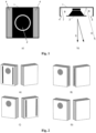
- variations ( Fig. 2 ) of loudspeakers with different constructions of acoustic boxes like: A) with openings in the front near the membrane; B) with openings in the side of the box; C) with openings at the back of the box; and D) closed type.
- the Fig. 3 graph shows the simulated frequency response of options A, B, C and D ( Fig. 2) at 1 meter on the driver axis.
- Modification A and B have a higher SPL compared to the frequency response of closed box D.
- the SPL of modification A is highest over a wide range of frequencies, due to the above mentioned fulfilled conditions of mutual coupling effect.
- Fig. 4 is a graph of the simulated SPL and phase versus frequency.
- the mutual coupling effect changes the overall system directivity by summing up waves moving in the same direction.
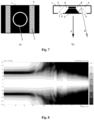
- FIG. 5 is simulations of modifications A and D enclosures for horizontal directivity pattern at 600 Hz (left) and 1000 Hz (right).
- Black - A, Grey - D show that the acoustic box A radiates more forwards than laterally. This results in more directing soundwaves toward the listener and fewer to reflective side surfaces.
- Fig. 6 is defined vertical directivity index (DI) in decibels in relation to frequencies (Black - A, Grey - D).
- DI vertical directivity index
- the vertical plot of the directivity index of the A and D modifications also shows the influence of the coupling effect. Not only is the directivity increased, but the pattern becomes evenly wider over the frequency range and starts narrowing (speaker beaming starts) at higher frequency, thus achieving the goal of having a higher and more even directivity index in as wide a range of frequency as possible.
- Fig. 7 is shown one of the design solutions of an acoustic box 1, with cone speaker 2 which front wave 5 and reflected rear wave 6 coincide over the widest possible frequency range and whose frequency ROI is as uniform as possible over this range.
- the correction of the rear wave phase can be varied in several ways, by changing the area of the front openings 4 and by changing the dimensions of the rear chamber 8.
- the best results were obtained by forming inverted split V-shaped inner wall 7 in the inner 8 part of chamber 1. Inside the box is used a Helmholtz resonator tuned to absorb the rear wave peak of cone speaker 2, by an acoustic filter formed in the rear chamber 3.
- the advantage of this solution is that is obtained a very directive complex system for the whole audible acoustic frequency spectrum.
- This invented directional enclosure can be combined with other frequencies directional modules.
- the invented loudspeaker is combined with other low frequency (LF) dipole module and high frequency compact horn, there is obtained very directive complex system for whole audible acoustic frequency spectrum. This combination leads to significantly more detailed soundstage and better sound resolution when compared to traditional systems.
- LF low frequency
Landscapes
- Health & Medical Sciences (AREA)
- Otolaryngology (AREA)
- Physics & Mathematics (AREA)
- Engineering & Computer Science (AREA)
- Acoustics & Sound (AREA)
- Signal Processing (AREA)
- Details Of Audible-Bandwidth Transducers (AREA)
Priority Applications (1)
| Application Number | Priority Date | Filing Date | Title |
|---|---|---|---|
| EP23173508.5A EP4465657A1 (de) | 2023-05-16 | 2023-05-16 | Richtungslautsprecher |
Applications Claiming Priority (1)
| Application Number | Priority Date | Filing Date | Title |
|---|---|---|---|
| EP23173508.5A EP4465657A1 (de) | 2023-05-16 | 2023-05-16 | Richtungslautsprecher |
Publications (1)
| Publication Number | Publication Date |
|---|---|
| EP4465657A1 true EP4465657A1 (de) | 2024-11-20 |
Family
ID=86387174
Family Applications (1)
| Application Number | Title | Priority Date | Filing Date |
|---|---|---|---|
| EP23173508.5A Pending EP4465657A1 (de) | 2023-05-16 | 2023-05-16 | Richtungslautsprecher |
Country Status (1)
| Country | Link |
|---|---|
| EP (1) | EP4465657A1 (de) |
Cited By (1)
| Publication number | Priority date | Publication date | Assignee | Title |
|---|---|---|---|---|
| US12598408B2 (en) * | 2023-04-14 | 2026-04-07 | Alps Alpine Co., Ltd. | Acoustic apparatus |
Citations (4)
| Publication number | Priority date | Publication date | Assignee | Title |
|---|---|---|---|---|
| US3696886A (en) * | 1968-05-03 | 1972-10-10 | James C Armstrong | Speaker cabinet enclosure and method of tuning thereof |
| US3722616A (en) * | 1970-12-14 | 1973-03-27 | Ltv Altec Inc | Directional loudspeaker system |
| US5552569A (en) * | 1995-03-08 | 1996-09-03 | Sapkowski; Mechislao | Exponential multi-ported acoustic enclosure |
| EP3018915A1 (de) | 2014-11-04 | 2016-05-11 | Dutch & Dutch B.V. | Richtlautsprecher |
-
2023
- 2023-05-16 EP EP23173508.5A patent/EP4465657A1/de active Pending
Patent Citations (4)
| Publication number | Priority date | Publication date | Assignee | Title |
|---|---|---|---|---|
| US3696886A (en) * | 1968-05-03 | 1972-10-10 | James C Armstrong | Speaker cabinet enclosure and method of tuning thereof |
| US3722616A (en) * | 1970-12-14 | 1973-03-27 | Ltv Altec Inc | Directional loudspeaker system |
| US5552569A (en) * | 1995-03-08 | 1996-09-03 | Sapkowski; Mechislao | Exponential multi-ported acoustic enclosure |
| EP3018915A1 (de) | 2014-11-04 | 2016-05-11 | Dutch & Dutch B.V. | Richtlautsprecher |
Cited By (1)
| Publication number | Priority date | Publication date | Assignee | Title |
|---|---|---|---|---|
| US12598408B2 (en) * | 2023-04-14 | 2026-04-07 | Alps Alpine Co., Ltd. | Acoustic apparatus |
Similar Documents
| Publication | Publication Date | Title |
|---|---|---|
| US8428284B2 (en) | Loudspeaker with passive low frequency directional control | |
| US6343134B1 (en) | Loudspeaker and horn with an additional transducer | |
| US20020150270A1 (en) | Sound system having a HF horn coaxially aligned in the mouth of a midrange horn | |
| US20050169493A1 (en) | Loudspeaker array system | |
| US7835537B2 (en) | Loudspeaker including slotted waveguide for enhanced directivity and associated methods | |
| EP2356824B1 (de) | Audiolautsprecheranordnung | |
| US4134471A (en) | Narrow angle cylindrical wave full range loudspeaker system | |
| KR20100066826A (ko) | 지향성 음향 발생장치 및 방법 | |
| EP3058751A1 (de) | Antidiffraktions- und phasenkorrekturstruktur für planare magnetische wandler | |
| JPH05268690A (ja) | 広角度の指向性を有するスピーカ装置 | |
| KR101071963B1 (ko) | 지향성이 향상된 음향 재생 장치 | |
| US6038326A (en) | Loudspeaker and horn with an additional transducer | |
| US20120121118A1 (en) | Slotted waveguide for loudspeakers | |
| US20190058954A1 (en) | Layered speaker assembly | |
| US11082760B2 (en) | Vibration cancelling speaker arrangement | |
| US4437541A (en) | Controlled dispersion speaker configuration | |
| US10123111B2 (en) | Passive cardioid speaker | |
| EP4465657A1 (de) | Richtungslautsprecher | |
| US7426278B2 (en) | Sound device provided with a geometric and electronic radiation control | |
| US7577265B2 (en) | Loudspeaker system providing improved sound presence and frequency response in mid and high frequency ranges | |
| US20170006379A1 (en) | A Sound Diffusion System for Directional Sound Enhancement | |
| US8406445B1 (en) | Loudspeaker system with extended constant vertical beamwidth control | |
| JP6824821B2 (ja) | スピーカー | |
| KR100320054B1 (ko) | 원뿔형반사기/결합기스피커시스템및방법 | |
| US8254614B2 (en) | Horn speaker with hyperbolic paraboloid lens |
Legal Events
| Date | Code | Title | Description |
|---|---|---|---|
| PUAI | Public reference made under article 153(3) epc to a published international application that has entered the european phase |
Free format text: ORIGINAL CODE: 0009012 |
|
| STAA | Information on the status of an ep patent application or granted ep patent |
Free format text: STATUS: THE APPLICATION HAS BEEN PUBLISHED |
|
| AK | Designated contracting states |
Kind code of ref document: A1 Designated state(s): AL AT BE BG CH CY CZ DE DK EE ES FI FR GB GR HR HU IE IS IT LI LT LU LV MC ME MK MT NL NO PL PT RO RS SE SI SK SM TR |
|
| STAA | Information on the status of an ep patent application or granted ep patent |
Free format text: STATUS: REQUEST FOR EXAMINATION WAS MADE |
|
| 17P | Request for examination filed |
Effective date: 20250510 |