EP4465397A1 - Wickelvorrichtung und verfahren zum wickeln eines oder mehrerer streifenförmiger separatoren und elektrodenfolien aneinander - Google Patents
Wickelvorrichtung und verfahren zum wickeln eines oder mehrerer streifenförmiger separatoren und elektrodenfolien aneinander Download PDFInfo
- Publication number
- EP4465397A1 EP4465397A1 EP24175471.2A EP24175471A EP4465397A1 EP 4465397 A1 EP4465397 A1 EP 4465397A1 EP 24175471 A EP24175471 A EP 24175471A EP 4465397 A1 EP4465397 A1 EP 4465397A1
- Authority
- EP
- European Patent Office
- Prior art keywords
- collecting
- strip
- transfer
- winding
- transfer device
- Prior art date
- Legal status (The legal status is an assumption and is not a legal conclusion. Google has not performed a legal analysis and makes no representation as to the accuracy of the status listed.)
- Pending
Links
Images


Classifications
-
- H—ELECTRICITY
- H01—ELECTRIC ELEMENTS
- H01M—PROCESSES OR MEANS, e.g. BATTERIES, FOR THE DIRECT CONVERSION OF CHEMICAL ENERGY INTO ELECTRICAL ENERGY
- H01M10/00—Secondary cells; Manufacture thereof
- H01M10/04—Construction or manufacture in general
- H01M10/0404—Machines for assembling batteries
- H01M10/0409—Machines for assembling batteries for cells with wound electrodes
-
- H—ELECTRICITY
- H01—ELECTRIC ELEMENTS
- H01M—PROCESSES OR MEANS, e.g. BATTERIES, FOR THE DIRECT CONVERSION OF CHEMICAL ENERGY INTO ELECTRICAL ENERGY
- H01M10/00—Secondary cells; Manufacture thereof
- H01M10/04—Construction or manufacture in general
- H01M10/0431—Cells with wound or folded electrodes
-
- H—ELECTRICITY
- H01—ELECTRIC ELEMENTS
- H01M—PROCESSES OR MEANS, e.g. BATTERIES, FOR THE DIRECT CONVERSION OF CHEMICAL ENERGY INTO ELECTRICAL ENERGY
- H01M10/00—Secondary cells; Manufacture thereof
- H01M10/05—Accumulators with non-aqueous electrolyte
- H01M10/058—Construction or manufacture
- H01M10/0587—Construction or manufacture of accumulators having only wound construction elements, i.e. wound positive electrodes, wound negative electrodes and wound separators
-
- B—PERFORMING OPERATIONS; TRANSPORTING
- B65—CONVEYING; PACKING; STORING; HANDLING THIN OR FILAMENTARY MATERIAL
- B65H—HANDLING THIN OR FILAMENTARY MATERIAL, e.g. SHEETS, WEBS, CABLES
- B65H2301/00—Handling processes for sheets or webs
- B65H2301/40—Type of handling process
- B65H2301/41—Winding, unwinding
- B65H2301/413—Supporting web roll
- B65H2301/4135—Movable supporting means
- B65H2301/41354—Movable supporting means moving along a path enclosing a circular area, e.g. turret
-
- B—PERFORMING OPERATIONS; TRANSPORTING
- B65—CONVEYING; PACKING; STORING; HANDLING THIN OR FILAMENTARY MATERIAL
- B65H—HANDLING THIN OR FILAMENTARY MATERIAL, e.g. SHEETS, WEBS, CABLES
- B65H2801/00—Application field
- B65H2801/72—Fuel cell manufacture
-
- Y—GENERAL TAGGING OF NEW TECHNOLOGICAL DEVELOPMENTS; GENERAL TAGGING OF CROSS-SECTIONAL TECHNOLOGIES SPANNING OVER SEVERAL SECTIONS OF THE IPC; TECHNICAL SUBJECTS COVERED BY FORMER USPC CROSS-REFERENCE ART COLLECTIONS [XRACs] AND DIGESTS
- Y02—TECHNOLOGIES OR APPLICATIONS FOR MITIGATION OR ADAPTATION AGAINST CLIMATE CHANGE
- Y02E—REDUCTION OF GREENHOUSE GAS [GHG] EMISSIONS, RELATED TO ENERGY GENERATION, TRANSMISSION OR DISTRIBUTION
- Y02E60/00—Enabling technologies; Technologies with a potential or indirect contribution to GHG emissions mitigation
- Y02E60/10—Energy storage using batteries
-
- Y—GENERAL TAGGING OF NEW TECHNOLOGICAL DEVELOPMENTS; GENERAL TAGGING OF CROSS-SECTIONAL TECHNOLOGIES SPANNING OVER SEVERAL SECTIONS OF THE IPC; TECHNICAL SUBJECTS COVERED BY FORMER USPC CROSS-REFERENCE ART COLLECTIONS [XRACs] AND DIGESTS
- Y02—TECHNOLOGIES OR APPLICATIONS FOR MITIGATION OR ADAPTATION AGAINST CLIMATE CHANGE
- Y02P—CLIMATE CHANGE MITIGATION TECHNOLOGIES IN THE PRODUCTION OR PROCESSING OF GOODS
- Y02P70/00—Climate change mitigation technologies in the production process for final industrial or consumer products
- Y02P70/50—Manufacturing or production processes characterised by the final manufactured product
Definitions
- the present invention relates to a winding apparatus for winding one or more strip-like separators and electrode foils to each other and a method for winding one or more strip-like separators and electrode foils to each other.
- the present invention is particularly usable in a process for making electrochemical cells, for example secondary electrochemical cells, comprising electrodes separated from each other by a dielectric separator.
- the present invention can also be used in a process to make electrical capacitors.
- One type of electrochemical cell known as a jelly roll or Swiss roll, involves a strip-like separator being interposed between two electrode foils, specifically an anode and a cathode, and the multilayer consisting of the separator and electrode foils being wound to form a cylindrical or quasi-cylindrical electrochemical cell.
- winding apparatuses with a winding mandrel that can be rotated about its own longitudinal axis are used to make this type of electrochemical cell. Free ends of the electrode foils and the strip-like separator are coupled to the winding mandrel, which is rotated about its longitudinal axis, causing the electrode foils and separator to wind around each other and onto the winding mandrel.
- the strip-like separator and electrode foils are continuously unwound from respective reels.
- each collecting roller of an assembly is arranged tangential to a respective transfer roller (moving the axes of rotation of two collecting rollers) and the oscillating frame is driven to move the four transfer rollers at the same speed as the rotary member.
- the collecting rollers remain tangential to the respective transfer rollers and the sections of electrode foils and of separator strips are transferred to the respective collecting rollers.
- the axes of rotation of two collecting rollers are moved to arrange the four collecting rollers around the winding mandrel.
- the oscillating frame is returned to its initial position by performing a return stroke.
- the winding mandrel then starts winding the electrode foils and separator strips by taking them from the four collecting rollers arranged around it, and when the oscillating frame returns to its initial position, it is activated on a new collecting assembly.
- a collecting assembly receives respective sections of electrode foils and separator strips, and the corresponding winding mandrel receives these sections of electrode foils and separator strips from the collecting rollers and winds them together.
- the Applicant has noted that there is a growing need to increase the production rate of electrochemical cells, in particular to increase the number of electrochemical cells produced in a unit of time.
- the collecting rollers of a collecting assembly are basically inactive, in the sense that they are not performing any action on the sections of electrode foils and separator strips.
- the Applicant found that by transferring electrode foils and separator strips from transfer devices to collecting devices of the same collecting assembly in such a way that the electrode foils and separator strips are transferred at different and successive times to the respective collecting devices of the same collecting assembly, it would be possible to temporally couple each collecting device to the respective transfer device one after the other without the need to reconfigure the collecting devices according to a configuration allowing them to be coupled to the transfer devices at the same time.
- the Applicant has verified that this eliminates the aforementioned preparation time as the collecting devices of each collecting assembly are arranged in the same pattern both during the transfer of the electrode foils and the separator strips from the transfer devices to the collecting devices, and during the unwinding of the electrode foils and separator strips from the collecting devices and subsequent winding around the winding mandrel.
- the present invention therefore relates, in a first aspect thereof, to a winding apparatus for winding one or more strip-like separators and electrode foils together.
- a loading station is provided.
- each transfer device is configured to receive and transfer an electrode foil or strip-like separator.
- the transfer devices are arranged in sequence along a loading path in said loading station.
- a first collecting assembly is movable along said loading path and comprising a support structure on which a plurality of collecting devices are arranged.
- each collecting device is rotatable about its own winding axis relative to the support structure and is configured to receive from a transfer device an electrode foil or a strip-like separator.
- said support structure rotates about its own support axis at least when it is in said loading station to have each collecting device face, one after the other, a corresponding transfer device.
- the present invention relates, in a second aspect thereof, to a method for winding one or more strip-like separators and electrode foils together.
- the strip-like elements each of which defining an electrode foil or a strip-like separator is provided to feed the strip-like elements each of which defining an electrode foil or a strip-like separator to respective transfer devices.
- each strip-like element is provided to transfer each strip-like element in separate and successive time instants from the respective transfer device to a respective first collecting assembly.
- each collecting device of the first collecting assembly is provided to unwind the strip-like elements from each collecting device of the first collecting assembly and wind them onto a winding mandrel.
- the Applicant has verified that by transferring in separate and successive time instants each strip-like element from the respective transfer device to a respective collecting device, during the time required for the support structure to travel along the loading path, it is possible to face all the collecting devices to a respective transfer device and thus transfer strip-like elements to all collecting devices of a collecting assembly.
- Strip-like element means an electrode foil or separator strip.
- Electrode foil means a strip or foil having two much larger dimensions than a third dimension.
- the electrode foil can be a monolithic strip (or foil) or a strip consisting of a plurality of layers joined together of identical or different materials, possibly coated at least partially with an active electrode material.
- the electrode foil also has characteristics that allow a certain amount of bending during its use.
- a “separator strip” is defined as a strip with one dimension much larger than two further dimensions, where a first dimension of those two further dimensions is much larger than a second dimension of those two further dimensions.
- the strip may be monolithic or made up of a plurality of layers joined together of identical or different materials.
- the separator tape is made of or coated with dielectric material. The separator strip also has characteristics that allow a certain amount of bending during its use.
- Active electrode material may be an anodic or cathodic material and may comprise, by way of example, in the case of anodic material, graphite or other carbonaceous materials or silicon-based materials and, in the case of cathodic material, lithium oxide, nickel, manganese, cobalt, aluminium or lithium and iron phosphate-based materials.
- Contact between a collecting device and a transfer device means that the collecting device contacts the transfer device either directly or by interposing a strip-like element between the collecting device and the transfer device.
- Collecting device facing a transfer device means that the collecting device is placed in correspondence and preferably in contact with the transfer device.
- the present invention can have at least one of the preferred features described below. Such features may be present individually or in combination with each other, unless expressly stated otherwise, both in the winding apparatus and in the method for winding of the present invention.
- a plurality of collecting assemblies is preferably provided.
- the winding axes of the collecting devices rotate about said support axis of the support structure at least when they are in said loading station.
- the winding axes of the collecting devices rotate about said support axis of the support structure drawn in rotation by the rotation of the support structure about its support axis.
- each collecting device comprises a winding pivot crossed by the winding axis of the collecting device.
- each winding pivot is connected to the support structure.
- each collecting device comprises a collecting roller that can be rotated about a respective winding pivot.
- each winding pivot is crossed by a respective winding axis and runs parallel to the respective winding axis.
- the winding axes of the collecting devices of the first collecting unit are parallel to each other.
- the support structure is configured to support each collecting device and to rotate it about the support axis of the support structure.
- the support axis of the support structure is parallel to the winding axes of the collecting devices.
- the winding axes of the collecting devices are arranged around the support axis of the support structure.
- the winding axes of the collecting devices are arranged along a circumference surrounding the support axis of the support structure.
- the winding axes of the collecting devices are arranged along a circumference having its centre crossed by the support axis of the support structure.
- the winding axes are angularly spaced around the support axis of the support structure.
- the winding axes are angularly spaced apart by angular distances that remain unchanged at least when the support structure travels along the loading path.
- the winding axes are angularly spaced apart by angular distances that remain unchanged.
- the rotation of the support structure about the support axis takes place, at least in the loading station, without varying the angular distances between the winding axes.
- the support structure To enable the support structure to travel along the loading path, it is preferably rotatable about a transport axis.
- said support structure rotates about its own support axis and about said transport axis at least when the collecting assembly travels along the loading path.
- each collecting device rotates simultaneously about its own winding axis, about the support axis of the support structure and about the transport axis.
- the transport axis is preferably parallel to the support axis of the support structure.
- the transport axis is preferably separate and spaced apart from the support axis of the support structure.
- the rotation of the support structure about the transport axis defines an essentially circular path for the support structure. A portion of this essentially circular path defines the loading path.
- the loading path is a path that runs along an arc of circumference.
- the transport axis is parallel and crossed by a motorised transport shaft.
- the support structure is connected to the motorised transport shaft so that it can travel along the loading path.
- the transfer devices are arranged along the arc of circumference that defines the loading path.
- the loading station comprises an adhesive tape feeder.
- the adhesive tape feeder comprises a reel of adhesive tape and a knife.
- the rotation of the support structure about the support axis (which results in the rotation of the winding axes about the support axis), faces the collecting devices one after the other to the transfer devices.
- the rotation of the collecting devices about their winding axes allows the strip-like elements to be wound around the collecting devices.
- the other collecting devices of said first collecting assembly are not facing any transfer device.
- each transfer device is rotatable about its own transfer axis.
- each transfer axis is parallel to the winding axes of the collecting devices.
- each transfer device comprises at least one transfer roller rotatable about a transfer pivot.
- the transfer pivot is parallel to the winding axes.
- each transfer device is configured to retain and pull at least a portion of the strip-like element and to deliver the portion of the strip-like element to a respective collecting device.
- each transfer device may include a suction device that can be activated on a portion of the strip-like element.
- a cutting device is provided at each transfer device to cut the incoming strip-like element at the transfer device and make a section of strip-like element that will be transferred to the collecting device.
- each collecting device comprises a retaining device for retaining at least a portion of strip-like element transferred from the transfer device and allow the strip-like element to be wound onto the collecting device.
- the transfer devices do not make movements in the direction of the loading path.
- a portion of adhesive tape is fed to a collecting device and partially overlapped with an end portion of the strip-like element that will be transferred to that collecting device.
- said portion of adhesive tape is fed to a single collecting device.
- such a strip-like element is a separator strip.
- At least one winding mandrel is provided for winding electrode foils and strip-like separators received from said plurality of collecting devices together.
- each collecting assembly comprises a winding mandrel.
- the winding mandrel has the function of winding the strip-like elements wound onto the collecting devices of the same collecting assembly together and forming a jelly roll winding.
- said collecting devices are arranged around said winding mandrel at least when the collecting assembly travels along the loading path.
- the winding mandrel can be rotated about a forming axis parallel to the winding axes of the collecting devices and crossed by the support axis of the support structure.
- This forming axis preferably coincides with the support axis of the support structure.
- the unwinding path is subsequent to the loading path.
- the unwinding path is one that runs along an arc of a circle.
- a portion of the essentially circular path determined by the rotation of the support structure around the transport axis defines the unwinding path.
- the strip-like elements are transferred from the collecting devices to the winding mandrel and are wound around the winding mandrel.
- the collecting devices are arranged and configured to transfer electrode foils and strip-like separators to said winding mandrel as they traverse the unwinding path.
- the winding mandrel can comprise two half-parts that can be moved towards and away from each other to enable the retention of free ends of the strip-like elements the during jelly roll winding of the strip-like elements.
- the strip-like elements wound around the winding mandrel are extracted from the winding mandrel and transferred to subsequent processing stations.
- the first collecting assembly comprises four collecting devices.
- the four collecting devices are angularly equidistant around the support axis of the support structure.
- a plurality of collecting assemblies is preferably provided, each of which is movable along said loading path and each of which comprises a respective support structure on which a plurality of collecting devices is arranged.
- each collecting device of a collecting assembly is rotatable about its own winding axis relative to the support structure and is configured to receive from a transfer device an electrode foil or a strip-like separator.
- each collecting assembly rotates about its own support axis at least when it is in said loading station to have each collecting device face, one after the other, a corresponding transfer device.
- each collecting assembly of said plurality of collecting assemblies is structurally and functionally the same as the first collecting assembly.
- the collecting assemblies are arranged around the transport axis and are equidistant from the transport axis.
- the angular distance separating any two adjacent collecting assemblies remains unchanged during the rotation of the collecting assemblies about the transport axis.
- a number of collecting assemblies equal to the number of transfer devices are simultaneously present in the loading station.
- each transfer device is faced by a corresponding collecting device; the collecting devices faced by the transfer devices belong to different collecting assemblies.
- the action of transferring in separate and subsequent time instants each strip-like element from the respective transfer device to a respective collecting device of the first collecting assembly comprises moving the first collecting assembly along a loading path along which the transfer devices are arranged in sequence and having each collecting device of the first collecting assembly face, one after the other, a corresponding transfer device.
- moving a collecting assembly along the loading path includes rotating all the collecting assemblies about the transport axis.
- the rotation of all the collecting assemblies about the transport axis is carried out with continuity, i.e. a continuous, uninterrupted rotation.
- the rotation of all the collecting assemblies about the transport axis is implemented step-by-step, i.e. with a rotation involving continuous movements alternating with breaks in motion.
- the transfer device first placed along the loading path transfers a strip-like element to a first collecting device of a collecting assembly
- no strip-like element has yet been transferred to the other collecting devices of the same collecting assembly.
- the action of transferring each strip-like element from the respective transfer device to a respective collecting device of the first collecting assembly comprises rotating said respective collecting device about its own winding axis while facing the respective transfer device.
- the action of having each collecting device of the first collecting assembly face, one after the other, a corresponding transfer device comprises completing the transfer of a strip-like element from a transfer device to a collecting device of the first collecting assembly before having a further collecting device of the first collecting assembly face a further transfer device.
- the transfer device that is placed second along the loading path transfers a strip-like element to a second collecting device of a collecting assembly
- only the first collecting device of that collecting assembly has a strip-like element wound around it, while no strip-like element has yet been transferred to the other collecting devices of the same collecting assembly.
- the transfer device that is placed third along the loading path transfers a strip-like element to a third collecting device of a collecting assembly
- only the first and second collecting devices of that collecting assembly have a respective strip-like element wound while no strip-like element has yet been transferred to the other collecting devices of the same collecting assembly.
- the transfer device that is placed fourth along the loading path transfers a strip-like element to a fourth collecting device of a collecting assembly
- all the other collecting devices of the same collecting assembly have a respective strip-like element wound around it.
- the action of having each collecting device of the first collecting assembly face a corresponding transfer device one after the other comprises rotating all the collecting devices of the first collecting assembly about the support axis of the support structure when the first collecting assembly traverses the loading path.
- rotating all the collecting devices of the first collecting assemblies about the support axis of the support structure is implemented at least when the first collecting assembly moves between one transfer device and the next transfer device.
- a strip-like element is to be transferred from a different transfer device to a collecting device of a further collecting assembly.
- the transfer device that is placed first along the loading path transfers a strip-like element to a collecting device of a first collecting assembly
- the transfer device that is placed second along the loading path transfers a strip-like element to a collecting device of a second collecting assembly.
- the transfer device that is placed second along the loading path transfers a strip-like element to a collecting device of a second collecting assembly
- the transfer device that is placed third along the loading path transfers a strip-like element to a collecting device of a third collecting assembly.
- the transfer device that is placed third along the loading path transfers a strip-like element to a collecting device of a third collecting assembly
- the transfer device that is placed fourth along the loading path transfers a strip-like element to a collecting device of a fourth collecting assembly.
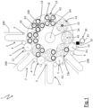
- the apparatus 1 is preferably used to wind one or more strip-like separators and electrode foils together, which are used to make electrochemical cells, e.g. secondary electrochemical cells.
- the apparatus 1 comprises a plurality of feeders 2 for feeding strip-like elements 100 each intended to form an anode 101, a cathode 102 or a strip-like separator 103 of dielectric material.
- the strip-like elements 100 are fed by the plurality of feeders 2 in the form of continuous strips.
- the feeders 2 are connected to coils (not illustrated) onto each of which a respective strip-like element 100 is wound.
- Each feeder 2 comprises a return roller 3 and an unwinding roller 4.
- the function of the return roller 3 is to accompany the strip-like element 100 towards the unwinding roller 4, causing the strip-like element to take a festoon-like path.
- Each return roller 3 can be moved to increase or decrease the length of this festoon, so as to create a buffer for the strip-like element fed to the unwinding roller 4.
- the apparatus 1 comprises a plurality of transfer devices 5. Each transfer device 5 is fed with a strip-like element 100 from the respective feeder 2. As depicted in Figures 1 and 2 , the unwinding roller 4 of each feeder 2 feeds a respective strip-like element 100 to a corresponding transfer device 5. Each transfer device 5 is rotatable about its own transfer axis A1. The transfer axes A1 of all the transfer devices 5 are parallel to each other.
- Each transfer device 5 comprises a transfer roller 6 rotatable about a transfer pivot 7 coinciding with the transfer axis A1.
- the transfer roller 6 comprises an outer surface 8 onto which the strip-like element 100 is fed by the unwinding roller 4.
- each transfer device 5 comprises a suction device 9 that can be activated on a portion of the strip-like element 100 to retain it.
- the suction device 9 can for example be formed by a plurality of suction devices 10 distributed on the outer surface 8 of the transfer roller 6.
- the suction device 9 has the task of retaining the strip-like element 100 during the rotation of the transfer device 5.
- the apparatus 1 comprises a cutting device 11 for cutting the strip-like element being transferred from the transfer device 5.
- the cutting device 11 can be a cutter or a rotary blade 12 (as depicted in Figure 2 ) configured to cut a strip-like element 100 and make a section of it.
- the cutting device 11 is active on the transfer device 5, and in particular on the transfer roller 6, and is located downstream of the unwinding roller 4.
- the cutting device 11 can be placed upstream of the unwinding roller 4 to feed the transfer device 5 directly with sections of strip-like elements 100.
- An adhesive tape feeder 30 (illustrated in Figure 1 ) is placed at a transfer device 5.
- the adhesive tape feeder 30 comprises a reel of adhesive tape 31 and a knife 32.
- the transfer devices 5 are arranged one after the other in a loading station LS and along a loading path LP.
- Each transfer device 5 is translatable perpendicular to the loading path LP. Each transfer device 5 is not movable in any other direction.
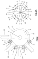
- the apparatus 1 also comprises a plurality of collecting assemblies 13, including a first collecting assembly 13a shown in Figure 2A .
- the collecting assemblies 13 are identical to each other and, therefore, what is described below in relation to the first collecting assembly 13a is valid for any collecting assembly 13.
- the first collecting assembly 13a comprises a plurality of collecting devices 14.
- the number of collecting devices 14 is equal to the number of transfer devices 5.
- Each collecting device 14 is rotatable about its own winding axis A2.
- the winding axes of all the collecting devices 14 are parallel to each other.
- Each collecting device comprises a collecting roller 15 rotatable about a winding pivot 16 coinciding with the winding axis A2.
- the collecting roller 16 comprises an outer surface 17 configured to receive a section of strip-like element 100 on it.
- each collecting device 14 comprises a retaining device 18 that can be activated on a portion of the strip-like element 100 to retain it.
- the retaining device 18 can, for example, be formed by one or more suction devices 19 (only one suction device 19 is shown in Figure 2A ) placed on the outer surface 17 of the collecting roller 15.
- the suction device 9 has the task of retaining the strip-like element 100 during the rotation of the transfer device 5.
- the first collecting assembly 13a further comprises a support structure 20 for the collecting devices 14.
- the support structure 20 can be a plate or disc 21 (as shown in the accompanying figures) or a frame of any shape.
- the collecting devices 14 are rotatably constrained to the support structure 20 at the winding axes A2.
- the winding axes A2 are motorised to be able to rotate relative to the support structure 20.
- An electric motor (not shown) can be provided for each collecting device 14 or a single electric motor that drives all the collecting devices 14 in rotation relative to the support structure 14.
- the collecting rollers 15 are hinged to the support structure 14 at the respective winding pivots 16.
- the winding axes A2 are angularly distanced from each other by their respective angular distances AD, which always remain constant. These angular distances AD are identical to each other.
- the first collecting assembly 13a comprises a winding mandrel 22 rotatably mounted relative to the support structure 20 around a forming axis A3.
- the winding mandrel 22 is rotatably mounted on the support structure 20 around the forming axis A3.
- the rotation of the winding mandrel 22 around the forming axis A3 is driven by an electric motor (not shown).
- the forming axis A3 is parallel to the winding axes A2.
- the winding mandrel 22 comprises two half-parts 23 that can be moved towards and away from each other to allow the free end of a strip-like element 100 to be inserted between the two half-parts 23 (by moving the two half-parts 23 apart) and retained between them (by bringing the two half-parts 23 together).
- Each support structure 20 is rotatably mounted around a transport axis A4.
- the apparatus 1 comprises a motorised transport shaft 24 crossed by the transport axis A4.
- the support structures 20 are rotationally constrained to the transport shaft 24 and spaced from the transport axis A4.
- the support structures 20 are constrained to the transport shaft 24 by a transport structure 25, which can have any structure suitable for the purpose.
- the support structures 20 are constrained to the transport shaft 24 by a disc-shaped plate 26 onto which the transport shaft 24 is keyed.
- the transport axis A4 is parallel to the winding axes A2 of the collecting devices.
- the support structures 20 are also rotatably constrained to the support structure 25 so that they can rotate about their own support axis A5 while rotating about the transport axis A4.
- Each support structure 20 comprises a support pivot 27 hinged to the transport structure 25 and motorised.
- the support axis A5 passes through the support pivot 27.
- the support axis A5 is parallel to the winding axes A2.
- the support axis A5 coincides with the forming axis A3 of the winding mandrel 22.
- Each collecting device 14 is therefore rotatable about its own winding axis A2, about the support axis A5 of the respective support structure 20 and about the transport axis A4.
- the support structures 20 rotate continuously about the transport axis A4 following a substantially circular path.
- the support structures 20 follow the loading path LP.
- the support structures 20 While traversing the loading path LP, the support structures 20 rotate continuously about the support axis A5.
- the collecting devices 14 While traversing the loading path LP, the collecting devices 14 rotate about the respective winding axes A2.
- the transfer devices 5 rotate about the transfer axes A1.
- the strip-like elements 100 are transferred, cut into sections, to the collecting devices 14 of a collecting assembly 13.
- Each transfer device 5 transfers a section of strip-like element 100 to a single collecting device 14 of a collecting assembly 13.
- the transfer of the strip-like elements 100 to the respective collecting devices 14 of the same collecting assembly 13 occurs at different and successive times during the loading path LP. In other words, the transfer of the strip-like elements 100 to the respective collecting devices 14 of the same collecting assembly 13 does not take place simultaneously.
- the transfer of a section of strip-like element 100 from a transfer device 5 to a collecting device 14 occurs by rotation of the collecting device 14 about its winding axis A2 and, simultaneously, about the transfer axis A1 of the transfer device 5.
- the four collecting devices 14 are, respectively, a first collecting device 14a, a second collecting device 14b, a third collecting device 14c and a fourth collecting device 14d.
- the four transfer devices 5 are, respectively, a first transfer device 5a, a second transfer device 5b, a third transfer device 5c and a fourth transfer device 5d.
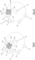
- the first collecting assembly 13a rotates about the transport axis A4
- the first collecting assembly 13a reaches the loading station LS ( Figure 3 ).
- the rotation of the first collecting assembly 13a about the transport axis A4 occurs in a first angular direction F1 (clockwise looking at Figure 3 ).
- the support structure 20 rotates about the support axis A5. This rotation occurs in a second angular direction F2 (anticlockwise looking at Figure 3 ) opposite the first angular direction F1.
- the first collecting device 14a rotates about its winding axis A2 in the first angular direction F1. As soon as the first collecting device 14a faces the first transfer device 5a, making contact with it ( Figure 3 ), the transfer of a first section of strip-like element 100 to the first collecting device 14 begins.
- the first transfer device 5a is fed with the strip-like element 100 and rotates about its transfer axis A1 in the second angular direction F2. This rotation brings a free end of the strip-like element 100 into contact with the first collecting device 14a.
- the retaining device 18 of the first collecting device 14a retains the free end of the strip-like element 100.
- a portion of adhesive tape is cut from the reel of adhesive tape 31 by the knife 32 and fed to the first collecting device 14a and partially overlapped on the free end of the strip-like element 100.
- the rotation of the first collecting device 14a and the first transfer device 5a implements a winding of the strip-like element 100 onto the first collecting device 14a.
- This strip-like element 100 is a separator strip.
- the rotation about the transport axis A4 of the first collecting assembly 13a leads the first collecting assembly to traverse the loading path LP.
- the first collecting device 14a continues to remain in contact with the first transfer device 5a ( Figure 4 ).
- the first collecting device 14a continues to rotate about its own winding axis A2.
- the support structure 20 continues to rotate about its own support axis A5.
- the first transfer device 5a continues to rotate about its own transfer axis A1.
- the rotation of the support structure 20 about the support axis A5 and about the transport axis A4 has the effect that the first collecting device 14a (and in particular its winding axis A2) rotates about the transfer axis A1 of the first transfer device 5a.
- the first transfer device 5a translates away from the transport axis A4 (as shown in Figure 4 ). This translation is of such a magnitude that the contact between the first collecting device 14a and the first transfer device 5a is not removed.
- the further rotation about the transport axis A4 of the first collecting assembly 13a leads the first collecting assembly to travel further along the loading path LP.
- the first collecting device 14a continues to remain in contact with the first transfer device 5a ( Figure 5 ).
- the first collecting device 14a continues to rotate about its own winding axis A2.
- the support structure 20 continues to rotate about its own support axis A5.
- the first transfer device 5a continues to rotate about its own transfer axis A1.
- the rotation of the support structure 20 about the support axis A5 and about the transport axis A4 has the effect that the first collecting device 14a (and in particular its winding axis A2) continues to rotate about the transfer axis A1 of the first transfer device 5a.
- the first transfer device 5a translates towards the transport axis A4 (as shown in Figure 5 ). This translation is of such a magnitude that it returns the first transfer device 5a to its initial position.
- the cutting device 11 cuts the strip-like element 100 longitudinally, producing a section of strip-like element 100.
- the winding of the section of strip-like element 100 onto the first collecting device 14a is completed.
- the first collecting device 14a is still in contact with the first transfer device 5a ( Figure 5 ).
- the rotation of the support structure 20 about the support axis A5 and about the transport axis A4 breaks contact between the first collecting device 14a and the first transfer device 5a.
- the winding axis A2 of the first collecting device 14a is rotated through an angle comprised between 80° and 120° about the transfer axis A1 of the first transfer device 5a.
- Figure 6 schematically illustrates the instant in which the second transfer device 5b is moved away from the transport axis A4 with the second collecting device 14b in contact with the second transfer device 5b. Note that during the winding of a section of strip-like element 100 onto the second collecting device 14b, a section of strip-like element 100 has already been wound onto the first collecting device 14a.
- the strip-like element 100 transferred to the second collecting device 14b is an electrode foil.
- Figure 7 schematically illustrates the instant when the third transfer device 5c makes contact with the third collecting device 14c.
- Figure 8 schematically illustrates the instant when the third transfer device 5c is moved away from the transport axis A4 with the third collecting device 14c in contact with the third transfer device 5c. Note that during the winding of a section of strip-like element 100 onto the third collecting device 14c, a section of strip-like element 100 has already been wound onto the first collecting device 14a and the second collecting device 14b.
- the strip-like element 100 transferred to the third collecting device 14c is a separator tape.
- Figure 9 schematically illustrates the instant when the fourth transfer device 5d is moved away from the transport axis A4 with the fourth collecting device 14d in contact with the fourth transfer device 5d.
- Figure 10 schematically illustrates the instant in which a section of strip-like element 100 has been completely wrapped around the fourth collecting device 14d. Note that during the winding of a section of strip-like element 100 onto the fourth collecting device 14d, a section of strip-like element 100 has already been wound onto the first collecting device 14a, the second collecting device 14b and the third collecting device 14c.
- the strip-like element 100 transferred to the fourth collecting device 14d is an electrode foil.
- the respective support structure 20 performs a rotation of 360° about the support axis A5.
- the respective support structure 20 completes a rotation of 360° about the support axis A5. While traversing the loading path LP, each support structure 20 completes a rotation of 360° about the support axis A5.
- the sections of strip-like element 100 wound onto the collecting devices 14 are unwound from the latter and wound around the winding mandrel 22.
- the support structure 20 rotates about the transport axis A4.
- the collecting devices 14 rotate about their winding axes A2 and the winding mandrel 22 rotates about the forming axis A3.
- the portion of adhesive tape not overlapping the free end of the strip-like element 100 carried by the first collecting device 14a is fixed to keep the strip-like elements 100 wound onto each other.
- the rotation of the support structure 20 about the transport axis A4 causes the first collecting assembly 13a to traverse an extraction path EP (illustrated in Figure 2 ) that follows the unwinding path UP. While traversing the extraction path EP the strip-like elements 100 wrapped together around the winding mandrel 22 are extracted from the winding mandrel 22 and transferred to subsequent processing stations.
- an extraction path EP illustrated in Figure 2
- each transfer device 5 operates on a collecting device 14 of a respective collecting assembly 13 in the manner described above. Therefore, all the transfer devices 5 operate simultaneously on collecting devices 14 each of the collecting devices 14 belonging to a different collecting assembly 13.
Landscapes
- Engineering & Computer Science (AREA)
- Manufacturing & Machinery (AREA)
- Chemical & Material Sciences (AREA)
- Chemical Kinetics & Catalysis (AREA)
- Electrochemistry (AREA)
- General Chemical & Material Sciences (AREA)
- Secondary Cells (AREA)
Applications Claiming Priority (1)
| Application Number | Priority Date | Filing Date | Title |
|---|---|---|---|
| IT102023000009894A IT202300009894A1 (it) | 2023-05-16 | 2023-05-16 | Apparato di avvolgimento e metodo per avvolgere tra loro uno o più separatori nastriformi e lamine di elettrodo |
Publications (1)
| Publication Number | Publication Date |
|---|---|
| EP4465397A1 true EP4465397A1 (de) | 2024-11-20 |
Family
ID=87418692
Family Applications (1)
| Application Number | Title | Priority Date | Filing Date |
|---|---|---|---|
| EP24175471.2A Pending EP4465397A1 (de) | 2023-05-16 | 2024-05-13 | Wickelvorrichtung und verfahren zum wickeln eines oder mehrerer streifenförmiger separatoren und elektrodenfolien aneinander |
Country Status (2)
| Country | Link |
|---|---|
| EP (1) | EP4465397A1 (de) |
| IT (1) | IT202300009894A1 (de) |
Citations (3)
| Publication number | Priority date | Publication date | Assignee | Title |
|---|---|---|---|---|
| EP3333954A1 (de) * | 2015-08-05 | 2018-06-13 | Kaido Manufacturing CO., LTD. | Wicklungsvorrichtung |
| WO2023275909A1 (en) * | 2021-07-02 | 2023-01-05 | P.I.T. S.R.L. | Method and machine for manufacturing electrical energy storage devices |
| WO2023275908A1 (en) * | 2021-07-02 | 2023-01-05 | P.I.T. S.R.L. | Method and machine for manufacturing electrical energy storage devices |
-
2023
- 2023-05-16 IT IT102023000009894A patent/IT202300009894A1/it unknown
-
2024
- 2024-05-13 EP EP24175471.2A patent/EP4465397A1/de active Pending
Patent Citations (3)
| Publication number | Priority date | Publication date | Assignee | Title |
|---|---|---|---|---|
| EP3333954A1 (de) * | 2015-08-05 | 2018-06-13 | Kaido Manufacturing CO., LTD. | Wicklungsvorrichtung |
| WO2023275909A1 (en) * | 2021-07-02 | 2023-01-05 | P.I.T. S.R.L. | Method and machine for manufacturing electrical energy storage devices |
| WO2023275908A1 (en) * | 2021-07-02 | 2023-01-05 | P.I.T. S.R.L. | Method and machine for manufacturing electrical energy storage devices |
Also Published As
| Publication number | Publication date |
|---|---|
| IT202300009894A1 (it) | 2024-11-16 |
Similar Documents
| Publication | Publication Date | Title |
|---|---|---|
| EP2569816B1 (de) | Apparatus und verfahren für die herstellung von energiespeichervorrichtungen | |
| US20200365930A1 (en) | Method and device for assembling electrodes | |
| CN102017242B (zh) | 电极片的制造方法和制造装置 | |
| JP5108917B2 (ja) | 巻回素子の製造装置 | |
| JP2009252425A (ja) | 捲回電極体の製造方法および電極巻取装置 | |
| CN112467229A (zh) | 电芯卷绕装置及方法 | |
| US20240313250A1 (en) | Method and machine for manufacturing electrical energy storage devices | |
| CN115703602A (zh) | 用于电能存储装置的生产的卷绕材料条的设备和相关方法 | |
| CN103247826A (zh) | 卷绕装置 | |
| CN111146506A (zh) | 电芯卷绕装置及方法 | |
| EP4465397A1 (de) | Wickelvorrichtung und verfahren zum wickeln eines oder mehrerer streifenförmiger separatoren und elektrodenfolien aneinander | |
| EP4465398A1 (de) | Vorrichtung und verfahren zum wickelen von einem oder mehreren streifenförmigen separatoren und elektrodenfolien | |
| US4930327A (en) | Battery core wrapping method and apparatus | |
| CN216140947U (zh) | 一种放卷机构、卷绕机 | |
| EP4441819B1 (de) | Vorrichtung zur herstellung eines elektrodenstreifens für elektrische energiespeicher | |
| CN102844257B (zh) | 卷绕方法和装置 | |
| CN117597806A (zh) | 用于制造电能储存装置的方法和机器 | |
| WO2025057028A1 (en) | Method and apparatus for winding electrode foils and one or more separator tapes together for the production of electrochemical cells | |
| WO2025057030A1 (en) | Apparatus and method for winding electrode foils and one or more separator tapes together for the production of electrochemical cells | |
| WO2025057032A1 (en) | Method and apparatus for winding electrode foils and one or more separator tapes together for the production of electrochemical cells | |
| CN115649909A (zh) | 一种放卷机构、卷绕机及电芯卷绕方法 | |
| CN218333927U (zh) | 一种电芯卷绕设备 | |
| CN113903978B (zh) | 多卷电芯卷绕装置 | |
| WO2025257869A1 (en) | Apparatus for forming a stack of electrodes for use in manifacturing electric energy storage devices | |
| CN120497473A (zh) | 一种卷针、电芯卷绕机构、电芯卷绕设备及电芯卷绕方法 |
Legal Events
| Date | Code | Title | Description |
|---|---|---|---|
| PUAI | Public reference made under article 153(3) epc to a published international application that has entered the european phase |
Free format text: ORIGINAL CODE: 0009012 |
|
| STAA | Information on the status of an ep patent application or granted ep patent |
Free format text: STATUS: THE APPLICATION HAS BEEN PUBLISHED |
|
| AK | Designated contracting states |
Kind code of ref document: A1 Designated state(s): AL AT BE BG CH CY CZ DE DK EE ES FI FR GB GR HR HU IE IS IT LI LT LU LV MC ME MK MT NL NO PL PT RO RS SE SI SK SM TR |
|
| STAA | Information on the status of an ep patent application or granted ep patent |
Free format text: STATUS: REQUEST FOR EXAMINATION WAS MADE |
|
| 17P | Request for examination filed |
Effective date: 20250508 |