EP4464634A1 - Feeding device and feeding method - Google Patents
Feeding device and feeding method Download PDFInfo
- Publication number
- EP4464634A1 EP4464634A1 EP22955283.1A EP22955283A EP4464634A1 EP 4464634 A1 EP4464634 A1 EP 4464634A1 EP 22955283 A EP22955283 A EP 22955283A EP 4464634 A1 EP4464634 A1 EP 4464634A1
- Authority
- EP
- European Patent Office
- Prior art keywords
- rolling shaft
- information
- surplus
- roll
- length
- Prior art date
- Legal status (The legal status is an assumption and is not a legal conclusion. Google has not performed a legal analysis and makes no representation as to the accuracy of the status listed.)
- Pending
Links
Images


Classifications
-
- B—PERFORMING OPERATIONS; TRANSPORTING
- B65—CONVEYING; PACKING; STORING; HANDLING THIN OR FILAMENTARY MATERIAL
- B65H—HANDLING THIN OR FILAMENTARY MATERIAL, e.g. SHEETS, WEBS, CABLES
- B65H26/00—Warning or safety devices, e.g. automatic fault detectors, stop-motions, for web-advancing mechanisms
- B65H26/06—Warning or safety devices, e.g. automatic fault detectors, stop-motions, for web-advancing mechanisms responsive to predetermined lengths of webs
-
- B—PERFORMING OPERATIONS; TRANSPORTING
- B65—CONVEYING; PACKING; STORING; HANDLING THIN OR FILAMENTARY MATERIAL
- B65H—HANDLING THIN OR FILAMENTARY MATERIAL, e.g. SHEETS, WEBS, CABLES
- B65H26/00—Warning or safety devices, e.g. automatic fault detectors, stop-motions, for web-advancing mechanisms
- B65H26/02—Warning or safety devices, e.g. automatic fault detectors, stop-motions, for web-advancing mechanisms responsive to presence of irregularities in running webs
-
- B—PERFORMING OPERATIONS; TRANSPORTING
- B65—CONVEYING; PACKING; STORING; HANDLING THIN OR FILAMENTARY MATERIAL
- B65H—HANDLING THIN OR FILAMENTARY MATERIAL, e.g. SHEETS, WEBS, CABLES
- B65H19/00—Changing the web roll
- B65H19/10—Changing the web roll in unwinding mechanisms or in connection with unwinding operations
- B65H19/18—Attaching, e.g. pasting, the replacement web to the expiring web
-
- B—PERFORMING OPERATIONS; TRANSPORTING
- B65—CONVEYING; PACKING; STORING; HANDLING THIN OR FILAMENTARY MATERIAL
- B65H—HANDLING THIN OR FILAMENTARY MATERIAL, e.g. SHEETS, WEBS, CABLES
- B65H26/00—Warning or safety devices, e.g. automatic fault detectors, stop-motions, for web-advancing mechanisms
- B65H26/06—Warning or safety devices, e.g. automatic fault detectors, stop-motions, for web-advancing mechanisms responsive to predetermined lengths of webs
- B65H26/063—Warning or safety devices, e.g. automatic fault detectors, stop-motions, for web-advancing mechanisms responsive to predetermined lengths of webs responsive to detection of the trailing edge
-
- B—PERFORMING OPERATIONS; TRANSPORTING
- B65—CONVEYING; PACKING; STORING; HANDLING THIN OR FILAMENTARY MATERIAL
- B65H—HANDLING THIN OR FILAMENTARY MATERIAL, e.g. SHEETS, WEBS, CABLES
- B65H26/00—Warning or safety devices, e.g. automatic fault detectors, stop-motions, for web-advancing mechanisms
- B65H26/06—Warning or safety devices, e.g. automatic fault detectors, stop-motions, for web-advancing mechanisms responsive to predetermined lengths of webs
- B65H26/066—Warning or safety devices, e.g. automatic fault detectors, stop-motions, for web-advancing mechanisms responsive to predetermined lengths of webs responsive to information, e.g. printed mark, on the web or web roll
-
- B—PERFORMING OPERATIONS; TRANSPORTING
- B65—CONVEYING; PACKING; STORING; HANDLING THIN OR FILAMENTARY MATERIAL
- B65H—HANDLING THIN OR FILAMENTARY MATERIAL, e.g. SHEETS, WEBS, CABLES
- B65H2511/00—Dimensions; Position; Numbers; Identification; Occurrences
- B65H2511/10—Size; Dimensions
- B65H2511/11—Length
- B65H2511/114—Remaining length of web roll
-
- B—PERFORMING OPERATIONS; TRANSPORTING
- B65—CONVEYING; PACKING; STORING; HANDLING THIN OR FILAMENTARY MATERIAL
- B65H—HANDLING THIN OR FILAMENTARY MATERIAL, e.g. SHEETS, WEBS, CABLES
- B65H2511/00—Dimensions; Position; Numbers; Identification; Occurrences
- B65H2511/50—Occurence
- B65H2511/51—Presence
- B65H2511/514—Particular portion of element
-
- B—PERFORMING OPERATIONS; TRANSPORTING
- B65—CONVEYING; PACKING; STORING; HANDLING THIN OR FILAMENTARY MATERIAL
- B65H—HANDLING THIN OR FILAMENTARY MATERIAL, e.g. SHEETS, WEBS, CABLES
- B65H2513/00—Dynamic entities; Timing aspects
- B65H2513/10—Speed
-
- B—PERFORMING OPERATIONS; TRANSPORTING
- B65—CONVEYING; PACKING; STORING; HANDLING THIN OR FILAMENTARY MATERIAL
- B65H—HANDLING THIN OR FILAMENTARY MATERIAL, e.g. SHEETS, WEBS, CABLES
- B65H2513/00—Dynamic entities; Timing aspects
- B65H2513/20—Acceleration or deceleration
Definitions
- This application relates to the field of material feeding technologies, and in particular, to a material feeding apparatus and a material feeding method.
- This application provides a material feeding apparatus and a material feeding method, which are conducive to improving production efficiency and the degree of automation.
- this application provides a material feeding apparatus, including: a rolling shaft, a sensor, and a control unit, where a material roll is disposed on the rolling shaft, and the material feeding apparatus is configured to rotate the rolling shaft to convey a material belt in the material roll; the sensor is configured to sense material roll information and send the material roll information to the control unit; and the control unit is configured to control a rotation status of the rolling shaft based on the material roll information.
- An embodiment of this application provides a material feeding apparatus, and the material feeding apparatus includes a rolling shaft, a sensor, and a control unit.
- a material roll is disposed on the rolling shaft, and the material feeding apparatus is configured to rotate the rolling shaft to convey a material belt in the material roll.
- the sensor is configured to sense material roll information and send the material roll information to the control unit.
- the control unit is configured to control the rotation status of the rolling shaft based on the material roll information. In this way, the sensor can be used to detect a status of the material roll and sense the material roll information, thereby helping the control unit control the rotation status of the rolling shaft based on the material roll information, for example, control the rolling shaft to decelerate or stop rotating based on the material roll information. Through provision of the sensor, material roll information can be detected.
- the rotation status of the rolling shaft can be controlled based on the material roll information in a timely manner. Therefore, in the solution of the embodiments of this application, it is unnecessary to manually monitor the status of the material roll in real time, thereby reducing reliance on manual operation and improving the degree of automation. In addition, the rotation status of the rolling shaft can be controlled in a timely manner when the status of the material roll changes, helping improve production efficiency.
- the senor is disposed at an unwinding position of the material belt, and the sensor is configured to sense first information and send the first information to the control unit, where the first information is used to indicate that the transportation of material is interrupted at the unwinding position of the material belt.
- the control unit is configured to control the rolling shaft to stop rotating based on the first information.
- the senor is disposed at an unwinding position of the material belt, and the sensor is configured to sense first information and send the first information to the control unit, where the first information is used to indicate that the transportation of material is interrupted at the unwinding position of the material belt.
- the control unit is configured to control the rolling shaft to stop rotating based on the first information. In this way, interrupted transportation of material can be detected in a timely manner through the sensor, so that when the transportation of material is interrupted, the control unit can control the rolling shaft to stop rotating in a timely manner.
- the rolling shaft can be controlled to stop rotating in a timely manner when the transportation of material is interrupted.
- the rolling shaft can be controlled to stop rotating in a timely manner when the transportation of material is interrupted, thereby reducing deceleration time of the rolling shaft and improving production efficiency.
- the material feeding apparatus further includes a material clamp, where the material clamp moves away from the rolling shaft relative to the sensor along a conveying direction of the material belt.
- the control unit is further configured to control, based on the first information, the material clamp to clamp the material belt tightly to prevent an end of the material belt from sliding out of the material clamp.
- the material clamp can be controlled to clamp the material belt tightly in a timely manner to prevent the end of the material belt from sliding out of the material clamp, thereby avoiding a situation in which material feeding needs to be restarted manually because the end of the material belt slides out, and further helping improve production efficiency and quality.
- the material feeding apparatus further includes a surplus material measurement unit, and the surplus material measurement unit is configured to measure length information of surplus material in the material roll and send the length information of surplus material in the material roll to the control unit.
- the control unit is further configured to control the rolling shaft to decelerate based on the length information of surplus material before controlling the rolling shaft to stop rotating based on the first information.
- the surplus material measurement unit can detect length information of surplus material in the material roll, so that the control unit can control the rolling shaft to decelerate based on the length information of surplus material, so as to control the rolling shaft to stop rotating in a timely manner when the transportation of material is interrupted.
- the surplus material measurement unit includes a first surplus material measurement unit and a second surplus material measurement unit.
- the first surplus material measurement unit moves away from the rolling shaft relative to the sensor along the conveying direction of the material belt, and the first surplus material measurement unit is configured to measure a conveyed length of the material roll and send the conveyed length of the material roll to the control unit.
- the second surplus material measurement unit is configured to measure a current distance between the second surplus material measurement unit and the material roll, and send the current distance of the material roll to the control unit.
- the length information of the surplus material is obtained by using the first surplus material measurement unit and the second surplus material measurement unit respectively.
- accuracy of the obtained length information of surplus material in the material roll can be improved when the length information of surplus material is obtained by using both the first surplus material measurement unit and the second surplus material measurement unit.
- control unit is further configured to: calculate a first surplus material length based on the conveyed length of the material roll; calculate a second surplus material length based on the current distance; control the rolling shaft to decelerate to a first speed in a case that the smaller of the first surplus material length and the second surplus material length has reached a first threshold; and control the rolling shaft to decelerate to a second speed in a case that the larger of the first surplus material length and the second surplus material length has reached the first threshold, where the second speed is less than the first speed.
- control unit calculates the first surplus material length based on the conveyed length detected by the first surplus material measurement unit, and calculates the second surplus material length based on the current distance between the material roll and the second surplus material measurement unit detected by the second surplus material measurement unit, so as to determine how to control the rolling shaft to decelerate based on the first surplus material length and the second surplus material length.
- the solution in this implementation can not only avoid the excessively long deceleration time caused by too early deceleration of the rolling shaft, but also avoid that the rolling shaft cannot stop upon interrupted transportation of material due to too late deceleration of the rolling shaft, thereby achieving both production efficiency and safety.
- the first speed is 50% of a predetermined speed of the rolling shaft
- the second speed is 25% of the predetermined speed of the rolling shaft. This allows for rapid and effective deceleration of the rolling shaft, and also facilitates quick stopping of the rolling shaft.
- the material feeding apparatus further includes a material replacing unit.
- the control unit is configured to control the material replacing unit to replace the material roll based on the first information after the rolling shaft is controlled to stop rotating based on the first information.
- the control unit can control the material replacing unit to replace material, thereby implementing automation of the material replacing when the transportation of material is interrupted, and improving the degree of automation of the material feeding apparatus.
- an operator is not required to enter the replacing platform to replace material, which is conducive to improving production safety.
- the material replacing unit includes an automated guided vehicle.
- the control unit is further configured to, based on the first information, control the automated guided vehicle to take out the rolling shaft and install a new material roll to the rolling shaft. In this way, material can be automatically replaced by using the automated guided vehicle, improving the degree of automation.
- the material replacing unit includes a cylinder and an automated guided vehicle, where the cylinder is connected to the rolling shaft.
- the control unit is further configured to, based on the first information, control the cylinder to push out the rolling shaft and control the automated guided vehicle to install a new material roll to the rolling shaft. In this way, an empty rolling shaft is pushed out by the cylinder, and a new material roll is installed by the automated guided vehicle, implementing automation of material replacement.
- the senor is a photoelectric sensor. In this way, a situation in which transportation material is interrupted can be detected in a timely manner by detecting changes in light flux received by the photoelectric sensor.
- this application provides a material feeding method applied to a material feeding apparatus.
- the material feeding apparatus includes a rolling shaft, a material roll is disposed on the rolling shaft, and the material feeding apparatus is configured to rotate the rolling shaft to convey a material belt in the material roll.
- the material feeding method includes: obtaining material roll information; and controlling a rotation status of the rolling shaft based on the material roll information.
- the obtaining material roll information includes obtaining first information, where the first information is used to indicate that the transportation of material is interrupted at an unwinding position of the material belt.
- the controlling a rotation status of the rolling shaft based on the material roll information includes controlling the rolling shaft to stop rotating based on the first information.
- the material feeding apparatus further includes a material clamp, where the material clamp moves away from the rolling shaft relative to the sensor along a conveying direction of the material belt.
- the method further includes controlling, based on the first information, the material clamp to clamp the material belt tightly to prevent an end of the material belt from sliding out of the material clamp.
- the material feeding apparatus further includes a surplus material measurement unit, where the surplus material measurement unit is configured to measure length information of surplus material in the material roll.
- the method further includes: obtaining the length information of surplus material in the material roll; and controlling the rolling shaft to decelerate based on the length information of surplus material.
- the surplus material measurement unit includes a first surplus material measurement unit and a second surplus material measurement unit, where the first surplus material measurement unit moves away from the rolling shaft relative to the sensor along the conveying direction of the material belt, the first surplus material measurement unit is configured to measure a conveyed length of the material roll, and the second surplus material measurement unit is configured to measure a current distance between the second surplus material measurement unit and the material roll.
- the obtaining the length information of surplus material in the material roll includes: calculating a first surplus material length based on the conveyed length of the material roll; and calculating a second surplus material length based on the current distance.
- the controlling the rolling shaft to decelerate based on the length information of surplus material includes: controlling the rolling shaft to decelerate to a first speed in a case that the smaller of the first surplus material length and the second surplus material length has reached the first threshold; and controlling the rolling shaft to decelerate to a second speed in a case that the larger of the first surplus material length and the second surplus material length has reached the first threshold, where the second speed is less than the first speed.
- the first speed is 50% of a predetermined speed of the rolling shaft
- the second speed is 25% of the predetermined speed of the rolling shaft
- the material feeding apparatus further includes a material replacing unit.
- the control method further includes controlling the material replacing unit to replace the material roll based on the first information after controlling the rolling shaft to stop rotating based on the first information.
- the material replacing unit includes an automated guided vehicle.
- the controlling the material replacing unit to replace the material roll based on the first information includes: based on the first information, controlling the automated guided vehicle to take out the rolling shaft and installing a new material roll to the rolling shaft.
- the material feeding unit includes a cylinder and an automated guided vehicle, where the cylinder is connected to the rolling shaft.
- the controlling the material replacing apparatus to replace the material roll based on the first information and/or the second information includes, based on the first information, controlling the cylinder to push out the rolling shaft and control the automated guided vehicle to install a new material roll to the rolling shaft.
- the senor is a photoelectric sensor.
- an embodiment of this application provides a detection apparatus, including a memory configured to store computer executable instructions; and a processor configured to access the memory and execute the computer executable instructions, so as to perform the operations in the method according to any implementation of the second aspect.
- this application provides a storage medium configured to store a computer program, and when the computer program is executed by a computing device, the computing device performs the method according to any implementation of the second aspect.
- An embodiment of this application provides a material feeding apparatus, and the material feeding apparatus includes a rolling shaft, a sensor, and a control unit.
- a material roll is disposed on the rolling shaft, and the material feeding apparatus is configured to rotate the rolling shaft to convey a material belt in the material roll.
- the sensor is configured to sense material roll information and send the material roll information to the control unit.
- the control unit is configured to control the rotation status of the rolling shaft based on the material roll information. In this way, the sensor can be used to detect a status of the material roll and sense the material roll information, thereby helping the control unit control the rotation status of the rolling shaft based on the material roll information, for example, control the rolling shaft to decelerate or stop rotating based on the material roll information. Through provision of the sensor, material roll information can be detected.
- the rotation status of the rolling shaft can be controlled based on the material roll information in a timely manner. Therefore, in the solution of the embodiments of this application, it is unnecessary to manually monitor the status of the material roll in real time, thereby reducing reliance on manual operation and improving the degree of automation. In addition, the rotation status of the rolling shaft can be controlled in a timely manner when the status of the material roll changes, helping improve production efficiency.
- this application provides a material feeding apparatus, where the material feeding apparatus includes a rolling shaft, a sensor, and a control unit.
- a material roll is disposed on the rolling shaft, and the material feeding apparatus is configured to rotate the rolling shaft to convey a material belt in the material roll.
- the sensor is configured to sense material roll information and send the material roll information to the control unit.
- the control unit is configured to control the rotation status of the rolling shaft based on the material roll information. In this way, the sensor can be used to detect a status of the material roll and sense the material roll information, thereby helping the control unit control the rotation status of the rolling shaft based on the material roll information, for example, control the rolling shaft to decelerate or stop rotating based on the material roll information.
- the rotation status of the rolling shaft can be controlled based on the material roll information in a timely manner. Therefore, in the solution of the embodiments of this application, it is unnecessary to manually monitor the status of the material roll in real time, thereby reducing reliance on manual operation and improving the degree of automation. In addition, the rotation status of the rolling shaft can be controlled in a timely manner when the status of the material roll changes, helping improve production efficiency.
- FIG. 1 is a schematic diagram depicting a structure of a material feeding apparatus according to an embodiment of this application.
- the material feeding apparatus 1 includes a rolling shaft 11, a material roll 12 is disposed on the rolling shaft 11, and the material feeding apparatus 1 is configured to rotate the rolling shaft 11 to convey a material belt 121 in the material roll 12.
- the material roll 12 includes a material belt 121, or in other words, the material roll 12 is formed by winding the material belt 121.
- the material belt 121 in the material roll 12 is conveyed to a destination by the material feeding apparatus 1.
- the material feeding apparatus 1 is configured to rotate the rolling shaft 11 to convey the material belt 121 in the material roll 12, which may include the following cases.
- the material feeding apparatus 1 includes a drive unit, for example, a motor.
- the motor is connected to the rolling shaft 11 to drive the rolling shaft 11 to rotate.
- the material roll 12 gradually releases the material belt 121, so that the material feeding apparatus 1 (for example, a conveying unit of the material feeding apparatus) conveys the material belt 121.
- the material roll 12 may be a material that needs to be conveyed in industrial production, for example, the material roll 12 is a roll of electrode plate.
- the specific material and type of the material roll 12 are not limited in this application.
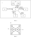
- FIG. 2 is a schematic diagram of a material feeding apparatus according to an embodiment of this application.
- the material feeding apparatus 1 further includes a sensor 13 and a control unit 14.
- the sensor 13 is configured to sense material roll information and send the material roll information to the control unit 14.
- the material roll information may be information related to a status of the material roll 12.
- the material roll information may include surplus material information of the material roll 12, for example, a length of surplus material belt in the material roll 12, and a conveyed length of the material roll 12.
- the material roll information may further include information of material feeding interruption, for example, the transportation of material interrupted at an unwinding position of the material belt 121.
- the sensor 13 may be a distance measuring sensor, a thickness measuring sensor, a photoelectric sensor, or the like, provided that the material roll information can be sensed. This is not limited in the embodiments of this application.
- the control unit 14 is configured to control the rotation status of the rolling shaft 11 based on the material roll information.
- the control unit 14 can control the rolling shaft 11 to start rotating, stop rotating, reduce the rotation speed, or the like based on the material roll information. That is, the control unit 14 can flexibly control a rotation status of the rolling shaft 11 based on the material roll information.
- the material feeding apparatus 1 includes a rolling shaft 11, a sensor 13, and a control unit 14.
- a material roll 12 is disposed on the rolling shaft 11, and the material feeding apparatus 1 is configured to rotate the rolling shaft 11 to convey a material belt 121 in the material roll 12.
- the sensor 13 is configured to sense material roll information and send the material roll information to the control unit 14.
- the control unit 14 is configured to control the rotation status of the rolling shaft 11 based on the material roll information. In this way, the sensor 13 can be used to detect a status of the material roll 12 and sense the material roll information, thereby helping the control unit 14 control the rotation status of the rolling shaft 11 based on the material roll information, for example, control the rolling shaft 11 to decelerate or stop rotating based on the material roll information.
- material roll information can be detected.
- the rotation status of the rolling shaft 11 can be controlled based on the material roll information in a timely manner. Therefore, in the solution of the embodiments of this application, it is unnecessary to manually monitor the status of the material roll in real time, thereby reducing reliance on manual operation and improving the degree of automation.
- the rotation status of the rolling shaft 11 can be controlled in a timely manner when the status of the material roll changes, helping improve production efficiency.
- the senor 13 is disposed at an unwinding position B of the material belt 121, and the sensor 13 is configured to sense first information and send the first information to the control unit 14.
- the first information is used to indicate that the transportation of material is interrupted at the unwinding position B of the material belt 121.
- the control unit 14 is configured to control the rolling shaft 11 to stop rotating based on the first information.
- the first information may be a digital signal. For example, when a value of the digital signal corresponds to a value 1, it indicates that the transportation of material is interrupted at that time. When the value of the digital signal corresponds to a value 0, it indicates that transportation of material is uninterrupted at that time.
- the unwinding position B may be a position at which the material belt 121 starts conveying along a conveying direction A-A of the material belt 121.
- the transportation of material being interrupted means the material belt 121 being broken at the unwinding position B, including a situation in which the material roll has been used up and the surplus material length in the material roll is 0, or a situation in which the material belt 121 is broken at the unwinding position B due to a defect.
- the control unit 14 is configured to control the rolling shaft 11 to stop rotating based on the first information. In this way, when the transportation of material is interrupted, the control unit 14 can control the rolling shaft 11 to stop rotating. Compared to a method in which the rolling shaft decelerates when there is still a certain amount of the surplus material in the material roll 12, the technical solution of this application can reduce deceleration time of rolling shaft 11, which is conducive to improving production efficiency. In addition, compared to a method in which an operator determines whether the transportation of material is interrupted, the technical solution of this application can reduce reliance on manual operation and improve degree of automation. In addition, misjudgment caused by human errors can be avoided, avoiding a situation in which the rolling shaft stops rotating too early or too late, thereby achieving both production efficiency and safety.
- control unit 14 controlling the rolling shaft 11 to stop rotating may mean that the control unit 14 controls the rolling shaft 11 to stop within a preset time.
- the preset time may be specifically set according to an actual rotating speed of the rolling shaft 11 or the like.
- the control unit 14 is an element or a component with a control function.
- the control unit is a programmable logic controller (Programmable Logic Controller, PLC).
- the material feeding apparatus 1 may further include a conveying unit.
- the conveying unit may be configured to convey the material belt 121.
- a speed of the conveying unit conveying the material belt 121 may be the same as a speed of the material roll 12 releasing the material belt 121, that is, the speed of the conveying unit is related to a rotating speed of the rolling shaft 11.
- the speed of the conveying unit is the same as a linear speed of the rolling shaft 11.
- control unit 14 can control the conveying unit to stop or decelerate while controlling the rolling shaft 11 to stop or decelerate.
- the conveying unit includes at least one of a correction mechanism 15, a smoothing apparatus 16, a roller shaft 17, and the like.
- the correction mechanism 15, the smoothing apparatus 16, and the roller shaft 17 are disposed in sequence.
- the correction mechanism 15 and the roller shaft 17 may be configured to convey the material belt 121 along a specified conveying direction, and the smoothing apparatus 16 may be configured to reduce creases on surface of the material belt 121.
- the specific structures of the correction mechanism 15, the smoothing apparatus 16, and the roller shaft 17 are not limited in this application.
- control unit 14 may also control another conveying unit in the material feeding apparatus 1 to stop operating based on the first information, so as to stop conveying the material belt 121.
- the material feeding apparatus 1 of this application may be applied to industrial production fields such as die-cutting and slitting.
- the sensor 13 is disposed at an unwinding position B of the material belt 121, and the sensor 13 is configured to sense first information and send the first information to the control unit 14.
- the first information is used to indicate that the transportation of material is interrupted at the unwinding position B of the material belt 121.
- the control unit 14 is configured to control the rolling shaft 11 to stop rotating based on the first information. In this way, interrupted transportation of material can be detected in a timely manner through the sensor 13, so that when the transportation of material is interrupted, the control unit 14 can control the rolling shaft 11 to stop rotating in a timely manner.
- a situation in which the transportation of material is interrupted can be detected.
- the rolling shaft 11 can be controlled to stop rotating in a timely manner when the transportation of material is interrupted. Therefore, in the solution of this embodiment, it is unnecessary to manually monitor a surplus material length in real time, thereby reducing reliance on manual operation and improving the degree of automation. In addition, the rolling shaft 11 can be controlled to stop rotating in a timely manner when the transportation of material is interrupted, thereby reducing deceleration time of the rolling shaft 11 and improving production efficiency.
- the material feeding apparatus 1 further includes a material clamp 18.
- the material clamp 18 moves away from the rolling shaft 11 relative to the sensor 13 along a conveying direction of the material belt 121.
- the control unit 14 is further configured to control, based on the first information, the material clamp 18 to clamp the material belt 121 tightly to prevent an end of the material belt 121 from sliding out of the material clamp 18.
- the material clamp 18 is a structure that fastens the material belt 121.
- the material clamp 18 is configured to fasten the material belt 121 to prevent the material belt 121 from moving when the rolling shaft 11 stops rotating.
- FIG. 3 is a schematic diagram of a material clamp according to an embodiment of this application.
- the material clamp 18 includes rollers 181 that are opposite each other. While the material belt 121 is clamped tightly by the material clamp 18, the rollers 181 rolls against the material belt 121, thereby securing the material belt 121 and preventing the material belt 121 from moving along the conveying direction.
- control unit 14 controls the rolling shaft 11 to stop rotating based on the first information, and in addition, the control unit 14 synchronously controls the material clamp 18 to clamp the material belt 121 tightly to prevent the end of the material belt 121 from sliding out of the material clamp 18. In this way, the end of the material belt is prevented from sliding out from the material clamp and/or the conveying unit, so that manual re-feeding of material can be avoided, which is conducive to improving production efficiency and quality.
- the material feeding apparatus 1 further includes a surplus material measurement unit 19.
- the surplus material measurement unit 19 is configured to measure length information of surplus material in the material roll 12 and send the length information of surplus material in the material roll 12 to the control unit 14.
- the control unit 14 is further configured to control the rolling shaft 11 to decelerate based on the length information of surplus material before controlling the rolling shaft 11 to stop rotating based on the first information.
- the surplus material measurement unit 19 is a distance measuring instrument.
- the distance measuring instrument is disposed at a fixed position at a given distance from the rolling shaft 11, so that the length of the surplus material in the material roll 12 can be calculated based on the distance between the distance measuring instrument and the material roll 12.
- the length information of surplus material in the material roll 12 may be information related to a length of the surplus material, such as a length of the surplus material and a conveyed length of the material roll.
- the length of the surplus material can be calculated based on the length information of surplus material.
- the surplus material measurement unit 19 can detect the length information of surplus material in the material roll 12, so that the control unit 14 can control the rolling shaft 11 to decelerate based on the length information of surplus material, so as to control the rolling shaft 11 to stop rotating in a timely manner when the transportation of material is interrupted.
- the surplus material measurement unit 19 includes a first surplus material measurement unit 191 and a second surplus material measurement unit 192.
- the first surplus material measurement unit 191 moves away from the rolling shaft 11 relative to the sensor 13 along the conveying direction of the material belt 121, and the first surplus material measurement unit 191 is configured to measure a conveyed length of the material roll 12 and send the conveyed length of the material roll 12 to the control unit 14.
- the conveyed length of the material roll 12 may be a length of the material belt that has been conveyed in the material roll 12, for example, a length of the material belt that has passed through the first surplus material measurement unit 191.
- the first surplus material measurement unit 191 is disposed behind the material clamp 18. That is, in a conveying process of the material belt 121, the material belt first passes through the material clamp 18, and then passes through a position at which the first surplus material measurement unit 191 is located.
- the first surplus material measurement unit 191 is disposed at a position 3 meters behind the material clamp 18.
- the first surplus material measurement unit 191 may be a part of the conveying unit, and the material belt 121 comes into contact with the first surplus material measurement unit 191 in the conveying process. In this way, the first surplus material measurement unit 191 can measure the conveyed length of the material roll 12.
- the second surplus material measurement unit 192 is configured to measure a current distance between the second surplus material measurement unit 192 and the material roll 12, and send the current distance to the control unit 14.
- the decrease in thickness of the material roll 12 is a difference between an initial distance d 1 between the material roll 12 and the second surplus material measurement unit 192 and a current distance d 2 between the material roll 12 and the second surplus material measurement unit 192.
- the distance between the material roll 12 and the second surplus material measurement unit 192 may be a straight-line distance between a first side of the material roll 12 and the second surplus material measurement unit 192.
- the first side of the material roll 12 may be a side of the material roll 12 as a whole that is far from rolling shaft 11 in a radial direction of the material roll 12.
- the second surplus material measurement unit 192 is a distance measuring sensor, and the distance measuring sensor is disposed at a position at a certain distance from the rolling shaft 11.
- the specific position of the second surplus material measurement unit 192 is not specifically limited in this application, provided that the distance between the second surplus material measurement unit 192 and the material roll 12 can be measured.
- the length information of surplus material is obtained by using the first surplus material measurement unit 191 and the second surplus material measurement unit 192 respectively. Compared to obtaining the length information of surplus material in the material roll through only one of the surplus material measurement units, obtaining the length information of surplus material in the material roll through both the first surplus material measurement unit 191 and the second surplus material measurement unit 192 can improve the accuracy of the obtained length information of surplus material.
- control unit 14 is configured to: calculate a first surplus material length based on the conveyed length of the material roll 12; calculate a second surplus material length based on the current distance; control the rolling shaft 11 to decelerate to a first speed in a case that the smaller of the first surplus material length and the second surplus material length has reached a first threshold; and control the rolling shaft 11 to decelerate to a second speed in a case that the larger of the first surplus material length and the second surplus material length has reached the first threshold, where the second speed is less than the first speed.
- An initial total length of the material belt in the material roll 12 is L 0
- d 2 is the current distance between the second surplus material measurement unit 192 and the material roll 12
- d 1 is the initial distance between the second surplus material measurement unit 192 and the material roll 12.
- the first surplus material measurement unit 191 can send the first surplus material length to the control unit 14 after calculating the first surplus material length.
- the second surplus material measurement unit 192 can send the second surplus material length to the control unit 14 after calculating the second surplus material length.
- an error in the first surplus material length is less than 2 meters.
- an error in the second surplus material length is less than 1 meters.
- the first threshold can be set according to an actual situation.
- the first threshold is 5% of the total length of the material roll 12.
- the control unit 14 can obtain the first surplus material length and the second surplus material length at a same moment.
- the first surplus material length and the second surplus material length may vary depending on a difference between the first surplus material measurement unit and the second surplus material measurement unit.
- the control unit 14 controls the rolling shaft to decelerate to the first speed.
- the control unit 14 controls the rolling shaft to decelerate to the second speed. In this way, the rolling shaft 11 can be controlled to decelerate in advance, and the decrease in production efficiency caused by the excessively long deceleration time of the rolling shaft 11 can also be avoided.
- the solution in this embodiment compared to controlling deceleration of the rolling shaft 11 based only on the second surplus material length or the first surplus material length, the solution in this embodiment combines the first surplus material length and the second surplus material length, avoiding the excessively long deceleration time caused by too early deceleration of the rolling shaft 11, as well as avoiding that the rolling shaft 11 cannot stop upon interrupted transportation of material due to too late deceleration of the rolling shaft 11, thereby achieving both production efficiency and safety.
- the first speed is 50% of a predetermined speed of the rolling shaft 11
- the second speed is 25% of the predetermined speed of the rolling shaft 11. This allows for rapid and effective deceleration of the rolling shaft 11, and also facilitates quick stop of the rolling shaft 11 when the transportation of material is interrupted.
- the predetermined speed of the rolling shaft 11 may be a rotating speed of the rolling shaft 11 in a conveying process of the material belt 121.
- the first speed and the second speed may be set according to an actual situation.
- the first speed is 30% of the predetermined speed of the rolling shaft 11
- the second speed is 5% of the predetermined speed of the rolling shaft 11.
- the material feeding apparatus 1 further includes a material replacing unit 10.
- the control unit 14 is configured to control the material replacing unit 10 to replace the material roll 12 based on the first information after controlling the rolling shaft 11 to stop rotating based on the first information.
- the control unit 14 controls the rolling shaft 11 to stop rotating based on the first information
- the control unit 14 controls the material replacing unit 10 to replace the material roll 12 based on the first information. That is, once the transportation of material is interrupted at the unwinding position B, an operation of replacing the material roll is performed.
- the transportation of material being interrupted at the unwinding position B may include a situation in which the material roll is empty and a situation in which the material roll is not empty, but the material belt is broken due to defects. In this way, automated material replacement is implemented after the transportation of material is interrupted, and the degree of automation of the material feeding apparatus 1 is improved. In addition, in this replacing process, an operator is not required to enter the replacing platform to replace material, which is conducive to improving production safety.
- control unit 14 is further configured to control the material replacing unit 10 to replace the material roll 12 based on the first information and the second information after controlling the rolling shaft 11 to stop rotating based on the first information, and the second information is used to indicate that the material roll 12 is an empty material roll 12. This can avoid a situation in which the material roll 12 is replaced before used up.
- the second information may be obtained based on the second surplus material measurement unit 192.
- the material replacing unit 10 includes an automated guided vehicle (Automated Guided Vehicle, AGV).
- the control unit 14 is further configured to, based on the first information, control the automated guided vehicle to take out the rolling shaft 11 and install a new material roll to the rolling shaft 11. In this way, material can be automatically replaced by using the automated guided vehicle, improving the degree of automation.
- AGV Automated Guided Vehicle
- the automated guided vehicle takes out the rolling shaft 11 by using a mechanical claw disposed on the automated guided vehicle and installs a new material roll to the rolling shaft 11.
- the mechanical claw may be provided with a structure such as a cushion to prevent damage to the material roll.
- the material replacing unit 10 includes a cylinder and an automated guided vehicle, where the cylinder is connected to the rolling shaft 11.
- the control unit 14 is further configured to, based on the first information, control the cylinder to push out the rolling shaft 11 and control the automated guided vehicle to install a new material roll to the rolling shaft 11. In this way, an empty rolling shaft 11 is pushed out by the cylinder, and a new material roll is installed by the automated guided vehicle, implementing automation of material replacement.
- the material feeding apparatus 1 may further include a belt connection platform.
- the belt connection platform moves away from the rolling shaft 11 relative to the material clamp 18 along the conveying direction of the material belt 121.
- the control unit 14 controls the material replacing unit 10 to finish material replacement, an operator can connect material belts on the belt connection platform, that is, connect a new material roll to the end of the remaining material belt of the current material roll.
- the senor 13 is a photoelectric sensor. In this way, a situation in which transportation material is interrupted can be detected in a timely manner by detecting changes in light flux received by the photoelectric sensor.
- the sensor 13 can output an action signal by identifying changes in the received light flux, and may be, for example, a light-shielding type photoelectric sensor or a diffusion-emission type photoelectric switch.
- the sensor 13 may be disposed parallel to a thickness direction of the material belt 121 and perpendicular to the conveying direction of the material belt 121.
- the light flux received by the sensor 13 is within a certain range.
- the light flux received by the sensor 13 changes significantly.
- the sensor 13 can generate the first information.
- FIG. 4 is a schematic diagram of a material feeding method according to an embodiment of this application.
- this application provides a material feeding method 200 applied to a material feeding apparatus 1, where the material feeding apparatus 1 includes a rolling shaft 11, a material roll 12 is disposed on the rolling shaft 11, and the material feeding apparatus 1 is configured to rotate the rolling shaft 11 to convey a material belt 121 in the material roll 12.
- the material feeding method 200 includes step 210 and step 220.
- the method in the embodiments of this application may be performed by the control unit 14 of the material feeding apparatus 1.
- Step 210 Obtain material roll information.
- Step 220 Control a rotation status of the rolling shaft 11 based on the material roll information.
- step 210 includes obtaining first information, where the first information is used to indicate that the transportation of material is interrupted at an unwinding position B of the material belt 121.
- Step 220 includes controlling the rolling shaft 11 to stop rotating based on the first information.
- the material feeding apparatus 1 further includes a material clamp 18, where the material clamp 18 moves away from the rolling shaft 11 relative to the sensor 13 along a conveying direction of the material belt 121.
- the method 200 further includes controlling, based on the first information, the material clamp 18 to clamp the material belt 121 tightly to prevent an end of the material belt 121 from sliding out of the material clamp 18.
- the material feeding apparatus 1 further includes a surplus material measurement unit 19, where the surplus material measurement unit 19 is configured to obtain length information of surplus material in the material roll 12.
- the method 200 further includes: obtaining the length information of surplus material in the material roll 12; and controlling the rolling shaft 11 to decelerate based on the length information of surplus material.
- the surplus material measurement unit 19 includes a first surplus material measurement unit 191 and a second surplus material measurement unit 192, where the first surplus material measurement unit 191 moves away from the rolling shaft 11 relative to the sensor 13 along the conveying direction of the material belt 121.
- the first surplus material measurement unit 191 is configured to measure a conveyed length of the material roll 12
- the second surplus material measurement unit 192 is configured to measure a current distance between the second surplus material measurement unit 192 and the material roll 12.
- the obtaining the length information of surplus material in the material roll 12 includes: calculating a first surplus material length based on the conveyed length of the material roll 12; and calculating a second surplus material length based on the current distance.
- the controlling the rolling shaft 11 to decelerate based on the length information of surplus material includes: controlling the rolling shaft 11 to decelerate to a first speed in a case that the larger of the first surplus material length and the second surplus material length has reached the first threshold; and controlling the rolling shaft 11 to decelerate to a second speed in a case that the smaller of the first surplus material length and the second surplus material length has reached the first threshold; where the second speed is less than the first speed.
- the first speed is 50% of a predetermined speed of the rolling shaft 11
- the second speed is 25% of the predetermined speed of the rolling shaft 11.
- the material feeding apparatus 1 further includes a material replacing unit 10. After the controlling the rolling shaft 11 to stop rotating based on the first information, the method 200 further includes controlling the material replacing unit 10 to replace the material roll 12 based on the first information, and the second information is used to indicate that the material roll 12 is an empty material roll 12.
- the material replacing unit 10 includes an automated guided vehicle.
- the controlling the material replacing unit 10 to replace the material roll 12 based on the first information includes, based on the first information, controlling the automated guided vehicle to take out the rolling shaft 11 and installing a new material roll 12 to the rolling shaft 11.
- the material feeding unit 10 includes a cylinder and an automated guided vehicle, where the cylinder is connected to the rolling shaft 11.
- the controlling the material replacing apparatus to replace the material roll 12 based on the first information includes, based on the first information, controlling the cylinder to push out the rolling shaft 11 and control the automated guided vehicle to install a new material roll 12 to the rolling shaft 11.
- the senor 13 is a photoelectric sensor 13.
- FIG. 5 is a flowchart of a material feeding method according to an embodiment of this application. As shown in FIG. 5 , the material feeding method 300 may include the following steps.
- Step 310 Control the rolling shaft 11 to decelerate based on the first surplus material length and the second surplus material length.
- While the rolling shaft 11 is controlled to decelerate based on the first surplus material length and the second surplus material length, other conveying units in the material feeding apparatus can be controlled to decelerate synchronously, thereby implementing full deceleration of the material feeding apparatus.
- Step 320 Based on the first information, simultaneously control the rolling shaft 11 to stop rotating and control the material clamp 18 to clamp the material belt 121 tightly.
- Step 330 Based on the first information, control the material replacing unit 10 to replace material.
- step 320 After step 320, based on the first information, the material replacing unit 10 is controlled to replace material. Therefore, via step 310 to step 330, automatic detection on interruption of transportation of material in the material feeding apparatus and automatic material feeding after the interruption of transportation of material is detected can be implemented.
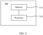
- FIG. 6 is a schematic diagram of a material feeding apparatus according to an embodiment of this application.
- the material feeding apparatus 500 includes a memory 510 and a processor 520.
- the memory 510 is configured to store computer executable instructions.
- the processor 520 is configured to access the memory and execute the computer executable instructions to perform the operations in the material feeding method according to any one of the foregoing embodiments.
- the processor 520 may be an integrated circuit chip and has a signal processing capability.
- the steps of the foregoing method embodiment may be completed by hardware integrated logic circuits in the processor or instructions in the form of software.
- the processor may be a general purpose processor, a digital signal processor (Digital Signal Processor, DSP), an application specific integrated circuit (Application Specific Integrated Circuit, ASIC), a field programmable gate array (Field Programmable Gate Array, FPGA) or another programmable logical device, a discrete gate or transistor logical device, or a discrete hardware component.
- DSP Digital Signal Processor
- ASIC Application Specific Integrated Circuit
- FPGA Field Programmable Gate Array
- the methods and the steps that are disclosed in the embodiments of this application may be implemented or performed.
- the general purpose processor may be a microprocessor, or the processor may be any conventional processor or the like.
- the steps of the methods disclosed with reference to the embodiments of this application may be executed and completed by a hardware encoding processor, or may be executed and completed by using a combination of hardware and software modules in an encoding processor.
- the software module may be located in a storage medium mature in the art such as a random access memory, a flash memory, a read-only memory, a programmable read-only memory, an electrically erasable programmable memory, or a register.
- the storage medium is located in the memory, the processor reads information in the memory, and the steps of the foregoing methods are completed with reference to hardware of the processor
- the memory 510 may be a volatile memory or a non-volatile memory, or may include a volatile memory and a non-volatile memory.
- the non-volatile memory may be a read-only memory (Read-Only Memory, ROM), a programmable read-only memory (Programmable ROM, PROM), an erasable programmable read-only memory (Erasable PROM, EPROM), an electrically erasable programmable read-only memory (Electrically EPROM, EEPROM), or a flash memory.
- the volatile memory may be a random access memory (Random Access Memory, RAM), which is used as an external cache.
- RAMs may be used, for example, a static random access memory (Static RAM, SRAM), a dynamic random access memory (Dynamic RAM, DRAM), a synchronous dynamic random access memory (Synchronous DRAM, SDRAM), a double data rate synchronous dynamic random access memory (Double Data Rate SDRAM, DDRSDRAM), an enhanced synchronous dynamic random access memory (Enhanced SDRAM, ESDRAM), a synchronous link dynamic random access memory (Synchlink DRAM, SLDRAM), and a direct Rambus random access memory (Direct Rambus RAM, DR RAM).
- Static RAM static random access memory
- DRAM dynamic random access memory
- DRAM synchronous dynamic random access memory
- SDRAM double data rate synchronous dynamic random access memory
- Enhanced SDRAM, ESDRAM enhanced synchronous dynamic random access memory
- Synchlink DRAM synchronous link dynamic random access memory
- DR RAM direct Rambus random access memory
- the embodiments of this application provide a storage medium used to store a computer program, where when the computer program is executed by a computing device, the computing device is enabled to implement the method described in any one of the foregoing embodiments.
Landscapes
- Controlling Rewinding, Feeding, Winding, Or Abnormalities Of Webs (AREA)
- Replacement Of Web Rolls (AREA)
- Application Of Or Painting With Fluid Materials (AREA)
Abstract
Description
- This application relates to the field of material feeding technologies, and in particular, to a material feeding apparatus and a material feeding method.
- With the gradual development of automation technologies in the industrial field, the demand for automation of material feeding is also increasing. During actual production, it is difficult to accurately estimate a surplus material length when material feeding is implemented using a material feeding apparatus. Therefore, it is necessary to reduce a material feeding speed when there is still a certain amount of surplus material. In addition, it is necessary to manually monitor the surplus material length and manually stop the material feeding apparatus when the surplus material length approaches zero. This material feeding process relies heavily on manual intervention, which is not conducive to improving the degree of automation. In addition, the excessively long deceleration time is not conducive to improving production efficiency.
- Therefore, how a material feeding apparatus and a material feeding method are provided to improve production efficiency and the degree of automation is a technical problem to be resolved urgently.
- This application provides a material feeding apparatus and a material feeding method, which are conducive to improving production efficiency and the degree of automation.
- According to a first aspect, this application provides a material feeding apparatus, including: a rolling shaft, a sensor, and a control unit, where a material roll is disposed on the rolling shaft, and the material feeding apparatus is configured to rotate the rolling shaft to convey a material belt in the material roll; the sensor is configured to sense material roll information and send the material roll information to the control unit; and the control unit is configured to control a rotation status of the rolling shaft based on the material roll information.
- An embodiment of this application provides a material feeding apparatus, and the material feeding apparatus includes a rolling shaft, a sensor, and a control unit. A material roll is disposed on the rolling shaft, and the material feeding apparatus is configured to rotate the rolling shaft to convey a material belt in the material roll. The sensor is configured to sense material roll information and send the material roll information to the control unit. The control unit is configured to control the rotation status of the rolling shaft based on the material roll information. In this way, the sensor can be used to detect a status of the material roll and sense the material roll information, thereby helping the control unit control the rotation status of the rolling shaft based on the material roll information, for example, control the rolling shaft to decelerate or stop rotating based on the material roll information. Through provision of the sensor, material roll information can be detected. In addition, through provision of the control unit, the rotation status of the rolling shaft can be controlled based on the material roll information in a timely manner. Therefore, in the solution of the embodiments of this application, it is unnecessary to manually monitor the status of the material roll in real time, thereby reducing reliance on manual operation and improving the degree of automation. In addition, the rotation status of the rolling shaft can be controlled in a timely manner when the status of the material roll changes, helping improve production efficiency.
- In a possible implementation, the sensor is disposed at an unwinding position of the material belt, and the sensor is configured to sense first information and send the first information to the control unit, where the first information is used to indicate that the transportation of material is interrupted at the unwinding position of the material belt. The control unit is configured to control the rolling shaft to stop rotating based on the first information.
- In this implementation, the sensor is disposed at an unwinding position of the material belt, and the sensor is configured to sense first information and send the first information to the control unit, where the first information is used to indicate that the transportation of material is interrupted at the unwinding position of the material belt. The control unit is configured to control the rolling shaft to stop rotating based on the first information. In this way, interrupted transportation of material can be detected in a timely manner through the sensor, so that when the transportation of material is interrupted, the control unit can control the rolling shaft to stop rotating in a timely manner. Through provision of the sensor, a situation in which the transportation of material is interrupted can be detected. In addition, through provision of the control unit, the rolling shaft can be controlled to stop rotating in a timely manner when the transportation of material is interrupted. Therefore, in the solution of the embodiments of this application, it is unnecessary to manually monitor a surplus material length in real time, thereby reducing reliance on manual operation and improving the degree of automation. In addition, the rolling shaft can be controlled to stop rotating in a timely manner when the transportation of material is interrupted, thereby reducing deceleration time of the rolling shaft and improving production efficiency.
- In a possible implementation, the material feeding apparatus further includes a material clamp, where the material clamp moves away from the rolling shaft relative to the sensor along a conveying direction of the material belt. The control unit is further configured to control, based on the first information, the material clamp to clamp the material belt tightly to prevent an end of the material belt from sliding out of the material clamp. In this way, when interrupted transportation of material is detected, the material clamp can be controlled to clamp the material belt tightly in a timely manner to prevent the end of the material belt from sliding out of the material clamp, thereby avoiding a situation in which material feeding needs to be restarted manually because the end of the material belt slides out, and further helping improve production efficiency and quality.
- In a possible implementation, the material feeding apparatus further includes a surplus material measurement unit, and the surplus material measurement unit is configured to measure length information of surplus material in the material roll and send the length information of surplus material in the material roll to the control unit. The control unit is further configured to control the rolling shaft to decelerate based on the length information of surplus material before controlling the rolling shaft to stop rotating based on the first information.
- In this implementation, the surplus material measurement unit can detect length information of surplus material in the material roll, so that the control unit can control the rolling shaft to decelerate based on the length information of surplus material, so as to control the rolling shaft to stop rotating in a timely manner when the transportation of material is interrupted.
- In a possible implementation, the surplus material measurement unit includes a first surplus material measurement unit and a second surplus material measurement unit. The first surplus material measurement unit moves away from the rolling shaft relative to the sensor along the conveying direction of the material belt, and the first surplus material measurement unit is configured to measure a conveyed length of the material roll and send the conveyed length of the material roll to the control unit. The second surplus material measurement unit is configured to measure a current distance between the second surplus material measurement unit and the material roll, and send the current distance of the material roll to the control unit.
- In this implementation, the length information of the surplus material is obtained by using the first surplus material measurement unit and the second surplus material measurement unit respectively. Compared to a method in which the length information of surplus material in the material roll is obtained in a single manner, accuracy of the obtained length information of surplus material in the material roll can be improved when the length information of surplus material is obtained by using both the first surplus material measurement unit and the second surplus material measurement unit.
- In a possible implementation, the control unit is further configured to: calculate a first surplus material length based on the conveyed length of the material roll; calculate a second surplus material length based on the current distance; control the rolling shaft to decelerate to a first speed in a case that the smaller of the first surplus material length and the second surplus material length has reached a first threshold; and control the rolling shaft to decelerate to a second speed in a case that the larger of the first surplus material length and the second surplus material length has reached the first threshold, where the second speed is less than the first speed.
- In this implementation, the control unit calculates the first surplus material length based on the conveyed length detected by the first surplus material measurement unit, and calculates the second surplus material length based on the current distance between the material roll and the second surplus material measurement unit detected by the second surplus material measurement unit, so as to determine how to control the rolling shaft to decelerate based on the first surplus material length and the second surplus material length. In this way, compared to a method in which the rolling shaft is controlled to decelerate based only on the second surplus material length, the solution in this implementation can not only avoid the excessively long deceleration time caused by too early deceleration of the rolling shaft, but also avoid that the rolling shaft cannot stop upon interrupted transportation of material due to too late deceleration of the rolling shaft, thereby achieving both production efficiency and safety.
- In a possible implementation, the first speed is 50% of a predetermined speed of the rolling shaft, and the second speed is 25% of the predetermined speed of the rolling shaft. This allows for rapid and effective deceleration of the rolling shaft, and also facilitates quick stopping of the rolling shaft.
- In a possible implementation, the material feeding apparatus further includes a material replacing unit. The control unit is configured to control the material replacing unit to replace the material roll based on the first information after the rolling shaft is controlled to stop rotating based on the first information. In this way, when the transportation of material is interrupted and the material roll is empty, after the rolling shaft stops rotating, the control unit can control the material replacing unit to replace material, thereby implementing automation of the material replacing when the transportation of material is interrupted, and improving the degree of automation of the material feeding apparatus. In addition, in this replacing process, an operator is not required to enter the replacing platform to replace material, which is conducive to improving production safety.
- In a possible implementation, the material replacing unit includes an automated guided vehicle. The control unit is further configured to, based on the first information, control the automated guided vehicle to take out the rolling shaft and install a new material roll to the rolling shaft. In this way, material can be automatically replaced by using the automated guided vehicle, improving the degree of automation.
- In a possible implementation, the material replacing unit includes a cylinder and an automated guided vehicle, where the cylinder is connected to the rolling shaft. The control unit is further configured to, based on the first information, control the cylinder to push out the rolling shaft and control the automated guided vehicle to install a new material roll to the rolling shaft. In this way, an empty rolling shaft is pushed out by the cylinder, and a new material roll is installed by the automated guided vehicle, implementing automation of material replacement.
- In a possible implementation, the sensor is a photoelectric sensor. In this way, a situation in which transportation material is interrupted can be detected in a timely manner by detecting changes in light flux received by the photoelectric sensor.
- According to a second aspect, this application provides a material feeding method applied to a material feeding apparatus. The material feeding apparatus includes a rolling shaft, a material roll is disposed on the rolling shaft, and the material feeding apparatus is configured to rotate the rolling shaft to convey a material belt in the material roll. The material feeding method includes: obtaining material roll information; and controlling a rotation status of the rolling shaft based on the material roll information.
- In a possible implementation, the obtaining material roll information includes obtaining first information, where the first information is used to indicate that the transportation of material is interrupted at an unwinding position of the material belt. The controlling a rotation status of the rolling shaft based on the material roll information includes controlling the rolling shaft to stop rotating based on the first information.
- In a possible implementation, the material feeding apparatus further includes a material clamp, where the material clamp moves away from the rolling shaft relative to the sensor along a conveying direction of the material belt. The method further includes controlling, based on the first information, the material clamp to clamp the material belt tightly to prevent an end of the material belt from sliding out of the material clamp.
- In a possible implementation, the material feeding apparatus further includes a surplus material measurement unit, where the surplus material measurement unit is configured to measure length information of surplus material in the material roll. Before the controlling the rolling shaft to stop rotating based on the first information, the method further includes: obtaining the length information of surplus material in the material roll; and controlling the rolling shaft to decelerate based on the length information of surplus material.
- In a possible implementation, the surplus material measurement unit includes a first surplus material measurement unit and a second surplus material measurement unit, where the first surplus material measurement unit moves away from the rolling shaft relative to the sensor along the conveying direction of the material belt, the first surplus material measurement unit is configured to measure a conveyed length of the material roll, and the second surplus material measurement unit is configured to measure a current distance between the second surplus material measurement unit and the material roll.
- In a possible implementation, the obtaining the length information of surplus material in the material roll includes: calculating a first surplus material length based on the conveyed length of the material roll; and calculating a second surplus material length based on the current distance. The controlling the rolling shaft to decelerate based on the length information of surplus material includes: controlling the rolling shaft to decelerate to a first speed in a case that the smaller of the first surplus material length and the second surplus material length has reached the first threshold; and controlling the rolling shaft to decelerate to a second speed in a case that the larger of the first surplus material length and the second surplus material length has reached the first threshold, where the second speed is less than the first speed.
- In a possible implementation, the first speed is 50% of a predetermined speed of the rolling shaft, and the second speed is 25% of the predetermined speed of the rolling shaft.
- In a possible implementation, the material feeding apparatus further includes a material replacing unit. The control method further includes controlling the material replacing unit to replace the material roll based on the first information after controlling the rolling shaft to stop rotating based on the first information.
- In a possible implementation, the material replacing unit includes an automated guided vehicle. The controlling the material replacing unit to replace the material roll based on the first information includes: based on the first information, controlling the automated guided vehicle to take out the rolling shaft and installing a new material roll to the rolling shaft.
- In a possible implementation, the material feeding unit includes a cylinder and an automated guided vehicle, where the cylinder is connected to the rolling shaft. The controlling the material replacing apparatus to replace the material roll based on the first information and/or the second information includes, based on the first information, controlling the cylinder to push out the rolling shaft and control the automated guided vehicle to install a new material roll to the rolling shaft.
- In a possible implementation, the sensor is a photoelectric sensor.
- According to a third aspect, an embodiment of this application provides a detection apparatus, including a memory configured to store computer executable instructions; and a processor configured to access the memory and execute the computer executable instructions, so as to perform the operations in the method according to any implementation of the second aspect.
- According to a fourth aspect, this application provides a storage medium configured to store a computer program, and when the computer program is executed by a computing device, the computing device performs the method according to any implementation of the second aspect.
- An embodiment of this application provides a material feeding apparatus, and the material feeding apparatus includes a rolling shaft, a sensor, and a control unit. A material roll is disposed on the rolling shaft, and the material feeding apparatus is configured to rotate the rolling shaft to convey a material belt in the material roll. The sensor is configured to sense material roll information and send the material roll information to the control unit. The control unit is configured to control the rotation status of the rolling shaft based on the material roll information. In this way, the sensor can be used to detect a status of the material roll and sense the material roll information, thereby helping the control unit control the rotation status of the rolling shaft based on the material roll information, for example, control the rolling shaft to decelerate or stop rotating based on the material roll information. Through provision of the sensor, material roll information can be detected. In addition, through provision of the control unit, the rotation status of the rolling shaft can be controlled based on the material roll information in a timely manner. Therefore, in the solution of the embodiments of this application, it is unnecessary to manually monitor the status of the material roll in real time, thereby reducing reliance on manual operation and improving the degree of automation. In addition, the rotation status of the rolling shaft can be controlled in a timely manner when the status of the material roll changes, helping improve production efficiency.
- To describe the technical solutions in the embodiments of this application more clearly, the following briefly describes the accompanying drawings required for describing the embodiments of this application. Apparently, the accompanying drawings in the following description show merely some embodiments of this application, and persons of ordinary skill in the art may still derive other drawings from the accompanying drawings without creative efforts.
-
FIG. 1 is a schematic structural diagram of a material feeding apparatus according to an embodiment of this application; -
FIG. 2 is a schematic diagram of a material feeding apparatus according to an embodiment of this application; -
FIG. 3 is a schematic diagram of a material clamp according to an embodiment of this application; -
FIG. 4 is a schematic diagram of a material feeding method according to an embodiment of this application; -
FIG. 5 is a flowchart of a material feeding method according to an embodiment of this application; and -
FIG. 6 is a schematic diagram of a material feeding apparatus according to an embodiment of this application. - The accompanying drawings are not drawn to scale.
- The following further describes the embodiments of this application in detail with reference to the accompanying drawings and implementations. The following detailed description of embodiments and the accompanying drawings are intended to illustrate the principle of this application rather than to limit the scope of this application, meaning this application is not limited to the embodiments as described.
- In the description of this application, it should be noted that, unless otherwise stated, "a plurality of" means at least two; and the orientations or positional relationships indicated by the terms "upper", "lower", "left", "right", "inside", "outside", and the like are merely for ease and brevity of description of this application rather than indicating or implying that the apparatuses or components mentioned must have specific orientations or must be constructed or manipulated according to specific orientations. These terms shall therefore not be construed as limitations on this application. In addition, the terms "first", "second", "third", and the like are merely for the purpose of description and shall not be understood as any indication or implication of relative importance. "Perpendicular" is not perpendicular in the strict sense but within an allowable range of error. "Parallel" is not parallel in the strict sense but within an allowable range of error.
- The orientation terms appearing in the following description all refer to the orientations as shown in the drawings, and do not limit the specific structure of the application. In the description of this application, it should also be noted that unless otherwise specified and defined explicitly, the terms "mount", "connect", and "join" should be understood in their general senses. For example, they may refer to a fixed connection, a detachable connection, or an integral connection, and may refer to a direct connection or an indirect connection via an intermediate medium. Persons of ordinary skill in the art can understand specific meanings of these terms in this application as appropriate to specific situations.
- The term "and/or" in this application is only an associative relationship for describing associated objects, indicating that three relationships may be present. For example, A and/or B may indicate three cases: presence of only A; presence of both A and B; and presence of only B. In addition, the character "/" in this application generally indicates an "or" relationship between contextually associated objects.
- With the gradual development of automation technologies in the industrial field, the demand for automation of material feeding is also increasing. During actual production, it is difficult to accurately estimate a surplus material length when material feeding is implemented using a material feeding apparatus. Therefore, it is necessary to reduce a material feeding speed when there is still a certain amount of surplus material. In addition, it is necessary to manually monitor the surplus material length and manually stop the material feeding apparatus when the surplus material length approaches zero. This material feeding process relies heavily on manual intervention, which is not conducive to improving the degree of automation. In addition, the excessively long deceleration time is not conducive to improving production efficiency.
- In view of this, this application provides a material feeding apparatus, where the material feeding apparatus includes a rolling shaft, a sensor, and a control unit. A material roll is disposed on the rolling shaft, and the material feeding apparatus is configured to rotate the rolling shaft to convey a material belt in the material roll. The sensor is configured to sense material roll information and send the material roll information to the control unit. The control unit is configured to control the rotation status of the rolling shaft based on the material roll information. In this way, the sensor can be used to detect a status of the material roll and sense the material roll information, thereby helping the control unit control the rotation status of the rolling shaft based on the material roll information, for example, control the rolling shaft to decelerate or stop rotating based on the material roll information. Through provision of the sensor, material roll information can be detected. In addition, through provision of the control unit, the rotation status of the rolling shaft can be controlled based on the material roll information in a timely manner. Therefore, in the solution of the embodiments of this application, it is unnecessary to manually monitor the status of the material roll in real time, thereby reducing reliance on manual operation and improving the degree of automation. In addition, the rotation status of the rolling shaft can be controlled in a timely manner when the status of the material roll changes, helping improve production efficiency.
-
FIG. 1 is a schematic diagram depicting a structure of a material feeding apparatus according to an embodiment of this application. As shown inFIG. 1 , thematerial feeding apparatus 1 includes a rollingshaft 11, amaterial roll 12 is disposed on the rollingshaft 11, and thematerial feeding apparatus 1 is configured to rotate the rollingshaft 11 to convey amaterial belt 121 in thematerial roll 12. - The
material roll 12 includes amaterial belt 121, or in other words, thematerial roll 12 is formed by winding thematerial belt 121. In a material feeding process of thematerial feeding apparatus 1, as the rollingshaft 11 rotates, thematerial belt 121 in thematerial roll 12 is conveyed to a destination by thematerial feeding apparatus 1. - The
material feeding apparatus 1 is configured to rotate the rollingshaft 11 to convey thematerial belt 121 in thematerial roll 12, which may include the following cases. For example, thematerial feeding apparatus 1 includes a drive unit, for example, a motor. The motor is connected to the rollingshaft 11 to drive the rollingshaft 11 to rotate. As the rollingshaft 11 rotates, thematerial roll 12 gradually releases thematerial belt 121, so that the material feeding apparatus 1 (for example, a conveying unit of the material feeding apparatus) conveys thematerial belt 121. - The
material roll 12 may be a material that needs to be conveyed in industrial production, for example, thematerial roll 12 is a roll of electrode plate. The specific material and type of thematerial roll 12 are not limited in this application. -
FIG. 2 is a schematic diagram of a material feeding apparatus according to an embodiment of this application. With reference toFIG. 1 andFIG. 2 , thematerial feeding apparatus 1 further includes asensor 13 and acontrol unit 14. - The
sensor 13 is configured to sense material roll information and send the material roll information to thecontrol unit 14. - The material roll information may be information related to a status of the
material roll 12. The material roll information may include surplus material information of thematerial roll 12, for example, a length of surplus material belt in thematerial roll 12, and a conveyed length of thematerial roll 12. The material roll information may further include information of material feeding interruption, for example, the transportation of material interrupted at an unwinding position of thematerial belt 121. - The
sensor 13 may be a distance measuring sensor, a thickness measuring sensor, a photoelectric sensor, or the like, provided that the material roll information can be sensed. This is not limited in the embodiments of this application. - The
control unit 14 is configured to control the rotation status of the rollingshaft 11 based on the material roll information. - The
control unit 14 can control the rollingshaft 11 to start rotating, stop rotating, reduce the rotation speed, or the like based on the material roll information. That is, thecontrol unit 14 can flexibly control a rotation status of the rollingshaft 11 based on the material roll information. - In the embodiments of this application, the
material feeding apparatus 1 includes a rollingshaft 11, asensor 13, and acontrol unit 14. Amaterial roll 12 is disposed on the rollingshaft 11, and thematerial feeding apparatus 1 is configured to rotate the rollingshaft 11 to convey amaterial belt 121 in thematerial roll 12. Thesensor 13 is configured to sense material roll information and send the material roll information to thecontrol unit 14. Thecontrol unit 14 is configured to control the rotation status of the rollingshaft 11 based on the material roll information. In this way, thesensor 13 can be used to detect a status of thematerial roll 12 and sense the material roll information, thereby helping thecontrol unit 14 control the rotation status of the rollingshaft 11 based on the material roll information, for example, control the rollingshaft 11 to decelerate or stop rotating based on the material roll information. Through provision of thesensor 13, material roll information can be detected. In addition, through provision of thecontrol unit 14, the rotation status of the rollingshaft 11 can be controlled based on the material roll information in a timely manner. Therefore, in the solution of the embodiments of this application, it is unnecessary to manually monitor the status of the material roll in real time, thereby reducing reliance on manual operation and improving the degree of automation. In addition, the rotation status of the rollingshaft 11 can be controlled in a timely manner when the status of the material roll changes, helping improve production efficiency. - In an embodiment, the
sensor 13 is disposed at an unwinding position B of thematerial belt 121, and thesensor 13 is configured to sense first information and send the first information to thecontrol unit 14. The first information is used to indicate that the transportation of material is interrupted at the unwinding position B of thematerial belt 121. Thecontrol unit 14 is configured to control the rollingshaft 11 to stop rotating based on the first information. - The first information may be a digital signal. For example, when a value of the digital signal corresponds to a
value 1, it indicates that the transportation of material is interrupted at that time. When the value of the digital signal corresponds to a value 0, it indicates that transportation of material is uninterrupted at that time. - The unwinding position B may be a position at which the
material belt 121 starts conveying along a conveying direction A-A of thematerial belt 121. - The transportation of material being interrupted means the
material belt 121 being broken at the unwinding position B, including a situation in which the material roll has been used up and the surplus material length in the material roll is 0, or a situation in which thematerial belt 121 is broken at the unwinding position B due to a defect. - The
control unit 14 is configured to control the rollingshaft 11 to stop rotating based on the first information. In this way, when the transportation of material is interrupted, thecontrol unit 14 can control the rollingshaft 11 to stop rotating. Compared to a method in which the rolling shaft decelerates when there is still a certain amount of the surplus material in thematerial roll 12, the technical solution of this application can reduce deceleration time of rollingshaft 11, which is conducive to improving production efficiency. In addition, compared to a method in which an operator determines whether the transportation of material is interrupted, the technical solution of this application can reduce reliance on manual operation and improve degree of automation. In addition, misjudgment caused by human errors can be avoided, avoiding a situation in which the rolling shaft stops rotating too early or too late, thereby achieving both production efficiency and safety. - Optionally, the
control unit 14 controlling the rollingshaft 11 to stop rotating may mean that thecontrol unit 14 controls the rollingshaft 11 to stop within a preset time. The preset time may be specifically set according to an actual rotating speed of the rollingshaft 11 or the like. - The
control unit 14 is an element or a component with a control function. For example, the control unit is a programmable logic controller (Programmable Logic Controller, PLC). - Optionally, the
material feeding apparatus 1 may further include a conveying unit. The conveying unit may be configured to convey thematerial belt 121. A speed of the conveying unit conveying thematerial belt 121 may be the same as a speed of thematerial roll 12 releasing thematerial belt 121, that is, the speed of the conveying unit is related to a rotating speed of the rollingshaft 11. For example, the speed of the conveying unit is the same as a linear speed of the rollingshaft 11. - Optionally, the
control unit 14 can control the conveying unit to stop or decelerate while controlling the rollingshaft 11 to stop or decelerate. - Optionally, the conveying unit includes at least one of a
correction mechanism 15, a smoothingapparatus 16, aroller shaft 17, and the like. For example, along the conveying direction A-A of thematerial belt 121, thecorrection mechanism 15, the smoothingapparatus 16, and theroller shaft 17 are disposed in sequence. Thecorrection mechanism 15 and theroller shaft 17 may be configured to convey thematerial belt 121 along a specified conveying direction, and the smoothingapparatus 16 may be configured to reduce creases on surface of thematerial belt 121. The specific structures of thecorrection mechanism 15, the smoothingapparatus 16, and theroller shaft 17 are not limited in this application. - Optionally, the
control unit 14 may also control another conveying unit in thematerial feeding apparatus 1 to stop operating based on the first information, so as to stop conveying thematerial belt 121. - The
material feeding apparatus 1 of this application may be applied to industrial production fields such as die-cutting and slitting. - In this embodiment, the
sensor 13 is disposed at an unwinding position B of thematerial belt 121, and thesensor 13 is configured to sense first information and send the first information to thecontrol unit 14. The first information is used to indicate that the transportation of material is interrupted at the unwinding position B of thematerial belt 121. Thecontrol unit 14 is configured to control the rollingshaft 11 to stop rotating based on the first information. In this way, interrupted transportation of material can be detected in a timely manner through thesensor 13, so that when the transportation of material is interrupted, thecontrol unit 14 can control the rollingshaft 11 to stop rotating in a timely manner. Through provision of thesensor 13, a situation in which the transportation of material is interrupted can be detected. In addition, through provision of thecontrol unit 14, the rollingshaft 11 can be controlled to stop rotating in a timely manner when the transportation of material is interrupted. Therefore, in the solution of this embodiment, it is unnecessary to manually monitor a surplus material length in real time, thereby reducing reliance on manual operation and improving the degree of automation. In addition, the rollingshaft 11 can be controlled to stop rotating in a timely manner when the transportation of material is interrupted, thereby reducing deceleration time of the rollingshaft 11 and improving production efficiency. - In an embodiment, the
material feeding apparatus 1 further includes amaterial clamp 18. Thematerial clamp 18 moves away from the rollingshaft 11 relative to thesensor 13 along a conveying direction of thematerial belt 121. Thecontrol unit 14 is further configured to control, based on the first information, thematerial clamp 18 to clamp thematerial belt 121 tightly to prevent an end of thematerial belt 121 from sliding out of thematerial clamp 18. - The
material clamp 18 is a structure that fastens thematerial belt 121. Thematerial clamp 18 is configured to fasten thematerial belt 121 to prevent thematerial belt 121 from moving when the rollingshaft 11 stops rotating. -
FIG. 3 is a schematic diagram of a material clamp according to an embodiment of this application. As shown inFIG. 3 , thematerial clamp 18 includesrollers 181 that are opposite each other. While thematerial belt 121 is clamped tightly by thematerial clamp 18, therollers 181 rolls against thematerial belt 121, thereby securing thematerial belt 121 and preventing thematerial belt 121 from moving along the conveying direction. - In this embodiment, when the transportation of material is interrupted, the
control unit 14 controls the rollingshaft 11 to stop rotating based on the first information, and in addition, thecontrol unit 14 synchronously controls thematerial clamp 18 to clamp thematerial belt 121 tightly to prevent the end of thematerial belt 121 from sliding out of thematerial clamp 18. In this way, the end of the material belt is prevented from sliding out from the material clamp and/or the conveying unit, so that manual re-feeding of material can be avoided, which is conducive to improving production efficiency and quality. - In an embodiment, the
material feeding apparatus 1 further includes a surplusmaterial measurement unit 19. The surplusmaterial measurement unit 19 is configured to measure length information of surplus material in thematerial roll 12 and send the length information of surplus material in thematerial roll 12 to thecontrol unit 14. Thecontrol unit 14 is further configured to control the rollingshaft 11 to decelerate based on the length information of surplus material before controlling the rollingshaft 11 to stop rotating based on the first information. - Optionally, the surplus
material measurement unit 19 is a distance measuring instrument. The distance measuring instrument is disposed at a fixed position at a given distance from the rollingshaft 11, so that the length of the surplus material in thematerial roll 12 can be calculated based on the distance between the distance measuring instrument and thematerial roll 12. - The length information of surplus material in the
material roll 12 may be information related to a length of the surplus material, such as a length of the surplus material and a conveyed length of the material roll. The length of the surplus material can be calculated based on the length information of surplus material. - In this embodiment, the surplus
material measurement unit 19 can detect the length information of surplus material in thematerial roll 12, so that thecontrol unit 14 can control the rollingshaft 11 to decelerate based on the length information of surplus material, so as to control the rollingshaft 11 to stop rotating in a timely manner when the transportation of material is interrupted. - In an embodiment, the surplus
material measurement unit 19 includes a first surplusmaterial measurement unit 191 and a second surplusmaterial measurement unit 192. - The first surplus
material measurement unit 191 moves away from the rollingshaft 11 relative to thesensor 13 along the conveying direction of thematerial belt 121, and the first surplusmaterial measurement unit 191 is configured to measure a conveyed length of thematerial roll 12 and send the conveyed length of thematerial roll 12 to thecontrol unit 14. - The conveyed length of the
material roll 12 may be a length of the material belt that has been conveyed in thematerial roll 12, for example, a length of the material belt that has passed through the first surplusmaterial measurement unit 191. - Optionally, the first surplus
material measurement unit 191 is disposed behind thematerial clamp 18. That is, in a conveying process of thematerial belt 121, the material belt first passes through thematerial clamp 18, and then passes through a position at which the first surplusmaterial measurement unit 191 is located. For example, the first surplusmaterial measurement unit 191 is disposed at a position 3 meters behind thematerial clamp 18. - Optionally, the first surplus
material measurement unit 191 is a counting encoder, and the conveyed length of thematerial roll 12 is Lp=n*2πR1, where n is a quantity of cycles that a counting encoder wheel rotates, and R1 is the radius of the counting encoder wheel. The first surplusmaterial measurement unit 191 may be a part of the conveying unit, and thematerial belt 121 comes into contact with the first surplusmaterial measurement unit 191 in the conveying process. In this way, the first surplusmaterial measurement unit 191 can measure the conveyed length of thematerial roll 12. - The second surplus
material measurement unit 192 is configured to measure a current distance between the second surplusmaterial measurement unit 192 and thematerial roll 12, and send the current distance to thecontrol unit 14. - As the
material feeding apparatus 1 conveys thematerial belt 121, thickness of thematerial roll 12 gradually decreases, and the distance between thematerial roll 12 and the second surplusmaterial measurement unit 192 gradually increases. The decrease in thickness of thematerial roll 12 is a difference between an initial distance d1 between thematerial roll 12 and the second surplusmaterial measurement unit 192 and a current distance d2 between thematerial roll 12 and the second surplusmaterial measurement unit 192. - The distance between the
material roll 12 and the second surplusmaterial measurement unit 192 may be a straight-line distance between a first side of thematerial roll 12 and the second surplusmaterial measurement unit 192. The first side of thematerial roll 12 may be a side of thematerial roll 12 as a whole that is far from rollingshaft 11 in a radial direction of thematerial roll 12. - Optionally, the second surplus
material measurement unit 192 is a distance measuring sensor, and the distance measuring sensor is disposed at a position at a certain distance from the rollingshaft 11. The specific position of the second surplusmaterial measurement unit 192 is not specifically limited in this application, provided that the distance between the second surplusmaterial measurement unit 192 and thematerial roll 12 can be measured. - In this embodiment, the length information of surplus material is obtained by using the first surplus
material measurement unit 191 and the second surplusmaterial measurement unit 192 respectively. Compared to obtaining the length information of surplus material in the material roll through only one of the surplus material measurement units, obtaining the length information of surplus material in the material roll through both the first surplusmaterial measurement unit 191 and the second surplusmaterial measurement unit 192 can improve the accuracy of the obtained length information of surplus material. - In an embodiment, the
control unit 14 is configured to: calculate a first surplus material length based on the conveyed length of thematerial roll 12; calculate a second surplus material length based on the current distance; control the rollingshaft 11 to decelerate to a first speed in a case that the smaller of the first surplus material length and the second surplus material length has reached a first threshold; and control the rollingshaft 11 to decelerate to a second speed in a case that the larger of the first surplus material length and the second surplus material length has reached the first threshold, where the second speed is less than the first speed. - An initial total length of the material belt in the
material roll 12 is L0, the first surplus material length is L1=L0-Lp, and the second surplus material length is L2=L0-2π(d2-d1). d2 is the current distance between the second surplusmaterial measurement unit 192 and thematerial roll 12, and d1 is the initial distance between the second surplusmaterial measurement unit 192 and thematerial roll 12. - Optionally, the first surplus
material measurement unit 191 can send the first surplus material length to thecontrol unit 14 after calculating the first surplus material length. - Optionally, the second surplus
material measurement unit 192 can send the second surplus material length to thecontrol unit 14 after calculating the second surplus material length. - Optionally, an error in the first surplus material length is less than 2 meters.
- Optionally, an error in the second surplus material length is less than 1 meters.
- The first threshold can be set according to an actual situation. For example, the first threshold is 5% of the total length of the
material roll 12. - In this embodiment, the
control unit 14 can obtain the first surplus material length and the second surplus material length at a same moment. The first surplus material length and the second surplus material length may vary depending on a difference between the first surplus material measurement unit and the second surplus material measurement unit. When any one of the first surplus material length and the second surplus material length has reached the first threshold, such as less than or equal to the first threshold, thecontrol unit 14 controls the rolling shaft to decelerate to the first speed. When the other of the first surplus material length and the second surplus material length has reached the first threshold, thecontrol unit 14 controls the rolling shaft to decelerate to the second speed. In this way, the rollingshaft 11 can be controlled to decelerate in advance, and the decrease in production efficiency caused by the excessively long deceleration time of the rollingshaft 11 can also be avoided. - In this embodiment, compared to controlling deceleration of the rolling
shaft 11 based only on the second surplus material length or the first surplus material length, the solution in this embodiment combines the first surplus material length and the second surplus material length, avoiding the excessively long deceleration time caused by too early deceleration of the rollingshaft 11, as well as avoiding that the rollingshaft 11 cannot stop upon interrupted transportation of material due to too late deceleration of the rollingshaft 11, thereby achieving both production efficiency and safety. - In an embodiment, the first speed is 50% of a predetermined speed of the rolling
shaft 11, and the second speed is 25% of the predetermined speed of the rollingshaft 11. This allows for rapid and effective deceleration of the rollingshaft 11, and also facilitates quick stop of the rollingshaft 11 when the transportation of material is interrupted. - The predetermined speed of the rolling
shaft 11 may be a rotating speed of the rollingshaft 11 in a conveying process of thematerial belt 121. - Optionally, the first speed and the second speed may be set according to an actual situation. For example, the first speed is 30% of the predetermined speed of the rolling
shaft 11, and the second speed is 5% of the predetermined speed of the rollingshaft 11. - In an embodiment, the
material feeding apparatus 1 further includes amaterial replacing unit 10. Thecontrol unit 14 is configured to control thematerial replacing unit 10 to replace thematerial roll 12 based on the first information after controlling the rollingshaft 11 to stop rotating based on the first information. - In this embodiment, after the
control unit 14 controls the rollingshaft 11 to stop rotating based on the first information, thecontrol unit 14 controls thematerial replacing unit 10 to replace thematerial roll 12 based on the first information. That is, once the transportation of material is interrupted at the unwinding position B, an operation of replacing the material roll is performed. The transportation of material being interrupted at the unwinding position B may include a situation in which the material roll is empty and a situation in which the material roll is not empty, but the material belt is broken due to defects. In this way, automated material replacement is implemented after the transportation of material is interrupted, and the degree of automation of thematerial feeding apparatus 1 is improved. In addition, in this replacing process, an operator is not required to enter the replacing platform to replace material, which is conducive to improving production safety. - Optionally, the
control unit 14 is further configured to control thematerial replacing unit 10 to replace thematerial roll 12 based on the first information and the second information after controlling the rollingshaft 11 to stop rotating based on the first information, and the second information is used to indicate that thematerial roll 12 is anempty material roll 12. This can avoid a situation in which thematerial roll 12 is replaced before used up. - Optionally, the second information may be obtained based on the second surplus
material measurement unit 192. - In an embodiment, the
material replacing unit 10 includes an automated guided vehicle (Automated Guided Vehicle, AGV). Thecontrol unit 14 is further configured to, based on the first information, control the automated guided vehicle to take out the rollingshaft 11 and install a new material roll to the rollingshaft 11. In this way, material can be automatically replaced by using the automated guided vehicle, improving the degree of automation. - Optionally, the automated guided vehicle takes out the rolling
shaft 11 by using a mechanical claw disposed on the automated guided vehicle and installs a new material roll to the rollingshaft 11. The mechanical claw may be provided with a structure such as a cushion to prevent damage to the material roll. - In an embodiment, the
material replacing unit 10 includes a cylinder and an automated guided vehicle, where the cylinder is connected to the rollingshaft 11. Thecontrol unit 14 is further configured to, based on the first information, control the cylinder to push out the rollingshaft 11 and control the automated guided vehicle to install a new material roll to the rollingshaft 11. In this way, anempty rolling shaft 11 is pushed out by the cylinder, and a new material roll is installed by the automated guided vehicle, implementing automation of material replacement. - Optionally, the
material feeding apparatus 1 may further include a belt connection platform. The belt connection platform moves away from the rollingshaft 11 relative to thematerial clamp 18 along the conveying direction of thematerial belt 121. After thecontrol unit 14 controls thematerial replacing unit 10 to finish material replacement, an operator can connect material belts on the belt connection platform, that is, connect a new material roll to the end of the remaining material belt of the current material roll. - In an embodiment, the
sensor 13 is a photoelectric sensor. In this way, a situation in which transportation material is interrupted can be detected in a timely manner by detecting changes in light flux received by the photoelectric sensor. - The
sensor 13 can output an action signal by identifying changes in the received light flux, and may be, for example, a light-shielding type photoelectric sensor or a diffusion-emission type photoelectric switch. - The
sensor 13 may be disposed parallel to a thickness direction of thematerial belt 121 and perpendicular to the conveying direction of thematerial belt 121. When transportation of thematerial belt 121 is not interrupted, the light flux received by thesensor 13 is within a certain range. When the transportation of thematerial belt 121 is interrupted, the light flux received by thesensor 13 changes significantly. When the received light flux exceeds the above range, thesensor 13 can generate the first information. - With reference to
FIG. 1 to FIG. 3 , apparatus embodiments of this application are described in detail. The following provides a detailed description of embodiments of the material feeding method of this application. It should be understood that the method embodiments correspond to the apparatus embodiments, and refer to the apparatus embodiments for similar descriptions. -
FIG. 4 is a schematic diagram of a material feeding method according to an embodiment of this application. As shown inFIG. 4 , this application provides amaterial feeding method 200 applied to amaterial feeding apparatus 1, where thematerial feeding apparatus 1 includes a rollingshaft 11, amaterial roll 12 is disposed on the rollingshaft 11, and thematerial feeding apparatus 1 is configured to rotate the rollingshaft 11 to convey amaterial belt 121 in thematerial roll 12. Thematerial feeding method 200 includesstep 210 andstep 220. - The method in the embodiments of this application may be performed by the
control unit 14 of thematerial feeding apparatus 1. - Step 210: Obtain material roll information.
- Step 220: Control a rotation status of the rolling
shaft 11 based on the material roll information. - In an embodiment,
step 210 includes obtaining first information, where the first information is used to indicate that the transportation of material is interrupted at an unwinding position B of thematerial belt 121. Step 220 includes controlling the rollingshaft 11 to stop rotating based on the first information. - In an embodiment, the
material feeding apparatus 1 further includes amaterial clamp 18, where thematerial clamp 18 moves away from the rollingshaft 11 relative to thesensor 13 along a conveying direction of thematerial belt 121. Themethod 200 further includes controlling, based on the first information, thematerial clamp 18 to clamp thematerial belt 121 tightly to prevent an end of thematerial belt 121 from sliding out of thematerial clamp 18. - In an embodiment, the
material feeding apparatus 1 further includes a surplusmaterial measurement unit 19, where the surplusmaterial measurement unit 19 is configured to obtain length information of surplus material in thematerial roll 12. Before the controlling the rollingshaft 11 to stop rotating based on the first information, themethod 200 further includes: obtaining the length information of surplus material in thematerial roll 12; and controlling the rollingshaft 11 to decelerate based on the length information of surplus material. - In an embodiment, the surplus
material measurement unit 19 includes a first surplusmaterial measurement unit 191 and a second surplusmaterial measurement unit 192, where the first surplusmaterial measurement unit 191 moves away from the rollingshaft 11 relative to thesensor 13 along the conveying direction of thematerial belt 121. The first surplusmaterial measurement unit 191 is configured to measure a conveyed length of thematerial roll 12, and the second surplusmaterial measurement unit 192 is configured to measure a current distance between the second surplusmaterial measurement unit 192 and thematerial roll 12. - In an embodiment, the obtaining the length information of surplus material in the
material roll 12 includes: calculating a first surplus material length based on the conveyed length of thematerial roll 12; and calculating a second surplus material length based on the current distance. The controlling the rollingshaft 11 to decelerate based on the length information of surplus material includes: controlling the rollingshaft 11 to decelerate to a first speed in a case that the larger of the first surplus material length and the second surplus material length has reached the first threshold; and controlling the rollingshaft 11 to decelerate to a second speed in a case that the smaller of the first surplus material length and the second surplus material length has reached the first threshold; where the second speed is less than the first speed. - In an embodiment, the first speed is 50% of a predetermined speed of the rolling
shaft 11, and the second speed is 25% of the predetermined speed of the rollingshaft 11. - In an embodiment, the
material feeding apparatus 1 further includes amaterial replacing unit 10. After the controlling the rollingshaft 11 to stop rotating based on the first information, themethod 200 further includes controlling thematerial replacing unit 10 to replace thematerial roll 12 based on the first information, and the second information is used to indicate that thematerial roll 12 is anempty material roll 12. - In an embodiment, the
material replacing unit 10 includes an automated guided vehicle. The controlling thematerial replacing unit 10 to replace thematerial roll 12 based on the first information includes, based on the first information, controlling the automated guided vehicle to take out the rollingshaft 11 and installing anew material roll 12 to the rollingshaft 11. - In an embodiment, the
material feeding unit 10 includes a cylinder and an automated guided vehicle, where the cylinder is connected to the rollingshaft 11. The controlling the material replacing apparatus to replace thematerial roll 12 based on the first information includes, based on the first information, controlling the cylinder to push out the rollingshaft 11 and control the automated guided vehicle to install anew material roll 12 to the rollingshaft 11. - In an embodiment, the
sensor 13 is aphotoelectric sensor 13. -
FIG. 5 is a flowchart of a material feeding method according to an embodiment of this application. As shown inFIG. 5 , thematerial feeding method 300 may include the following steps. - Step 310: Control the rolling
shaft 11 to decelerate based on the first surplus material length and the second surplus material length. - While the rolling
shaft 11 is controlled to decelerate based on the first surplus material length and the second surplus material length, other conveying units in the material feeding apparatus can be controlled to decelerate synchronously, thereby implementing full deceleration of the material feeding apparatus. - Refer to the foregoing content for the specific methods and operations for deceleration based on the first surplus material length and the second surplus material length, and details are not described herein again.
- Step 320: Based on the first information, simultaneously control the rolling
shaft 11 to stop rotating and control thematerial clamp 18 to clamp thematerial belt 121 tightly. - Step 330: Based on the first information, control the
material replacing unit 10 to replace material. - After
step 320, based on the first information, thematerial replacing unit 10 is controlled to replace material. Therefore, viastep 310 to step 330, automatic detection on interruption of transportation of material in the material feeding apparatus and automatic material feeding after the interruption of transportation of material is detected can be implemented. -
FIG. 6 is a schematic diagram of a material feeding apparatus according to an embodiment of this application. As shown inFIG. 6 , in the embodiments of this application, thematerial feeding apparatus 500 includes amemory 510 and aprocessor 520. Thememory 510 is configured to store computer executable instructions. Theprocessor 520 is configured to access the memory and execute the computer executable instructions to perform the operations in the material feeding method according to any one of the foregoing embodiments. - In the embodiments of this application, the
processor 520 may be an integrated circuit chip and has a signal processing capability. During implementation, the steps of the foregoing method embodiment may be completed by hardware integrated logic circuits in the processor or instructions in the form of software. The processor may be a general purpose processor, a digital signal processor (Digital Signal Processor, DSP), an application specific integrated circuit (Application Specific Integrated Circuit, ASIC), a field programmable gate array (Field Programmable Gate Array, FPGA) or another programmable logical device, a discrete gate or transistor logical device, or a discrete hardware component. The methods and the steps that are disclosed in the embodiments of this application may be implemented or performed. The general purpose processor may be a microprocessor, or the processor may be any conventional processor or the like. The steps of the methods disclosed with reference to the embodiments of this application may be executed and completed by a hardware encoding processor, or may be executed and completed by using a combination of hardware and software modules in an encoding processor. The software module may be located in a storage medium mature in the art such as a random access memory, a flash memory, a read-only memory, a programmable read-only memory, an electrically erasable programmable memory, or a register. The storage medium is located in the memory, the processor reads information in the memory, and the steps of the foregoing methods are completed with reference to hardware of the processor - In the embodiments of this application, the
memory 510 may be a volatile memory or a non-volatile memory, or may include a volatile memory and a non-volatile memory. The non-volatile memory may be a read-only memory (Read-Only Memory, ROM), a programmable read-only memory (Programmable ROM, PROM), an erasable programmable read-only memory (Erasable PROM, EPROM), an electrically erasable programmable read-only memory (Electrically EPROM, EEPROM), or a flash memory. The volatile memory may be a random access memory (Random Access Memory, RAM), which is used as an external cache. By way of example but not restrictive description, many forms of RAMs may be used, for example, a static random access memory (Static RAM, SRAM), a dynamic random access memory (Dynamic RAM, DRAM), a synchronous dynamic random access memory (Synchronous DRAM, SDRAM), a double data rate synchronous dynamic random access memory (Double Data Rate SDRAM, DDRSDRAM), an enhanced synchronous dynamic random access memory (Enhanced SDRAM, ESDRAM), a synchronous link dynamic random access memory (Synchlink DRAM, SLDRAM), and a direct Rambus random access memory (Direct Rambus RAM, DR RAM). It should be noted that the memory in the system and method described in this specification is intended to include but not limited to these and any other types of memories. - The embodiments of this application provide a storage medium used to store a computer program, where when the computer program is executed by a computing device, the computing device is enabled to implement the method described in any one of the foregoing embodiments.
- Although this application has been described with reference to the preferred embodiments, various modifications can be made to this application without departing from the scope of this application and the components therein can be replaced with equivalents. In particular, various technical features mentioned in the embodiments can be combined in any manner provided that there is no structural conflict. This application is not limited to the specific embodiments disclosed in this specification, but includes all technical solutions falling within the scope of the claims.
Claims (24)
- A material feeding apparatus, characterized by comprising: a rolling shaft, a sensor, and a control unit, whereina material roll is disposed on the rolling shaft, and the material feeding apparatus is configured to rotate the rolling shaft to convey a material belt in the material roll;the sensor is configured to sense material roll information and send the material roll information to the control unit; andthe control unit is configured to control a rotation status of the rolling shaft based on the material roll information.
- The material feeding apparatus according to claim 1, characterized in that the sensor is disposed at an unwinding position of the material belt, and the sensor is configured to sense first information and send the first information to the control unit, wherein the first information is used to indicate that the transportation of material is interrupted at the unwinding position of the material belt; and
the control unit is configured to control the rolling shaft to stop rotating based on the first information. - The material feeding apparatus according to claim 2, characterized in that the material feeding apparatus further comprises a material clamp, wherein the material clamp moves away from the rolling shaft relative to the sensor along a conveying direction of the material belt; and
the control unit is further configured to:
control, based on the first information, the material clamp to clamp the material belt tightly to prevent an end of the material belt from sliding out of the material clamp. - The material feeding apparatus according to claim 2 or 3, characterized in that the material feeding apparatus further comprises a surplus material measurement unit, wherein the surplus material measurement unit is configured to measure length information of surplus material in the material roll and send the length information of surplus material in the material roll to the control unit; and
the control unit is further configured to:
control the rolling shaft to decelerate based on the length information of surplus material before controlling the rolling shaft to stop rotating based on the first information. - The material feeding apparatus according to claim 4, characterized in that the surplus material measurement unit comprises a first surplus material measurement unit and a second surplus material measurement unit, whereinthe first surplus material measurement unit moves away from the rolling shaft relative to the sensor along the conveying direction of the material belt, and the first surplus material measurement unit is configured to measure a conveyed length of the material roll and send the conveyed length of the material roll to the control unit; andthe second surplus material measurement unit is configured to measure a current distance between the second surplus material measurement unit and the material roll, and send the current distance to the control unit.
- The material feeding apparatus according to claim 5, characterized in that the control unit is further configured to:calculate a first surplus material length based on the conveyed length of the material roll;calculate a second surplus material length based on the current distance;control the rolling shaft to decelerate to a first speed in a case that the smaller of the first surplus material length and the second surplus material length has reached a first threshold; andcontrol the rolling shaft to decelerate to a second speed in a case that the larger of the first surplus material length and the second surplus material length has reached the first threshold, wherein the second speed is less than the first speed.
- The material feeding apparatus according to claim 6, characterized in that the first speed is 50% of a predetermined speed of the rolling shaft, and the second speed is 25% of the predetermined speed of the rolling shaft.
- The material feeding apparatus according to any one of claims 2 to 7, characterized in that the material feeding apparatus further comprises a material replacing unit; and
the control unit is configured to:
control the material replacing unit to replace the material roll based on the first information after controlling the rolling shaft to stop rotating based on the first information. - The material feeding apparatus according to claim 8, characterized in that the material replacing unit comprises an automated guided vehicle; and
the control unit is further configured to:
based on the first information, control the automated guided vehicle to take out the rolling shaft and install a new material roll to the rolling shaft. - The material feeding apparatus according to claim 8, characterized in that the material replacing unit comprises a cylinder and an automated guided vehicle, wherein the cylinder is connected to the rolling shaft; and
the control unit is further configured to:
based on the first information, control the cylinder to push out the rolling shaft and control the automated guided vehicle to install a new material roll to the rolling shaft. - The material feeding apparatus according to any one of claims 1 to 10, characterized in that the sensor is a photoelectric sensor.
- A material feeding method, characterized by being applied to a material feeding apparatus, wherein the material feeding apparatus comprises a rolling shaft, a material roll is disposed on the rolling shaft, and the material feeding apparatus is configured to rotate the rolling shaft to convey a material belt in the material roll; and
the material feeding method comprises:obtaining material roll information; andcontrolling a rotation status of the rolling shaft based on the material roll information. - The material feeding method according to claim 12, characterized in that the obtaining material roll information comprises:obtaining first information, wherein the first information is used to indicate that the transportation of material is interrupted at an unwinding position of the material belt; andthe controlling a rotation status of the rolling shaft based on the material roll information comprises:
controlling the rolling shaft to stop rotating based on the first information. - The material feeding method according to claim 13, characterized in that the material feeding apparatus further comprises a material clamp, wherein the material clamp moves away from the rolling shaft relative to the sensor along a conveying direction of the material belt; and
the method further comprises:
controlling, based on the first information, the material clamp to clamp the material belt tightly to prevent an end of the material belt from sliding out of the material clamp. - The material feeding method according to claim 13 or 14, characterized in that the material feeding apparatus further comprises a surplus material measurement unit, wherein the surplus material measurement unit is configured to measure length information of surplus material in the material roll; and
before the controlling the rolling shaft to stop rotating based on the first information, the method further comprises:obtaining the length information of surplus material in the material roll; andcontrolling the rolling shaft to decelerate based on the length information of surplus material. - The material feeding method according to claim 15, characterized in that the surplus material measurement unit comprises a first surplus material measurement unit and a second surplus material measurement unit, wherein the first surplus material measurement unit moves away from the rolling shaft relative to the sensor along the conveying direction of the material belt, the first surplus material measurement unit is configured to measure a conveyed length of the material roll, and the second surplus material measurement unit is configured to measure a current distance between the second surplus material measurement unit and the material roll.
- The material feeding method according to claim 16, characterized in that the obtaining the length information of surplus material in the material roll comprises:calculating a first surplus material length based on the conveyed length of the material roll; andcalculating a second surplus material length based on the current distance; andthe controlling the rolling shaft to decelerate based on the length information of surplus material comprises:controlling the rolling shaft to decelerate to a first speed in a case that the smaller of the first surplus material length and the second surplus material length has reached a first threshold; andcontrolling the rolling shaft to decelerate to a second speed in a case that the larger of the first surplus material length and the second surplus material length has reached the first threshold, wherein the second speed is less than the first speed.
- The material feeding method according to claim 17, characterized in that the first speed is 50% of a predetermined speed of the rolling shaft, and the second speed is 25% of the predetermined speed of the rolling shaft.
- The material feeding method according to any one of claims 13 to 18, characterized in that the material feeding apparatus further comprises a material replacing unit; and
after the controlling the rolling shaft to stop rotating based on the first information, the method further comprises:
controlling the material replacing unit to replace the material roll based on the first information. - The material feeding method according to claim 19, characterized in that the material replacing unit comprises an automated guided vehicle; and
the controlling the material replacing unit to replace the material roll based on the first information comprises:
based on the first information, controlling the automated guided vehicle to take out the rolling shaft and installing a new material roll to the rolling shaft. - The material feeding method according to claim 19, characterized in that the material feeding unit comprises a cylinder and an automated guided vehicle, wherein the cylinder is connected to the rolling shaft; and
the controlling the material replacing apparatus to replace the material roll based on the first information comprises:
based on the first information, controlling the cylinder to push out the rolling shaft and controlling the automated guided vehicle to install a new material roll to the rolling shaft. - The material feeding method according to any one of claims 12 to 21, characterized in that the sensor is a photoelectric sensor
- A detection apparatus, characterized by comprising:a memory configured to store computer executable instructions; anda processor configured to access the memory and execute the computer executable instructions, so as to perform the operations in the method according to any one of claims 12 to 22.
- A storage medium, characterized in that the storage medium is configured to store a computer program, and when the computer program is executed by a computing device, the computing device is enabled to implement the method according to any one of claims 12 to 22.
Applications Claiming Priority (1)
| Application Number | Priority Date | Filing Date | Title |
|---|---|---|---|
| PCT/CN2022/112962 WO2024036501A1 (en) | 2022-08-17 | 2022-08-17 | Feeding device and feeding method |
Publications (2)
| Publication Number | Publication Date |
|---|---|
| EP4464634A1 true EP4464634A1 (en) | 2024-11-20 |
| EP4464634A4 EP4464634A4 (en) | 2025-03-19 |
Family
ID=89940417
Family Applications (1)
| Application Number | Title | Priority Date | Filing Date |
|---|---|---|---|
| EP22955283.1A Pending EP4464634A4 (en) | 2022-08-17 | 2022-08-17 | Feeding device and feeding method |
Country Status (4)
| Country | Link |
|---|---|
| US (1) | US20240417202A1 (en) |
| EP (1) | EP4464634A4 (en) |
| CN (1) | CN118591504A (en) |
| WO (1) | WO2024036501A1 (en) |
Family Cites Families (18)
| Publication number | Priority date | Publication date | Assignee | Title |
|---|---|---|---|---|
| CA741915A (en) * | 1963-02-18 | 1966-08-30 | Westinghouse Electric Corporation | Strip reeling speed control |
| FR2612503B3 (en) * | 1987-03-19 | 1989-07-28 | Brunet Jean | NEW PULSE DEVICE FOR CONTROLLING THE RUNNING OF TAPES |
| JPH0592216A (en) * | 1991-09-30 | 1993-04-16 | Kawasaki Steel Corp | Coil winding / rewinding device |
| JP3288758B2 (en) * | 1992-07-30 | 2002-06-04 | 株式会社小森コーポレーション | Emergency stop device and method |
| JPH0788550A (en) * | 1993-09-27 | 1995-04-04 | Nippon Steel Corp | Coil processing line entry side automatic deceleration control device |
| EP0930970B1 (en) * | 1996-10-11 | 2001-07-18 | Koenig & Bauer Aktiengesellschaft | Securing device for a printed carrier |
| JP3168169B2 (en) * | 1997-02-17 | 2001-05-21 | 株式会社西村製作所 | Drive motor stop counter for continuous web feeder |
| JP2005022813A (en) * | 2003-07-01 | 2005-01-27 | Goss Graphic Systems Japan Corp | Tension regulating device for running paper in rotary press |
| JP4804579B2 (en) * | 2009-06-30 | 2011-11-02 | キヤノン株式会社 | Recording apparatus and sheet processing method |
| JP5644457B2 (en) * | 2010-12-10 | 2014-12-24 | Jfeスチール株式会社 | Steel strip coil payout control method and payout control device |
| CN104826873B (en) * | 2014-02-12 | 2016-09-14 | 上海梅山钢铁股份有限公司 | Tandem mills starts the control method regardless of rouleau |
| TWI555695B (en) * | 2016-03-28 | 2016-11-01 | 財團法人工業技術研究院 | Roll to roll apparatus |
| CN206021985U (en) * | 2016-08-10 | 2017-03-15 | 新疆八钢金属制品有限公司 | Galvanized strand wires monofilament tension force real-time monitoring device |
| CN207275856U (en) * | 2017-09-28 | 2018-04-27 | 深圳瑞隆新能源科技有限公司 | A kind of coiled strip clout amount monitoring device and system |
| CN209797018U (en) * | 2019-01-24 | 2019-12-17 | 苏州杰锐思自动化设备有限公司 | Synchronous buffer memory system in pole piece material area of adaptation in laser film-making coiling all-in-one |
| CN110271886A (en) * | 2019-07-17 | 2019-09-24 | 广州保瑞医疗技术有限公司 | Machine for forming filter element and feeding structure |
| CN114314129B (en) * | 2022-02-08 | 2024-04-23 | 庸博(厦门)电气技术有限公司 | Tension control method, device and equipment of cloth rolling system |
| CN114604668A (en) * | 2022-03-16 | 2022-06-10 | 杭州海潮橡胶有限公司 | Tire building machine crown band strip unwinding tension control device, method, device and program product |
-
2022
- 2022-08-17 EP EP22955283.1A patent/EP4464634A4/en active Pending
- 2022-08-17 WO PCT/CN2022/112962 patent/WO2024036501A1/en not_active Ceased
- 2022-08-17 CN CN202280090569.4A patent/CN118591504A/en active Pending
-
2024
- 2024-08-27 US US18/816,951 patent/US20240417202A1/en active Pending
Also Published As
| Publication number | Publication date |
|---|---|
| US20240417202A1 (en) | 2024-12-19 |
| WO2024036501A1 (en) | 2024-02-22 |
| CN118591504A (en) | 2024-09-03 |
| EP4464634A4 (en) | 2025-03-19 |
Similar Documents
| Publication | Publication Date | Title |
|---|---|---|
| US7156340B2 (en) | Strip continuous supply apparatus and method | |
| US4949607A (en) | Control system for web material cutting line | |
| US6602367B2 (en) | Method for winding strips on the tire building machine | |
| CN105531214A (en) | Apparatus and method for tracking defects in sheet materials | |
| CN115709145B (en) | A composite control system and method for unifying width reference and automatically aligning the data. | |
| EP1044915B1 (en) | Web cutting apparatus and method | |
| US6603887B1 (en) | Process and apparatus for detecting printed marks | |
| US20240417202A1 (en) | Material feeding apparatus and material feeding method | |
| CN117699545A (en) | Automatic coil changing closed loop deviation rectifying control system | |
| US7654758B2 (en) | Systems and methods for determining media size | |
| JPH0238958A (en) | Stop controller for web conveyance line | |
| JP2016098046A (en) | Remaining amount measuring device, control device, web conveying device, remaining amount measuring method, and control method | |
| CN218574092U (en) | Transfer type coating equipment | |
| KR100920578B1 (en) | Coil thickness measuring device | |
| CN118974513A (en) | Surface shape measuring device, surface shape measuring method, and belt management method | |
| CN116493660A (en) | Slitting system and slitting method | |
| JPH11254034A (en) | Rolled material tail end detection method and device | |
| KR20020052003A (en) | Method for controlling thickness of tandem cold mill | |
| JPH05180624A (en) | Sheet-size measuring apparatus having variable belt conveyer | |
| JPH09216117A (en) | Steel plate automatic aligning method | |
| EP4563508A1 (en) | A method for monitoring a web handling arrangement | |
| JPH0755560Y2 (en) | Automatic document feeder for copiers | |
| CN223704668U (en) | Deviation rectifying assembly | |
| JP2606483B2 (en) | Sheet size measuring device | |
| KR20140102060A (en) | Size Measuring Instrumant for Remmants Metal Materials |
Legal Events
| Date | Code | Title | Description |
|---|---|---|---|
| STAA | Information on the status of an ep patent application or granted ep patent |
Free format text: STATUS: THE INTERNATIONAL PUBLICATION HAS BEEN MADE |
|
| PUAI | Public reference made under article 153(3) epc to a published international application that has entered the european phase |
Free format text: ORIGINAL CODE: 0009012 |
|
| STAA | Information on the status of an ep patent application or granted ep patent |
Free format text: STATUS: REQUEST FOR EXAMINATION WAS MADE |
|
| 17P | Request for examination filed |
Effective date: 20240816 |
|
| AK | Designated contracting states |
Kind code of ref document: A1 Designated state(s): AL AT BE BG CH CY CZ DE DK EE ES FI FR GB GR HR HU IE IS IT LI LT LU LV MC MK MT NL NO PL PT RO RS SE SI SK SM TR |
|
| REG | Reference to a national code |
Ref country code: DE Ref legal event code: R079 Free format text: PREVIOUS MAIN CLASS: B65H0026060000 Ipc: B65H0026020000 |
|
| RAP1 | Party data changed (applicant data changed or rights of an application transferred) |
Owner name: CONTEMPORARY AMPEREX TECHNOLOGY(HONG KONG) LIMITED |
|
| A4 | Supplementary search report drawn up and despatched |
Effective date: 20250218 |
|
| RIC1 | Information provided on ipc code assigned before grant |
Ipc: B65H 19/12 20060101ALI20250212BHEP Ipc: B65H 26/06 20060101ALI20250212BHEP Ipc: B65H 26/02 20060101AFI20250212BHEP |
|
| STAA | Information on the status of an ep patent application or granted ep patent |
Free format text: STATUS: EXAMINATION IS IN PROGRESS |
|
| 17Q | First examination report despatched |
Effective date: 20250912 |
|
| DAV | Request for validation of the european patent (deleted) | ||
| DAX | Request for extension of the european patent (deleted) | ||
| GRAP | Despatch of communication of intention to grant a patent |
Free format text: ORIGINAL CODE: EPIDOSNIGR1 |
|
| STAA | Information on the status of an ep patent application or granted ep patent |
Free format text: STATUS: GRANT OF PATENT IS INTENDED |
|
| INTG | Intention to grant announced |
Effective date: 20260506 |
|
| GRAS | Grant fee paid |
Free format text: ORIGINAL CODE: EPIDOSNIGR3 |