EP4464457B1 - Lateral processing machine - Google Patents
Lateral processing machine Download PDFInfo
- Publication number
- EP4464457B1 EP4464457B1 EP24161559.0A EP24161559A EP4464457B1 EP 4464457 B1 EP4464457 B1 EP 4464457B1 EP 24161559 A EP24161559 A EP 24161559A EP 4464457 B1 EP4464457 B1 EP 4464457B1
- Authority
- EP
- European Patent Office
- Prior art keywords
- box
- disposed
- cover
- processing unit
- spindle
- Prior art date
- Legal status (The legal status is an assumption and is not a legal conclusion. Google has not performed a legal analysis and makes no representation as to the accuracy of the status listed.)
- Active
Links
Images




Classifications
-
- B—PERFORMING OPERATIONS; TRANSPORTING
- B23—MACHINE TOOLS; METAL-WORKING NOT OTHERWISE PROVIDED FOR
- B23Q—DETAILS, COMPONENTS, OR ACCESSORIES FOR MACHINE TOOLS, e.g. ARRANGEMENTS FOR COPYING OR CONTROLLING; MACHINE TOOLS IN GENERAL CHARACTERISED BY THE CONSTRUCTION OF PARTICULAR DETAILS OR COMPONENTS; COMBINATIONS OR ASSOCIATIONS OF METAL-WORKING MACHINES, NOT DIRECTED TO A PARTICULAR RESULT
- B23Q3/00—Devices holding, supporting, or positioning work or tools, of a kind normally removable from the machine
- B23Q3/155—Arrangements for automatic insertion or removal of tools, e.g. combined with manual handling
-
- B—PERFORMING OPERATIONS; TRANSPORTING
- B23—MACHINE TOOLS; METAL-WORKING NOT OTHERWISE PROVIDED FOR
- B23Q—DETAILS, COMPONENTS, OR ACCESSORIES FOR MACHINE TOOLS, e.g. ARRANGEMENTS FOR COPYING OR CONTROLLING; MACHINE TOOLS IN GENERAL CHARACTERISED BY THE CONSTRUCTION OF PARTICULAR DETAILS OR COMPONENTS; COMBINATIONS OR ASSOCIATIONS OF METAL-WORKING MACHINES, NOT DIRECTED TO A PARTICULAR RESULT
- B23Q11/00—Accessories fitted to machine tools for keeping tools or parts of the machine in good working condition or for cooling work; Safety devices specially combined with or arranged in, or specially adapted for use in connection with, machine tools
- B23Q11/08—Protective coverings for parts of machine tools; Splash guards
- B23Q11/0825—Relatively slidable coverings, e.g. telescopic
-
- B—PERFORMING OPERATIONS; TRANSPORTING
- B23—MACHINE TOOLS; METAL-WORKING NOT OTHERWISE PROVIDED FOR
- B23Q—DETAILS, COMPONENTS, OR ACCESSORIES FOR MACHINE TOOLS, e.g. ARRANGEMENTS FOR COPYING OR CONTROLLING; MACHINE TOOLS IN GENERAL CHARACTERISED BY THE CONSTRUCTION OF PARTICULAR DETAILS OR COMPONENTS; COMBINATIONS OR ASSOCIATIONS OF METAL-WORKING MACHINES, NOT DIRECTED TO A PARTICULAR RESULT
- B23Q1/00—Members which are comprised in the general build-up of a form of machine, particularly relatively large fixed members
- B23Q1/25—Movable or adjustable work or tool supports
-
- B—PERFORMING OPERATIONS; TRANSPORTING
- B23—MACHINE TOOLS; METAL-WORKING NOT OTHERWISE PROVIDED FOR
- B23Q—DETAILS, COMPONENTS, OR ACCESSORIES FOR MACHINE TOOLS, e.g. ARRANGEMENTS FOR COPYING OR CONTROLLING; MACHINE TOOLS IN GENERAL CHARACTERISED BY THE CONSTRUCTION OF PARTICULAR DETAILS OR COMPONENTS; COMBINATIONS OR ASSOCIATIONS OF METAL-WORKING MACHINES, NOT DIRECTED TO A PARTICULAR RESULT
- B23Q1/00—Members which are comprised in the general build-up of a form of machine, particularly relatively large fixed members
- B23Q1/25—Movable or adjustable work or tool supports
- B23Q1/44—Movable or adjustable work or tool supports using particular mechanisms
- B23Q1/56—Movable or adjustable work or tool supports using particular mechanisms with sliding pairs only, the sliding pairs being the first two elements of the mechanism
-
- B—PERFORMING OPERATIONS; TRANSPORTING
- B23—MACHINE TOOLS; METAL-WORKING NOT OTHERWISE PROVIDED FOR
- B23Q—DETAILS, COMPONENTS, OR ACCESSORIES FOR MACHINE TOOLS, e.g. ARRANGEMENTS FOR COPYING OR CONTROLLING; MACHINE TOOLS IN GENERAL CHARACTERISED BY THE CONSTRUCTION OF PARTICULAR DETAILS OR COMPONENTS; COMBINATIONS OR ASSOCIATIONS OF METAL-WORKING MACHINES, NOT DIRECTED TO A PARTICULAR RESULT
- B23Q1/00—Members which are comprised in the general build-up of a form of machine, particularly relatively large fixed members
- B23Q1/01—Frames, beds, pillars or like members; Arrangement of ways
- B23Q1/015—Frames, beds, pillars
-
- B—PERFORMING OPERATIONS; TRANSPORTING
- B23—MACHINE TOOLS; METAL-WORKING NOT OTHERWISE PROVIDED FOR
- B23Q—DETAILS, COMPONENTS, OR ACCESSORIES FOR MACHINE TOOLS, e.g. ARRANGEMENTS FOR COPYING OR CONTROLLING; MACHINE TOOLS IN GENERAL CHARACTERISED BY THE CONSTRUCTION OF PARTICULAR DETAILS OR COMPONENTS; COMBINATIONS OR ASSOCIATIONS OF METAL-WORKING MACHINES, NOT DIRECTED TO A PARTICULAR RESULT
- B23Q1/00—Members which are comprised in the general build-up of a form of machine, particularly relatively large fixed members
- B23Q1/25—Movable or adjustable work or tool supports
- B23Q1/44—Movable or adjustable work or tool supports using particular mechanisms
- B23Q1/56—Movable or adjustable work or tool supports using particular mechanisms with sliding pairs only, the sliding pairs being the first two elements of the mechanism
- B23Q1/60—Movable or adjustable work or tool supports using particular mechanisms with sliding pairs only, the sliding pairs being the first two elements of the mechanism two sliding pairs only, the sliding pairs being the first two elements of the mechanism
- B23Q1/62—Movable or adjustable work or tool supports using particular mechanisms with sliding pairs only, the sliding pairs being the first two elements of the mechanism two sliding pairs only, the sliding pairs being the first two elements of the mechanism with perpendicular axes, e.g. cross-slides
- B23Q1/621—Movable or adjustable work or tool supports using particular mechanisms with sliding pairs only, the sliding pairs being the first two elements of the mechanism two sliding pairs only, the sliding pairs being the first two elements of the mechanism with perpendicular axes, e.g. cross-slides a single sliding pair followed perpendicularly by a single sliding pair
- B23Q1/626—Movable or adjustable work or tool supports using particular mechanisms with sliding pairs only, the sliding pairs being the first two elements of the mechanism two sliding pairs only, the sliding pairs being the first two elements of the mechanism with perpendicular axes, e.g. cross-slides a single sliding pair followed perpendicularly by a single sliding pair followed perpendicularly by a single sliding pair
-
- B—PERFORMING OPERATIONS; TRANSPORTING
- B23—MACHINE TOOLS; METAL-WORKING NOT OTHERWISE PROVIDED FOR
- B23Q—DETAILS, COMPONENTS, OR ACCESSORIES FOR MACHINE TOOLS, e.g. ARRANGEMENTS FOR COPYING OR CONTROLLING; MACHINE TOOLS IN GENERAL CHARACTERISED BY THE CONSTRUCTION OF PARTICULAR DETAILS OR COMPONENTS; COMBINATIONS OR ASSOCIATIONS OF METAL-WORKING MACHINES, NOT DIRECTED TO A PARTICULAR RESULT
- B23Q39/00—Metal-working machines incorporating a plurality of sub-assemblies, each capable of performing a metal-working operation
- B23Q39/02—Metal-working machines incorporating a plurality of sub-assemblies, each capable of performing a metal-working operation the sub-assemblies being capable of being brought to act at a single operating station
-
- B—PERFORMING OPERATIONS; TRANSPORTING
- B23—MACHINE TOOLS; METAL-WORKING NOT OTHERWISE PROVIDED FOR
- B23Q—DETAILS, COMPONENTS, OR ACCESSORIES FOR MACHINE TOOLS, e.g. ARRANGEMENTS FOR COPYING OR CONTROLLING; MACHINE TOOLS IN GENERAL CHARACTERISED BY THE CONSTRUCTION OF PARTICULAR DETAILS OR COMPONENTS; COMBINATIONS OR ASSOCIATIONS OF METAL-WORKING MACHINES, NOT DIRECTED TO A PARTICULAR RESULT
- B23Q39/00—Metal-working machines incorporating a plurality of sub-assemblies, each capable of performing a metal-working operation
- B23Q39/04—Metal-working machines incorporating a plurality of sub-assemblies, each capable of performing a metal-working operation the sub-assemblies being arranged to operate simultaneously at different stations, e.g. with an annular work-table moved in steps
-
- B—PERFORMING OPERATIONS; TRANSPORTING
- B23—MACHINE TOOLS; METAL-WORKING NOT OTHERWISE PROVIDED FOR
- B23Q—DETAILS, COMPONENTS, OR ACCESSORIES FOR MACHINE TOOLS, e.g. ARRANGEMENTS FOR COPYING OR CONTROLLING; MACHINE TOOLS IN GENERAL CHARACTERISED BY THE CONSTRUCTION OF PARTICULAR DETAILS OR COMPONENTS; COMBINATIONS OR ASSOCIATIONS OF METAL-WORKING MACHINES, NOT DIRECTED TO A PARTICULAR RESULT
- B23Q5/00—Driving or feeding mechanisms; Control arrangements therefor
- B23Q5/22—Feeding members carrying tools or work
- B23Q5/32—Feeding working-spindles
- B23Q5/326—Feeding working-spindles screw-operated
Definitions
- the present invention relates to a lateral processing machine.
- a conventional lateral machine tool includes an X-axis guide rail disposed on an upper surface of a bed, a column mounted on the X-axis guide rail and movable in X direction, a Y-axis guide rail disposed on one side surface of the column, a saddle supported by the Y-axis guide rail and movable in Y direction, a Z-axis guide rail disposed on the saddle, and a spindle head supported in a horizontal posture by the Z-axis guide rail ( Japanese Patent No. 4514310 ).
- CN 109 262 371 A discloses a horizontal type machining center.
- the horizontal type machining center comprises a base, above the front end of the base is provided with a Z-axis guide rail, and above the rear end of the base is provided with is provided with a separating frame and stand columns behind the separating frame; above the Z-axis guide rail an index plate body is slidingly mounted; an switchboard support base is mounted above the base and in front of the index plate body; a first index table is mounted above the switchboard support base; a second index table is mounted above the first index table; a switchboard rotating base is connected between the first index table and the second index table.
- the horizontal type machining center comprises the two index tables, when one of the index tables is applied to machining parts, the other index table can change replace machined parts with blank parts, so that high working efficiency can be achieved.
- JP S62 218 008 A for the movement to each of X, Y, Z axial directions, respective drive means are provided so as to control the movement of a plurality of spindles - equipped with work tools - separately.
- each of the spindles is moved from their original positions to the X and Y axial directions for making them cover each one quarter of one surface area of the work. Subsequently, the spindle is moved to the Z axial direction for drilling a hole.
- An object of the present invention is to provide a multi-axis lateral processing machine capable of separating a drive unit from a processing region.
- a first aspect of the present invention provides a lateral processing machine, including:
- a second aspect of the present invention provides a lateral processing machine, including:
- a third aspect of the present invention provides a tool changer for exchanging a tool with a spindle positioned at tool changing position, the tool changer including:
- the first Y box may include a first box hole through which the first ram extends.
- the first processing unit may include a first body.
- the first body may extend through the first box hole.
- the first Y box may include a first packing that seals a gap between the first body and the first box hole.
- the second Y box may include a second box hole through which the second ram extends.
- the second processing unit may include a second body.
- the second body may extend through the second box hole.
- the second Y box may include a second packing that seals a gap between the second body and the second box hole.
- the third Y box may include a third box hole through which the third ram extends.
- the third processing unit may include a third body.
- the third body may extend through the third box hole.
- the third Y box may include a third packing that seals a gap between the third body and the third box hole.
- the fourth Y box may include a fourth box hole through which the fourth ram extends.
- the fourth processing unit may include a fourth body.
- the fourth body may extend through the fourth box hole.
- the fourth Y box may include a fourth packing that seals a gap between the fourth body and the fourth box hole.
- the expansion cover is, for example, a bellows, a roll cover, or a telescopic cover.
- the lateral processing machine may include a second lower X-axis driving device that is disposed on the bed and drives a lower end portion of the second moving column in X direction, and a second upper X-axis driving device that is disposed above the bed and drives an upper end portion of the second moving column in X direction in synchronization with the second lower X-axis driving device.
- the first upper X-axis driving device may be disposed on the fixed beam.
- the second upper X-axis driving device may be disposed on the fixed beam.
- the second lower X-axis driving device may include a lower X helical rack, a second lower X helical gear that meshes with the lower X helical rack, and a second lower X motor connected to the second lower X helical gear and disposed on a lower end portion of the second moving column.
- the second upper X-axis driving device may include an upper X helical rack, a second upper X helical gear that meshes with the upper X helical rack, and a second upper X motor connected to the second upper X helical gear and disposed on an upper end portion of the second moving column.
- the lateral processing machine may include a first Y-axis driving device disposed on the first moving column.
- the first Y-axis driving device may include a first Y helical rack disposed on the first moving column, a first Y helical gear that meshes with the first Y helical rack, and a first Y motor connected to the first Y helical gear and disposed in the first processing unit.
- the first Y-axis driving device may be disposed on a first X side of the first moving column.
- the first Y helical rack may be disposed on the first X side of the first moving column.
- the lateral processing machine may include a second Y-axis driving device disposed on the first moving column.
- the second Y-axis driving device may include the first Y helical rack, a second Y helical gear that meshes with the first Y helical rack, and a second Y motor connected to the second Y helical gear and disposed in the second processing unit.
- the second Y-axis driving device may be disposed on a first X side of the first moving column.
- the lateral processing machine may include a third Y-axis driving device disposed on the second moving column.
- the third Y-axis driving device may include a second Y helical rack disposed on the second moving column, a third Y helical gear that meshes with the second Y helical rack, and a third Y motor connected to the third Y helical gear and disposed in the third processing unit.
- the third Y-axis driving device may be disposed on a second X side of the second moving column.
- the second Y helical rack may be disposed on a second X side of the second moving column.
- the lateral processing machine may include a fourth Y-axis driving device disposed on the second moving column.
- the fourth Y-axis driving device may include the second Y helical rack, a fourth Y helical gear that meshes with the second Y helical rack, and a fourth Y motor connected to the fourth Y helical gear and disposed in the fourth Y processing unit.
- the fourth Y-axis driving device may be disposed on a second X side of the second moving column.
- the lateral processing machine may include a first Y base and a second Y base that are guided by the first Y-axis guide to move in Y direction.
- the first processing unit may be removably disposed on the first Y base.
- the lateral processing machine may include a first fastening member for fastening the first processing unit to the first Y base.
- the second processing unit may be removably disposed on the second Y base.
- the lateral processing machine may include a second fastening member for fastening the second processing unit to the second Y base.
- the lateral machine may include a third Y base and a fourth Y base that are guided by the second Y-axis guide to move in Y direction.
- the third processing unit may be removably disposed on the third Y base.
- the lateral processing machine may include a third fastening member for fastening the third processing unit to the third Y base.
- the fourth processing unit may be removably disposed on the fourth Y base.
- the lateral processing machine may include a fourth fastening member for fastening the fourth processing unit to the fourth Y base.
- the ram can be replaced with a spindle head.
- the body can be replaced with a Z base.
- the first spindle may have a first spindle hole.
- the first spindle may include a first tool unclamping device.
- the second spindle may have a second spindle hole.
- the second spindle may include a second tool unclamping device.
- the third spindle may have a third spindle hole.
- the third spindle may include a third tool unclamping device.
- the fourth spindle may have a fourth spindle hole.
- the fourth spindle may include a fourth tool unclamping device.
- the first spindle is configured to move toward a second X direction to reach a first tool changing position.
- the second spindle is configured to move toward the second X direction to reach a second tool changing position.
- the second spindle is configured to reach the second tool changing position at the same time that the first spindle reaches the first tool changing position.
- the third spindle is configured to move toward a first X direction to reach a third tool changing position.
- the fourth spindle is configured to move toward a first X direction to reach a fourth tool changing position.
- the fourth spindle is configured to reach the fourth tool changing position at the same time that the third spindle reaches the third tool changing position.
- the first spindle may be configured not to interfere with the first tool changer when positioned at the first tool changing position.
- the first shutter of the first tool changer may be configured not to interfere with the first spindle located at the first tool changing position when the first shutter is at the processing position.
- the second spindle may be configured not to interfere with the second tool changer when positioned at the second tool changing position.
- the second shutter of the second tool changer may be configured not to interfere with the second spindle located at the second tool changing position when the second shutter is at the processing position.
- the third spindle may be configured not to interfere with the third tool changer when positioned at the third tool changing position.
- the third shutter of the third tool changer may be configured not to interfere with the third spindle located at the third tool changing position when the third shutter is at the processing position.
- the fourth spindle may be configured not to interfere with the fourth tool changer when positioned at the fourth tool changing position.
- the fourth shutter of the fourth tool changer may be configured not to interfere with the fourth spindle located at the fourth tool changing position when the fourth shutter is at the processing position.
- the lateral processing machine may include,
- the lateral processing machine may include,
- the first lower X-axis driving device may include,
- the first upper X-axis driving device may include,
- a multi-axial lateral processing machine capable of separating a drive unit from a processing region.
- a lateral processing machine 10 includes a bed 11, a pair of floor surface X-axis guides 13, a pair of fixed support columns 15, a fixed beam 17, an upper X-axis guide 19, a first processing unit group 20, a second processing unit group 22, a bellows cover (expansion cover) 40, a first ATC (first automatic tool changer) 511, a second ATC (second automatic tool changer) 512, a third ATC (third automatic tool changer) 513, and a fourth ATC (fourth automatic tool changer) 514.
- first ATC first automatic tool changer
- second ATC second automatic tool changer
- third ATC third automatic tool changer
- fourth ATC fourth automatic tool changer
- the left-right direction is defined as an X direction (the left as viewed from the front is defined as +X direction), the vertical direction is defined as a Y direction (the upward is defined as +Y direction), and the front-rear direction is defined as a Z direction (the back as viewed from the front is defined as +Z direction).
- the floor surface X-axis guide 13 includes a lower X guide rail 13a and a lower X guide block 13b.
- the floor surface X-axis guide 13 extends in X direction.
- the lower X guide rail 13a which extends in X direction, is fixed to the upper surface of the bed 11.
- the lower X guide block 13b which is disposed on the lower X guide rail 13a, moves in X direction.
- the pair of fixed support columns 15 are disposed at both end portions of the bed 11 in X direction.
- the fixed support column 15 includes a main column 15a and a sub-column 15b.
- the fixed support column 15 has a closed shape when viewed from Y direction.
- the sub-column 15b is disposed frontward (-Z direction) from the main column 15a.
- the fixed beam 17 is bridged between the upper end portions of the pair of fixed support columns 15.
- the fixed beam 17 extends in X direction.
- the upper X-axis guide 19 includes an upper X guide rail 19a and an upper X guide block 19b.
- the upper X guide rail 19a which extends in X direction, is fixed to the rear surface of the fixed beam 17.
- the upper X guide block 19b which is disposed on the upper X guide rail 19a, moves in X direction.
- the first processing unit group 20 includes a first moving column 211, a first lower X-axis driving device 231, a first upper X-axis driving device 251, a first Y-axis guide 271, a first Y base 301, a first processing unit 291, a first Y-axis driving device 331, a second Y base 302, a second processing unit 292, and a second Y-axis driving device 332.
- the first moving column 211 includes a base portion 211a and a column portion 211b.
- the base portion 211a is fastened to the lower X guide block 13b.
- the base portion 211a has a rectangular parallelepiped shape.
- the column portion 211b is disposed in -X direction of the base portion 211a.
- the column portion 211b has, for example, a rectangular cross-section.
- the column portion 211b has an upper end portion fastened to the upper X guide block 19b.
- the first lower X-axis driving device 231 includes a lower X helical rack 231a, a first lower X motor 231b, and a first lower X helical gear 231c.
- the lower X helical rack 231a which extends in X direction, is fixed to the bed 11.
- the first lower X motor 231b is disposed on the base portion 211a.
- the first lower X helical gear 231c which is connected to the first lower X motor 231b, meshes with the lower X helical rack 231a.
- the first upper X-axis driving device 251 includes an upper X helical rack 251a, a first upper X motor 251b, and a first upper X helical gear 251c.
- the upper X helical rack 251a which extends in X direction, is fixed to the rear surface of the fixed beam 17.
- the first upper X motor 251b is fastened in the upper portion of the column portion 211b.
- the first upper X motor 251b rotates in synchronization with the first lower X motor 231b.
- the first upper X helical gear 251c which is connected to the first upper X motor 251b, meshes with the upper X helical rack 251a.
- the first Y-axis guide 271 includes a Y guide rail 271a and a plurality of Y guide blocks 271b.
- the Y guide rail 271a which extends in Y direction, is disposed in +X direction of the first moving column 211.
- the Y guide block 271b which is disposed on the Y guide rail 271a, moves in Y direction.
- the first Y base 301 is fastened to the Y guide block 271b.
- the first Y base 301 may include a bolt (first fastening member) 301a.
- the second Y base 302 is fastened to the Y guide block 271b.
- the second Y base 302 may include a bolt (second fastening member) 302a.
- the first Y-axis driving device 331 includes a first Y helical rack 331a, a first Y motor 331b, and a first Y helical gear 331c.
- the first Y helical rack 331a which extends in Y direction, is disposed on the first moving column 211.
- the first Y helical rack 331a is disposed on a side surface of the column portion 211b in +X direction.
- the first Y motor 331b is fastened to the first Y base 301.
- the first Y helical gear 331c which is connected to the first Y motor 331b, engages with the first Y helical rack 331a.
- the first processing unit 291 includes a first body 291a, a first ram 291b, and a first spindle 291c.
- the first body 291a has a prismatic shape extending in Z direction.
- the first body 291a is coupled to the first Y base 301 with the bolt 301a.
- the first ram 291b protrudes forward of the bellows cover 40 from a distal end portion of the first body 291a.
- the first ram 291b is guided in Z direction.
- the first ram 291b moves forward and backward in Z direction.
- the first spindle 291c is rotatably supported by the first ram 291b.
- the first spindle 291c includes a first spindle hole 291e and an unclamping device 291f.
- the unclamping device 291f clamps and unclamps a tool 1 mounted in the first spindle hole 291e.
- the first processing unit 291 is removably coupled to the first Y base 301.
- the tool 1 is mounted in the first spindle hole 291e. As shown in FIGs. 7 and 8 , the tool 1 includes a tapered shank 1a (see FIG. 8 ) and a keyway 1b (see FIG. 7 ). The tapered shank 1a abuts the first spindle hole 291e.
- the second Y-axis driving device 332 includes a first Y helical rack 331a, a second Y motor 332b, and a second Y helical gear 332c.
- the second Y motor 332b is fastened to the second Y base 302.
- the second Y helical gear 332c which is connected to the second Y motor 332b, meshes with the first Y helical rack 331a.
- the second processing unit 292 includes a second body 292a, a second ram 292b, and a second spindle 292c.
- the second processing unit 292 is disposed in -Y direction (first Y direction) from the first processing unit 291.
- the second processing unit 292 is detachably coupled to the second Y base 302 with a second fastening member 302a.
- the second processing unit 292 is substantially identical to the first processing unit 291.
- the second processing unit group 22 includes a second column (second moving column) 212, a second lower X-axis driving device 232, a second upper X-axis driving device 252, a second Y guide 272, a third Y base 303, a third processing unit 293, a third Y-axis driving device 333, a fourth Ybase 304, a fourth processing unit 294, and a fourth Y-axis driving device 334.
- the second processing unit group 22 is disposed in +X direction (first X direction) from the first processing unit group 20.
- the second processing unit group 22 is symmetrical with respect to a plane YZ from the first processing unit group 20.
- the third Y base 303 may include a third fastening member 303a.
- the fourth Y base 304 may include a fourth fastening member 304a.
- the second lower X-axis driving device 232 includes a lower X helical rack 231a, a second lower X motor 232b, and a second lower X helical gear 232c.
- the second upper X-axis driving device 252 includes an upper X helical rack 252a, a second upper X motor 252b, and a second upper X helical gear 232c.
- the third Y-axis driving device 333 includes a second Y helical rack 332a, a third Y motor 333b, and a third Y helical gear 333c.
- the fourth Y-axis driving device 334 includes a second Y helical rack 332a, a fourth Y motor 334b, and a fourth Y helical gear 334c.
- the third processing unit 293 includes a third body 293a, a third ram 293b, and a third spindle 39c.
- the third processing unit 293 is removably coupled to the third Y base 303.
- the fourth processing unit 294 is disposed in -Y direction (first Y direction) from the third processing unit 293.
- the fourth processing unit 294 includes a fourth body 294a, a fourth ram 294b, and a fourth spindle 294c.
- the fourth processing unit 294 is removably coupled to the fourth Y base 304.
- the third processing unit 293 and the fourth processing unit 294 are substantially the same as the first processing unit 291.
- the bellows cover 40 includes a box cover 41, a first X box 431, a second X box 432, a first X bellows (first X telescopic cover) 451, a second X bellows (second X telescopic cover) 452, a third X bellows (third X telescopic cover) 453, a first Ybox 441, a second Y box 442, a third Y box 443, a fourth Y box 444, a first Y bellows (first Y telescopic cover) 471, a second Y bellows (second Y telescopic cover) 472, a third Y bellows (third Y telescopic cover) 473, a fourth Y bellows (fourth Y telescopic cover) 474, a fifth Y bellows (fifth Y telescopic cover) 475, and a sixth Y bellows (sixth Y tele
- the box cover 41 is fixed to the fixed support column 15.
- the box cover 41 which has a box shape, has a large opening in Z direction.
- the first X box 431 which has a box shape extending in Y direction, has a large opening in Z direction.
- the second X box 432 is substantially identical to the first X box 431.
- the second X box 432 is disposed in the +X side from the first X box 431.
- the first Y box 441 which has a box shape, is disposed inside the first X box 431.
- the first Y box 441 reciprocates in Y direction.
- the first Y box 441 includes a box hole 441a and a packing 441b.
- the first body 291a extends through the box hole 441a.
- the packing 441b seals a gap between the first body 291a and the first box hole 441a.
- the second Y box 442 includes a second box hole 442a and a second packing 442b.
- the second Y box 442 is substantially identical to the first X box 431.
- the third Y box 443 includes a third box hole 443a and a third packing 443b.
- the third Y box 443 is substantially identical to the first X box 431.
- the fourth Y box 444 includes a fourth box hole 444a and a fourth packing 444b.
- the fourth Y box 444 is substantially identical to the first X box 431.
- the first X bellows 451 is disposed in the box cover 41 to connect the box cover 41 and the first X box 431.
- the first X bellows 451 expands and contracts as the first X box 431 reciprocates.
- the second X bellows 452 is disposed in the box cover 41 to connect the first X box 431 and the second X box 432.
- the second X bellows 452 expands and contracts as the first X box 431 and the second X box 432 reciprocate.
- the third X bellows 453 is disposed in the box cover 41 to connect the box cover 41 and the second X box 432.
- the third X bellows 453 expands and contracts as the second X box 432 reciprocates.
- the first Y bellows 471 is disposed in the first X box 431 to connect the first X box 431 and the first Y box 441.
- the first Y bellows 471 expands and contracts as the first Y box 441 reciprocates.
- the second Y bellows 472 is disposed in the first X box 431 to connect the first Y box 441 and the second Y box 442.
- the second Y bellows 472 expands and contracts as the first Y box 441 and the second Y box 442 reciprocate.
- the third Y bellows 473 is disposed in the first X box 431 to connect the first X box 431 and the second Y box 442.
- the third Y bellows 473 expands and contracts as the second Y box 442 reciprocates.
- the fourth Y bellows 474 is disposed in the second X box 432 to connect the second X box 432 and the third Y box 443.
- the fourth Y bellows 474 expands and contracts as the third Y box 443 reciprocates.
- the fifth Y bellows 475 is disposed in the second X box 432 to connect the third Y box 443 and the fourth Y box 444.
- the fifth Y bellows 475 expands and contracts as the third Y box 443 and the fourth Y box 444 reciprocate.
- the sixth Y bellows 476 is disposed in the second X box 432 to connect the second X box 432 and the fourth Y box 444.
- the sixth Y bellows 476 expands and contracts as the fourth Y box 444 reciprocates.
- the first ATC 511 and the second ATC 512 are disposed in -X direction from the first processing unit group 20.
- the second ATC 512 is disposed in -Y direction (first Y direction) from the first ATC 511.
- the first ATC 511 includes a frame 501, a magazine cover (first magazine cover) 531, a magazine disk (first magazine disk) 551, a cam 571, a motor 561, a plurality of tool holding portions (first tool holding portions) 591, a shutter (first shutter) 731, and a rotary shaft 581.
- the first ATC 511 of FIG. 7 shows a state of being rotated 120 degrees counterclockwise as viewed from the front from the state of FIG. 1 .
- the frame 501 extends toward -X direction from the sub-column 15b.
- the frame 501 supports the magazine disk 551, the magazine cover 531, the cam 571, and the motor 561.
- the motor 561 rotates the magazine disk 551.
- the magazine cover 531 has a tool change port (first tool change port) 531a.
- the tool change port 531a is disposed in the first X direction (+X direction) from the magazine cover 531.
- the tool change port 531a has a rectangular shape as viewed from X direction. As viewed from the front (-Z direction), the tool change port 531a is C-shaped and recessed in -X direction.
- the magazine disk 551 has the rotary shaft 581.
- the magazine disk 551 rotates about the rotary shaft 581.
- the magazine disk 551 is connected to the motor 561.
- the motor 561 positions any one of the tool holding portions 591 or a shutter centerline 7 at the tool changing position 81.
- the shutter centerline 7 connects the shutter 731 and the center of the rotary shaft 581.
- the cam 571 is fixed to the frame 501.
- the cam 571 is a disk-shaped plate cam.
- the cam 571 has a contour 571a.
- the contour 571a has a distance 571b equal from the rotary shaft 581 except for the tool changing position 81.
- the contour 571a is shorter by a stroke length 571c from the distance 571b at the tool changing position 81.
- the tool holding portion 591 includes a tool holding portion 591a and a tool holding portion 591b.
- the tool holding portion 591a is located at the tool changing position 81.
- the tool holding portion 591b is located other than the tool changing position 81.
- the tool holding portion 591 is disposed on an outer peripheral portion of the magazine disk 551.
- the tool holding portion 591 includes a pair of pinch levers 69, a pinch pin 70, a roller cam 71, a compression coil spring (first elastic body) 73, a key 72, a cylinder 61, a plunger 63, a compression coil spring (second elastic body) 67, and a cam follower 65.
- the radially outward from the magazine disk 551 is referred to as a distal end direction
- the radially inward from the magazine disk 551 is referred to as a basal end direction.
- the pinch lever 69 includes a claw portion 69a and a lever portion 69b.
- the claw portion 69a is a distal end portion of the pinch lever 69.
- the claw portion 69a holds the tool 1.
- the lever portion 69b is a basal end portion of the pinch lever 69.
- the pair of pinch levers 69 is swingably supported by the magazine disk 551 with the pinch pin 70.
- the pinch pin 70 supports a central portion of the pinch lever 69.
- the compression coil spring 73 is disposed between the pair of lever portions 69b to bias the lever portion 69b so as to separate each other.
- the roller cam 71 is disposed at a basal end portion of the lever portion 69b.
- the roller cam 71 may be omitted.
- the compression coil spring 73 may be omitted.
- the key 72 is disposed between the pair of pinch levers 69.
- the key 72 is fixed to the magazine disk 551.
- the key 72 is inserted into the keyway 1b when the pinch lever 69 holds the tool 1.
- the cylinder 61 includes a cylinder chamber 61a and a rod hole 61b.
- the cylinder 61 has, for example, a prismatic shape.
- the cylinder 61 is disposed on the magazine disk 551.
- the cylinder chamber 61a extends in a radial direction of the magazine disk 551.
- the rod hole 61b which is disposed at the basal end portion of the cylinder 61, is connected to the cylinder chamber 61a.
- the plunger 63 includes a V-plane 63a, a piston 63c, and a rod 63b.
- the plunger 63 reciprocates in the radial direction inside the cylinder 61.
- the piston 63c slides inside the cylinder chamber 61a.
- the V-plane 63a is disposed at the distal end of the piston 63c.
- the V-plane 63a comes into contact with the roller cams 71.
- the rod 63b is connected to the basal end of the piston 63c to extend through the rod hole 61b.
- the cam follower 65 is disposed at the basal end of the rod 63b.
- the compression coil spring 67 is disposed inside the cylinder chamber 61a.
- the compression coil spring 67 biases the piston 63c toward distal end.
- the shutter 731 is disposed on the magazine disk 551.
- the shutter 731 has a rectangular shape as viewed in the radial direction.
- the shutter 731 which is C-shaped as viewed from the front (-Z direction), has a central portion recessed radially inward.
- the shutter 731 and the tool holding portion 591 rotate integrally with the magazine disk 551.
- the shutter centerline 7 passes through the tool changing position 81.
- the shape of the shutter 731 coincides with the shape of the tool change port 531a as viewed from Z-direction.
- the shutter 731 covers substantially the entire surface of the tool change port 531a.
- the shutter 731 is housed in the magazine cover 531.
- the cam follower 65 abuts against the cam 571.
- the plunger 63 thus cannot move toward the center direction.
- the V-plane 63a of the plunger 63 comes into contact with the roller cam 71.
- the plunger 63 is biased toward the distal end by the spring 67.
- the pinch lever 69 is thus biased in the closing direction.
- the tool 1 held by the tool holding portion 591b is thus prevented from being detached from the tool holding portion 591b.
- FIGs. 7 and 8 a method of passing the tool 1 mounted on the first spindle 291c to the tool holding portion 591 by the first spindle 291c will be described.
- the first spindle 291c is stopped in advance so that the keyway 1b faces -X direction.
- the first spindle 291c moves along the arrow 3 in -X direction to move to the tool changing position 81.
- the pinch lever 69 abuts against a flange portion (not shown) of the tool 1 and is pushed open.
- the contour 571a is recessed in +X direction by the stroke length 571c.
- the plunger 63 thus moves toward the basal end along the arrow 4 against the elastic force of the spring 67. Then, as the plunger 63 moves, the pinch lever 69 is once opened.
- the first spindle 291c arrives at the tool changing position 81, the key 72 is received into the keyway 1b. The plunger 63 is then pushed back toward the distal end by the spring 67. This closes the claw portion 69a and the pinch lever 69 holds the tool 1.
- the first spindle 291c moves in +Z direction along the arrow 5.
- the unclamping device 291f unclamps the tool 1.
- the tool 1 comes out of the first spindle hole 291e.
- the tool 1 is transferred from the first spindle 291c to the first ATC 511.
- the first ATC 511 passes the tool 1 to the first spindle 291c, it reversely performs the steps of the above-described replacement methods. That is, in FIG. 8 , the first spindle 291c moves in the opposite direction (-Z direction) of the arrow 5, and the unclamping device 291f clamps the tool 1. Next, in FIG. 7 , the first spindle 291c moves in the opposite direction (+X direction) of the arrow 3.
- the second ATC 512 includes a frame 502, a magazine cover (first magazine cover) 532, a magazine disk (first magazine disk) 552, a cam 572, a motor 562 (see FIG. 8 ), a plurality of tool holding portions (first tool holding portions) 592, and a shutter (first shutter) 732.
- the magazine cover 532 has a tool change port (first tool change port) 532a.
- the second ATC 512 is substantially the same as the first ATC 511.
- the second ATC 512 is disposed in -Y direction (first Y direction) from the first ATC 511.
- the magazine cover 532 is integral with the magazine cover 531.
- the third ATC 513 and the fourth ATC 514 are disposed in the +X side from the second processing unit group 22.
- the third ATC 513 and the fourth ATC 514 are symmetrical to the first ATC 511 and the second ATC 512 with respect to YZ plane.
- the fourth ATC 514 is disposed in -Y direction (first Y direction) from the third ATC 513.
- the third ATC 513 includes a frame 503, a magazine cover (second magazine cover) 533, a magazine disk (second magazine disk) 553, a cam 573, a motor 563, a plurality of tool holding portions (second tool holding portions) 593, and a shutter (second shutter) 733.
- the magazine cover 533 has a tool change port (second tool change port) 533a.
- the fourth ATC 514 includes a frame 504, a magazine cover (second magazine cover) 534, a magazine disk (second magazine disk) 554, a cam 574, a motor 564, a plurality of tool holding portions (second tool holding portions) 594, and a shutter (second shutter) 734.
- the magazine cover 534 has a tool change port (second tool change port) 534a.
- the magazine cover 534 is integral with the magazine cover 533.
- the lateral processing machine 10 achieves the following effects.
- the bellows cover 40 includes a first X box 431 and two Y boxes 441, 442.
- first X box 431 When the first X box 431 is tilted, the first X box 431 is prevented from moving. Then, damage to the first X bellows 451 and the second X bellows 452 is promoted.
- the two Y boxes 441, 442 are supported by the first body 291a and the second body 292a, respectively.
- the first body 291a and the second body 292a are guided by the first Y-axis guide 271.
- the first spindle 291c and the second spindle 292c move freely in XYZ direction
- the first body 291a and the second body 292a are positioned parallel to the Y-axis.
- the inclination of the first X box 431 from the Y direction is suppressed.
- the first X box 431 is thus moved smoothly.
- damage to the first X bellows 451 and the second X bellows 452 is suppressed.
- the second X box 432 is also substantially the same as the first X box 431.
- the tool change port 531a and the shutter 731 are recessed in -X direction as viewed from Z direction. Thus, when the shutter 731 is at the processing position 5, the first spindle 291c can be moved to the tool changing position 81.
- Both the first processing unit 291 and the second processing unit 292 are arranged in the first moving column 211.
- the first spindle 291c moves to the tool changing position 81 when the first spindle 291c exchanges the tool 1 with the first ATC 511.
- the second spindle 292c moves to the tool changing position 83.
- the second spindle 292c can simultaneously exchange the tool 1 with the second ATC 512.
- the shutter 732 is positioned at the processing position 5.
- the tool change port 532a and the shutter 732 are recessed in -X direction as viewed from Z direction.
- the second spindle 292c thus does not collide with the second ATC 512.
- the relationship between the third spindle 293c, the fourth spindle 294c and the third ATC 513, the fourth ATC 514 is substantially the same as the relationship between the first spindle 291c, the second spindle 292c and the first ATC 511, the second ATC 512.
Landscapes
- Engineering & Computer Science (AREA)
- Mechanical Engineering (AREA)
- Machine Tool Units (AREA)
- Auxiliary Devices For Machine Tools (AREA)
Description
- The present invention relates to a lateral processing machine.
- A conventional lateral machine tool includes an X-axis guide rail disposed on an upper surface of a bed, a column mounted on the X-axis guide rail and movable in X direction, a Y-axis guide rail disposed on one side surface of the column, a saddle supported by the Y-axis guide rail and movable in Y direction, a Z-axis guide rail disposed on the saddle, and a spindle head supported in a horizontal posture by the Z-axis guide rail (
Japanese Patent No. 4514310 -
CN 109 262 371 A discloses a horizontal type machining center. The horizontal type machining center comprises a base, above the front end of the base is provided with a Z-axis guide rail, and above the rear end of the base is provided with is provided with a separating frame and stand columns behind the separating frame; above the Z-axis guide rail an index plate body is slidingly mounted; an switchboard support base is mounted above the base and in front of the index plate body; a first index table is mounted above the switchboard support base; a second index table is mounted above the first index table; a switchboard rotating base is connected between the first index table and the second index table. The horizontal type machining center comprises the two index tables, when one of the index tables is applied to machining parts, the other index table can change replace machined parts with blank parts, so that high working efficiency can be achieved. - In
JP S62 218 008 A - In a case where there are a large number of processing portions of a workpiece, it is desired to shorten the processing time. Further, it is desired to prevent foreign matters such as chips from adhering to the driving unit.
- An object of the present invention is to provide a multi-axis lateral processing machine capable of separating a drive unit from a processing region.
- A first aspect of the present invention provides a lateral processing machine, including:
- a bed;
- a floor surface X-axis guide disposed on an upper surface of the bed;
- a first moving column guided by the floor surface X-axis guide to reciprocate in X direction;
- a first Y-axis guide disposed on the first moving column;
- a first processing unit guided by the first Y-axis guide to reciprocate in Y direction, the first processing unit includes a first ram that rotatably supports a first spindle and advances or retracts in Z direction;
- a second processing unit guided by the first Y-axis guide to reciprocate in Y direction, the second processing unit includes a second ram that rotatably supports a second spindle and advances or retract in Z direction; and
- an expansion cover including,
- a box cover disposed on the bed,
- a first X box extending in Y direction inside the box cover to reciprocate in X direction together with the first moving column,
- a first X telescopic cover configured to cover between the first X box and the box cover,
- a first Y box receiving the first ram to extend through, the first Y box configured to reciprocate in Y direction inside the first X box,
- a second Y box receiving the second ram to extend through, the second Y box configured to reciprocate in Y direction inside the first X box,
- a first Y telescopic cover configured to cover between the first Y box and the first X box,
- a second Y telescopic cover configured to cover between the first Y box and the second Y box, and
- a third Y telescopic cover configured to cover between the second Y box and the first X box.
- A second aspect of the present invention provides a lateral processing machine, including:
- a bed;
- a floor surface X-axis guide disposed on an upper surface of the bed;
- a first moving column guided by the floor surface X-axis guide to reciprocate in X direction;
- a first Y-axis guide disposed on the first moving column;
- a first processing unit guided by the first Y-axis guide to reciprocate in Y direction, the first processing unit includes a first ram that rotatably supports a first spindle and advances or retracts in Z direction;
- a second processing unit guided by the first Y-axis guide to reciprocate in Y direction, the second processing unit includes a second ram that rotatably supports a second spindle and advances or retract in Z direction;
- a first tool changer disposed on the bed to exchange a tool with the first spindle positioned at a first tool changing position; and
- a second tool changer disposed on the bed to exchange the tool with the second spindle positioned at a second tool changing position when the first spindle is positioned at the first tool changing position.
- A third aspect of the present invention provides a tool changer for exchanging a tool with a spindle positioned at tool changing position, the tool changer including:
- a magazine disk rotatably supported;
- a cam having a disk-shaped plate, the cam having a contour recessed by a stroke length at the tool changing position;
- a plurality of tool holding portions disposed on an outer periphery of the magazine disk, the tool holding portions each includes,
- a pinch lever swingably supported by the magazine disk, the pinch lever including,
- a claw portion disposed at a distal end of the pinch lever to hold the tool, and
- a lever portion having a roller cam, the lever portion disposed at a basal end of the pinch lever,
- a first elastic member configured to bias the lever portion so as to separate each other,
- a cylinder having a cylinder chamber, the cylinder disposed on the magazine disk,
- a plunger configured to reciprocate in the cylinder chamber, the plunger including,
- a V-plane disposed at a distal end of the plunger to contact the roller cam, and
- a cam follower disposed at a basal end of the plunger, and
- a second elastic member configured to bias the plunger toward the distal end for the V-plane to be pressed against the roller cam to close the pinch lever,
- a pinch lever swingably supported by the magazine disk, the pinch lever including,
- when the tool holding portion is positioned other than the tool changing positions, the cam follower is in contact with the cam to close the pinch lever, and
- when the tool holding portion is positioned at the tool changing positions, the plunger retracts by the stroke length to open the pinch lever for the tool to be exchanged with the spindle.
- The first Y box may include a first box hole through which the first ram extends. The first processing unit may include a first body. The first body may extend through the first box hole. The first Y box may include a first packing that seals a gap between the first body and the first box hole.
- The second Y box may include a second box hole through which the second ram extends. The second processing unit may include a second body. The second body may extend through the second box hole. The second Y box may include a second packing that seals a gap between the second body and the second box hole.
- The third Y box may include a third box hole through which the third ram extends. The third processing unit may include a third body. The third body may extend through the third box hole. The third Y box may include a third packing that seals a gap between the third body and the third box hole.
- The fourth Y box may include a fourth box hole through which the fourth ram extends. The fourth processing unit may include a fourth body. The fourth body may extend through the fourth box hole. The fourth Y box may include a fourth packing that seals a gap between the fourth body and the fourth box hole.
- The expansion cover is, for example, a bellows, a roll cover, or a telescopic cover.
- The lateral processing machine may include a second lower X-axis driving device that is disposed on the bed and drives a lower end portion of the second moving column in X direction, and a second upper X-axis driving device that is disposed above the bed and drives an upper end portion of the second moving column in X direction in synchronization with the second lower X-axis driving device.
- The first upper X-axis driving device may be disposed on the fixed beam. The second upper X-axis driving device may be disposed on the fixed beam.
- The second lower X-axis driving device may include a lower X helical rack, a second lower X helical gear that meshes with the lower X helical rack, and a second lower X motor connected to the second lower X helical gear and disposed on a lower end portion of the second moving column.
- The second upper X-axis driving device may include an upper X helical rack, a second upper X helical gear that meshes with the upper X helical rack, and a second upper X motor connected to the second upper X helical gear and disposed on an upper end portion of the second moving column.
- The lateral processing machine may include a first Y-axis driving device disposed on the first moving column. The first Y-axis driving device may include a first Y helical rack disposed on the first moving column, a first Y helical gear that meshes with the first Y helical rack, and a first Y motor connected to the first Y helical gear and disposed in the first processing unit. The first Y-axis driving device may be disposed on a first X side of the first moving column. The first Y helical rack may be disposed on the first X side of the first moving column.
- The lateral processing machine may include a second Y-axis driving device disposed on the first moving column. The second Y-axis driving device may include the first Y helical rack, a second Y helical gear that meshes with the first Y helical rack, and a second Y motor connected to the second Y helical gear and disposed in the second processing unit. The second Y-axis driving device may be disposed on a first X side of the first moving column.
- The lateral processing machine may include a third Y-axis driving device disposed on the second moving column. The third Y-axis driving device may include a second Y helical rack disposed on the second moving column, a third Y helical gear that meshes with the second Y helical rack, and a third Y motor connected to the third Y helical gear and disposed in the third processing unit.
- The third Y-axis driving device may be disposed on a second X side of the second moving column. The second Y helical rack may be disposed on a second X side of the second moving column.
- The lateral processing machine may include a fourth Y-axis driving device disposed on the second moving column. The fourth Y-axis driving device may include the second Y helical rack, a fourth Y helical gear that meshes with the second Y helical rack, and a fourth Y motor connected to the fourth Y helical gear and disposed in the fourth Y processing unit. The fourth Y-axis driving device may be disposed on a second X side of the second moving column.
- The lateral processing machine may include a first Y base and a second Y base that are guided by the first Y-axis guide to move in Y direction. The first processing unit may be removably disposed on the first Y base. The lateral processing machine may include a first fastening member for fastening the first processing unit to the first Y base.
- The second processing unit may be removably disposed on the second Y base. The lateral processing machine may include a second fastening member for fastening the second processing unit to the second Y base.
- The lateral machine may include a third Y base and a fourth Y base that are guided by the second Y-axis guide to move in Y direction. The third processing unit may be removably disposed on the third Y base. The lateral processing machine may include a third fastening member for fastening the third processing unit to the third Y base.
- The fourth processing unit may be removably disposed on the fourth Y base. The lateral processing machine may include a fourth fastening member for fastening the fourth processing unit to the fourth Y base.
- The ram can be replaced with a spindle head. The body can be replaced with a Z base.
- The first spindle may have a first spindle hole. The first spindle may include a first tool unclamping device.
- The second spindle may have a second spindle hole. The second spindle may include a second tool unclamping device.
- The third spindle may have a third spindle hole. The third spindle may include a third tool unclamping device.
- The fourth spindle may have a fourth spindle hole. The fourth spindle may include a fourth tool unclamping device.
- The first spindle is configured to move toward a second X direction to reach a first tool changing position.
- The second spindle is configured to move toward the second X direction to reach a second tool changing position. The second spindle is configured to reach the second tool changing position at the same time that the first spindle reaches the first tool changing position.
- The third spindle is configured to move toward a first X direction to reach a third tool changing position.
- The fourth spindle is configured to move toward a first X direction to reach a fourth tool changing position. The fourth spindle is configured to reach the fourth tool changing position at the same time that the third spindle reaches the third tool changing position.
- The first spindle may be configured not to interfere with the first tool changer when positioned at the first tool changing position. The first shutter of the first tool changer may be configured not to interfere with the first spindle located at the first tool changing position when the first shutter is at the processing position.
- The second spindle may be configured not to interfere with the second tool changer when positioned at the second tool changing position. The second shutter of the second tool changer may be configured not to interfere with the second spindle located at the second tool changing position when the second shutter is at the processing position.
- The third spindle may be configured not to interfere with the third tool changer when positioned at the third tool changing position. The third shutter of the third tool changer may be configured not to interfere with the third spindle located at the third tool changing position when the third shutter is at the processing position.
- The fourth spindle may be configured not to interfere with the fourth tool changer when positioned at the fourth tool changing position. The fourth shutter of the fourth tool changer may be configured not to interfere with the fourth spindle located at the fourth tool changing position when the fourth shutter is at the processing position.
- The lateral processing machine may include,
- a pair of fixed support columns disposed at both ends of the bed in X direction,
- a fixed beam bridged between upper ends of the pair of the fixed support columns, and
- an upper X-axis guide disposed on the fixed beam.
- The lateral processing machine may include,
- a first lower X-axis driving device disposed on the bed to drive a lower end portion of the first moving column in X direction, and
- a first upper X-axis driving device disposed above the bed to drive an upper end portion of the first moving column in X direction in synchronization with the first lower X-axis driving device.
- The first lower X-axis driving device may include,
- a lower X helical rack disposed on the bed,
- a first lower X helical gear that meshes with the lower X helical rack, and
- a lower X motor connected to the first lower X helical gear, the lower X motor disposed on a lower end portion of the first moving column.
- The first upper X-axis driving device may include,
- an upper X helical rack disposed on an X fixed beam,
- a first upper X helical gear that meshes with the upper X helical rack, and
- an upper X motor connected to the first upper X helical gear, the upper X motor disposed on an upper end portion of the first moving column.
- According to the present invention, a multi-axial lateral processing machine capable of separating a drive unit from a processing region is provided.
-
-
FIG. 1 is a perspective view of a lateral processing machine according to an embodiment. -
FIG. 2 is a perspective view of the lateral processing machine according to the embodiment. -
FIG. 3 shows a view along an arrow III inFIG. 1 . -
FIG. 4 is a cross-sectional view taken along line IV-IV inFIG. 3 . -
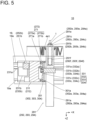
FIG. 5 is a cross-sectional view taken along line V-V inFIG. 4 . -
FIG. 6 is a cross-sectional view taken along line VI-VI inFIG. 4 . -
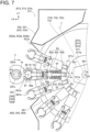
FIG.7 shows a view along an arrow VII inFIG. 1 . -
FIG. 8 is a cross-sectional view taken along line VIII-VIII inFIG. 7 . - As shown in
FIGs. 1 and2 , alateral processing machine 10 according to an embodiment includes abed 11, a pair of floor surface X-axis guides 13, a pair of fixedsupport columns 15, a fixedbeam 17, an upperX-axis guide 19, a firstprocessing unit group 20, a secondprocessing unit group 22, a bellows cover (expansion cover) 40, a first ATC (first automatic tool changer) 511, a second ATC (second automatic tool changer) 512, a third ATC (third automatic tool changer) 513, and a fourth ATC (fourth automatic tool changer) 514. - For convenience, the left-right direction is defined as an X direction (the left as viewed from the front is defined as +X direction), the vertical direction is defined as a Y direction (the upward is defined as +Y direction), and the front-rear direction is defined as a Z direction (the back as viewed from the front is defined as +Z direction).
- As shown in
FIG. 3 , the floorsurface X-axis guide 13 includes a lowerX guide rail 13a and a lowerX guide block 13b. The floorsurface X-axis guide 13 extends in X direction. The lowerX guide rail 13a, which extends in X direction, is fixed to the upper surface of thebed 11. The lowerX guide block 13b, which is disposed on the lowerX guide rail 13a, moves in X direction. - As shown in
FIG. 2 , the pair of fixedsupport columns 15 are disposed at both end portions of thebed 11 in X direction. The fixedsupport column 15 includes amain column 15a and a sub-column 15b. The fixedsupport column 15 has a closed shape when viewed from Y direction. The sub-column 15b is disposed frontward (-Z direction) from themain column 15a. - The fixed
beam 17 is bridged between the upper end portions of the pair of fixedsupport columns 15. The fixedbeam 17 extends in X direction. As shown inFIG. 4 , the upperX-axis guide 19 includes an upperX guide rail 19a and an upperX guide block 19b. The upperX guide rail 19a, which extends in X direction, is fixed to the rear surface of the fixedbeam 17. The upperX guide block 19b, which is disposed on the upperX guide rail 19a, moves in X direction. - As shown in
FIGs. 3 to 6 , the firstprocessing unit group 20 includes a first movingcolumn 211, a first lowerX-axis driving device 231, a first upperX-axis driving device 251, a first Y-axis guide 271, afirst Y base 301, afirst processing unit 291, a first Y-axis driving device 331, asecond Y base 302, asecond processing unit 292, and a second Y-axis driving device 332. - As shown in
FIG. 3 , the first movingcolumn 211 includes abase portion 211a and acolumn portion 211b. Thebase portion 211a is fastened to the lowerX guide block 13b. Thebase portion 211a has a rectangular parallelepiped shape. Thecolumn portion 211b is disposed in -X direction of thebase portion 211a. Thecolumn portion 211b has, for example, a rectangular cross-section. Thecolumn portion 211b has an upper end portion fastened to the upperX guide block 19b. - As shown in
FIG. 4 , the first lowerX-axis driving device 231 includes a lower Xhelical rack 231a, a firstlower X motor 231b, and a first lower Xhelical gear 231c. The lower Xhelical rack 231a, which extends in X direction, is fixed to thebed 11. The firstlower X motor 231b is disposed on thebase portion 211a. The first lower Xhelical gear 231c, which is connected to the firstlower X motor 231b, meshes with the lower Xhelical rack 231a. - As shown in
FIG. 4 , the first upperX-axis driving device 251 includes an upper Xhelical rack 251a, a firstupper X motor 251b, and a first upper Xhelical gear 251c. The upper Xhelical rack 251a, which extends in X direction, is fixed to the rear surface of the fixedbeam 17. The firstupper X motor 251b is fastened in the upper portion of thecolumn portion 211b. The firstupper X motor 251b rotates in synchronization with the firstlower X motor 231b. The first upper Xhelical gear 251c, which is connected to the firstupper X motor 251b, meshes with the upper Xhelical rack 251a. - As shown in
FIG. 3 , the first Y-axis guide 271 includes aY guide rail 271a and a plurality of Y guide blocks 271b. TheY guide rail 271a, which extends in Y direction, is disposed in +X direction of the first movingcolumn 211. TheY guide block 271b, which is disposed on theY guide rail 271a, moves in Y direction. - The
first Y base 301 is fastened to theY guide block 271b. Thefirst Y base 301 may include a bolt (first fastening member) 301a. - The
second Y base 302 is fastened to theY guide block 271b. Thesecond Y base 302 may include a bolt (second fastening member) 302a. - As shown in
FIG. 5 , the first Y-axis driving device 331 includes a first Yhelical rack 331a, afirst Y motor 331b, and a first Yhelical gear 331c. The first Yhelical rack 331a, which extends in Y direction, is disposed on the first movingcolumn 211. The first Yhelical rack 331a is disposed on a side surface of thecolumn portion 211b in +X direction. - The
first Y motor 331b is fastened to thefirst Y base 301. The first Yhelical gear 331c, which is connected to thefirst Y motor 331b, engages with the first Yhelical rack 331a. - As shown in
FIG. 5 , thefirst processing unit 291 includes afirst body 291a, afirst ram 291b, and afirst spindle 291c. Thefirst body 291a has a prismatic shape extending in Z direction. Thefirst body 291a is coupled to thefirst Y base 301 with thebolt 301a. Thefirst ram 291b protrudes forward of the bellows cover 40 from a distal end portion of thefirst body 291a. Thefirst ram 291b is guided in Z direction. Thefirst ram 291b moves forward and backward in Z direction. Thefirst spindle 291c is rotatably supported by thefirst ram 291b. Thefirst spindle 291c includes afirst spindle hole 291e and anunclamping device 291f. Theunclamping device 291f clamps and unclamps atool 1 mounted in thefirst spindle hole 291e. Thefirst processing unit 291 is removably coupled to thefirst Y base 301. - The
tool 1 is mounted in thefirst spindle hole 291e. As shown inFIGs. 7 and8 , thetool 1 includes a taperedshank 1a (seeFIG. 8 ) and akeyway 1b (seeFIG. 7 ). The taperedshank 1a abuts thefirst spindle hole 291e. - As shown in
FIGs. 2 and5 , the second Y-axis driving device 332 includes a first Yhelical rack 331a, asecond Y motor 332b, and a second Yhelical gear 332c. Thesecond Y motor 332b is fastened to thesecond Y base 302. The second Yhelical gear 332c, which is connected to thesecond Y motor 332b, meshes with the first Yhelical rack 331a. - The
second processing unit 292 includes asecond body 292a, asecond ram 292b, and asecond spindle 292c. Thesecond processing unit 292 is disposed in -Y direction (first Y direction) from thefirst processing unit 291. Thesecond processing unit 292 is detachably coupled to thesecond Y base 302 with asecond fastening member 302a. Thesecond processing unit 292 is substantially identical to thefirst processing unit 291. - As shown in
FIG. 2 , the secondprocessing unit group 22 includes a second column (second moving column) 212, a second lowerX-axis driving device 232, a second upperX-axis driving device 252, asecond Y guide 272, athird Y base 303, athird processing unit 293, a third Y-axis driving device 333, afourth Ybase 304, afourth processing unit 294, and a fourth Y-axis driving device 334. The secondprocessing unit group 22 is disposed in +X direction (first X direction) from the firstprocessing unit group 20. The secondprocessing unit group 22 is symmetrical with respect to a plane YZ from the firstprocessing unit group 20. - As shown in
FIG. 3 , thethird Y base 303 may include athird fastening member 303a. Thefourth Y base 304 may include afourth fastening member 304a. - As shown in
FIG. 4 , the second lowerX-axis driving device 232 includes a lower Xhelical rack 231a, a secondlower X motor 232b, and a second lower Xhelical gear 232c. - The second upper
X-axis driving device 252 includes an upper X helical rack 252a, a secondupper X motor 252b, and a second upper Xhelical gear 232c. - As shown in
FIG. 5 , the third Y-axis driving device 333 includes a second Yhelical rack 332a, athird Y motor 333b, and a third Yhelical gear 333c. - The fourth Y-
axis driving device 334 includes a second Yhelical rack 332a, afourth Y motor 334b, and a fourth Yhelical gear 334c. - The
third processing unit 293 includes athird body 293a, athird ram 293b, and a third spindle 39c. Thethird processing unit 293 is removably coupled to thethird Y base 303. - The
fourth processing unit 294 is disposed in -Y direction (first Y direction) from thethird processing unit 293. Thefourth processing unit 294 includes afourth body 294a, afourth ram 294b, and afourth spindle 294c. Thefourth processing unit 294 is removably coupled to thefourth Y base 304. - The
third processing unit 293 and thefourth processing unit 294 are substantially the same as thefirst processing unit 291. - As shown in
Fig. 6 , the bellows cover 40 includes abox cover 41, afirst X box 431, asecond X box 432, a first X bellows (first X telescopic cover) 451, a second X bellows (second X telescopic cover) 452, a third X bellows (third X telescopic cover) 453, afirst Ybox 441, asecond Y box 442, athird Y box 443, afourth Y box 444, a first Y bellows (first Y telescopic cover) 471, a second Y bellows (second Y telescopic cover) 472, a third Y bellows (third Y telescopic cover) 473, a fourth Y bellows (fourth Y telescopic cover) 474, a fifth Y bellows (fifth Y telescopic cover) 475, and a sixth Y bellows (sixth Y telescopic cover) 476. - The
box cover 41 is fixed to the fixedsupport column 15. Thebox cover 41, which has a box shape, has a large opening in Z direction. - The
first X box 431, which has a box shape extending in Y direction, has a large opening in Z direction. Thefirst X box 431, which is disposed in thebox cover 41, reciprocates in X direction. Thesecond X box 432 is substantially identical to thefirst X box 431. Thesecond X box 432 is disposed in the +X side from thefirst X box 431. - The
first Y box 441, which has a box shape, is disposed inside thefirst X box 431. Thefirst Y box 441 reciprocates in Y direction. As shown inFIG. 4 , thefirst Y box 441 includes abox hole 441a and apacking 441b. Thefirst body 291a extends through thebox hole 441a. The packing 441b seals a gap between thefirst body 291a and thefirst box hole 441a. - The
second Y box 442 includes asecond box hole 442a and asecond packing 442b. Thesecond Y box 442 is substantially identical to thefirst X box 431. - The
third Y box 443 includes athird box hole 443a and athird packing 443b. Thethird Y box 443 is substantially identical to thefirst X box 431. - The
fourth Y box 444 includes afourth box hole 444a and afourth packing 444b. Thefourth Y box 444 is substantially identical to thefirst X box 431. - As shown in
FIG. 6 , the first X bellows 451 is disposed in thebox cover 41 to connect thebox cover 41 and thefirst X box 431. The first X bellows 451 expands and contracts as thefirst X box 431 reciprocates. - The second X bellows 452 is disposed in the
box cover 41 to connect thefirst X box 431 and thesecond X box 432. The second X bellows 452 expands and contracts as thefirst X box 431 and thesecond X box 432 reciprocate. - The third X bellows 453 is disposed in the
box cover 41 to connect thebox cover 41 and thesecond X box 432. The third X bellows 453 expands and contracts as thesecond X box 432 reciprocates. - The first Y bellows 471 is disposed in the
first X box 431 to connect thefirst X box 431 and thefirst Y box 441. The first Y bellows 471 expands and contracts as thefirst Y box 441 reciprocates. - The second Y bellows 472 is disposed in the
first X box 431 to connect thefirst Y box 441 and thesecond Y box 442. The second Y bellows 472 expands and contracts as thefirst Y box 441 and thesecond Y box 442 reciprocate. - The third Y bellows 473 is disposed in the
first X box 431 to connect thefirst X box 431 and thesecond Y box 442. The third Y bellows 473 expands and contracts as thesecond Y box 442 reciprocates. - The fourth Y bellows 474 is disposed in the
second X box 432 to connect thesecond X box 432 and thethird Y box 443. The fourth Y bellows 474 expands and contracts as thethird Y box 443 reciprocates. - The fifth Y bellows 475 is disposed in the
second X box 432 to connect thethird Y box 443 and thefourth Y box 444. The fifth Y bellows 475 expands and contracts as thethird Y box 443 and thefourth Y box 444 reciprocate. - The sixth Y bellows 476 is disposed in the
second X box 432 to connect thesecond X box 432 and thefourth Y box 444. The sixth Y bellows 476 expands and contracts as thefourth Y box 444 reciprocates. - As shown in
FIG. 1 , thefirst ATC 511 and thesecond ATC 512 are disposed in -X direction from the firstprocessing unit group 20. Thesecond ATC 512 is disposed in -Y direction (first Y direction) from thefirst ATC 511. - As shown in
FIGs. 7 and8 , thefirst ATC 511 includes aframe 501, a magazine cover (first magazine cover) 531, a magazine disk (first magazine disk) 551, acam 571, amotor 561, a plurality of tool holding portions (first tool holding portions) 591, a shutter (first shutter) 731, and arotary shaft 581. - For convenience, the
first ATC 511 ofFIG. 7 shows a state of being rotated 120 degrees counterclockwise as viewed from the front from the state ofFIG. 1 . - The
frame 501 extends toward -X direction from the sub-column 15b. Theframe 501 supports themagazine disk 551, themagazine cover 531, thecam 571, and themotor 561. Themotor 561 rotates themagazine disk 551. - The
magazine cover 531 has a tool change port (first tool change port) 531a. Thetool change port 531a is disposed in the first X direction (+X direction) from themagazine cover 531. Thetool change port 531a has a rectangular shape as viewed from X direction. As viewed from the front (-Z direction), thetool change port 531a is C-shaped and recessed in -X direction. - The
magazine disk 551 has therotary shaft 581. Themagazine disk 551 rotates about therotary shaft 581. Themagazine disk 551 is connected to themotor 561. Themotor 561 positions any one of thetool holding portions 591 or ashutter centerline 7 at thetool changing position 81. Theshutter centerline 7 connects theshutter 731 and the center of therotary shaft 581. - The
cam 571 is fixed to theframe 501. Thecam 571 is a disk-shaped plate cam. Thecam 571 has acontour 571a. Thecontour 571a has adistance 571b equal from therotary shaft 581 except for thetool changing position 81. Thecontour 571a is shorter by astroke length 571c from thedistance 571b at thetool changing position 81. - The
tool holding portion 591 includes atool holding portion 591a and atool holding portion 591b. InFIG. 7 , thetool holding portion 591a is located at thetool changing position 81. Thetool holding portion 591b is located other than thetool changing position 81. - The
tool holding portion 591 is disposed on an outer peripheral portion of themagazine disk 551. Thetool holding portion 591 includes a pair of pinch levers 69, apinch pin 70, aroller cam 71, a compression coil spring (first elastic body) 73, a key 72, acylinder 61, aplunger 63, a compression coil spring (second elastic body) 67, and acam follower 65. Hereinafter, the radially outward from themagazine disk 551 is referred to as a distal end direction, and the radially inward from themagazine disk 551 is referred to as a basal end direction. - The
pinch lever 69 includes aclaw portion 69a and alever portion 69b. Theclaw portion 69a is a distal end portion of thepinch lever 69. Theclaw portion 69a holds thetool 1. Thelever portion 69b is a basal end portion of thepinch lever 69. The pair of pinch levers 69 is swingably supported by themagazine disk 551 with thepinch pin 70. Thepinch pin 70 supports a central portion of thepinch lever 69. Thecompression coil spring 73 is disposed between the pair oflever portions 69b to bias thelever portion 69b so as to separate each other. Theroller cam 71 is disposed at a basal end portion of thelever portion 69b. Theroller cam 71 may be omitted. Thecompression coil spring 73 may be omitted. - The key 72 is disposed between the pair of pinch levers 69. The key 72 is fixed to the
magazine disk 551. The key 72 is inserted into thekeyway 1b when thepinch lever 69 holds thetool 1. - The
cylinder 61 includes acylinder chamber 61a and arod hole 61b. Thecylinder 61 has, for example, a prismatic shape. Thecylinder 61 is disposed on themagazine disk 551. Thecylinder chamber 61a extends in a radial direction of themagazine disk 551. Therod hole 61b, which is disposed at the basal end portion of thecylinder 61, is connected to thecylinder chamber 61a. - The
plunger 63 includes a V-plane 63a, apiston 63c, and arod 63b. Theplunger 63 reciprocates in the radial direction inside thecylinder 61. Thepiston 63c slides inside thecylinder chamber 61a. The V-plane 63a is disposed at the distal end of thepiston 63c. The V-plane 63a comes into contact with theroller cams 71. Therod 63b is connected to the basal end of thepiston 63c to extend through therod hole 61b. Thecam follower 65 is disposed at the basal end of therod 63b. - The
compression coil spring 67 is disposed inside thecylinder chamber 61a. Thecompression coil spring 67 biases thepiston 63c toward distal end. - The
shutter 731 is disposed on themagazine disk 551. Theshutter 731 has a rectangular shape as viewed in the radial direction. Theshutter 731, which is C-shaped as viewed from the front (-Z direction), has a central portion recessed radially inward. Theshutter 731 and thetool holding portion 591 rotate integrally with themagazine disk 551. At the processing position 5 (seeFIG. 1 ), theshutter centerline 7 passes through thetool changing position 81. When theshutter 731 is at theprocessing position 5, the shape of theshutter 731 coincides with the shape of thetool change port 531a as viewed from Z-direction. Theshutter 731 covers substantially the entire surface of thetool change port 531a. As themagazine disk 551 rotates, theshutter 731 is housed in themagazine cover 531. - A method of using the
first ATC 511 will be described. - In the
tool holding portion 591b, thecam follower 65 abuts against thecam 571. Theplunger 63 thus cannot move toward the center direction. The V-plane 63a of theplunger 63 comes into contact with theroller cam 71. Further, theplunger 63 is biased toward the distal end by thespring 67. Thepinch lever 69 is thus biased in the closing direction. Thetool 1 held by thetool holding portion 591b is thus prevented from being detached from thetool holding portion 591b. - Referring to
FIGs. 7 and8 , a method of passing thetool 1 mounted on thefirst spindle 291c to thetool holding portion 591 by thefirst spindle 291c will be described. As shown inFIG. 7 , thefirst spindle 291c is stopped in advance so that thekeyway 1b faces -X direction. Then, thefirst spindle 291c moves along thearrow 3 in -X direction to move to thetool changing position 81. At this time, as shown by the two-dot chain line inFIG. 7 , thepinch lever 69 abuts against a flange portion (not shown) of thetool 1 and is pushed open. Thecontour 571a is recessed in +X direction by thestroke length 571c. Theplunger 63 thus moves toward the basal end along the arrow 4 against the elastic force of thespring 67. Then, as theplunger 63 moves, thepinch lever 69 is once opened. When thefirst spindle 291c arrives at thetool changing position 81, the key 72 is received into thekeyway 1b. Theplunger 63 is then pushed back toward the distal end by thespring 67. This closes theclaw portion 69a and thepinch lever 69 holds thetool 1. - Next, as shown in
FIG. 8 , thefirst spindle 291c moves in +Z direction along thearrow 5. As thefirst spindle 291c moves, theunclamping device 291f unclamps thetool 1. As a result, thetool 1 comes out of thefirst spindle hole 291e. Then, thetool 1 is transferred from thefirst spindle 291c to thefirst ATC 511. - When the
first ATC 511 passes thetool 1 to thefirst spindle 291c, it reversely performs the steps of the above-described replacement methods. That is, inFIG. 8 , thefirst spindle 291c moves in the opposite direction (-Z direction) of thearrow 5, and theunclamping device 291f clamps thetool 1. Next, inFIG. 7 , thefirst spindle 291c moves in the opposite direction (+X direction) of thearrow 3. - As shown in
FIGs. 1 and7 , thesecond ATC 512 includes aframe 502, a magazine cover (first magazine cover) 532, a magazine disk (first magazine disk) 552, a cam 572, a motor 562 (seeFIG. 8 ), a plurality of tool holding portions (first tool holding portions) 592, and a shutter (first shutter) 732. Themagazine cover 532 has a tool change port (first tool change port) 532a. Thesecond ATC 512 is substantially the same as thefirst ATC 511. Thesecond ATC 512 is disposed in -Y direction (first Y direction) from thefirst ATC 511. Themagazine cover 532 is integral with themagazine cover 531. - As shown in
FIG. 1 , thethird ATC 513 and the fourth ATC 514 are disposed in the +X side from the secondprocessing unit group 22. Thethird ATC 513 and the fourth ATC 514 are symmetrical to thefirst ATC 511 and thesecond ATC 512 with respect to YZ plane. The fourth ATC 514 is disposed in -Y direction (first Y direction) from thethird ATC 513. When thethird spindle 293c replaces thetool 1 from thethird ATC 513, thethird spindle 293c moves in +X direction and moves to thetool changing position 83. At this time, thefourth spindle 294c moves to thetool changing position 84 in XY plane. - As shown in
FIGs. 1 and7 , thethird ATC 513 includes aframe 503, a magazine cover (second magazine cover) 533, a magazine disk (second magazine disk) 553, acam 573, a motor 563, a plurality of tool holding portions (second tool holding portions) 593, and a shutter (second shutter) 733. Themagazine cover 533 has a tool change port (second tool change port) 533a. - The fourth ATC 514 includes a
frame 504, a magazine cover (second magazine cover) 534, a magazine disk (second magazine disk) 554, acam 574, a motor 564, a plurality of tool holding portions (second tool holding portions) 594, and a shutter (second shutter) 734. Themagazine cover 534 has a tool change port (second tool change port) 534a. Themagazine cover 534 is integral with themagazine cover 533. - The
lateral processing machine 10 according to the present embodiment achieves the following effects. - The bellows cover 40 includes a
first X box 431 and twoY boxes first X box 431 is tilted, thefirst X box 431 is prevented from moving. Then, damage to the first X bellows 451 and the second X bellows 452 is promoted. - In contrast, in the present embodiment, the two
Y boxes first body 291a and thesecond body 292a, respectively. Thefirst body 291a and thesecond body 292a are guided by the first Y-axis guide 271. Thus, when thefirst spindle 291c and thesecond spindle 292c move freely in XYZ direction, thefirst body 291a and thesecond body 292a are positioned parallel to the Y-axis. As a result, the inclination of thefirst X box 431 from the Y direction is suppressed. Thefirst X box 431 is thus moved smoothly. In addition, damage to the first X bellows 451 and the second X bellows 452 is suppressed. - The
second X box 432 is also substantially the same as thefirst X box 431. - The
tool change port 531a and theshutter 731 are recessed in -X direction as viewed from Z direction. Thus, when theshutter 731 is at theprocessing position 5, thefirst spindle 291c can be moved to thetool changing position 81. - Both the
first processing unit 291 and thesecond processing unit 292 are arranged in the first movingcolumn 211. Thefirst spindle 291c moves to thetool changing position 81 when thefirst spindle 291c exchanges thetool 1 with thefirst ATC 511. At the same time, thesecond spindle 292c moves to thetool changing position 83. - When the
first spindle 291c exchanges thetool 1 with thefirst ATC 511, thesecond spindle 292c can simultaneously exchange thetool 1 with thesecond ATC 512. - When the
first spindle 291c exchanges thetool 1 with the first ATC 511while thesecond spindle 292c does not exchange thetool 1 with thesecond ATC 512, theshutter 732 is positioned at theprocessing position 5. At this time, thetool change port 532a and theshutter 732 are recessed in -X direction as viewed from Z direction. Thesecond spindle 292c thus does not collide with thesecond ATC 512. - Even when the
second spindle 292c exchanges thetool 1 with thesecond ATC 512 while thefirst spindle 291c does not exchange thetool 1 with thefirst ATC 511, thefirst spindle 291c does not collide with thefirst ATC 511. - The relationship between the
third spindle 293c, thefourth spindle 294c and thethird ATC 513, the fourth ATC 514 is substantially the same as the relationship between thefirst spindle 291c, thesecond spindle 292c and thefirst ATC 511, thesecond ATC 512. -
- 1
- Tool
- 11
- Bed
- 13
- Floor surface X-axis guide
- 211
- First moving column
- 271
- First Y-axis guide
- 291
- First processing unit
- 291b
- First ram
- 291c
- First spindle
- 292
- Second processing unit
- 292b
- Second ram
- 292c
- Second spindle
- 40
- Bellows cover (expansion cover)
- 41
- Box cover
- 431
- First X Box
- 441
- First Y Box
- 442
- Second Y Box
- 451
- First X bellows (First X telescopic cover)
- 471
- First Y bellows (First Y telescopic cover)
- 472
- Second Y bellows (second Y telescopic cover)
- 473
- Third Y bellows (Third Y telescopic cover)
- 511
- First ATC (First tool changer)
- 512
- Second ATC (Second tool changer)
- 81
- First tool changing position
- 82
- Second tool changing position
Claims (6)
- A lateral processing machine (10), comprising:a bed (11);a floor surface X-axis guide (13) disposed on an upper surface of the bed (11);a first moving column (211) guided by the floor surface X-axis guide (13) to reciprocate in X direction;a first Y-axis guide (271) disposed on the first moving column (211);a first processing unit (291) guided by the first Y-axis guide (271) to reciprocate in Y direction, the first processing unit (291) includes a first ram (291b) that rotatably supports a first spindle (291c) and advances or retracts in Z direction;a second processing unit (292) guided by the first Y-axis guide (271) to reciprocate in Y direction, the second processing unit (292) includes a second ram (292b) that rotatably supports a second spindle (292c) and advances or retract in Z direction; andan expansion cover (40) including,a box cover (41) disposed on the bed (11),a first X box (431) extending in Y direction inside the box cover (41) to reciprocate in X direction together with the first moving column (211),a first X telescopic cover (451) configured to cover between the first X box (431) and the box cover (41),a first Y box (441) receiving the first ram (291b) to extend through, the first Y box (441) configured to reciprocate in Y direction inside the first X box (431),a second Y box (442) receiving the second ram (292b) to extend through, the second Y box (442) configured to reciprocate in Y direction inside the first X box (431),a first Y telescopic cover (471) configured to cover between the first Y box (441) and the first X box (431),a second Y telescopic cover (472) configured to cover between the first Y box (441) and the second Y box (442), anda third Y telescopic cover (473) configured to cover between the second Y box (442) and the first X box (431).
- The lateral processing machine (10) according to claim 1, further comprising:a second moving column (212) disposed in a first X direction (+X) from the first moving column (211), the second moving column (212) guided by the floor surface X-axis guide (13) to reciprocate in X direction;a second Y-axis guide (272) disposed on the second moving column (212);a third processing unit (293) guided by the second Y-axis guide (272) to reciprocate in Y direction, the third processing unit (293) includes a third ram (293b) that rotatably supports a third spindle (293c) and advances or retracts in Z direction;a fourth processing unit (294) guided by the second Y-axis guide (272) to reciprocate in Y direction, the fourth processing unit (294) includes a fourth ram (294b) that rotatably supports a fourth spindle (294c) and advances or retract in Z direction;wherein the expansion cover (40) includes,a second X box (432) extending in Y direction inside the box cover (41) to reciprocate in X direction together with the second moving column (212),a second X telescopic cover (452) configured to cover between the first X box (431) and the second X box (432),a third X telescopic cover (453) configured to cover between the second X box (432) and the box cover (41),a third Y box (443) receiving the third ram (293b) to extend through, the third Y box (443) configured to reciprocate in Y direction inside the second X box (432),a fourth Y box (444) receiving the fourth ram (294b) to extend through, the fourth Y box (444) configured to reciprocate in Y direction inside the second X box (432),a fourth Y telescopic cover (474) configured to cover between the third Y box (443) and the second X box (432),a fifth Y telescopic cover (475) configured to cover between the third Y box (443) and the fourth Y box (444), anda sixth Y telescopic cover (476) configured to cover between the fourth Y box (444) and the second X box (432).
- The lateral processing machine (10) according to claim 1 or 2, further comprising:a pair of fixed support columns (15) disposed at both ends of the bed (11) in X direction;a fixed beam (17) bridged between upper ends of the pair of the fixed support columns (15); andan upper X-axis guide (19) disposed on the fixed beam (17).
- The lateral processing machine (10) according to any one of claims 1 to 3, further comprising:a first lower X-axis driving device (231) disposed on the bed (11) to drive a lower end portion of the first moving column (211) in X direction; anda first upper X-axis driving device (251) disposed above the bed (11) to drive an upper end portion of the first moving column (211) in X direction in synchronization with the first lower X-axis driving device (231).
- The lateral processing machine (10) according to any one of claims 2 to 4,
whereinthe first Y-axis guide (271) is disposed on a lateral side of the first moving column (211) in the first X direction (+X),the first processing unit (291) and the second processing unit (292) are disposed on the lateral side of the first moving column (211) in the first X direction (+X),the second Y-axis guide (272) is disposed on a lateral side of the second moving column (212) in a second X direction (-X), the second X direction (-X) being opposite direction of the first X direction (+X), andthe third processing unit (293) and the fourth processing unit (294) are disposed on the lateral side of the second moving column (212) in the second X direction (-X). - The lateral processing machine (10) according to claim 4, whereinthe first lower X-axis driving device (231) includes,a lower X helical rack (231a) disposed on the bed (11),a first lower X helical gear (231c) configured to mesh with the lower X helical rack (231a), anda lower X motor (231b) connected to the first lower X helical gear (231c), the lower X motor (231b) disposed on a lower end portion of the first moving column (211),the first upper X-axis driving device (251) includes,an upper X helical rack (251a) disposed on the fixed beam (17),a first upper X helical gear (251c) configured to mesh with the upper X helical rack (251a), andan upper X motor (251b) connected to the first upper X helical gear (251c), the upper X motor (251b) disposed on an upper end portion of the first moving column (211).
Applications Claiming Priority (1)
| Application Number | Priority Date | Filing Date | Title |
|---|---|---|---|
| JP2023080267A JP7842058B2 (en) | 2023-05-15 | 2023-05-15 | Horizontal machining center |
Publications (2)
| Publication Number | Publication Date |
|---|---|
| EP4464457A1 EP4464457A1 (en) | 2024-11-20 |
| EP4464457B1 true EP4464457B1 (en) | 2025-06-04 |
Family
ID=90366802
Family Applications (1)
| Application Number | Title | Priority Date | Filing Date |
|---|---|---|---|
| EP24161559.0A Active EP4464457B1 (en) | 2023-05-15 | 2024-03-05 | Lateral processing machine |
Country Status (5)
| Country | Link |
|---|---|
| US (1) | US20240383084A1 (en) |
| EP (1) | EP4464457B1 (en) |
| JP (1) | JP7842058B2 (en) |
| KR (1) | KR20240165263A (en) |
| CN (2) | CN222243811U (en) |
Family Cites Families (13)
| Publication number | Priority date | Publication date | Assignee | Title |
|---|---|---|---|---|
| JPS62218007A (en) * | 1986-03-17 | 1987-09-25 | Honda Motor Co Ltd | Multi-spindle machine tool |
| JPS62218008A (en) * | 1986-03-17 | 1987-09-25 | Honda Motor Co Ltd | Multi-spindle machine tool |
| JPH0418763Y2 (en) * | 1987-01-09 | 1992-04-27 | ||
| JP2002079431A (en) | 2000-09-07 | 2002-03-19 | Ishikawajima Harima Heavy Ind Co Ltd | Flat plate finishing machine |
| JP4514310B2 (en) | 2000-10-27 | 2010-07-28 | エンシュウ株式会社 | Horizontal machine tool column device |
| JP4745612B2 (en) | 2003-01-22 | 2011-08-10 | コマツNtc株式会社 | Machine Tools |
| JP5922554B2 (en) | 2012-10-31 | 2016-05-24 | 株式会社ジャバラ | Telescopic cover device for machine tools |
| KR102058750B1 (en) * | 2013-03-04 | 2019-12-23 | 두산공작기계 주식회사 | Machine tool |
| CN204525023U (en) | 2015-03-05 | 2015-08-05 | 宁波海天精工股份有限公司 | Protection drag plate structure on a kind of high-speed horizontal machining center |
| DE102015105043A1 (en) | 2015-04-01 | 2016-10-06 | Samag Saalfelder Werkzeugmaschinen Gmbh | processing machine |
| DE102017129748A1 (en) | 2017-12-13 | 2019-06-13 | Eurolaser Gmbh | Positioning system and material processing machine |
| CN109262371A (en) | 2018-10-11 | 2019-01-25 | 绍兴大丸精密机械有限公司 | Horizontal machining center |
| JP2024074429A (en) | 2022-11-21 | 2024-05-31 | 株式会社スギノマシン | Horizontal processing machine and horizontal processing system |
-
2023
- 2023-05-15 JP JP2023080267A patent/JP7842058B2/en active Active
-
2024
- 2024-03-05 EP EP24161559.0A patent/EP4464457B1/en active Active
- 2024-03-11 US US18/601,110 patent/US20240383084A1/en active Pending
- 2024-03-28 KR KR1020240042355A patent/KR20240165263A/en active Pending
- 2024-04-02 CN CN202420669644.9U patent/CN222243811U/en active Active
- 2024-04-02 CN CN202410395813.9A patent/CN118951817A/en active Pending
Also Published As
| Publication number | Publication date |
|---|---|
| EP4464457A1 (en) | 2024-11-20 |
| JP2024164640A (en) | 2024-11-27 |
| CN118951817A (en) | 2024-11-15 |
| JP7842058B2 (en) | 2026-04-07 |
| CN222243811U (en) | 2024-12-27 |
| US20240383084A1 (en) | 2024-11-21 |
| KR20240165263A (en) | 2024-11-22 |
Similar Documents
| Publication | Publication Date | Title |
|---|---|---|
| EP2239090B1 (en) | Vertical turret lathe with automatic tool exchanger | |
| CN101036969B (en) | Machine tool and method for machining workpieces, especially metal workpieces | |
| US8409062B2 (en) | Machine tool | |
| US7108647B2 (en) | Tool changer of machine tool | |
| CN209737129U (en) | Tool magazine device and machine tool for fixed beam type gantry multi-spindle machine tool | |
| US5346454A (en) | Turret punch press | |
| JP2026506233A (en) | Horizontal processing machine tools | |
| EP4464457A1 (en) | Lateral processing machine | |
| EP4464459A2 (en) | Lateral processing machine and tool changer | |
| TW202412987A (en) | Tool magazine system of processing machine | |
| JP2024081917A (en) | Tool magazine device and machine tool | |
| CN114749938A (en) | Multi-channel multi-station machining machine tool | |
| JP2977161B2 (en) | Laser multitasking machine | |
| JPH0557549A (en) | Compound laser beam machining unit | |
| JP3353796B2 (en) | Milling equipment | |
| CN221676538U (en) | Tool changing mechanism of CNC machine tools | |
| JP7733584B2 (en) | Additional tool magazine device and machine tool | |
| JP3249741B2 (en) | Machine tools and tool changers | |
| JPH042380B2 (en) | ||
| CN223643363U (en) | Combined machining center | |
| JP2971076B2 (en) | Transfer device of tool changer | |
| CN203390553U (en) | Efficient machine tool | |
| JP3076595B2 (en) | Machine Tools | |
| CN121267635A (en) | Radiator processing production line | |
| JP2023009413A (en) | Machine tool |
Legal Events
| Date | Code | Title | Description |
|---|---|---|---|
| PUAI | Public reference made under article 153(3) epc to a published international application that has entered the european phase |
Free format text: ORIGINAL CODE: 0009012 |
|
| STAA | Information on the status of an ep patent application or granted ep patent |
Free format text: STATUS: THE APPLICATION HAS BEEN PUBLISHED |
|
| AK | Designated contracting states |
Kind code of ref document: A1 Designated state(s): AL AT BE BG CH CY CZ DE DK EE ES FI FR GB GR HR HU IE IS IT LI LT LU LV MC ME MK MT NL NO PL PT RO RS SE SI SK SM TR |
|
| STAA | Information on the status of an ep patent application or granted ep patent |
Free format text: STATUS: REQUEST FOR EXAMINATION WAS MADE |
|
| 17P | Request for examination filed |
Effective date: 20241128 |
|
| RBV | Designated contracting states (corrected) |
Designated state(s): AL AT BE BG CH CY CZ DE DK EE ES FI FR GB GR HR HU IE IS IT LI LT LU LV MC ME MK MT NL NO PL PT RO RS SE SI SK SM TR |
|
| GRAP | Despatch of communication of intention to grant a patent |
Free format text: ORIGINAL CODE: EPIDOSNIGR1 |
|
| STAA | Information on the status of an ep patent application or granted ep patent |
Free format text: STATUS: GRANT OF PATENT IS INTENDED |
|
| GRAS | Grant fee paid |
Free format text: ORIGINAL CODE: EPIDOSNIGR3 |
|
| GRAA | (expected) grant |
Free format text: ORIGINAL CODE: 0009210 |
|
| INTG | Intention to grant announced |
Effective date: 20250409 |
|
| STAA | Information on the status of an ep patent application or granted ep patent |
Free format text: STATUS: THE PATENT HAS BEEN GRANTED |
|
| AK | Designated contracting states |
Kind code of ref document: B1 Designated state(s): AL AT BE BG CH CY CZ DE DK EE ES FI FR GB GR HR HU IE IS IT LI LT LU LV MC ME MK MT NL NO PL PT RO RS SE SI SK SM TR |
|
| REG | Reference to a national code |
Ref country code: GB Ref legal event code: FG4D |
|
| REG | Reference to a national code |
Ref country code: CH Ref legal event code: EP |
|
| REG | Reference to a national code |
Ref country code: DE Ref legal event code: R096 Ref document number: 602024000169 Country of ref document: DE |
|
| REG | Reference to a national code |
Ref country code: IE Ref legal event code: FG4D |
|
| REG | Reference to a national code |
Ref country code: NL Ref legal event code: MP Effective date: 20250604 |
|
| PG25 | Lapsed in a contracting state [announced via postgrant information from national office to epo] |
Ref country code: ES Free format text: LAPSE BECAUSE OF FAILURE TO SUBMIT A TRANSLATION OF THE DESCRIPTION OR TO PAY THE FEE WITHIN THE PRESCRIBED TIME-LIMIT Effective date: 20250604 Ref country code: FI Free format text: LAPSE BECAUSE OF FAILURE TO SUBMIT A TRANSLATION OF THE DESCRIPTION OR TO PAY THE FEE WITHIN THE PRESCRIBED TIME-LIMIT Effective date: 20250604 |
|
| REG | Reference to a national code |
Ref country code: LT Ref legal event code: MG9D |
|
| PG25 | Lapsed in a contracting state [announced via postgrant information from national office to epo] |
Ref country code: GR Free format text: LAPSE BECAUSE OF FAILURE TO SUBMIT A TRANSLATION OF THE DESCRIPTION OR TO PAY THE FEE WITHIN THE PRESCRIBED TIME-LIMIT Effective date: 20250905 Ref country code: NO Free format text: LAPSE BECAUSE OF FAILURE TO SUBMIT A TRANSLATION OF THE DESCRIPTION OR TO PAY THE FEE WITHIN THE PRESCRIBED TIME-LIMIT Effective date: 20250904 |
|
| PG25 | Lapsed in a contracting state [announced via postgrant information from national office to epo] |
Ref country code: PL Free format text: LAPSE BECAUSE OF FAILURE TO SUBMIT A TRANSLATION OF THE DESCRIPTION OR TO PAY THE FEE WITHIN THE PRESCRIBED TIME-LIMIT Effective date: 20250604 |
|
| PG25 | Lapsed in a contracting state [announced via postgrant information from national office to epo] |
Ref country code: BG Free format text: LAPSE BECAUSE OF FAILURE TO SUBMIT A TRANSLATION OF THE DESCRIPTION OR TO PAY THE FEE WITHIN THE PRESCRIBED TIME-LIMIT Effective date: 20250604 |
|
| PG25 | Lapsed in a contracting state [announced via postgrant information from national office to epo] |
Ref country code: HR Free format text: LAPSE BECAUSE OF FAILURE TO SUBMIT A TRANSLATION OF THE DESCRIPTION OR TO PAY THE FEE WITHIN THE PRESCRIBED TIME-LIMIT Effective date: 20250604 |
|
| PG25 | Lapsed in a contracting state [announced via postgrant information from national office to epo] |
Ref country code: RS Free format text: LAPSE BECAUSE OF FAILURE TO SUBMIT A TRANSLATION OF THE DESCRIPTION OR TO PAY THE FEE WITHIN THE PRESCRIBED TIME-LIMIT Effective date: 20250904 |
|
| PG25 | Lapsed in a contracting state [announced via postgrant information from national office to epo] |
Ref country code: LV Free format text: LAPSE BECAUSE OF FAILURE TO SUBMIT A TRANSLATION OF THE DESCRIPTION OR TO PAY THE FEE WITHIN THE PRESCRIBED TIME-LIMIT Effective date: 20250604 |
|
| PG25 | Lapsed in a contracting state [announced via postgrant information from national office to epo] |
Ref country code: NL Free format text: LAPSE BECAUSE OF FAILURE TO SUBMIT A TRANSLATION OF THE DESCRIPTION OR TO PAY THE FEE WITHIN THE PRESCRIBED TIME-LIMIT Effective date: 20250604 |
|
| PG25 | Lapsed in a contracting state [announced via postgrant information from national office to epo] |
Ref country code: PT Free format text: LAPSE BECAUSE OF FAILURE TO SUBMIT A TRANSLATION OF THE DESCRIPTION OR TO PAY THE FEE WITHIN THE PRESCRIBED TIME-LIMIT Effective date: 20251006 |
|
| REG | Reference to a national code |
Ref country code: AT Ref legal event code: MK05 Ref document number: 1799914 Country of ref document: AT Kind code of ref document: T Effective date: 20250604 |
|
| PG25 | Lapsed in a contracting state [announced via postgrant information from national office to epo] |
Ref country code: IS Free format text: LAPSE BECAUSE OF FAILURE TO SUBMIT A TRANSLATION OF THE DESCRIPTION OR TO PAY THE FEE WITHIN THE PRESCRIBED TIME-LIMIT Effective date: 20251004 |
|
| PG25 | Lapsed in a contracting state [announced via postgrant information from national office to epo] |
Ref country code: SM Free format text: LAPSE BECAUSE OF FAILURE TO SUBMIT A TRANSLATION OF THE DESCRIPTION OR TO PAY THE FEE WITHIN THE PRESCRIBED TIME-LIMIT Effective date: 20250604 Ref country code: AT Free format text: LAPSE BECAUSE OF FAILURE TO SUBMIT A TRANSLATION OF THE DESCRIPTION OR TO PAY THE FEE WITHIN THE PRESCRIBED TIME-LIMIT Effective date: 20250604 |
|
| PG25 | Lapsed in a contracting state [announced via postgrant information from national office to epo] |
Ref country code: CZ Free format text: LAPSE BECAUSE OF FAILURE TO SUBMIT A TRANSLATION OF THE DESCRIPTION OR TO PAY THE FEE WITHIN THE PRESCRIBED TIME-LIMIT Effective date: 20250604 |
|
| PG25 | Lapsed in a contracting state [announced via postgrant information from national office to epo] |
Ref country code: EE Free format text: LAPSE BECAUSE OF FAILURE TO SUBMIT A TRANSLATION OF THE DESCRIPTION OR TO PAY THE FEE WITHIN THE PRESCRIBED TIME-LIMIT Effective date: 20250604 |
|
| PG25 | Lapsed in a contracting state [announced via postgrant information from national office to epo] |
Ref country code: SK Free format text: LAPSE BECAUSE OF FAILURE TO SUBMIT A TRANSLATION OF THE DESCRIPTION OR TO PAY THE FEE WITHIN THE PRESCRIBED TIME-LIMIT Effective date: 20250604 |
|
| PG25 | Lapsed in a contracting state [announced via postgrant information from national office to epo] |
Ref country code: IT Free format text: LAPSE BECAUSE OF FAILURE TO SUBMIT A TRANSLATION OF THE DESCRIPTION OR TO PAY THE FEE WITHIN THE PRESCRIBED TIME-LIMIT Effective date: 20250604 |
|
| REG | Reference to a national code |
Ref country code: DE Ref legal event code: R097 Ref document number: 602024000169 Country of ref document: DE |
|
| PLBE | No opposition filed within time limit |
Free format text: ORIGINAL CODE: 0009261 |
|
| STAA | Information on the status of an ep patent application or granted ep patent |
Free format text: STATUS: NO OPPOSITION FILED WITHIN TIME LIMIT |
|
| PG25 | Lapsed in a contracting state [announced via postgrant information from national office to epo] |
Ref country code: DK Free format text: LAPSE BECAUSE OF FAILURE TO SUBMIT A TRANSLATION OF THE DESCRIPTION OR TO PAY THE FEE WITHIN THE PRESCRIBED TIME-LIMIT Effective date: 20250604 |
|
| PGFP | Annual fee paid to national office [announced via postgrant information from national office to epo] |
Ref country code: DE Payment date: 20260319 Year of fee payment: 3 |
|
| REG | Reference to a national code |
Ref country code: CH Ref legal event code: L10 Free format text: ST27 STATUS EVENT CODE: U-0-0-L10-L00 (AS PROVIDED BY THE NATIONAL OFFICE) Effective date: 20260416 |
|
| PGFP | Annual fee paid to national office [announced via postgrant information from national office to epo] |
Ref country code: FR Payment date: 20260323 Year of fee payment: 3 |
|
| 26N | No opposition filed |
Effective date: 20260305 |