EP4464229A1 - Automatic cleaning apparatus and system - Google Patents
Automatic cleaning apparatus and system Download PDFInfo
- Publication number
- EP4464229A1 EP4464229A1 EP22919792.6A EP22919792A EP4464229A1 EP 4464229 A1 EP4464229 A1 EP 4464229A1 EP 22919792 A EP22919792 A EP 22919792A EP 4464229 A1 EP4464229 A1 EP 4464229A1
- Authority
- EP
- European Patent Office
- Prior art keywords
- dust box
- side wall
- cleaning device
- automatic cleaning
- dust
- Prior art date
- Legal status (The legal status is an assumption and is not a legal conclusion. Google has not performed a legal analysis and makes no representation as to the accuracy of the status listed.)
- Pending
Links
Images






Classifications
-
- A—HUMAN NECESSITIES
- A47—FURNITURE; DOMESTIC ARTICLES OR APPLIANCES; COFFEE MILLS; SPICE MILLS; SUCTION CLEANERS IN GENERAL
- A47L—DOMESTIC WASHING OR CLEANING; SUCTION CLEANERS IN GENERAL
- A47L9/00—Details or accessories of suction cleaners, e.g. mechanical means for controlling the suction or for effecting pulsating action; Storing devices specially adapted to suction cleaners or parts thereof; Carrying-vehicles specially adapted for suction cleaners
- A47L9/10—Filters; Dust separators; Dust removal; Automatic exchange of filters
- A47L9/14—Bags or the like; Rigid filtering receptacles; Attachment of, or closures for, bags or receptacles
- A47L9/1409—Rigid filtering receptacles
-
- A—HUMAN NECESSITIES
- A47—FURNITURE; DOMESTIC ARTICLES OR APPLIANCES; COFFEE MILLS; SPICE MILLS; SUCTION CLEANERS IN GENERAL
- A47L—DOMESTIC WASHING OR CLEANING; SUCTION CLEANERS IN GENERAL
- A47L11/00—Machines for cleaning floors, carpets, furniture, walls, or wall coverings
- A47L11/40—Parts or details of machines not provided for in groups A47L11/02 - A47L11/38, or not restricted to one of these groups, e.g. handles, arrangements of switches, skirts, buffers, levers
- A47L11/4036—Parts or details of the surface treating tools
-
- A—HUMAN NECESSITIES
- A47—FURNITURE; DOMESTIC ARTICLES OR APPLIANCES; COFFEE MILLS; SPICE MILLS; SUCTION CLEANERS IN GENERAL
- A47L—DOMESTIC WASHING OR CLEANING; SUCTION CLEANERS IN GENERAL
- A47L11/00—Machines for cleaning floors, carpets, furniture, walls, or wall coverings
- A47L11/24—Floor-sweeping machines, motor-driven
-
- A—HUMAN NECESSITIES
- A47—FURNITURE; DOMESTIC ARTICLES OR APPLIANCES; COFFEE MILLS; SPICE MILLS; SUCTION CLEANERS IN GENERAL
- A47L—DOMESTIC WASHING OR CLEANING; SUCTION CLEANERS IN GENERAL
- A47L11/00—Machines for cleaning floors, carpets, furniture, walls, or wall coverings
- A47L11/40—Parts or details of machines not provided for in groups A47L11/02 - A47L11/38, or not restricted to one of these groups, e.g. handles, arrangements of switches, skirts, buffers, levers
- A47L11/4013—Contaminants collecting devices, i.e. hoppers, tanks or the like
-
- A—HUMAN NECESSITIES
- A47—FURNITURE; DOMESTIC ARTICLES OR APPLIANCES; COFFEE MILLS; SPICE MILLS; SUCTION CLEANERS IN GENERAL
- A47L—DOMESTIC WASHING OR CLEANING; SUCTION CLEANERS IN GENERAL
- A47L11/00—Machines for cleaning floors, carpets, furniture, walls, or wall coverings
- A47L11/40—Parts or details of machines not provided for in groups A47L11/02 - A47L11/38, or not restricted to one of these groups, e.g. handles, arrangements of switches, skirts, buffers, levers
- A47L11/4091—Storing or parking devices, arrangements therefor; Means allowing transport of the machine when it is not being used
-
- A—HUMAN NECESSITIES
- A47—FURNITURE; DOMESTIC ARTICLES OR APPLIANCES; COFFEE MILLS; SPICE MILLS; SUCTION CLEANERS IN GENERAL
- A47L—DOMESTIC WASHING OR CLEANING; SUCTION CLEANERS IN GENERAL
- A47L9/00—Details or accessories of suction cleaners, e.g. mechanical means for controlling the suction or for effecting pulsating action; Storing devices specially adapted to suction cleaners or parts thereof; Carrying-vehicles specially adapted for suction cleaners
- A47L9/10—Filters; Dust separators; Dust removal; Automatic exchange of filters
- A47L9/12—Dry filters
- A47L9/122—Dry filters flat
-
- A—HUMAN NECESSITIES
- A47—FURNITURE; DOMESTIC ARTICLES OR APPLIANCES; COFFEE MILLS; SPICE MILLS; SUCTION CLEANERS IN GENERAL
- A47L—DOMESTIC WASHING OR CLEANING; SUCTION CLEANERS IN GENERAL
- A47L9/00—Details or accessories of suction cleaners, e.g. mechanical means for controlling the suction or for effecting pulsating action; Storing devices specially adapted to suction cleaners or parts thereof; Carrying-vehicles specially adapted for suction cleaners
- A47L9/10—Filters; Dust separators; Dust removal; Automatic exchange of filters
- A47L9/14—Bags or the like; Rigid filtering receptacles; Attachment of, or closures for, bags or receptacles
- A47L9/1427—Means for mounting or attaching bags or filtering receptacles in suction cleaners; Adapters
- A47L9/1463—Means for mounting or attaching bags or filtering receptacles in suction cleaners; Adapters specially adapted for rigid filtering receptacles
-
- A—HUMAN NECESSITIES
- A47—FURNITURE; DOMESTIC ARTICLES OR APPLIANCES; COFFEE MILLS; SPICE MILLS; SUCTION CLEANERS IN GENERAL
- A47L—DOMESTIC WASHING OR CLEANING; SUCTION CLEANERS IN GENERAL
- A47L9/00—Details or accessories of suction cleaners, e.g. mechanical means for controlling the suction or for effecting pulsating action; Storing devices specially adapted to suction cleaners or parts thereof; Carrying-vehicles specially adapted for suction cleaners
- A47L9/28—Installation of the electric equipment, e.g. adaptation or attachment to the suction cleaner; Controlling suction cleaners by electric means
- A47L9/2868—Arrangements for power supply of vacuum cleaners or the accessories thereof
- A47L9/2873—Docking units or charging stations
-
- A—HUMAN NECESSITIES
- A47—FURNITURE; DOMESTIC ARTICLES OR APPLIANCES; COFFEE MILLS; SPICE MILLS; SUCTION CLEANERS IN GENERAL
- A47L—DOMESTIC WASHING OR CLEANING; SUCTION CLEANERS IN GENERAL
- A47L2201/00—Robotic cleaning machines, i.e. with automatic control of the travelling movement or the cleaning operation
-
- A—HUMAN NECESSITIES
- A47—FURNITURE; DOMESTIC ARTICLES OR APPLIANCES; COFFEE MILLS; SPICE MILLS; SUCTION CLEANERS IN GENERAL
- A47L—DOMESTIC WASHING OR CLEANING; SUCTION CLEANERS IN GENERAL
- A47L2201/00—Robotic cleaning machines, i.e. with automatic control of the travelling movement or the cleaning operation
- A47L2201/02—Docking stations; Docking operations
- A47L2201/024—Emptying dust or waste liquid containers
-
- A—HUMAN NECESSITIES
- A47—FURNITURE; DOMESTIC ARTICLES OR APPLIANCES; COFFEE MILLS; SPICE MILLS; SUCTION CLEANERS IN GENERAL
- A47L—DOMESTIC WASHING OR CLEANING; SUCTION CLEANERS IN GENERAL
- A47L2201/00—Robotic cleaning machines, i.e. with automatic control of the travelling movement or the cleaning operation
- A47L2201/04—Automatic control of the travelling movement; Automatic obstacle detection
Definitions
- the step portion 205 of the accommodating chamber 200 extending around the top edge of the accommodating chamber 200 can completely accommodate the edge of the top cover 302, so that the top cover 302 may be basically tightly accommodated in the accommodating chamber 200, which can prevent foreign objects from falling directly into the edge gap of the dust box, further preventing the dust box from getting stuck, and at the same time ensuring the aesthetic appearance of the top cover as the upper surface of the automatic cleaning device.
- a support structure 3023 is provided below the second portion 3022 of the top cover 302, and configured to support the second portion 3022 of the top cover.
- the support structure 3023 is integrally formed with at least a portion of the accommodating portion 301 to enhance the support force of the support structure 3023 on the second portion 3022 of the top cover 302, effectively preventing damage to the second portion 3022.
- the support structure 3023 may include, but is not limited to, an arc-shaped structure and a linear structure.
- the support structure 3023 is two symmetrically provided arc-shaped structures that substantially match the outer edge contour of the second portion 3022 of the top cover 302.
- the lower surface of the second chamber 202 includes a groove 2021.
- the groove 2021 substantially matches with the contour of the support structure 3023, and is configured such that when the second portion of the top cover is accommodated in the second chamber, the support structure 3023 is accommodated in the groove 2021, so that the upper surface of the top cover 302 is basically horizontal.
- the top cover is symmetrically provided along the central axis of the forward direction of the automatic cleaning device.
- the top cover has at least one or a combination of the following shapes: D shape, rectangular, square, circular, elliptical, triangular, quadrilateral, pentagon, hexagon, heptagon or octagon, as shown in FIG. 6a - FIG. 6h .
- the symmetrical arrangement can make the appearance of the machine more beautiful without the cover, and it is more convenient for the installation and removal of the dust box.
- the above-mentioned embodiments relate to a dust box of an automatic cleaning device and its mounting structure.
- An accommodating chamber is provided on a rear side of a forward direction of the automatic cleaning device.
- the accommodating chamber includes a first chamber and a second chamber.
- the depth of the first chamber is greater than the depth of the second chamber.
- the existing automatic cleaning device is provided with a pop-up dust box or a non-pop-up dust box.
- the pop-up dust box is provided with a top cover and a flip mechanism. When taking and placing the dust box, the top cover needs to be opened, and then the dust box is ejected by pressing the dust box.
- This implementation requires a complex dust box ejection mechanism, which includes a plurality of parts such as springs. Due to repeated use of the spring, the elasticity decreases, making it impossible for the dust box to pop up smoothly. In addition, many other parts and components can easily cause the dust box to not pop up normally, affecting its use.
- the non-pop-up dust boxes often adopts a complex locking structure, in which the spring assembly is prone to aging and damage, and the pressing component is not comfortable enough to match the finger during operation, resulting in a poor overall user experience.
- an automatic cleaning device includes: a moving platform 100, configured to automatically move on an operating surface and including an accommodating chamber 200 provided on a rear side in a forward direction; and a cleaning module, including a dust box 300.
- the dust box 300 is detachably assembled in the accommodating chamber 200; and the dust box includes an accommodating portion 301, a top cover 302 provided above the accommodating portion, and a locking mechanism.
- the locking mechanism includes a first locking mechanism 610 substantially provided at a central axis of the top cover.
- the first locking mechanism 610 includes at least a first catcher recess 603 and a first positive locking member 601.
- the first positive locking member 601 is provided in the first catcher recess 603.
- the first positive locking member 601 can elastically move relative to the first catcher recess 603 under the action of an external force.
- the first catcher recess 603 is formed downwards along an edge of a first portion of the top cover.
- the first catcher recess 603 provides a sufficient depth in the Z direction so that the height of the first positive locking member 601 is lower than the surface of the top cover.
- the first catcher recess 603 provides a sufficient elastic space in the X direction so that when the first positive locking member 601 elastically moves inwards, there is sufficient activity space.
- the catcher surface extends to a position that is generally flush with the top cover.
- the catcher surface may be an arc structure, that is, its projection on the horizontal plane is an arc.
- the catcher surface is convenient for receiving manual operation, and is more in line with the force relationship of ergonomics with the finger shape.
- the first snapping-fit portion 6013 is a pair of sheet-like structures symmetrically provided along two sides of the first elastic arm 6011. The width of the sheet-like structure decreases from a root to a free end, so as to facilitate smooth insertion of the first locking member 701.
- the first elastic arm 6011 may be made of common elastic materials, such as plastic or organic elastic materials.
- FIG. 8 is an enlarged schematic diagram of the first locking member at position A in FIG. 3a .
- the first locking member 701 is provided on an inner wall of the accommodating chamber 200 at a position substantially corresponding to the first positive locking member 601.
- the first positive locking member 601 cooperates with the first locking member 701 to achieve locking.
- the first locking member 701 is a pair of through holes. The free end of the sheet-like structure is inserted into the through hole to achieve locking.
- a first recess 206 is provided on the inner wall of the accommodating chamber at a position substantially corresponding to the first catcher recess 603.
- the pair of through holes are provided on two sides of the first recess 206.
- the locking mechanism further includes a second locking mechanism 620.
- the second locking mechanism 620 includes a second catcher recess 605 and a second positive locking member 602.
- the second catcher recess 605 forms a notch inwardly along the approximate midline position of the second portion 3022 of the top cover, such as an arc-shaped or square notch, to facilitate the insertion of a finger for snapping-fit operations.
- the second positive locking member 602 is provided on the lower side of the second catcher recess 605.
- the second catcher recess 605 provides sufficient space for a finger to control the second positive locking member 602.
- the second positive locking member 602 elastically moves inwards under action of an external force.
- the second positive locking member 602 includes a second elastic arm 6021, a second catcher portion 6022 and a second snapping-fit portion 6023.
- the second elastic arm 6021 is provided below the second catcher recess 605.
- the second elastic arm 6021 includes two symmetrical parts. Each of the second elastic arms 6021 first extends along an opening direction of the second catcher recess 605, then extends along an edge direction of the top cover, and then extends along an edge direction of the second catcher recess 605.
- the opening direction of the second catcher recess 605 is as shown in FIG. 9a , which is the A direction from the center of the top cover to the outside; and in this embodiment, it is also the rear direction of the dust box top cover.
- the two parts of the second elastic arm 6021 are symmetrically connected substantially as two structures in the shape of IL.
- the second catcher portion 6022 connects the two parts of the second elastic arms 6021 that are symmetrically provided.
- the second catcher portion 6022 is provided above the two second elastic arms, as shown in FIG. 9b and FIG. 9c.
- FIG. 9c is an enlarged view of the second catcher portion at position C in FIG. 9b .
- the bottom of the second catcher portion 6022 includes a bottom surface 60221 that protrudes generally outwards and an catcher surface 60222 that extends upwards along the bottom surface. The catcher surface extends to a position that is generally flush with the top cover.
- the catcher surface may be an arc-shaped structure, which is convenient for receiving manual operation and for fingers to apply force.
- the second catcher portion 6022 is integrally formed with the symmetrically provided second elastic arms 6021.
- the second snapping-fit portion 6023 is provided on the lateral extension portion of the second elastic arm.
- the second snapping-fit portion 6023 is a pair of portions symmetrically provided along two sides of the second elastic arm 6021, for example, protrusions or sheet-like structures extending along the A direction.
- each of the second snapping-fit portions 6023 includes a groove extending inwards from the end of the second snapping-fit portion 6023.
- the second positive locking member 602 further includes a symmetrically provided connecting member 6024.
- the connecting member 6024 is substantially planar.
- One end of the second elastic arm 6021 is connected to one side of the connecting member 6024.
- the other side of the connecting member 6024 is connected and fixed to the end face of the support structure.
- the second catcher portion 6022 exposes the second catcher recess 605 in the X direction, so that when unlocking, a finger may be inserted into the second catcher recess 605 and press on the second catcher portion 6022, applying force to the inside of the dust box along the X axis and driving the second snapping-fit portion 6023 to elastically contract inwards, so that the second snapping-fit portion 6023 pops out from the bottom of the second locking member 702 to achieve unlocking.
- the second elastic arm 6021 may be made of common elastic materials, such as plastic or organic elastic materials.
- FIG. 10 is an enlarged view of the second locking member 702 shown at position B in FIG. 3b .
- the second locking member 702 is provided on the inner wall of the accommodating chamber 200 at a position substantially corresponding to the second positive locking member 602.
- the second positive locking member cooperates with the second locking member to achieve locking.
- the second locking member is a pair of protrusions.
- the second snapping-fit portion 6023 extends onto the bottom of the second locking member 702 to achieve locking.
- the protrusion may be flat, cylindrical, rectangular, etc., which is not limited, as long as it can lock the second snapping-fit portion.
- a second recess 207 is provided on the lower surface of the second chamber 202 at a position substantially corresponding to the second catcher recess 605.
- the pair of protrusions are provided on the rear side wall of the second chamber 202 in the same height, and above the second recess 207.
- the second recess 207 is configured to avoid and accommodate the second positive locking member 602 when the dust box 300 is placed in the accommodating chamber 200, so that the entire dust box may be better placed in place in the accommodating chamber 200.
- the top cover includes a first portion covering the accommodating portion and a second portion protruding from the accommodating portion and extending outwards.
- the second catcher recess 605 and the second positive locking member 602 are provided in the second portion of the top cover.
- the second portion of the top cover includes a support structure 3023 on the lower part, which is configured to support the second portion of the top cover.
- the second positive locking member 602 is provided on the support structure 3023.
- the symmetrically provided support structures 3023 form a space compressed inwards in the X direction.
- locking structures are symmetrically provided in the front and rear directions of the top cover of the dust box, so that when a single hand applies a force to the two elastic structures in front and back of the dust box, unlocking may be achieved, and the dust box will not tilt due to the dust box being ejected from one side after only one side is unlocked.
- elastic unlocking may be achieved by only using elastic materials to form elastic arms, avoiding the risk of damage to complex unlocking devices such as springs.
- the second locking mechanism 620 includes at least one first magnetic module 604.
- the first magnetic module 604 is provided between the second portion of the top cover and the supporting structure.
- the accommodating chamber includes at least one second magnetic module 606, which is configured to cooperate with the first magnetic module 604 to achieve locking after being magnetized.
- the first positive locking member 601 and the second catcher recess 605 may be pushed back by a hand to retract the first positive locking member 601 corresponding to the dust box.
- the first snapping-fit portion 6013 on the first positive locking member 601 will automatically pop out and is inserted into the first locking member 701, and the first magnetic module 604 and the second magnetic module 606 are magnetized to each other, thus realizing the locking of the dust box.
- the locking structure is simple and easy to operate, which facilitates the locking of the dust box.
- the second locking mechanism 620 described above may be an implementation including the second catcher recess 605 and the second positive locking member 602, or an implementation including the first magnetic module 604, or an implementation including both of the above, which is not limited.
- the existing automatic cleaning device needs to be equipped with a dust box including a replaceable dust box filter.
- the traditional filter is generally made of a hard frame made of plastic or metal.
- the stacked filter element is placed in the frame, and the frame and the filter element are connected and sealed by glue peripherally. Then, a sealing strip is pasted on the frame to seal the gap between the filter and the dust box. Therefore, in the traditional filter part of the dust box, the is complex, the installation steps of the filter are cumbersome, and it wastes labor and costs.
- the glue used for sealing is not economical and environmentally friendly.
- inventions of the present disclosure provide an automatic cleaning device.
- the automatic cleaning device includes: a moving platform, configured to automatically move on an operating surface and including an accommodating chamber; and a cleaning module, including a dust box.
- the dust box is detachably mounted in the accommodating chamber, the dust box includes a dust box filter, the dust box filter is applied to the dust box of the automatic cleaning device, simplifying the assembly process of the dust box filter.
- This embodiment briefly describes some structural features compared to the above-mentioned embodiments. The same structure produces the same technical effect, and some technical effects are not repeated here. In particular, as shown in FIG. 11- FIG.
- the dust box filter 500 includes: a soft rubber frame 501, the soft rubber frame including at least one soft rubber protrusion 5011 used to seal the assembly gap with the dust box during the assembly process; and a filter element 502, sleeved in the soft rubber frame 501.
- the soft rubber frame 501 is non-detachably connected to the filter element 502.
- the non-detachable connection process between the soft rubber frame 501 and the filter element 502 may adopt a plastic injection molding process, in which the filter element is sleeved in the frame in advance, and then the soft rubber is applied to the sleeved frame assembly to integrally form a plurality of required sealing protrusions.
- a double-shot process may be used to first inject the hard rubber frame body, and then the filter element is mounted on the frame body, and then the soft rubber is injected to form the inner and outer sealing protrusions.
- the soft rubber frame may be a rectangular, square, oval, circular, polygonal or other structure, and this structure is not limited.
- the soft rubber frame is a rectangular structure.
- the soft rubber frame of the rectangular structure includes two first side walls 50111 and two second side walls 50113 provided opposite to each other.
- the soft rubber protrusions include a first protrusion 5011 distributed on the outer peripheral surface of one of the first side walls 50111 and a second protrusion 5015 distributed on the outer peripheral surface of the other first side wall 50111.
- a pair of first side walls 50111 and a pair of second side walls 50113 form a rectangular structure frame, and a filter element is sleeved inside the frame of rectangular structure, as shown in FIG. 11 and FIG. 12 .
- the first protrusion 5011 and the second protrusion 5015 may be continuous protrusion structures.
- the first protrusion 5011 and the second protrusion 5015 extend continuously from one end of the outer peripheral surface of the first side wall 50111 to the other end. Since the first protrusion 5011 and the second protrusion 5015 are soft rubber structures, when the dust box filter is assembled on the dust box, the first protrusion 5011 and the second protrusion 5015 will be squeezed and directly sealed between the dust box filter 500 and the second opening 3012 of the dust box, and fully contact and seal with the inner wall of the second opening 3012 of the dust box extending substantially in the horizontal direction, replacing the traditional step of sealing with a sealing strip after the dust box filter is assembled on the dust box.
- At least one of the first protrusion and the second protrusion is an inverted structure.
- the inverted structure is configured to seal the gap between the soft rubber frame and the dust box assembly while preventing the dust box filter from falling off the dust box.
- the inverted structure is an arc structure.
- the arc structure is inclined to the side opposite to the assembly direction of the dust box filter. The inverted structure facilitates the dust box filter to tilt to the side opposite to the assembly direction during the dust box filter assembly process due to the friction force caused as the dust box filter extends into the assembly opening of the dust box, and then be squeezed and sealed between the dust box filter and the dust box.
- the second side wall of the soft rubber frame further includes at least one third protrusion 5012.
- the third protrusion 5012 is distributed on the outer peripheral surface of at least one second side wall 50113 of the frame structure.
- the third protrusion 5012 may be a structure of a plurality of discrete protrusion.
- the third protrusion 5012 is distributed on the outer peripheral surfaces of the two second side walls 50113 of the frame structure.
- the slightly longer third protrusion 5012 may be first extended into the recess of the dust box side wall, and then the other side of the dust box filter may be installed into the dust box after rotating about the third protrusion 5012.
- the third protrusion 5012 distributed on the outer peripheral surface of another second side wall 50113 of the frame structure has a smoother structure.
- the elastic structure 5013 is generally an S structure, which has an inner concave portion for accommodating the third protrusion 5012 and an outer convex portion locked with the third protrusion 5012.
- the outer convex portion may be elastically moved under the action of an external force and locked with the third protrusion 5012.
- FIG. 15 it is a top diagram of the installation structure of the dust box filter viewed from the bottom of the dust box.
- the soft rubber frame further includes a first rib portion 510, which is provided on the outer peripheral surface of the second side wall and is configured to prevent the dust box filter from being installed too deep or too shallow into the dust box, avoiding the poor assembly.
- the anti-mistake protrusion 509 will prevent the dust box filter from being assembled, thus playing an anti-mistake effect of prompting that the dust box filter is installed upside down.
- the accommodating chamber 200 includes a first chamber 201 and a second chamber 202.
- the first chamber 201 and the second chamber 202 are provided adjacent to each other in sequence in the forward direction of the automatic cleaning device.
- the depth of the first chamber 201 is greater than the depth of the second chamber 202.
- a dust suction port 203 is provided at the bottom of the front side wall of the first chamber 201.
- An air outlet 208 is provided at the rear side wall where the first chamber 201 and the second chamber 202 are connected.
- a fan is accommodated in the space below the second chamber 202.
- An exhaust port 204 is provided at the rear side wall of the moving platform 100. Under the action of the fan suction force, the dust enters the dust box 300 from the dust suction port 203, and the airflow is discharged from the exhaust port 204 after being filtered by the dust box filter.
- the air outlet 208 is provided with a grid structure.
- the outer sealing lip 506 of the dust box filter will be squeezed between the dust box filter and the outer side of the grid of the air outlet 208 of the accommodating chamber 200, thus sealing the assembly surface between the dust box filter and the fan bracket.
- the side wall connecting the first chamber 201 and the second chamber 202 constitutes the assembly surface of the fan bracket.
- the fan is provided below the second chamber 202.
- the grid-type air outlet 208 is provided on the side wall connecting the first chamber 201 and the second chamber 202.
- the soft rubber frame further includes a step surface 503 extending outwardly along the second end surface 50115 of the soft rubber frame 501, so that the step surface 503 and the side wall of the soft rubber frame 501 form a step structure, which is configured to prevent the dust box filter from being installed too deep into the dust box.
- the step surface 503 will abut against the outer edge of the dust box assembly, thus being stuck at the outer edge of the dust box, and preventing the dust box filter from being installed too deep into the dust box, as shown in FIG. 14 .
- the soft rubber frame further includes a second rib portion 5041, which is provided around the periphery of the magnetic element mounting hole and is configured to prevent liquid from entering the magnetic element mounting hole.
- the second rib portion 5041 tightly wraps the outer end of the magnetic element outside the magnetic element mounting hole 504 to prevent the magnetic element from rusting and failing.
- the second rib portion 5041 may be a soft rubber material, which further wraps the magnetic element after being squeezed.
- the soft rubber frame further includes a catcher handle 505, which is provided at a position extending outward from the step surface 503 and is configured to facilitate the removal of the dust box filter.
- the shape and structure of the catcher handle 505 are not limited and may be semicircular, square, rectangular, etc.
- the soft rubber frame further includes a hollow structure 508, which is provided on the first side wall and/or the second side wall of the frame, and is configured to reduce the overall weight of the frame.
- the hollow structure 508 may be a plurality of blind holes recessed inwardly.
- the structure of the blind holes is not limited and may be circular, square, rectangular, irregular, etc.
- this embodiment further provides a dust box, including a dust box filter as described in any of the above embodiments.
- the structure of the dust box is as described in the above embodiments, and will not be repeated here.
- an automatic cleaning device including a dust box as described in any of the above embodiments.
- the structure of the automatic cleaning device is as described in the above embodiments, and will not be repeated here.
- the automatic cleaning device After the automatic cleaning device finishes dust absorption, it can enter the dust collection station for automatic dust collection.
- the automatic cleaning device is automatically collecting the dust, since the air path entering the automatic cleaning device is single and the air path is blocked by the machine structure and is not smooth enough, it is difficult for the dust collection station to suck all the garbage in the dust box into the garbage bag of the dust collection station. In order to clean the garbage in the dust box as much as possible, it is often necessary to increase the power of the dust collection station fan, which brings greater noise and more energy consumption.
- an embodiment of the present application further provides an automatic cleaning device with a dust collection function.
- the airflow can more easily enter the dust box during the dust collection process of the automatic cleaning device, so that it is easier to clean the garbage in the dust box.
- this embodiment briefly describes some structural features. The same structure produces the same technical effect, and some technical effects are not repeated here.
- the present application provides an automatic cleaning device with a dust collection function, which includes a moving platform 100.
- the moving platform 100 is configured to automatically move on an operating surface.
- the moving platform 100 generally includes an upper shell, a lower shell and a side shell that form the appearance of the automatic cleaning device, as well as structures and accessories provided in the internal space of the aforementioned shells.
- the moving platform 100 includes an accommodating chamber 200 and a driving wheel assembly 141.
- the accommodating chamber 200 is substantially located in the rear half portion in the forward direction of the moving platform.
- the accommodating chamber 200 is formed in the form of an inward recess.
- the driving wheel assembly 141 is located on the lower shell of the moving platform 100 to provide power for the automatic cleaning device to move forward.
- the moving platform 100 further includes a cleaning module 150, which includes a dust box 300 and a main brush module 153.
- the dust box 300 is detachably mounted in the accommodating chamber 200.
- the provision of the double air inlet doors also increases the air intake rate and improves the efficiency of forming the airflow vortex.
- the source of the intake airflows includes at least one of the following: airflow I entering from the top gap of the moving platform 100, airflow II entering from the gap of the main brush module 153, airflow III entering from the rear side wall of the moving platform, and airflow IV entering from the gap of the driving wheel assembly 141.
- the fan at the dust collection station will start to suck the garbage in the dust box.
- the airflow enters the dust box through a plurality of channels via the first air inlet door 3013 and the second air inlet door 3014, and then is sucked out from the dust collection port by the dust collection station along with the garbage.
- the main cleaning brush of the automatic cleaning device moves in the opposite direction as the fan at the dust collection station starts.
- the automatic cleaning device is in a "dust-spitting" state.
- the airflow enters the inner cavity of the dust box from the outside of the automatic cleaning device through the gap between the shells of the automatic cleaning device.
- the airflow forms a vortex in the inner cavity of the dust box, rotating and throwing up the garbage in the inner cavity of the dust box.
- the dust collection fan of the dust collection station starts, communicates to the main brush, the first opening 3011 of the dust box, and the inner cavity of the dust box through a certain airway, and then relies on suction to suck the garbage in the inner cavity of the dust box into the garbage collection container or bag inside the dust collection station.
- the airflow entering the dust box mainly includes the airflow I entering from the top gap of the moving platform 100, as shown in FIG. 16 .
- the airflow I entering from the top gap of the moving platform 100 includes the airflow entering from the gap between the protecting cover 1212 and the top surface of the moving platform 100, and the airflow entering from the gap between the protecting cover 1212 and the position determination apparatus 1211.
- airflow gaps may be formed between the protecting cover 1212 and the top surface of the moving platform 100 and between the protecting cover 1212 and the position determination apparatus 1211 by means of support structures such as protrusions.
- a negative pressure is formed in the dust box 300 in fluid communication with the fan at the dust collection station.
- the first air inlet door 3013 and the second air inlet door 3014 are opened into the dust box to guide the airflow outside the dust box to enter.
- a negative pressure is also formed in the moving platform, which will naturally guide the air outside the moving platform to enter the machine through the airflow gap formed between the protecting cover 1212 and the top surface of the moving platform 100 and the protecting cover 1212 and the position determination apparatus 1211.
- the airflow gaps formed between the protecting cover 1212 and the top surface of the moving platform 100 and between the protecting cover 1212 and the position determination apparatus 1211 can add more airflow channels, thus ensuring sufficient airflow entering the dust box, further improving the air intake volume and air intake speed of the dust box, thus increasing the dust collection strength and dust collection efficiency of the dust collection station, and reducing the airflow dead angle in the dust box, reducing garbage residue, and improving the dust collection rate. More importantly, guiding the airflow to pass near the position determination apparatus 1211 helps to take away the excess heat generated by the position determination apparatus during the working process, plays a cooling role, is conducive to improving the operation stability of the position determination device, and prolonging the life of electronic devices. In addition, the top airflow is cleaner than other parts, and is safer and more friendly to the internal air path of the machine.
- the airflow entering the dust box further includes airflow II entering from the gap of the main brush module 153.
- airflow II enters the shell from the assembly gap of the main brush module 153 on the bottom surface of the lower shell of the moving platform 100.
- the edge gap of the main brush module 153 and the edge gap of the driving wheel assembly 141 are formed through the protrusions or grooves or the inherent assembly gaps.
- a negative pressure is formed in the moving platform, which will naturally guide the air outside the moving platform to enter the machine from the edge gap of the main brush module 153.
- the edge gap of the main brush module 153 can add more airflow channels, thus ensuring that sufficient airflow enters the dust box, further improving the air intake volume and air intake speed of the dust box, thus increasing the dust collection strength and dust collection efficiency of the dust collection station, and at the same time reducing the airflow dead angle in the dust box, reducing garbage residue, and improving the dust collection rate.
- the distance for airflow II to reach the two air inlet doors of the dust box is shorter, and the air passage is smoother, which is conducive to further improving the airflow replenishment speed and ensuring the dust collection efficiency.
- the rear side wall of the moving platform 100 is provided with an exhaust port 204, as shown in FIG. 3a .
- the plurality of groups of intake airflows further include an airflow III entering from the exhaust port 204 in the dust collection state, as shown in FIG. 18a .
- the exhaust port 204 is in the dust collection state, and with the adsorption of the dust collection station fan, a negative pressure is formed in the moving platform, which will naturally guide the air outside the moving platform to enter the inside of the machine via the exhaust port 204.
- FIG. 3a the exhaust port 204
- the air enters the two sides of the fan bracket from the exhaust port 204, and then enters the outside of the side wall of the accommodating chamber from the air inlet notch 20115 of the sealing baffle 20114 on two sides of the fan bracket, and then enters the dust box through the air inlet hole 20111 on the outside of the accommodating side wall, thus ensuring that sufficient airflow enters the dust box, further improving the air intake volume and air intake speed of the dust box, thus increasing the dust collection strength and dust collection efficiency of the dust collection station, further reducing the airflow dead angle in the dust box, reducing garbage residue, and improving the dust collection rate.
- the rear side of the moving platform 100 can be relatively fully exposed to the environment, and the exhaust port provided here serves as the airflow inlet, which can supplement the airflow more smoothly, reducing the interference of the external devices or environment that contact or cooperate with the cleaning device with the airflow, and the airflow supplement is safer and more efficient.
- the air inlet notch 20115 is provided at the bottom of the sealing baffle 20114 to reduce the impact of the airflow on other components.
- the airflow entering the dust box further includes airflow IV entering from the gap of the driving wheel assembly 141.
- the driving wheel is provided with an air inlet channel.
- the airflow entering the shell from the gap at the bottom edge of the driving wheel directly enters the two sides of the accommodating chamber from the air inlet channel on the rear side of the upper part of the driving wheel, and then directly enters the dust box through the air inlet holes 20111.
- the airflow IV entering from the gap of the driving wheel assembly 141 has a shorter path, and the airflow channel entering the dust box is simpler, which can easily provide more incoming airflow.
- the above-mentioned airflows I-II and IV enter the shell of the moving platform 100, and are substantially divided into two parts, where airflows I and II form the first portion, and airflow IV forms the second portion.
- the airflow I enters from the gap between the protecting cover 1212 and the top surface of the moving platform and the gap between the protecting cover 1212 and the position determination apparatus 1211, directly to the front of the accommodating chamber 200.
- the airflow II enters from the gap between the main brush and the lower shell, and then passes through the opening around the driving motor of the main brush to the front wall of the accommodating chamber, as shown in FIG. 18a .
- the accommodating chamber 200 respectively includes an air passage 209 on its upper outer side of the front side wall.
- the second portion of the airflow IV directly reaches the plurality of air inlet holes 20111 on the side of the accommodating chamber 200 from the air inlet channel on the rear side of the upper part of the driving wheel, enters the accommodating chamber 200 from the plurality of air inlet holes 20111, and enters the dust box through the first air inlet door 3013 and the second air inlet door 3014.
- the moving platform includes a fan bracket 20116 and baffles 20114 located on two sides of the fan bracket 20116 on its rear side.
- the baffles 20114 are connected to the upper and lower surfaces and the side walls of the shell.
- the baffles 20114 enclose the fan bracket 20116 at the rear end of the moving platform.
- the fan is connected to some exhaust ports 204 on the rear side wall of the moving platform through an exhaust duct. These exhaust ports may be referred to as first exhaust ports.
- the fan exhausts air through the exhaust duct and some exhaust ports 204 connected to the exhaust duct, that is, the first exhaust ports.
- the fan takes in air through other exhaust ports 204 around the above-mentioned some exhaust ports 204 of the fan, that is, the second exhaust ports. That is, the second exhaust ports are actually the air inlets that are not directly connected to the fan exhaust duct.
- the baffle 20114 Since the baffle 20114 is provided with an air inlet notch 20115, after the airflow III enters the interior of the shells of the moving platform from the second exhaust port 204, it reaches the plurality of air inlet holes 20111 on the side of the accommodating chamber 200 from the air inlet notches 20115 of the baffles 20114 on two sides of the fan bracket, enters the accommodating chamber 200 from the plurality of air inlet holes 20111, and enters the dust box through the first air inlet door 3013 and the second air inlet door 3014.
- the exhaust port 204 further includes a third exhaust port provided on the side of the baffle 20114 opposite to the first exhaust port or the second exhaust port, i.e., the exhaust ports 204 currently visible in FIG. 18b .
- the airflow III enters from the third exhaust port, and the airflow III directly reaches the plurality of air inlet holes 20111 on the side of the accommodating chamber 200 from the third exhaust port, enters the accommodating chamber 200 from the plurality of air inlet holes 20111, and enters the dust box through the first air inlet door 3013 and the second air inlet door 3014. In this way, the air supply efficiency can be further improved.
- the third exhaust port is a non-opening hole or a decorative hole which is only used for decoration and is not opened, so as to avoid too much unnecessary connection between the inside and the outside of the automatic cleaning device and make the air intake of the automatic cleaning device controllable.
- the accommodating chamber 200 further includes a third side wall 2011 provided corresponding to the first side wall 3015 of the dust box, and a fourth side wall 2012 provided corresponding to the second side wall 3016 of the dust box.
- the third side wall 2011 and the fourth side wall 2012 respectively include a plurality of air inlet holes 20111.
- the plurality of air inlet holes 20111 cover at least a portion of the first air inlet door 3013 and the second air inlet door 3014.
- the third side wall 2011 and the fourth side wall 2012 of the accommodating chamber 200 respectively include a plurality of spacers 20112 on the outside.
- the plurality of spacers 20112 form a plurality of air paths.
- each of the spacers 20112 includes at least one notch 20113 at the top end, configured to communicate with the plurality of air paths.
- the plurality of air paths formed by the plurality of spacers 20112 can ensure the uniformity of the airflow entering the accommodating chamber 200, and avoid the airflow loss caused by part of the airflow reaching the outside of the air inlet hole 20111, that is, entering the accommodating chamber 200 but failing to enter the dust box in time, and at the same time, the lost airflow forming convection with the airflows I - IV, affecting the efficiency of the airflow entering the dust box.
- the plurality of air paths can reach the accommodating chamber 200 through the plurality of air inlet holes 20111 more uniformly, and then enter the dust box efficiently.
- the first air inlet door 3013 and the second air inlet door 3014 are respectively located at asymmetric positions of the first side wall 3015 and the second side wall 3016 to avoid direct collision and offset of the airflows entering from two sides, and to make the airflows entering from two different directions intertwine, which is conducive to forming an airflow vortex in the dust box more quickly during dust collection, improving the swirl speed of the airflow after entering the dust box, greatly reducing the garbage residue in the dust box, reducing the airflow dead angle, and improving the dust collection rate.
- the second air inlet door 3014 is provided at a position adjacent to the lower edge of the second side wall 3016, and the lower edge of the second air inlet door 3014 is lower than the lower edge of the first air inlet door 3013, further improving the swirl speed of the airflow after entering the dust box.
- the second air inlet door 3014 is provided adjacent to the rear side wall of the dust box, and the first air inlet door 3013 is provided adjacent to the front side wall of the dust box, further increasing the swirl speed of the airflow after entering the dust box.
- the front side wall of the dust box is the side wall of the dust box facing the forward direction of the automatic cleaning device
- the rear side wall of the dust box is the side wall opposite to the front side wall and facing the tail of the automatic cleaning device.
- the first air inlet door 3013 rotates approximately around a first rotating shaft
- the second air inlet door 3014 rotates approximately around a second rotating shaft
- the first rotating shaft is approximately perpendicular to the second rotating shaft, further increasing the swirl speed of the airflow after entering the dust box.
- the first rotating shaft and the second rotating shaft may be the rotating shafts actually provided for the first air inlet door 3013 and the second air inlet door 3014; or it may be that they rotate around the positions where the first rotating shaft and the second rotating shaft are located through an elastic driving member.
- the first air inlet door 3013 and the second air inlet door 3014 described in this embodiment refer to the plate surfaces that cover the openings on the first side wall and the second side wall of the dust box.
- elastic parts connected to the first air inlet door 3013 and the second air inlet door 3014, as well as a fixing structure fixed to the outer surfaces of the first side wall and the second side wall of the dust box, which are not elaborated here.
- the shapes of the first air inlet door 3013 and the second air inlet door 3014 are at least one of the following or a combination thereof: rectangular, square, circular, elliptical, long strip, etc., which are not limited thereto.
- the first air inlet door 3013 is a rectangular structure, and the long side of the first air inlet door 3013 is provided longitudinally.
- the second air inlet door 3014 is a rectangular structure, and the long side of the second air inlet door 3014 is provided transversely.
- the airflow By arranging the first air inlet door 3013 and the second air inlet door 3014 in the above structure, the airflow generates a vertical vortex and a horizontal vortex, and blows up dust in all directions and angles, effectively improving the dust collection rate, and further improving the swirl speed of the airflow after entering the dust box.
- the first air inlet door 3013 and the second air inlet door 3014 are structures that open inwardly, as shown in FIG. 21 . When the first air inlet door 3013 is opened inwardly, the air door is in a semi-open state, the air door opening is toward the front side wall of the dust box, and the airflow blows directly toward the front side wall of the dust box when it comes in.
- the air door 3014 When the second air inlet door 3014 is opened inwardly, the air door is also in a semi-open state, the air door opening is toward the bottom of the dust box, and the airflow blows directly toward the bottom of the dust box when it comes in.
- the airflows from the two air doors will not blow against each other, but form a swirling airflow, which can accelerate the rotation of the garbage in the dust box, thus facilitating the rapid circulation of the garbage to the dust outlet and sending it out of the dust box.
- the dust box 300 further includes a first opening 3011 and a second opening 3012.
- the first opening 3011 is configured as a dust inlet during dust absorption and a dust outlet during dust collection.
- the dust inlet during dust absorption and the dust outlet during dust collection being provided as the same opening reduces the number of ports and effectively shares the existing ports, thus reducing the probability of air leakage.
- a filter is provided on the second opening 3012, and the specific structure and disposing method are as described in the above embodiment and will not be repeated here.
- the first opening 3011 and the second opening 3012 are substantially located on the central axis in the front and rear direction of the automatic cleaning device. This design structure makes the air path a straight line structure when the fan of the automatic cleaning device is used for dust absorption, avoiding the detour of the airflow, thus improving the smoothness of the air path, as shown in FIG. 22 .
- the accommodating chamber 200 includes a first chamber 201 and a second chamber 202 provided adjacent to each other in sequence in the forward direction of the automatic cleaning device.
- a dust suction port 203 is provided at the bottom of the front side wall of the first chamber 201, and an air outlet 208 is provided at the rear side wall where the first chamber 201 and the second chamber 202 are connected.
- the dust suction port 203, the air outlet 208, the first opening 3011 and the second opening 3012 are all approximately located on the central axis in the front-to-back direction of the automatic cleaning device.
- the moving platform 100 in some embodiments further includes a position determination apparatus 1211 approximately located on the central axis in the front-to-back direction of the moving platform 100, and a protecting cover 1212 provided above the position determination apparatus 1211.
- a fan is provided in the space below the second chamber 202.
- the position determination apparatus 1211, the protecting cover 1212, the fan, the main brush module 153, the dust suction port 203, the air outlet 208, the first opening 3011 and the second opening 3012 are all approximately located on the central axis in the front-to-back direction of the automatic cleaning device.
- the air inlet when the air inlet is single, the intake airflow is asymmetric, the dust inlet is usually offset, and it is not beautiful.
- the entire air intake and air outlet passages are non-linear, and there is obstruction loss of the airflow, which will affect the layout of other devices.
- the above-mentioned air path structure is provided on the central axis, which avoids the defects of low dust collection rate and residual dust collection under the existing dust collection method. It overcomes the technical defects of the prior art that the air path is offset, the fan power and suction force are lost through the tortuous air passage, and at the same time, it has great improvements in design aesthetics and component placement space.
- the port of the main brush module 153 is also placed on the central axis, ensuring that the dust collection air path is not obstructed, reducing losses and improving efficiency.
- the present application provides an automatic cleaning system, which includes a dust collection station and an automatic cleaning device as described in any one of the above items.
- the dust collection station includes a dust collection port.
- the dust collection port is docked with the port of the main brush module and collects dust.
- FIG. 23 is a schematic diagram of the structure of a dust collection station according to some embodiments of the present disclosure.
- the dust collection station 700 is configured to provide garbage collection for an automatic cleaning device.
- the dust collection station 700 includes a dust collection station base 710 and a dust collection station body 720.
- the dust collection station body 720 is configured to collect garbage in the dust box of the automatic cleaning device, and is provided on the dust collection station base 710.
- the dust collection station base 710 includes a dust collection port 711, which is configured to dock with the port of the main brush module of the automatic cleaning device.
- the garbage in the dust box of the automatic cleaning device enters the dust collection station body 720 through the dust collection port 711.
- a sealing rubber pad 714 is further provided around the dust collection port 711, which is used to seal the dust collection port 711 after it is docked with the port of the main brush module of the automatic cleaning device to prevent garbage leakage.
- FIG. 24 is a schematic diagram of a scene after the automatic cleaning device according to some embodiments of the present disclosure returns to the dust collection station.
- the automatic cleaning device when the moving platform 100 of the automatic cleaning device, such as a sweeping robot, returns to the dust collection station 700 after cleaning, the automatic cleaning device will move along the X direction onto the dust collection station base 710, so that the port of the main brush module of the automatic cleaning device is docked with the dust collection port 711 to transfer the garbage in the dust box of the automatic cleaning device to the garbage bag of the dust collection station.
- the present application provides an automatic cleaning device and an automatic cleaning device system.
- the automatic cleaning device has an automatic dust collection function.
- the airflow entering the dust box forms convection and forms a vortex cyclone in the dust box, thus smoothly sucking the garbage in the dust box into a dust collection station.
- the main brush module, the dust suction port, the air outlet, the first opening and the second opening are all substantially provided on the central axis in the front-to-back direction of the automatic cleaning device, which can further increase the speed of the airflow passing through the dust box during dust collection and improve the dust collection efficiency. At the same time, it can also make it easier to suck the garbage in the dust box into the dust collection station during dust collection.
Landscapes
- Engineering & Computer Science (AREA)
- Mechanical Engineering (AREA)
- Robotics (AREA)
- Electric Vacuum Cleaner (AREA)
- Cleaning In General (AREA)
Abstract
Description
- The present application claims priority to
Chinese Patent Application No. 202210027204.9 filed on January 11, 2022 - The present disclosure relates to the technical field of cleaning robots, and in particular to an automatic cleaning device and an automatic cleaning system.
- In modern life, cleaning robots become more and more popular, bringing convenience to family lives. Cleaning robots include sweeping robots, mopping robots, and sweeping and mopping robots, etc. In the related art, some cleaning robots have been added with structures or functions such as automatic charging, automatic dust collection, lifting and vibration, or the like, making the cleaning robots more intelligent. However, for cleaning robots that can automatically collect dust, the dust in the dust box is often not cleaned cleanly due to insufficient wind power of the fan, insufficient or poor dust collection airflow supply.
- According to specific embodiments of the present disclosure, the present disclosure provides an automatic cleaning device, configured with a dust collection function, and including: a moving platform, including an accommodating chamber, the moving platform being configured to automatically move on an operating surface; and a cleaning module, including a dust box and a main brush module, the dust box being detachably mounted in the accommodating chamber, and the dust box including a first side wall and a second side wall that are provided opposite to each other; where the accommodating chamber further includes a third side wall provided corresponding to the first side wall of the dust box, and a fourth side wall provided corresponding to the second side wall of the dust box, the third side wall and the fourth side wall respectively include a plurality of air inlet holes, and the plurality of air inlet holes are configured to provide intake airflows to the dust box from two directions during a dust collection process.
- In some embodiments, sources of the intake airflows include at least one of: an airflow entering from a top gap of the moving platform, an airflow entering from a gap of the main brush module, or an airflow entering from a rear side wall of the moving platform.
- According to specific embodiments of the present disclosure, the present disclosure provides an automatic cleaning device, configured with a dust collection function, and including: a moving platform, including an accommodating chamber, the moving platform being configured to automatically move on an operating surface; and a cleaning module, including a dust box and a main brush module, the dust box being detachably mounted in the accommodating chamber, and the dust box including a first side wall and a second side wall that are provided opposite to each other; where the accommodating chamber further includes a third side wall provided corresponding to the first side wall of the dust box, and a fourth side wall provided corresponding to the second side wall of the dust box, and the third side wall and/or the fourth side wall includes a plurality of air inlet holes, and the plurality of air inlet holes are configured to provide intake airflows into the dust box during a dust collection process; and a source of the intake airflows includes at least one of: an airflow entering from a top gap of the moving platform, an airflow entering from a gap of the main brush module, or an airflow entering from a rear side wall of the moving platform.
- In some embodiments, the airflow entering from the top gap of the moving platform includes an airflow entering from a gap between a protecting cover and a top surface of the moving platform and/or from a gap between the protecting cover and a position determination apparatus.
- In some embodiments, the airflow entering from the gap of the main brush module includes an airflow entering from a gap between the main brush and a lower shell, and then passing through an opening around a main brush drive motor to a front wall of the accommodating chamber.
- In some embodiments, the airflow entering from the rear side wall of the moving platform includes an airflow passing thorough air inlet notches of baffles on two sides of a fan bracket to a side surface of the accommodating chamber after entering interior of a shell of the moving platform from an exhaust port.
- In some embodiments, the airflow entering from the rear side wall of the moving platform includes: an airflow entering directly from the exhaust port and reaching the side of the accommodating chamber.
- In some embodiments, the third side wall and/or the fourth side wall respectively include a plurality of spacers on outer sides, and the plurality of spacers form a plurality of air paths.
- In some embodiments, a front side wall of the accommodating chamber respectively includes an air passage on an upper outer side, and the airflow entering from the top gap of the moving platform and/or the airflow entering from the gap of the main brush module passes through the air passage to the plurality of air inlet holes.
- In some embodiments, the accommodating chamber includes a first chamber and a second chamber that are provided adjacent to each other in sequence in a forward direction of the automatic cleaning device, a dust suction port is provided at a bottom of a front side wall of the first chamber, an air outlet is provided on a rear side wall at a connection between the first chamber and the second chamber, the dust box further includes a first opening and a second opening, and the dust suction port, the air outlet, the first opening and the second opening are all substantially located on a central axis in a front-to-back direction of the automatic cleaning device.
- In some embodiments, the dust box includes a first air inlet door and a second air inlet door, the first air inlet door and the second air inlet door are respectively located on the first side wall and the second side wall of the dust box, and wherein the plurality of air inlet holes cover at least a portion of the first air inlet door and the second air inlet door.
- In some embodiments, the first air inlet door and the second air inlet door are located at asymmetric positions of the first side wall and the second side wall respectively, to increase swirl speed of an airflow after entering the dust box.
- According to a specific embodiment of the present disclosure, the present disclosure provides an automatic cleaning system, including: a dust collection station and the automatic cleaning device as described in any one of the above items, wherein the dust collection station includes a dust collection port, and the dust collection port is docked with a port of the main brush module for dust collection.
- Compared with the related art, the embodiments of the present disclosure have the following technical effects.
- The present disclosure provides an automatic cleaning device and system. The automatic cleaning device has an automatic dust collection function. By providing a plurality of air inlet holes on the side wall of the accommodating chamber of the automatic cleaning device, airflows entering the dust box form convection and form a vortex cyclone in the dust box, thus smoothly sucking the garbage in the dust box into the dust collection station. In addition, the main brush module, the dust suction port, the air outlet, the first opening and the second opening are all substantially provided on the central axis in the front-to-back direction of the automatic cleaning device, which can further increase the speed of the airflows entering the dust box, thus making it easier to suck the garbage in the dust box into the dust collection station.
- The accompanying drawings, which are incorporated in and constitute a part of this specification, illustrate embodiments consistent with the present disclosure and, together with the description, serve to explain the principles of the present disclosure. Apparently, the accompanying drawings in the following description show merely some embodiments of the present disclosure, and a person of ordinary skill in the art may still derive other drawings from these accompanying drawings without creative efforts. In the accompanying drawings:
-
FIG. 1 is an oblique view of an automatic cleaning device according to some embodiments of the present disclosure. -
FIG. 2 is a schematic diagram of a bottom structure of an automatic cleaning device according to some embodiments of the present disclosure. -
FIG. 3a is an oblique view of an accommodating chamber of an automatic cleaning device according to some embodiments of the present disclosure. -
FIG. 3b is a schematic diagram of a structure of an air outlet of an accommodating chamber of an automatic cleaning device according to some embodiments of the present disclosure. -
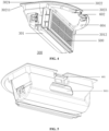
FIG. 4 is a three-dimensional view of a dust box according to some embodiments of the present disclosure. -
FIG. 5 is an oblique view of a dust box according to some embodiments of the present disclosure. -
FIG. 6a - FIG. 6h are schematic diagrams of structure layouts of a top cover according to some embodiments of the present disclosure. -
FIG. 7 is an enlarged schematic diagram of a first positive locking member according to some embodiments of the present disclosure. -
FIG. 8 is an enlarged schematic diagram of a first locking member according to some embodiments of the present disclosure. -
FIG. 9a is an enlarged schematic diagram of a second positive locking member according to some embodiments of the present disclosure. -
FIG. 9b is a schematic diagram of an overall structure of a second positive locking member according to some embodiments of the present disclosure. -
FIG. 9c is an enlarged schematic diagram of a second catcher portion according to some embodiments of the present disclosure. -
FIG. 10 is an enlarged schematic diagram of a second locking member according to some embodiments of the present disclosure. -
FIG. 11 is a three-dimensional structural diagram of a dust box filter from an outside perspective according to some embodiments of the present disclosure. -
FIG. 12 is a three-dimensional structural diagram of a dust box filter from an inner side perspective according to some embodiments of the present disclosure. -
FIG. 13a is a front view of an inner side of a dust box filter according to some embodiments of the present disclosure. -
FIG. 13b is a three-dimensional structural diagram of a filter of a dust box from an inner side perspective according to some embodiments of the present disclosure. -
FIG. 14 is a schematic diagram of an assembly structure of a dust box and a filter according to some embodiments of the present disclosure. -
FIG. 15 is an enlarged schematic diagram of an assembly structure of a dust box and a filter according to some embodiments of the present disclosure. -
FIG. 16 is a schematic diagram of an air intake structure of a protecting cover according to some embodiments of the present application. -
FIG. 17 is a schematic diagram of an air intake structure of a base according to some embodiments of the present application. -
FIG. 18a is a schematic diagram of an internal airflow structure according to some embodiments of the present application. -
FIG. 18b is a schematic diagram of an air intake structure of an exhaust port according to some embodiments of the present application. -
FIG. 19 is an enlarged schematic diagram of an air passage structure according to some embodiments of the present application. -
FIG. 20 is a schematic diagram of a structure of an accommodating chamber according to some embodiments of the present application. -
FIG. 21 is a schematic diagram of a structure of a dust box according to some embodiments of the present application. -
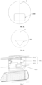
FIG. 22 is a diagram showing a symmetrical structure of an automatic cleaning device along axis BB according to some embodiments of the present application. -
FIG. 23 is a schematic diagram of a structure of a dust collection station according to some embodiments of the present application. -
FIG. 24 is a schematic diagram of a structure of an automatic cleaning system according to some embodiments of the present application. - Moving platform 100, backward portion 110, forward portion 111, sensing system 120, buffer 122, cliff sensor 123, control system 130, driving system 140, driving wheel assembly 141, steering assembly 142, cleaning module 150, dry cleaning module 151, side brush 152, main brush module 153, dust box 300, filter 500, energy system 160, human-computer interaction system 170, wet cleaning assembly 400, accommodating chamber 200, first chamber 201, second chamber 202, dust suction port 203, exhaust port 204, air outlet 208, accommodating portion 301, top cover 302, first opening 3011, second opening 3012, first portion 3021, edge portion 30211, step portion 205, second portion 3022, support structure 3023, groove 2021, first recess 206, second recess 207, first positive locking member 601, second positive locking member 602, first catcher recess 603, first elastic arm 6011, first catcher portion 6012, first snapping-fit portion 6013, first locking member 701, second catcher recess 605, second elastic arm 6021, second catcher portion 6022, second snapping-fit portion 6023, second locking member 702, soft rubber frame 501, soft rubber protrusion 5011, filter element 502, first rib portion 510, anti-mistake protrusion 509, inner sealing lip 507, outer sealing lip 506, step surface 503, magnet mounting hole 504, second rib portion 5041, catcher handle 505, hollow structure 508, third protrusion 5012, elastic structure 5013, blocking portion 5014, first air inlet door 3013, second air inlet door 3014, first side wall 3015, second side wall 3016, protecting cover 1212, position determination apparatus 1211, air passage 209, air inlet hole 20111, third side wall 2011, fourth side wall 2012, spacer 20112, notch 20113, dust collection station 700, dust collection station base 710, dust collection station body 720, dust collection port 711, sealing rubber pad 714.
- For clearer descriptions of the purposes, technical solutions and advantages in the present application, the present application is further described in detail hereinafter in combination with the accompanying drawings. Apparently, the described embodiments are merely some embodiments, rather than all embodiments, of the present application. Based on the embodiments of the present application, all other embodiments derived by a person of ordinary skill in the art without creative efforts shall fall within the protection scope of the present application.
- The terms used in the embodiments of the present application are only for the purpose of describing specific embodiments, but are not intended to limit the present application. The singular forms "a", "the" and "said" used in the embodiments and the appended claims of the present application are intended to include the plural forms as well, unless otherwise clearly specified in the context. "A plurality of" generally includes at least two.
- It should be understood that the term "and/or" used herein only describes an associated relationship of associated objects, indicating three kinds of relationships. For example, A and/or B can represent that A exists alone, A and B exist concurrently, and B exists alone. In addition, the character "/" herein generally indicates that the associated objects are in an "or" relationship.
- It should be understood that although the terms first, second, third, etc. may be used in the embodiments of the present application to describe certain objects, these objects should not be limited by these terms. These terms are merely used for distinguishing. For example, a first object may also be referred to as a second object, and similarly, a second object may also be referred to as a first object, without departing from the scope of the embodiments of the present application.
- It should also be noted that the terms "comprise", "include" or any other variants are intended to cover the nonexclusive containing, such that the commodities or apparatuses including a series of elements not only include those elements, but also include other unclearly listed elements, or also include the inherent elements of such commodities or apparatuses. Without more limitations, the element defined by the phrase "comprising a .." does not exclude the existence of other identical elements in the commodity or apparatus that includes such an element.
- Alternative embodiments of the present application will be described in detail below with reference to the accompanying drawings.
-
FIG. 1 and FIG. 2 are schematic structural diagrams of an automatic cleaning device according to an exemplary embodiment. As shown inFIG. 1 and FIG. 2 , the automatic cleaning device may be a vacuum cleaning robot, a mopping/brushing robot, a window climbing robot, or the like. The automatic cleaning device may include a movingplatform 100, asensing system 120, acontrol system 130, adriving system 140, acleaning module 150, anenergy system 160, and a human-machine interaction system 170. Among them: - The moving
platform 100 may be configured to automatically move on an operation surface in a target direction. The operation surface may be a surface to be cleaned by the automatic cleaning device. In some embodiments, the automatic cleaning device may be a mopping robot, in which case the automatic cleaning device works on a floor, and the floor is the operation surface; the automatic cleaning device may also be a window cleaning robot, in which case the automatic cleaning device works on the exterior surface of glass of a building, and the glass is the operation surface; and the automatic cleaning device may also be a pipeline cleaning robot, in which case the automatic cleaning device works on the interior surface of a pipeline, and the interior surface of the pipeline is the operation surface. Merely for the purpose of illustration, the following description in the present application is illustrated by taking a mopping robot as an example. - In some embodiments, the moving
platform 100 may be an autonomous moving platform or a non-autonomous moving platform. The autonomous moving platform means that the movingplatform 100 itself can automatically and adaptively make operation decisions according to unexpected environmental inputs, while the non-autonomous moving platform itself, instead of adaptively making operation decisions according to unexpected environmental inputs, can execute given programs or run according to certain logic. Correspondingly, in the case that the movingplatform 100 is the autonomous moving platform, the target direction may be autonomously determined by the automatic cleaning device; and in the case that the movingplatform 100 is the non-autonomous moving platform, the target direction may be set systematically or manually. The movingplatform 100 includes aforward portion 111 and abackward portion 110 when the movingplatform 100 is the autonomous moving platform. - The
sensing system 120 includes aposition determination apparatus 121 located above the movingplatform 100, abuffer 122 located on theforward portion 111 of the movingplatform 100, and sensing devices such as acliff sensor 123, an ultrasonic sensor (not shown in the figures), an infrared sensor (not shown in the figures), a magnetometer (not shown in the figures), an accelerometer (not shown in the figures), a gyroscope (not shown in the figures) and an odometer (not shown in the figures), which are located at the bottom of the moving platform for providing various position information and motion state information of the automatic cleaning robot for thecontrol system 130. - For clearer descriptions of the actions of the automatic cleaning device, the following directions are defined as follows. The automatic cleaning device may travel on the floor through various combinations of movements relative to the following three perpendicular axes defined by the moving platform 100: a transverse axis Y, a front-back axis X, and a central vertical axis Z. A forward driving direction along the front-back axis X is marked as "forward", and a backward driving direction along the front-back axis X is marked as "backward". The transversal axis Y extends substantially between a right wheel and a left wheel of the automatic cleaning device along an axis center defined by the center point of a
driving wheel assembly 141, where the automatic cleaning device may rotate about the axis Y. It is called "pitch up" when the forward portion of the automatic cleaning device tilts upwards and the backward portion thereof tilts downwards, and it is called "pitch down" when the forward portion of the automatic cleaning device tilts downwards and the backward portion thereof tilts upwards. In addition, the automatic cleaning device may rotate around the axis Z. In the forward direction of the automatic cleaning device, it is called "turn right" when the automatic cleaning device tilts to the right of the axis X, and it is called "turn left" when the automatic cleaning device tilts to the left of the axis X. - As shown in
FIG. 2 , thecliff sensors 123 are provided at the bottom of the movingplatform 100 and provided in front and rear of thedriving wheel assembly 141. The cliff sensors are configured to prevent the automatic cleaning device from falling off when the automatic cleaning device moves back, so as to protect the automatic cleaning device against damage. The aforementioned "front" refers to the side in the same direction as the travelling direction of the automatic cleaning device, and the aforementioned "rear" refers to the side in a direction opposite to the travelling direction of the automatic cleaning device. - A specific type of the
position determination apparatus 121 includes, but is not limited to, a camera and a laser distance sensor (LDS). - The various components in the
sensing system 120 may work independently or jointly to achieve intended functions more accurately. The surface to be cleaned is identified by thecliff sensor 123 and the ultrasonic sensor to determine the physical properties of the surface to be cleaned, including surface materials, the degree of cleanliness, etc., and more accurate determinations may be performed in combination with the camera, and the laser distance sensor, etc. - For example, it may be determined by the ultrasonic sensor whether the surface to be cleaned is a carpet or not. If the ultrasonic sensor determines that the surface to be cleaned is made of a carpet material, the
control system 130 controls the automatic cleaning device to conduct carpet-mode cleaning. - The
buffer 122 is provided on theforward portion 111 of the movingplatform 100. Thebuffer 122 detects one or more events (or objects) in a travelling path of the automatic cleaning device via the sensing system (for example, an infrared sensor) when thedriving wheel assembly 141 propels the automatic cleaning device to travel on the floor in the process of cleaning. The automatic cleaning device may control, according to the events (or objects), such as an obstacle and a wall, detected by thebuffer 122, thedriving wheel assembly 141 to enable the automatic cleaning device to respond to the events (or objects), for example, moving away from the obstacle. - The
control system 130 is provided on a main circuit board in the movingplatform 100, and includes a computing processor, such as a central processing unit or an application processor, which communicates with non- transitory memories, such as a hard disk, a flash memory and a random access memory. The application processor is configured to receive environmental information sensed by the plurality of sensors and transmitted from thesensing system 120, to draw a simultaneous map of an environment where the automatic cleaning device is located by using a positioning algorithm (for example, SLAM) according to obstacle information fed back by the position determination apparatus, to autonomously determine the travelling path according to the environmental information and the environmental map, and then to control thedriving system 140 to perform operations of moving forwards, moving backwards and/or turning according to the autonomously determined travelling path. Furthermore, thecontrol system 130 may also determine whether to activate thecleaning module 150 to perform a cleaning operation according to the environmental information and the environmental map. - In particular, the
control system 130 may comprehensively determine a current working state (such as crossing a threshold, getting on a carpet, being at a cliff, being stuck from above or below, having a full dust box or being picked up, etc.) of the sweeping robot in combination with distance information and speed information fed back by thebuffer 122, thecliff sensor 123, and the sensing devices such as the ultrasonic sensor, the infrared sensor, the magnetometer, the accelerometer, the gyroscope and the odometer, and may also give a specific next action strategy for different situations, so that the working of the automatic cleaning device is more in line with the requirements of an owner, thus achieving better user experience. Furthermore, the control system may plan the most efficient and reasonable cleaning path and cleaning mode based on the information of the simultaneous map drawn by SLAM, which greatly improves the cleaning efficiency of the automatic cleaning device. - The
driving system 140 may execute a driving command based on a specific distance and angle information, such as components of x, y and θ to control the automatic cleaning device to travel across the floor. As shown inFIG. 2 , thedriving system 140 includes adriving wheel assembly 141, and may control a left wheel and a right wheel simultaneously. In order to control the movement of the automatic cleaning device more accurately, thedriving system 140 preferably includes a left driving wheel assembly and a right driving wheel assembly that are symmetrically provided along a transverse axis defined by the movingplatform 100. - For more stable movement on the floor or higher movement ability of the automatic cleaning device, the automatic cleaning device may include one or
more steering components 142. Thesteering components 142 may be driven wheels or driving wheels, the structure forms of which include but is not limited to universal wheels. Thesteering component 142 may be located in front of thedriving wheel assembly 141. - The
energy system 160 includes a rechargeable battery, such as a nickel-hydrogen battery and a lithium battery. The rechargeable battery may be connected to a charging control circuit, a battery pack charging temperature detecting circuit, and a battery undervoltage monitoring circuit, which are then connected to a single-chip microcomputer control circuit. A host of the automatic cleaning device is connected to a charging pile by a charging electrode provided on a side of or below the body of the automatic cleaning device for charging. - The human-
machine interaction system 170 includes buttons on a panel of the host for a user to select functions, and may further include a display screen and/or an indicator light and/or a speaker, as well as a mobile phone client program. The display screen, the indicator light and the speaker show the current state or function options of the automatic cleaning device to the user. For a route navigation type cleaning device, a mobile phone client may show a map of the environment where the device is located, as well as the location of the device to the user, thus providing the user with richer and more user-friendly function items. - As shown in
FIG. 2 , thecleaning module 150 may include adry cleaning module 151. - The
dry cleaning module 151 includes a roller brush, a dust box, a fan, and an air outlet. The roller brush in a certain interference with the floor sweeps up debris on the floor and rolls up it to the front of a dust suction inlet between the roller brush and the dust box, and then the debris is sucked into the dust box by a gas with a suction force, which is generated by the fan and passes through the dust box. The dust removal capacity of the sweeping robot can be characterized by the dust pickup (DPU) efficiency of the debris, which is affected by the structure and the material of the roller brush, the utilization rate of air in an air passage formed by the dust suction inlet, the dust box, the fan, the air outlet and connecting parts among the dust suction inlet, the dust box, the fan and the air outlet, and affected by the type and the power of the fan; and thus it is a complex problem of system design. The improvement of dust removal capacity is of greater significance to the energy-limited automatic cleaning device than an ordinary plug-in vacuum cleaner. This is because the improvement of the dust removal capacity directly and effectively reduces the demand for energy, i.e., an original cleaning device capable of cleaning 80 square meters of the floor with one charge may be improved to clean 180 square meters or more with one charge. In addition, the service life of a battery with a reduced number of charging times may be greatly prolonged, such that the frequency of replacing the battery by the user may be reduced. More intuitively and importantly, the improvement of the dust removal capacity is the most obvious and important user experience as the user can directly draw a conclusion about whether the thorough sweeping/mopping is achieved. The dry cleaning module may further include aside brush 152 provided with a rotating shaft at a certain angle relative to the floor, for moving the debris into a roller brush area of thecleaning module 150. - As an optional cleaning module, the automatic cleaning device may further include a wet cleaning module configured to clean at least part of the operation surface in a wet cleaning manner. Among them, the wet cleaning module includes a water tank, a cleaning head, a driving unit, or the like. Water from the water tank flows along a waterway to the cleaning head, and the cleaning head cleans at least part of the operation surface under the driving of the driving unit.
- For the layout frame of the shell of the existing automatic cleaning device, the structure is complex, the number of parts is large, the assembly time is long, the process is complicated, and the cost is high. For example, a top cover and a flip mechanism are added to the automatic cleaning device, and an upper shell decorative part is designed on the top cover. Although the upper shell decorative part and the upper cover can cover up the ugliness and protect the internal components, they result in that the structure of the whole machine is complex and the cost is high, and the design space of components such as the dust box under the top cover is affected.
- To this end, embodiments of the present disclosure provides an automatic cleaning device without a flip cover, in which the design space of the dust box and its accommodating chamber is increased, while unnecessary components of the automatic cleaning device are omitted. The same structure produces the same technical effect, and some technical effects are not repeated here. In particular, the present disclosure provides an automatic cleaning device, as shown in
FIG. 3 , which includes a movingplatform 100 configured to move automatically on an operating surface. The movingplatform 100 includes anaccommodating chamber 200. In some embodiments, theaccommodating chamber 200 is provided at a slightly rear side in a forward direction of the automatic cleaning device. Theaccommodating chamber 200 includes afirst chamber 201 and asecond chamber 202. The automatic cleaning device further includes adry cleaning module 151 which includes adust box 300. Thedust box 300 is detachably assembled in theaccommodating chamber 200. Among them, thefirst chamber 201 and thesecond chamber 202 are provided adjacent to each other in sequence in the forward direction of the automatic cleaning device. The depth of thefirst chamber 201 is greater than the depth of thesecond chamber 202. Thefirst chamber 201 and thesecond chamber 202 are provided adjacent to each other in sequence in the forward direction of the automatic cleaning device, so that the part with larger volume and weight in the whole dust box may be provided closer to the middle of the automatic cleaning device, resulting in that the dust box is more stably provided in theaccommodating chamber 200, and the center of gravity of the whole cleaning device is more stable. It is more stable and not easy to overturn during the process of traveling, turning, and crossing obstacles. At the same time, it is convenient to make the dust box accommodating portion and the dust box top cover into an integrated structure, so that the dust box top cover may be used as a part of the top surface of the moving platform, and is flush with other parts of the top surface of the moving platform, omitting the flip cover structure of the traditional cleaning device. At the same time, it is convenient to directly align the dust suction port provided at the approximately central position of the bottom of the cleaning device with the dust box, so that the dust enters the dust box directly from the dust suction port, reducing the distance of dust entering the machine, and avoiding dust pollution to the inside of the machine. The depth of thefirst chamber 201 is greater than the depth of thesecond chamber 202, so that the dust box and the dust box top cover can be accommodated in a separate structure, which is convenient for the integrated design of the dust box top cover. Adust suction port 203 is provided at the bottom of a front side wall of thefirst chamber 201. Anair outlet 208 is provided at a rear side wall where thefirst chamber 201 and thesecond chamber 202 are connected. Theair outlet 208 has a grid structure. The space below thesecond chamber 202 accommodates a fan, which may be carried by a fan bracket. In some embodiments, theair outlet 208 constitutes a part of the fan bracket. Anexhaust port 204 is provided on a rear side wall of the movingplatform 100. Under the action of the fan suction force, the dust enters thedust box 300 via thedust suction port 203, and the airflow is filtered by the dust box filter and discharged from theexhaust port 204. - In some embodiments, the
dust box 300 includes anaccommodating portion 301 and a top cover 302 provided above theaccommodating portion 301. The top cover is fixedly connected to the accommodating portion. The fixed connection method includes but is not limited to bonding, welding, integral molding, bolt connection, snap connection, etc. The accommodating portion is used to accommodate the garbage sucked from thedust suction port 203. The appearance of the accommodating portion is substantially matched with thefirst chamber 201. - A roller brush in a certain interference with the ground sweeps up the garbage on the ground. The garbage is rolled to the front of the
dust suction port 203 between the roller brush and thedust box 300 under the action of a negative pressure airflow generated by the fan, and then is sucked into thedust box 300 by a suction airflow generated by the fan and passing through thedust box 300. The garbage is isolated inside thedust box 300 by afilter 500, and the filtered air enters the fan. - Typically, the
accommodating portion 301 of thedust box 300 is provided with afirst opening 3011 provided at a front side of the dust box. Thefirst opening 3011 is aligned with thedust suction port 203. Theaccommodating portion 301 is provided with asecond opening 3012 provided at a rear side of the dust box. Thefilter 500 is provided at thesecond opening 3012. Thesecond opening 3012 is connected to theair outlet 208. Thefilter 500 is detachably connected to the box body of thedust box 300, which is convenient for the removal and cleaning of the filter. Among them, the front side refers to the side of the X direction along the forward direction of the automatic cleaning device after thedust box 300 is assembled in theaccommodating chamber 200, and the rear side refers to the side of the X direction opposite to the forward direction of the automatic cleaning device. - In some embodiments, the top cover 302 includes a
first portion 3021 covering theaccommodating portion 301 and asecond portion 3022 extending outwards beyond theaccommodating portion 301. When thedust box 300 is assembled in theaccommodating chamber 200, theaccommodating portion 301 and thefirst portion 3021 of the top cover 302 are accommodated in thefirst chamber 201, and thesecond portion 3022 of the top cover 302 is accommodated in thesecond chamber 202. The top cover 302 and the top part of the first chamber and the structure of the second chamber are substantially matched with each other, so that thedust box 300 may be stably installed in theaccommodating chamber 200, avoiding the shaking of the dust box due to the bumps during the movement of the automatic cleaning device. At the same time, the dust box top cover can exactly cover the accommodating portion and the position of the fan, so that the upper surface of the dust box top cover is substantially level with the upper surface of the moving platform, ensuring the flatness of the outer surface of the automatic cleaning device, and the overall coordination of the appearance is better. It also provides more space options for the design of various components under the top cover including the accommodating portion, which facilitates the arrangement of the positions of different components. The volume of the dust box may be selectively increased, and the specific size may be provided as needed without affecting the overall opening size of the accommodating chamber, thus reducing the mold opening cost. - In some embodiments, the
first portion 3021 of the top cover 302 includes anedge portion 30211 that protrudes from the edge contour of the accommodating portion and extends outwards. Theaccommodating chamber 200 includes astep portion 205 extending around the top edge of the accommodating chamber. Thestep portion 205 is configured to accommodate at least a portion of theedge portion 30211 and at least a portion of the outer edge of the second portion, so that the upper surface of the top cover is substantially coplanar with the upper surface of the moving platform. Thestep portion 205 of theaccommodating chamber 200 extending around the top edge of theaccommodating chamber 200 can completely accommodate the edge of the top cover 302, so that the top cover 302 may be basically tightly accommodated in theaccommodating chamber 200, which can prevent foreign objects from falling directly into the edge gap of the dust box, further preventing the dust box from getting stuck, and at the same time ensuring the aesthetic appearance of the top cover as the upper surface of the automatic cleaning device. - In some embodiments, a
support structure 3023 is provided below thesecond portion 3022 of the top cover 302, and configured to support thesecond portion 3022 of the top cover. Alternatively, thesupport structure 3023 is integrally formed with at least a portion of theaccommodating portion 301 to enhance the support force of thesupport structure 3023 on thesecond portion 3022 of the top cover 302, effectively preventing damage to thesecond portion 3022. Thesupport structure 3023 may include, but is not limited to, an arc-shaped structure and a linear structure. As an implementation, for example, thesupport structure 3023 is two symmetrically provided arc-shaped structures that substantially match the outer edge contour of thesecond portion 3022 of the top cover 302. - In some embodiments, the lower surface of the
second chamber 202 includes agroove 2021. Thegroove 2021 substantially matches with the contour of thesupport structure 3023, and is configured such that when the second portion of the top cover is accommodated in the second chamber, thesupport structure 3023 is accommodated in thegroove 2021, so that the upper surface of the top cover 302 is basically horizontal. - In some embodiments, the top cover is symmetrically provided along the central axis of the forward direction of the automatic cleaning device. In some embodiments, the top cover has at least one or a combination of the following shapes: D shape, rectangular, square, circular, elliptical, triangular, quadrilateral, pentagon, hexagon, heptagon or octagon, as shown in
FIG. 6a -FIG. 6h . The symmetrical arrangement can make the appearance of the machine more beautiful without the cover, and it is more convenient for the installation and removal of the dust box. - In some embodiments, the
first chamber 201 includes afirst locking member 701. Thesecond chamber 202 includes a second locking member 72. Thefirst portion 3021 of the top cover includes a firstpositive locking member 601. Thesecond portion 3022 of the top cover includes a second positive lockingmember 602. The firstpositive locking member 601 cooperates with thefirst locking member 701 to achieve locking. The second positive lockingmember 602 cooperates with the second locking member 72 to achieve locking. - The above-mentioned embodiments relate to a dust box of an automatic cleaning device and its mounting structure. An accommodating chamber is provided on a rear side of a forward direction of the automatic cleaning device. The accommodating chamber includes a first chamber and a second chamber. The depth of the first chamber is greater than the depth of the second chamber. When the dust box is assembled in the accommodating chamber, the upper surface of the dust box top cover is substantially coplanar with the upper surface of the moving platform, thus simplifying the structure of the top surface of the automatic cleaning device, reducing the production cost, and increasing the design space of the accommodating chamber.
- The existing automatic cleaning device is provided with a pop-up dust box or a non-pop-up dust box. The pop-up dust box is provided with a top cover and a flip mechanism. When taking and placing the dust box, the top cover needs to be opened, and then the dust box is ejected by pressing the dust box. This implementation requires a complex dust box ejection mechanism, which includes a plurality of parts such as springs. Due to repeated use of the spring, the elasticity decreases, making it impossible for the dust box to pop up smoothly. In addition, many other parts and components can easily cause the dust box to not pop up normally, affecting its use. The non-pop-up dust boxes often adopts a complex locking structure, in which the spring assembly is prone to aging and damage, and the pressing component is not comfortable enough to match the finger during operation, resulting in a poor overall user experience.
- To this end, embodiments of the present disclosure provides an automatic cleaning device without a flip cover, which facilitates the smooth placement of the dust box, while unnecessary components of the automatic cleaning device are omitted. Compared with the above embodiment, this embodiment briefly describes some structural features. The same structure has the same technical effect, and some technical effects are not repeated here. In particular, as shown in
FIG. 1- FIG. 5 andFIG. 7 , an automatic cleaning device includes: a movingplatform 100, configured to automatically move on an operating surface and including anaccommodating chamber 200 provided on a rear side in a forward direction; and a cleaning module, including adust box 300. Thedust box 300 is detachably assembled in theaccommodating chamber 200; and the dust box includes anaccommodating portion 301, a top cover 302 provided above the accommodating portion, and a locking mechanism. The locking mechanism includes a first locking mechanism 610 substantially provided at a central axis of the top cover. Among them, the first locking mechanism 610 includes at least afirst catcher recess 603 and a firstpositive locking member 601. The firstpositive locking member 601 is provided in thefirst catcher recess 603. The firstpositive locking member 601 can elastically move relative to thefirst catcher recess 603 under the action of an external force. Thefirst catcher recess 603 is formed downwards along an edge of a first portion of the top cover. Thefirst catcher recess 603 provides a sufficient depth in the Z direction so that the height of the firstpositive locking member 601 is lower than the surface of the top cover. Thefirst catcher recess 603 provides a sufficient elastic space in the X direction so that when the firstpositive locking member 601 elastically moves inwards, there is sufficient activity space. - In some embodiments, the first
positive locking member 601 includes a firstelastic arm 6011, afirst catcher portion 6012 and a first snapping-fit portion 6013. The firstelastic arm 6011 extends upwards from the bottom of thefirst catcher recess 603. Thefirst catcher portion 6012 is provided at an end of the firstelastic arm 6011 that extends upwards. The first snapping-fit portion 6013 extends laterally along the firstelastic arm 6011. The firstelastic arm 6011 is generally in the shape ofto reduce materials and increase elasticity, and this shape and structure are not limited. The
first catcher portion 6012 is laterally provided above the firstelastic arm 6011. Thefirst catcher portion 6012 includes a bottom surface that protrudes generally outwards and a catcher surface that extends upwards along the bottom surface. The catcher surface extends to a position that is generally flush with the top cover. The catcher surface may be an arc structure, that is, its projection on the horizontal plane is an arc. The catcher surface is convenient for receiving manual operation, and is more in line with the force relationship of ergonomics with the finger shape. In some embodiments, the first snapping-fit portion 6013 is a pair of sheet-like structures symmetrically provided along two sides of the firstelastic arm 6011. The width of the sheet-like structure decreases from a root to a free end, so as to facilitate smooth insertion of thefirst locking member 701. The firstelastic arm 6011 may be made of common elastic materials, such as plastic or organic elastic materials. - In some embodiments, as shown in
FIG. 8, FIG. 8 is an enlarged schematic diagram of the first locking member at position A inFIG. 3a . Thefirst locking member 701 is provided on an inner wall of theaccommodating chamber 200 at a position substantially corresponding to the firstpositive locking member 601. The firstpositive locking member 601 cooperates with thefirst locking member 701 to achieve locking. In some embodiments, thefirst locking member 701 is a pair of through holes. The free end of the sheet-like structure is inserted into the through hole to achieve locking. - In some embodiments, a
first recess 206 is provided on the inner wall of the accommodating chamber at a position substantially corresponding to thefirst catcher recess 603. The pair of through holes are provided on two sides of thefirst recess 206. When the firstpositive locking member 601 is inserted into the through hole, locking is achieved. When a finger is inserted into thefirst recess 206 to apply a force to pull the firstpositive locking member 601 out of the through hole, unlocking is achieved. The coordinated cooperation between thefirst recess 206 and thefirst catcher recess 603 makes the insertion operation of the finger easier and more convenient. - In some embodiments, as shown in
FIG. 9a , the locking mechanism further includes asecond locking mechanism 620. Thesecond locking mechanism 620 includes asecond catcher recess 605 and a second positive lockingmember 602. Thesecond catcher recess 605 forms a notch inwardly along the approximate midline position of thesecond portion 3022 of the top cover, such as an arc-shaped or square notch, to facilitate the insertion of a finger for snapping-fit operations. The second positive lockingmember 602 is provided on the lower side of thesecond catcher recess 605. Thesecond catcher recess 605 provides sufficient space for a finger to control the second positive lockingmember 602. The second positive lockingmember 602 elastically moves inwards under action of an external force. In particular, the second positive lockingmember 602 includes a secondelastic arm 6021, asecond catcher portion 6022 and a second snapping-fit portion 6023. Among them, the secondelastic arm 6021 is provided below thesecond catcher recess 605. The secondelastic arm 6021 includes two symmetrical parts. Each of the secondelastic arms 6021 first extends along an opening direction of thesecond catcher recess 605, then extends along an edge direction of the top cover, and then extends along an edge direction of thesecond catcher recess 605. Among them, the opening direction of thesecond catcher recess 605 is as shown inFIG. 9a , which is the A direction from the center of the top cover to the outside; and in this embodiment, it is also the rear direction of the dust box top cover. The two parts of the secondelastic arm 6021 are symmetrically connected substantially as two structures in the shape of IL. Thesecond catcher portion 6022 connects the two parts of the secondelastic arms 6021 that are symmetrically provided. In particular, thesecond catcher portion 6022 is provided above the two second elastic arms, as shown inFIG. 9b and FIG. 9c. FIG. 9c is an enlarged view of the second catcher portion at position C inFIG. 9b . The bottom of thesecond catcher portion 6022 includes abottom surface 60221 that protrudes generally outwards and ancatcher surface 60222 that extends upwards along the bottom surface. The catcher surface extends to a position that is generally flush with the top cover. The catcher surface may be an arc-shaped structure, which is convenient for receiving manual operation and for fingers to apply force. Alternatively, thesecond catcher portion 6022 is integrally formed with the symmetrically provided secondelastic arms 6021. The second snapping-fit portion 6023 is provided on the lateral extension portion of the second elastic arm. The second snapping-fit portion 6023 is a pair of portions symmetrically provided along two sides of the secondelastic arm 6021, for example, protrusions or sheet-like structures extending along the A direction. As an optional implementation, each of the second snapping-fit portions 6023 includes a groove extending inwards from the end of the second snapping-fit portion 6023. The groove can prevent the entire second snapping-fit portion from being deformed too much after being formed and cooled, causing snapping-fit difficulties. Alternatively, the second positive lockingmember 602 further includes a symmetrically provided connectingmember 6024. The connectingmember 6024 is substantially planar. One end of the secondelastic arm 6021 is connected to one side of the connectingmember 6024. The other side of the connectingmember 6024 is connected and fixed to the end face of the support structure. Thesecond catcher portion 6022 exposes thesecond catcher recess 605 in the X direction, so that when unlocking, a finger may be inserted into thesecond catcher recess 605 and press on thesecond catcher portion 6022, applying force to the inside of the dust box along the X axis and driving the second snapping-fit portion 6023 to elastically contract inwards, so that the second snapping-fit portion 6023 pops out from the bottom of thesecond locking member 702 to achieve unlocking. The secondelastic arm 6021 may be made of common elastic materials, such as plastic or organic elastic materials. - In some embodiments, as shown in
FIG. 10, FIG. 10 is an enlarged view of thesecond locking member 702 shown at position B inFIG. 3b . Thesecond locking member 702 is provided on the inner wall of theaccommodating chamber 200 at a position substantially corresponding to the second positive lockingmember 602. The second positive locking member cooperates with the second locking member to achieve locking. The second locking member is a pair of protrusions. The second snapping-fit portion 6023 extends onto the bottom of thesecond locking member 702 to achieve locking. The protrusion may be flat, cylindrical, rectangular, etc., which is not limited, as long as it can lock the second snapping-fit portion. - In some embodiments, a
second recess 207 is provided on the lower surface of thesecond chamber 202 at a position substantially corresponding to thesecond catcher recess 605. The pair of protrusions are provided on the rear side wall of thesecond chamber 202 in the same height, and above thesecond recess 207. Thesecond recess 207 is configured to avoid and accommodate the second positive lockingmember 602 when thedust box 300 is placed in theaccommodating chamber 200, so that the entire dust box may be better placed in place in theaccommodating chamber 200. - In some embodiments, the top cover includes a first portion covering the accommodating portion and a second portion protruding from the accommodating portion and extending outwards. The
second catcher recess 605 and the second positive lockingmember 602 are provided in the second portion of the top cover. The second portion of the top cover includes asupport structure 3023 on the lower part, which is configured to support the second portion of the top cover. The second positive lockingmember 602 is provided on thesupport structure 3023. As shown inFIG. 4 , the symmetrically providedsupport structures 3023 form a space compressed inwards in the X direction. When the secondelastic arm 6021 is connected to thesymmetrical support structure 3023, there is enough elastic space to respond to the applied inward force. - For the locking structure of the dust box described in the above embodiment, locking structures are symmetrically provided in the front and rear directions of the top cover of the dust box, so that when a single hand applies a force to the two elastic structures in front and back of the dust box, unlocking may be achieved, and the dust box will not tilt due to the dust box being ejected from one side after only one side is unlocked. At the same time, due to the simple elastic structure, elastic unlocking may be achieved by only using elastic materials to form elastic arms, avoiding the risk of damage to complex unlocking devices such as springs.
- In some embodiments, as shown in
FIG. 4 , thesecond locking mechanism 620 includes at least one firstmagnetic module 604. The firstmagnetic module 604 is provided between the second portion of the top cover and the supporting structure. As shown inFIG. 3a , the accommodating chamber includes at least one secondmagnetic module 606, which is configured to cooperate with the firstmagnetic module 604 to achieve locking after being magnetized. During an application process, the firstpositive locking member 601 and thesecond catcher recess 605 may be pushed back by a hand to retract the firstpositive locking member 601 corresponding to the dust box. When the dust box is placed in the accommodating chamber and the hand is released, the first snapping-fit portion 6013 on the firstpositive locking member 601 will automatically pop out and is inserted into thefirst locking member 701, and the firstmagnetic module 604 and the secondmagnetic module 606 are magnetized to each other, thus realizing the locking of the dust box. The locking structure is simple and easy to operate, which facilitates the locking of the dust box. - In some embodiments, the
second locking mechanism 620 described above may be an implementation including thesecond catcher recess 605 and the second positive lockingmember 602, or an implementation including the firstmagnetic module 604, or an implementation including both of the above, which is not limited. - The existing automatic cleaning device needs to be equipped with a dust box including a replaceable dust box filter. The traditional filter is generally made of a hard frame made of plastic or metal. The stacked filter element is placed in the frame, and the frame and the filter element are connected and sealed by glue peripherally. Then, a sealing strip is pasted on the frame to seal the gap between the filter and the dust box. Therefore, in the traditional filter part of the dust box, the is complex, the installation steps of the filter are cumbersome, and it wastes labor and costs. In addition, the glue used for sealing is not economical and environmentally friendly.
- To this end, embodiments of the present disclosure provide an automatic cleaning device. The automatic cleaning device includes: a moving platform, configured to automatically move on an operating surface and including an accommodating chamber; and a cleaning module, including a dust box. The dust box is detachably mounted in the accommodating chamber, the dust box includes a dust box filter, the dust box filter is applied to the dust box of the automatic cleaning device, simplifying the assembly process of the dust box filter. This embodiment briefly describes some structural features compared to the above-mentioned embodiments. The same structure produces the same technical effect, and some technical effects are not repeated here. In particular, as shown in
FIG. 11- FIG. 12 , thedust box filter 500 includes: asoft rubber frame 501, the soft rubber frame including at least onesoft rubber protrusion 5011 used to seal the assembly gap with the dust box during the assembly process; and afilter element 502, sleeved in thesoft rubber frame 501. Among them, thesoft rubber frame 501 is non-detachably connected to thefilter element 502. In particular, the non-detachable connection process between thesoft rubber frame 501 and thefilter element 502 may adopt a plastic injection molding process, in which the filter element is sleeved in the frame in advance, and then the soft rubber is applied to the sleeved frame assembly to integrally form a plurality of required sealing protrusions. Alternatively, a double-shot process may be used to first inject the hard rubber frame body, and then the filter element is mounted on the frame body, and then the soft rubber is injected to form the inner and outer sealing protrusions. - The soft rubber frame may be a rectangular, square, oval, circular, polygonal or other structure, and this structure is not limited. In some embodiments, the soft rubber frame is a rectangular structure. The soft rubber frame of the rectangular structure includes two
first side walls 50111 and twosecond side walls 50113 provided opposite to each other. The soft rubber protrusions include afirst protrusion 5011 distributed on the outer peripheral surface of one of thefirst side walls 50111 and asecond protrusion 5015 distributed on the outer peripheral surface of the otherfirst side wall 50111. A pair offirst side walls 50111 and a pair ofsecond side walls 50113 form a rectangular structure frame, and a filter element is sleeved inside the frame of rectangular structure, as shown inFIG. 11 and FIG. 12 . - In some embodiments, the
first protrusion 5011 and thesecond protrusion 5015 may be continuous protrusion structures. For example, thefirst protrusion 5011 and thesecond protrusion 5015 extend continuously from one end of the outer peripheral surface of thefirst side wall 50111 to the other end. Since thefirst protrusion 5011 and thesecond protrusion 5015 are soft rubber structures, when the dust box filter is assembled on the dust box, thefirst protrusion 5011 and thesecond protrusion 5015 will be squeezed and directly sealed between thedust box filter 500 and thesecond opening 3012 of the dust box, and fully contact and seal with the inner wall of thesecond opening 3012 of the dust box extending substantially in the horizontal direction, replacing the traditional step of sealing with a sealing strip after the dust box filter is assembled on the dust box. - In some embodiments, as shown in
FIG. 14 , at least one of the first protrusion and the second protrusion is an inverted structure. The inverted structure is configured to seal the gap between the soft rubber frame and the dust box assembly while preventing the dust box filter from falling off the dust box. In particular, the inverted structure is an arc structure. The arc structure is inclined to the side opposite to the assembly direction of the dust box filter. The inverted structure facilitates the dust box filter to tilt to the side opposite to the assembly direction during the dust box filter assembly process due to the friction force caused as the dust box filter extends into the assembly opening of the dust box, and then be squeezed and sealed between the dust box filter and the dust box. - In some embodiments, the second side wall of the soft rubber frame further includes at least one
third protrusion 5012. Thethird protrusion 5012 is distributed on the outer peripheral surface of at least onesecond side wall 50113 of the frame structure. Thethird protrusion 5012 may be a structure of a plurality of discrete protrusion. As an embodiment, thethird protrusion 5012 is distributed on the outer peripheral surfaces of the twosecond side walls 50113 of the frame structure. When the dust box filter is assembled on the dust box, thethird protrusion 5012 provided on the outer peripheral surface of onesecond side wall 50113 of the frame structure has a slightly longer structure, which may be extended into the recess of the dust box side wall, and plays the role of snapping-fit and preventing the dust box filter from falling off. At the same time, when assembling the dust box filter, the slightly longerthird protrusion 5012 may be first extended into the recess of the dust box side wall, and then the other side of the dust box filter may be installed into the dust box after rotating about thethird protrusion 5012. Thethird protrusion 5012 distributed on the outer peripheral surface of anothersecond side wall 50113 of the frame structure has a smoother structure. When the dust box filter is assembled on the dust box, thethird protrusion 5012 on this side is interference-locked with theelastic structure 5013 of the dust box side wall to prevent the dust box filter from falling off. Among them, theelastic structure 5013 is generally an S structure, which has an inner concave portion for accommodating thethird protrusion 5012 and an outer convex portion locked with thethird protrusion 5012. The outer convex portion may be elastically moved under the action of an external force and locked with thethird protrusion 5012. As shown inFIG. 15 , it is a top diagram of the installation structure of the dust box filter viewed from the bottom of the dust box. In some embodiments, as shown inFIG. 13a and FIG. 13b , the soft rubber frame further includes afirst rib portion 510, which is provided on the outer peripheral surface of the second side wall and is configured to prevent the dust box filter from being installed too deep or too shallow into the dust box, avoiding the poor assembly. During the process of installing the dust box filter into the dust box, when the dust box filter is assembled in place, thefirst rib portion 510 will abut against a blockingportion 5014 provided at the corresponding position of the dust box frame, preventing the filter from extending further inward, thus preventing the dust box filter from being installed too deep into the dust box. At the same time, if thefirst rib portion 510 does not abut against the blockingportion 5014 of the dust box frame during the assembly process, it is considered that the dust box filter is not assembled in place, thus preventing the dust box filter from being installed too shallowly into the dust box, as shown inFIG. 15 . - In some embodiments, as shown in
FIG. 13a and FIG. 13b , the soft rubber frame further includes ananti-mistake protrusion 509, which is provided on the outer peripheral surface of the second side wall, and is configured to prevent the dust box filter from being installed upside down. A recess is provided at the position of the dust box corresponding to theanti-mistake protrusion 509. When the dust box filter is normally installed, theanti-mistake protrusion 509 will enter the recess so that the dust box filter may be normally assembled. When the dust box filter is installed upside down, since there is no such a recess on the other side of the dust box, theanti-mistake protrusion 509 will prevent the dust box filter from being assembled, thus playing an anti-mistake effect of prompting that the dust box filter is installed upside down. - In some embodiments, as shown in
FIG. 3a and FIG. 3b , theaccommodating chamber 200 includes afirst chamber 201 and asecond chamber 202. Thefirst chamber 201 and thesecond chamber 202 are provided adjacent to each other in sequence in the forward direction of the automatic cleaning device. The depth of thefirst chamber 201 is greater than the depth of thesecond chamber 202. Adust suction port 203 is provided at the bottom of the front side wall of thefirst chamber 201. Anair outlet 208 is provided at the rear side wall where thefirst chamber 201 and thesecond chamber 202 are connected. A fan is accommodated in the space below thesecond chamber 202. Anexhaust port 204 is provided at the rear side wall of the movingplatform 100. Under the action of the fan suction force, the dust enters thedust box 300 from thedust suction port 203, and the airflow is discharged from theexhaust port 204 after being filtered by the dust box filter. Theair outlet 208 is provided with a grid structure. - As shown in
FIG. 11 and FIG. 12 , the soft rubber frame further includes aninner sealing lip 507 and anouter sealing lip 506. Theinner sealing lip 507 is provided on thefirst end surface 50116 of thesoft rubber frame 501 around thefilter element 502, and is configured to achieve a sealed fit between the dust box filter and theassembly surface 30121 of thesecond opening 3012 of the dust box. Theassembly surface 30121 of thesecond opening 3012 of the dust box is formed on one side of the second opening close to the inner wall of the dust box, and is a substantially planar structure, which is used to assemble the soft rubber frame after abutting against thefirst end surface 50116 of thesoft rubber frame 501, as shown inFIG. 14 . Theouter sealing lip 506 is provided on thesecond end surface 50115 of thesoft rubber frame 501 around thefilter element 502, and is configured to seal the dust box filter and the edge of theair outlet 208 of theaccommodating chamber 200. Theinner sealing lip 507 and theouter sealing lip 506 are higher than thefirst end face 50116 or thesecond end face 50115 where they are provided. After being assembled in place, theinner sealing lip 507 will be squeezed between the dust box filter and the assembly surface of the dust box. Since theinner sealing lip 507 is made of a flexible material, the assembly surface of the dust box filter and the dust box is sealed under the action of the extrusion force. When the dust box is assembled on the automatic cleaning device, theouter sealing lip 506 of the dust box filter will be squeezed between the dust box filter and the outer side of the grid of theair outlet 208 of theaccommodating chamber 200, thus sealing the assembly surface between the dust box filter and the fan bracket. As shown inFIG. 3a and FIG. 3b , the side wall connecting thefirst chamber 201 and thesecond chamber 202 constitutes the assembly surface of the fan bracket. The fan is provided below thesecond chamber 202. The grid-type air outlet 208 is provided on the side wall connecting thefirst chamber 201 and thesecond chamber 202. By providing theinner sealing lip 507 and theouter sealing lip 506 on thesoft rubber frame 501, the inner end face of thedust box filter 500 and the assembly surface of the dust box air outlet, as well as the outer end face of thedust box filter 500 and the outer surface of the air outlet grid of theaccommodating chamber 200 are sealed and mated, thus omitting the cumbersome step of adding sealing strips inside and outside the traditional dust box filter to meet the air path sealing requirements. In addition, thesoft rubber frame 501 serves as a carrier, and theinner sealing lip 507 and theouter sealing lip 506, which also have a certain flexibility, serve as a sealing structure, so that the contact seal is more closely matched, the fit is more complete, and the sealing effect is stronger, thus ensuring the airtightness of the entire air path and providing a better guarantee for the dust suction and dust exhaust functions of the cleaning device that rely on negative pressure. - In some embodiments, as shown in
FIG. 11 and FIG. 12 , the soft rubber frame further includes astep surface 503 extending outwardly along thesecond end surface 50115 of thesoft rubber frame 501, so that thestep surface 503 and the side wall of thesoft rubber frame 501 form a step structure, which is configured to prevent the dust box filter from being installed too deep into the dust box. During the assembly process, when the dust box filter is extended into the dust box assembly opening, thestep surface 503 will abut against the outer edge of the dust box assembly, thus being stuck at the outer edge of the dust box, and preventing the dust box filter from being installed too deep into the dust box, as shown inFIG. 14 . - In some embodiments, as shown in
FIG. 11 , the soft rubber frame further includes a magneticelement mounting hole 504, which is provided on thesecond end surface 50115 of thesoft rubber frame 501 and is configured to accommodate a magnetic element to ensure that the dust box filter is installed in place. The magnetic element may be a magnet or other electromagnetic component. The magneticelement mounting hole 504 is used for installing an inductive magnetic element. The magneticelement mounting hole 504 has a sufficient depth to ensure that the magnetic element may be installed in a fixed position on the inside of the filter. When the entire filter is installed in a fixed position, it may be detected by a Hall sensor to ensure that the filter is installed in place. - In some embodiments, as shown in
FIG. 11 , the soft rubber frame further includes asecond rib portion 5041, which is provided around the periphery of the magnetic element mounting hole and is configured to prevent liquid from entering the magnetic element mounting hole. Thesecond rib portion 5041 tightly wraps the outer end of the magnetic element outside the magneticelement mounting hole 504 to prevent the magnetic element from rusting and failing. Thesecond rib portion 5041 may be a soft rubber material, which further wraps the magnetic element after being squeezed. - In some embodiments, as shown in
FIG. 11 , the soft rubber frame further includes acatcher handle 505, which is provided at a position extending outward from thestep surface 503 and is configured to facilitate the removal of the dust box filter. The shape and structure of the catcher handle 505 are not limited and may be semicircular, square, rectangular, etc. - In some embodiments, as shown in
FIG. 12 , the soft rubber frame further includes ahollow structure 508, which is provided on the first side wall and/or the second side wall of the frame, and is configured to reduce the overall weight of the frame. Thehollow structure 508 may be a plurality of blind holes recessed inwardly. The structure of the blind holes is not limited and may be circular, square, rectangular, irregular, etc. - In the automatic cleaning device described in the above embodiments, the dust box filter, due to the adoption of a soft rubber frame design, may be directly squeezed and assembled in the dust box opening during the assembly process, and at the same time cooperates with the first protrusion, the inner sealing lip and the outer sealing lip and other structures, so that the filter and the assembly surface can achieve a tight sealing effect during assembly, avoiding the manual assembly part of the traditional process of inserting the filter and then gluing and bonding, simplifying the process, reducing the number of assembly parts, and reducing the cost at the same time, and there is no glue bonding, no odor, and it is more environmentally friendly.
- In some embodiments, as shown in
FIG. 14 , this embodiment further provides a dust box, including a dust box filter as described in any of the above embodiments. The structure of the dust box is as described in the above embodiments, and will not be repeated here. - In some embodiments, there is further provided an automatic cleaning device, including a dust box as described in any of the above embodiments. The structure of the automatic cleaning device is as described in the above embodiments, and will not be repeated here.
- After the automatic cleaning device finishes dust absorption, it can enter the dust collection station for automatic dust collection. When the automatic cleaning device is automatically collecting the dust, since the air path entering the automatic cleaning device is single and the air path is blocked by the machine structure and is not smooth enough, it is difficult for the dust collection station to suck all the garbage in the dust box into the garbage bag of the dust collection station. In order to clean the garbage in the dust box as much as possible, it is often necessary to increase the power of the dust collection station fan, which brings greater noise and more energy consumption.
- To this end, an embodiment of the present application further provides an automatic cleaning device with a dust collection function. By improving the air path structure of the automatic cleaning device, the airflow can more easily enter the dust box during the dust collection process of the automatic cleaning device, so that it is easier to clean the garbage in the dust box. Compared with the above embodiment, this embodiment briefly describes some structural features. The same structure produces the same technical effect, and some technical effects are not repeated here. Specifically, according to the specific implementation of the present application, the present application provides an automatic cleaning device with a dust collection function, which includes a moving
platform 100. The movingplatform 100 is configured to automatically move on an operating surface. The movingplatform 100 generally includes an upper shell, a lower shell and a side shell that form the appearance of the automatic cleaning device, as well as structures and accessories provided in the internal space of the aforementioned shells. Specifically, the movingplatform 100 includes anaccommodating chamber 200 and adriving wheel assembly 141. Theaccommodating chamber 200 is substantially located in the rear half portion in the forward direction of the moving platform. Theaccommodating chamber 200 is formed in the form of an inward recess. As described above, thedriving wheel assembly 141 is located on the lower shell of the movingplatform 100 to provide power for the automatic cleaning device to move forward. The movingplatform 100 further includes acleaning module 150, which includes adust box 300 and amain brush module 153. Thedust box 300 is detachably mounted in theaccommodating chamber 200. A part of the structure of thedust box 300 is as described in the above embodiment and will not be described in detail herein. Thedust box 300 further includes a firstair inlet door 3013 and a secondair inlet door 3014. The firstair inlet door 3013 and the secondair inlet door 3014 are respectively located on afirst side wall 3015 and asecond side wall 3016 of the dust box. The firstair inlet door 3013 and the secondair inlet door 3014 are configured to provide two intake airflows in different directions during dust collection, which is beneficial to forming an airflow vortex in the dust box during dust collection, greatly reducing the garbage residue in the dust box, reducing airflow dead angles, and improving the dust collection rate. The provision of the double air inlet doors also increases the air intake rate and improves the efficiency of forming the airflow vortex. Among them, the source of the intake airflows includes at least one of the following: airflow I entering from the top gap of the movingplatform 100, airflow II entering from the gap of themain brush module 153, airflow III entering from the rear side wall of the moving platform, and airflow IV entering from the gap of thedriving wheel assembly 141. By providing a plurality of groups of intake airflows, the air intake volume and air intake speed of the automatic cleaning device are increased, thus increasing the dust collection strength and efficiency of the dust collection station, further reducing the airflow dead angle in the dust box, reducing garbage residue, and improving the dust collection rate. - When the automatic cleaning device finishes dust absorption and returns to the dust collection station for dust collection, the fan at the dust collection station will start to suck the garbage in the dust box. During the suction process, the airflow enters the dust box through a plurality of channels via the first
air inlet door 3013 and the secondair inlet door 3014, and then is sucked out from the dust collection port by the dust collection station along with the garbage. In the dust collection state, the main cleaning brush of the automatic cleaning device moves in the opposite direction as the fan at the dust collection station starts. The automatic cleaning device is in a "dust-spitting" state. The airflow enters the inner cavity of the dust box from the outside of the automatic cleaning device through the gap between the shells of the automatic cleaning device. The airflow forms a vortex in the inner cavity of the dust box, rotating and throwing up the garbage in the inner cavity of the dust box. The dust collection fan of the dust collection station starts, communicates to the main brush, thefirst opening 3011 of the dust box, and the inner cavity of the dust box through a certain airway, and then relies on suction to suck the garbage in the inner cavity of the dust box into the garbage collection container or bag inside the dust collection station. - Among them, the airflow entering the dust box mainly includes the airflow I entering from the top gap of the moving
platform 100, as shown inFIG. 16 . Specifically, the airflow I entering from the top gap of the movingplatform 100 includes the airflow entering from the gap between the protectingcover 1212 and the top surface of the movingplatform 100, and the airflow entering from the gap between the protectingcover 1212 and theposition determination apparatus 1211. In the present disclosure, when the protectingcover 1212 and theposition determination apparatus 1211 are assembled, airflow gaps may be formed between the protectingcover 1212 and the top surface of the movingplatform 100 and between the protectingcover 1212 and theposition determination apparatus 1211 by means of support structures such as protrusions. With the adsorption of the fan at the dust collection station, a negative pressure is formed in thedust box 300 in fluid communication with the fan at the dust collection station. The firstair inlet door 3013 and the secondair inlet door 3014 are opened into the dust box to guide the airflow outside the dust box to enter. A negative pressure is also formed in the moving platform, which will naturally guide the air outside the moving platform to enter the machine through the airflow gap formed between the protectingcover 1212 and the top surface of the movingplatform 100 and the protectingcover 1212 and theposition determination apparatus 1211. Compared with the traditional sealing structure, the airflow gaps formed between the protectingcover 1212 and the top surface of the movingplatform 100 and between the protectingcover 1212 and theposition determination apparatus 1211 can add more airflow channels, thus ensuring sufficient airflow entering the dust box, further improving the air intake volume and air intake speed of the dust box, thus increasing the dust collection strength and dust collection efficiency of the dust collection station, and reducing the airflow dead angle in the dust box, reducing garbage residue, and improving the dust collection rate. More importantly, guiding the airflow to pass near theposition determination apparatus 1211 helps to take away the excess heat generated by the position determination apparatus during the working process, plays a cooling role, is conducive to improving the operation stability of the position determination device, and prolonging the life of electronic devices. In addition, the top airflow is cleaner than other parts, and is safer and more friendly to the internal air path of the machine. - The airflow entering the dust box further includes airflow II entering from the gap of the
main brush module 153. As shown inFIG. 17 , airflow II enters the shell from the assembly gap of themain brush module 153 on the bottom surface of the lower shell of the movingplatform 100. Among them, when the device is assembled, the edge gap of themain brush module 153 and the edge gap of thedriving wheel assembly 141 are formed through the protrusions or grooves or the inherent assembly gaps. As the fan at the dust collection station is adsorbing, a negative pressure is formed in the moving platform, which will naturally guide the air outside the moving platform to enter the machine from the edge gap of themain brush module 153. Compared with the traditional sealing structure, the edge gap of themain brush module 153 can add more airflow channels, thus ensuring that sufficient airflow enters the dust box, further improving the air intake volume and air intake speed of the dust box, thus increasing the dust collection strength and dust collection efficiency of the dust collection station, and at the same time reducing the airflow dead angle in the dust box, reducing garbage residue, and improving the dust collection rate. In addition, the distance for airflow II to reach the two air inlet doors of the dust box is shorter, and the air passage is smoother, which is conducive to further improving the airflow replenishment speed and ensuring the dust collection efficiency. - In some embodiments, the rear side wall of the moving
platform 100 is provided with anexhaust port 204, as shown inFIG. 3a . Among them, the plurality of groups of intake airflows further include an airflow III entering from theexhaust port 204 in the dust collection state, as shown inFIG. 18a . Theexhaust port 204 is in the dust collection state, and with the adsorption of the dust collection station fan, a negative pressure is formed in the moving platform, which will naturally guide the air outside the moving platform to enter the inside of the machine via theexhaust port 204. Specifically, as shown inFIG. 18b , the air enters the two sides of the fan bracket from theexhaust port 204, and then enters the outside of the side wall of the accommodating chamber from theair inlet notch 20115 of the sealingbaffle 20114 on two sides of the fan bracket, and then enters the dust box through theair inlet hole 20111 on the outside of the accommodating side wall, thus ensuring that sufficient airflow enters the dust box, further improving the air intake volume and air intake speed of the dust box, thus increasing the dust collection strength and dust collection efficiency of the dust collection station, further reducing the airflow dead angle in the dust box, reducing garbage residue, and improving the dust collection rate. During the dust collection process, the rear side of the movingplatform 100 can be relatively fully exposed to the environment, and the exhaust port provided here serves as the airflow inlet, which can supplement the airflow more smoothly, reducing the interference of the external devices or environment that contact or cooperate with the cleaning device with the airflow, and the airflow supplement is safer and more efficient. In some embodiments, theair inlet notch 20115 is provided at the bottom of the sealingbaffle 20114 to reduce the impact of the airflow on other components. - In addition, as shown in
FIG. 18a , the airflow entering the dust box further includes airflow IV entering from the gap of thedriving wheel assembly 141. The driving wheel is provided with an air inlet channel. The airflow entering the shell from the gap at the bottom edge of the driving wheel directly enters the two sides of the accommodating chamber from the air inlet channel on the rear side of the upper part of the driving wheel, and then directly enters the dust box through the air inlet holes 20111. The airflow IV entering from the gap of thedriving wheel assembly 141 has a shorter path, and the airflow channel entering the dust box is simpler, which can easily provide more incoming airflow. - As shown in
FIG. 18a , the above-mentioned airflows I-II and IV enter the shell of the movingplatform 100, and are substantially divided into two parts, where airflows I and II form the first portion, and airflow IV forms the second portion. Among them, in the first portion of the airflows, the airflow I enters from the gap between the protectingcover 1212 and the top surface of the moving platform and the gap between the protectingcover 1212 and theposition determination apparatus 1211, directly to the front of the accommodating chamber 200.The airflow II enters from the gap between the main brush and the lower shell, and then passes through the opening around the driving motor of the main brush to the front wall of the accommodating chamber, as shown inFIG. 18a . Due to the obstruction of thefront side wall 2010 of theaccommodating chamber 200, the airflow cannot directly reach the side of theaccommodating chamber 200, but enters the side of theaccommodating chamber 200 through theair passages 209 on two sides of the front side wall. Specifically, as shown inFIG. 19 , in some embodiments, theaccommodating chamber 200 respectively includes anair passage 209 on its upper outer side of the front side wall. The airflow I entering from the top gap of the movingplatform 100 and the airflow II entering from the gap of themain brush module 153, pass through theair passage 209 to the plurality of air inlet holes 20111 on the side of theaccommodating chamber 200, enter theaccommodating chamber 200 from the plurality of air inlet holes 20111, and enter the dust box through the firstair inlet door 3013 and the secondair inlet door 3014. The second portion of the airflow IV directly reaches the plurality of air inlet holes 20111 on the side of theaccommodating chamber 200 from the air inlet channel on the rear side of the upper part of the driving wheel, enters theaccommodating chamber 200 from the plurality of air inlet holes 20111, and enters the dust box through the firstair inlet door 3013 and the secondair inlet door 3014. - As shown in
FIG. 18b , the moving platform includes afan bracket 20116 and baffles 20114 located on two sides of thefan bracket 20116 on its rear side. Thebaffles 20114 are connected to the upper and lower surfaces and the side walls of the shell. Thebaffles 20114 enclose thefan bracket 20116 at the rear end of the moving platform. The fan is connected to someexhaust ports 204 on the rear side wall of the moving platform through an exhaust duct. These exhaust ports may be referred to as first exhaust ports. When the automatic cleaning device is cleaning, the fan exhausts air through the exhaust duct and someexhaust ports 204 connected to the exhaust duct, that is, the first exhaust ports. When collecting dust, the fan takes in air throughother exhaust ports 204 around the above-mentioned someexhaust ports 204 of the fan, that is, the second exhaust ports. That is, the second exhaust ports are actually the air inlets that are not directly connected to the fan exhaust duct. Since thebaffle 20114 is provided with anair inlet notch 20115, after the airflow III enters the interior of the shells of the moving platform from thesecond exhaust port 204, it reaches the plurality of air inlet holes 20111 on the side of theaccommodating chamber 200 from theair inlet notches 20115 of thebaffles 20114 on two sides of the fan bracket, enters theaccommodating chamber 200 from the plurality of air inlet holes 20111, and enters the dust box through the firstair inlet door 3013 and the secondair inlet door 3014. - As an optional embodiment, the
exhaust port 204 further includes a third exhaust port provided on the side of thebaffle 20114 opposite to the first exhaust port or the second exhaust port, i.e., theexhaust ports 204 currently visible inFIG. 18b . The airflow III enters from the third exhaust port, and the airflow III directly reaches the plurality of air inlet holes 20111 on the side of theaccommodating chamber 200 from the third exhaust port, enters theaccommodating chamber 200 from the plurality of air inlet holes 20111, and enters the dust box through the firstair inlet door 3013 and the secondair inlet door 3014. In this way, the air supply efficiency can be further improved. - In some other embodiments, the third exhaust port is a non-opening hole or a decorative hole which is only used for decoration and is not opened, so as to avoid too much unnecessary connection between the inside and the outside of the automatic cleaning device and make the air intake of the automatic cleaning device controllable.
- In some embodiments, as shown in
FIG. 20 , theaccommodating chamber 200 further includes athird side wall 2011 provided corresponding to thefirst side wall 3015 of the dust box, and afourth side wall 2012 provided corresponding to thesecond side wall 3016 of the dust box. Thethird side wall 2011 and thefourth side wall 2012 respectively include a plurality of air inlet holes 20111. The plurality of air inlet holes 20111 cover at least a portion of the firstair inlet door 3013 and the secondair inlet door 3014. Thethird side wall 2011 and thefourth side wall 2012 of theaccommodating chamber 200 respectively include a plurality ofspacers 20112 on the outside. The plurality ofspacers 20112 form a plurality of air paths. In some embodiments, each of thespacers 20112 includes at least onenotch 20113 at the top end, configured to communicate with the plurality of air paths. The plurality of air paths formed by the plurality ofspacers 20112 can ensure the uniformity of the airflow entering theaccommodating chamber 200, and avoid the airflow loss caused by part of the airflow reaching the outside of theair inlet hole 20111, that is, entering theaccommodating chamber 200 but failing to enter the dust box in time, and at the same time, the lost airflow forming convection with the airflows I - IV, affecting the efficiency of the airflow entering the dust box. When a plurality ofspacers 20112 are designed and a connecting structure is formed, the plurality of air paths can reach theaccommodating chamber 200 through the plurality of air inlet holes 20111 more uniformly, and then enter the dust box efficiently. - In some embodiments, as shown in
FIG. 21 , the firstair inlet door 3013 and the secondair inlet door 3014 are respectively located at asymmetric positions of thefirst side wall 3015 and thesecond side wall 3016 to avoid direct collision and offset of the airflows entering from two sides, and to make the airflows entering from two different directions intertwine, which is conducive to forming an airflow vortex in the dust box more quickly during dust collection, improving the swirl speed of the airflow after entering the dust box, greatly reducing the garbage residue in the dust box, reducing the airflow dead angle, and improving the dust collection rate. In some embodiments, the secondair inlet door 3014 is provided at a position adjacent to the lower edge of thesecond side wall 3016, and the lower edge of the secondair inlet door 3014 is lower than the lower edge of the firstair inlet door 3013, further improving the swirl speed of the airflow after entering the dust box. In some embodiments, the secondair inlet door 3014 is provided adjacent to the rear side wall of the dust box, and the firstair inlet door 3013 is provided adjacent to the front side wall of the dust box, further increasing the swirl speed of the airflow after entering the dust box. Among them, in the assembled state, the front side wall of the dust box is the side wall of the dust box facing the forward direction of the automatic cleaning device, and the rear side wall of the dust box is the side wall opposite to the front side wall and facing the tail of the automatic cleaning device. In some embodiments, the firstair inlet door 3013 rotates approximately around a first rotating shaft, and the secondair inlet door 3014 rotates approximately around a second rotating shaft, and the first rotating shaft is approximately perpendicular to the second rotating shaft, further increasing the swirl speed of the airflow after entering the dust box. Among them, the first rotating shaft and the second rotating shaft may be the rotating shafts actually provided for the firstair inlet door 3013 and the secondair inlet door 3014; or it may be that they rotate around the positions where the first rotating shaft and the second rotating shaft are located through an elastic driving member. - The first
air inlet door 3013 and the secondair inlet door 3014 described in this embodiment refer to the plate surfaces that cover the openings on the first side wall and the second side wall of the dust box. During the actual dust collection process, in order to realize the opening and closing of the firstair inlet door 3013 and the secondair inlet door 3014, it is also necessary to provide elastic parts connected to the firstair inlet door 3013 and the secondair inlet door 3014, as well as a fixing structure fixed to the outer surfaces of the first side wall and the second side wall of the dust box, which are not elaborated here. - In some embodiments, the shapes of the first
air inlet door 3013 and the secondair inlet door 3014 are at least one of the following or a combination thereof: rectangular, square, circular, elliptical, long strip, etc., which are not limited thereto. In some embodiments, the firstair inlet door 3013 is a rectangular structure, and the long side of the firstair inlet door 3013 is provided longitudinally. The secondair inlet door 3014 is a rectangular structure, and the long side of the secondair inlet door 3014 is provided transversely. By arranging the firstair inlet door 3013 and the secondair inlet door 3014 in the above structure, the airflow generates a vertical vortex and a horizontal vortex, and blows up dust in all directions and angles, effectively improving the dust collection rate, and further improving the swirl speed of the airflow after entering the dust box. In addition, the firstair inlet door 3013 and the secondair inlet door 3014 are structures that open inwardly, as shown inFIG. 21 . When the firstair inlet door 3013 is opened inwardly, the air door is in a semi-open state, the air door opening is toward the front side wall of the dust box, and the airflow blows directly toward the front side wall of the dust box when it comes in. When the secondair inlet door 3014 is opened inwardly, the air door is also in a semi-open state, the air door opening is toward the bottom of the dust box, and the airflow blows directly toward the bottom of the dust box when it comes in. The airflows from the two air doors will not blow against each other, but form a swirling airflow, which can accelerate the rotation of the garbage in the dust box, thus facilitating the rapid circulation of the garbage to the dust outlet and sending it out of the dust box. - In some embodiments, the
dust box 300 further includes afirst opening 3011 and asecond opening 3012. Thefirst opening 3011 is configured as a dust inlet during dust absorption and a dust outlet during dust collection. The dust inlet during dust absorption and the dust outlet during dust collection being provided as the same opening reduces the number of ports and effectively shares the existing ports, thus reducing the probability of air leakage. A filter is provided on thesecond opening 3012, and the specific structure and disposing method are as described in the above embodiment and will not be repeated here. Thefirst opening 3011 and thesecond opening 3012 are substantially located on the central axis in the front and rear direction of the automatic cleaning device. This design structure makes the air path a straight line structure when the fan of the automatic cleaning device is used for dust absorption, avoiding the detour of the airflow, thus improving the smoothness of the air path, as shown inFIG. 22 . - In some embodiments, the
accommodating chamber 200 includes afirst chamber 201 and asecond chamber 202 provided adjacent to each other in sequence in the forward direction of the automatic cleaning device. Adust suction port 203 is provided at the bottom of the front side wall of thefirst chamber 201, and anair outlet 208 is provided at the rear side wall where thefirst chamber 201 and thesecond chamber 202 are connected. Thedust suction port 203, theair outlet 208, thefirst opening 3011 and thesecond opening 3012 are all approximately located on the central axis in the front-to-back direction of the automatic cleaning device. When absorbing or collecting dust, the airflow does not pass through a tortuous air passage or air path, so that the fan power and suction loss are small, the fan effect is maximized, energy consumption is saved, and noise is reduced. - In some embodiments, the moving
platform 100 in some embodiments further includes aposition determination apparatus 1211 approximately located on the central axis in the front-to-back direction of the movingplatform 100, and a protectingcover 1212 provided above theposition determination apparatus 1211. A fan is provided in the space below thesecond chamber 202. Theposition determination apparatus 1211, the protectingcover 1212, the fan, themain brush module 153, thedust suction port 203, theair outlet 208, thefirst opening 3011 and thesecond opening 3012 are all approximately located on the central axis in the front-to-back direction of the automatic cleaning device. In the related art, when the air inlet is single, the intake airflow is asymmetric, the dust inlet is usually offset, and it is not beautiful. The entire air intake and air outlet passages are non-linear, and there is obstruction loss of the airflow, which will affect the layout of other devices. After adding the air inlet, the above-mentioned air path structure is provided on the central axis, which avoids the defects of low dust collection rate and residual dust collection under the existing dust collection method. It overcomes the technical defects of the prior art that the air path is offset, the fan power and suction force are lost through the tortuous air passage, and at the same time, it has great improvements in design aesthetics and component placement space. The port of themain brush module 153 is also placed on the central axis, ensuring that the dust collection air path is not obstructed, reducing losses and improving efficiency. - According to a specific implementation of the present application, the present application provides an automatic cleaning system, which includes a dust collection station and an automatic cleaning device as described in any one of the above items. Among them, the dust collection station includes a dust collection port. The dust collection port is docked with the port of the main brush module and collects dust.
-
FIG. 23 is a schematic diagram of the structure of a dust collection station according to some embodiments of the present disclosure. Thedust collection station 700 is configured to provide garbage collection for an automatic cleaning device. - As shown in
FIG. 23 , thedust collection station 700 includes a dustcollection station base 710 and a dustcollection station body 720. The dustcollection station body 720 is configured to collect garbage in the dust box of the automatic cleaning device, and is provided on the dustcollection station base 710. The dustcollection station base 710 includes adust collection port 711, which is configured to dock with the port of the main brush module of the automatic cleaning device. The garbage in the dust box of the automatic cleaning device enters the dustcollection station body 720 through thedust collection port 711. In some embodiments, as shown inFIG. 22 , a sealingrubber pad 714 is further provided around thedust collection port 711, which is used to seal thedust collection port 711 after it is docked with the port of the main brush module of the automatic cleaning device to prevent garbage leakage. -
FIG. 24 is a schematic diagram of a scene after the automatic cleaning device according to some embodiments of the present disclosure returns to the dust collection station. As shown inFIG. 24 , when the movingplatform 100 of the automatic cleaning device, such as a sweeping robot, returns to thedust collection station 700 after cleaning, the automatic cleaning device will move along the X direction onto the dustcollection station base 710, so that the port of the main brush module of the automatic cleaning device is docked with thedust collection port 711 to transfer the garbage in the dust box of the automatic cleaning device to the garbage bag of the dust collection station. - The present application provides an automatic cleaning device and an automatic cleaning device system. The automatic cleaning device has an automatic dust collection function. By asymmetrically arranging two air doors in the dust box of the automatic cleaning device, the airflow entering the dust box forms convection and forms a vortex cyclone in the dust box, thus smoothly sucking the garbage in the dust box into a dust collection station. In addition, the main brush module, the dust suction port, the air outlet, the first opening and the second opening are all substantially provided on the central axis in the front-to-back direction of the automatic cleaning device, which can further increase the speed of the airflow passing through the dust box during dust collection and improve the dust collection efficiency. At the same time, it can also make it easier to suck the garbage in the dust box into the dust collection station during dust collection.
- Finally, it should be noted that the various embodiments in the description are described in a progressive manner, each embodiment focuses on the differences from the other embodiments, and the same or similar parts between the various embodiments may be referred to each other.
- The above embodiments are only used to illustrate, instead of limiting, the technical solutions of the present disclosure. Although the present disclosure is described in detail with reference to the foregoing embodiments, it may be understood by those of ordinary skill in the art that they can still make modifications to the technical solutions disclosed in the above various embodiments or equivalent replacements on part of technical features, and these modifications or replacements do not depart the nature of the corresponding technical solution from the spirit and scope of the technical solutions of the various embodiments of the present disclosure.
Claims (13)
- An automatic cleaning device, configured with a dust collection function, and comprising:a moving platform, comprising an accommodating chamber, wherein the moving platform is configured to automatically move on an operating surface; anda cleaning module, comprising a dust box and a main brush module, wherein the dust box is detachably mounted in the accommodating chamber, and the dust box comprises a first side wall and a second side wall that are provided opposite to each other;wherein the accommodating chamber further comprises a third side wall provided corresponding to the first side wall of the dust box, and a fourth side wall provided corresponding to the second side wall of the dust box, wherein the third side wall and the fourth side wall respectively comprise a plurality of air inlet holes, and the plurality of air inlet holes are configured to provide intake airflows to the dust box from two directions during a dust collection process.
- The automatic cleaning device according to claim 1, wherein a source of the intake airflows comprises at least one of: an airflow entering from a top gap of the moving platform, an airflow entering from a gap of the main brush module, or an airflow entering from a rearside wall of the moving platform.
- An automatic cleaning device, configured with a dust collection function, and comprising:a moving platform, comprising an accommodating chamber, wherein the moving platform is configured to automatically move on an operating surface; anda cleaning module, comprising a dust box and a main brush module, wherein the dust box is detachably mounted in the accommodating chamber, and the dust box comprises a first side wall and a second side wall that are provided opposite to each other;wherein the accommodating chamber further comprises a third side wall provided corresponding to the first side wall of the dust box, and a fourth side wall provided corresponding to the second side wall of the dust box, and the third side wall and/or the fourth side wall comprises a plurality of air inlet holes, and the plurality of air inlet holes are configured to provide intake airflows into the dust box during a dust collection process; anda source of the intake airflows comprises at least one of: an airflow entering from a top gap of the moving platform, an airflow entering from a gap of the main brush module, or an airflow entering from a rear side wall of the moving platform.
- The automatic cleaning device according to claim 2 or 3, wherein the airflow entering from the top gap of the moving platform comprises an airflow entering from a gap between a protecting cover and a top surface of the moving platform and/or from a gap between the protecting cover and a position determination apparatus.
- The automatic cleaning device according to claim 2 or 3, wherein the airflow entering from the gap of the main brush module comprises an airflow entering from a gap between a main brush and a lower shell, and then passing through an opening around a main brush drive motor to a front wall of the accommodating chamber.
- The automatic cleaning device according to claim 2 or 3, wherein the airflow entering from the rear side wall of the moving platform comprises an airflow passing thorough air inlet notches of baffles on two sides of a fan bracket to a side surface of the accommodating chamber after entering interior of a shell of the moving platform from an exhaust port.
- The automatic cleaning device according to claim 6, wherein the airflow entering from the rear side wall of the moving platform comprises an airflow entering directly from the exhaust port to a side surface of the accommodating chamber.
- The automatic cleaning device according to claim 2 or 3, wherein the third side wall and/or the fourth side wall respectively comprises a plurality of spacers on outer sides, and the plurality of spacers form a plurality of air paths.
- The automatic cleaning device according to claim 2 or 3, wherein a front side wall of the accommodating chamber respectively comprises an air passage on an upper outer side, and the airflow entering from the top gap of the moving platform and/or the airflow entering from the gap of the main brush module passes through the air passage to the plurality of air inlet holes.
- The automatic cleaning device according to claim 2 or 3, wherein the accommodating chamber comprises a first chamber and a second chamber that are provided adjacent to each other in sequence in a forward direction of the automatic cleaning device, a dust suction port is provided at a bottom of a front side wall of the first chamber, an air outlet is provided on a rear side wall at a connection between the first chamber and the second chamber, the dust box further comprises a first opening and a second opening, and the dust suction port, the air outlet, the first opening and the second opening are all substantially located on a central axis in a front-to-back direction of the automatic cleaning device.
- The automatic cleaning device according to claim 2 or 3, wherein the dust box comprises a first air inlet door and a second air inlet door, the first air inlet door and the second air inlet door are respectively located on the first side wall and the second side wall of the dust box, and wherein the plurality of air inlet holes cover at least a portion of the first air inlet door and the second air inlet door.
- The automatic cleaning device according to claim 11, wherein the first air inlet door and the second air inlet door are located at asymmetric positions of the first side wall and the second side wall respectively, to increase swirl speed of an airflow after entering the dust box.
- An automatic cleaning system, comprising: a dust collection station and the automatic cleaning device according to any one of claims 1 to 12, wherein the dust collection station comprises a dust collection port, and the dust collection port is docked with a port of the main brush module for dust collection.
Applications Claiming Priority (2)
| Application Number | Priority Date | Filing Date | Title |
|---|---|---|---|
| CN202210027204.9A CN114617485B (en) | 2022-01-11 | 2022-01-11 | Automatic cleaning equipment and systems |
| PCT/CN2022/110960 WO2023134155A1 (en) | 2022-01-11 | 2022-08-08 | Automatic cleaning apparatus and system |
Publications (2)
| Publication Number | Publication Date |
|---|---|
| EP4464229A1 true EP4464229A1 (en) | 2024-11-20 |
| EP4464229A4 EP4464229A4 (en) | 2026-01-21 |
Family
ID=81899080
Family Applications (1)
| Application Number | Title | Priority Date | Filing Date |
|---|---|---|---|
| EP22919792.6A Pending EP4464229A4 (en) | 2022-01-11 | 2022-08-08 | AUTOMATIC CLEANING DEVICE AND SYSTEM |
Country Status (7)
| Country | Link |
|---|---|
| US (1) | US20250082166A1 (en) |
| EP (1) | EP4464229A4 (en) |
| JP (1) | JP7804084B2 (en) |
| KR (1) | KR20240134007A (en) |
| CN (2) | CN114617485B (en) |
| AU (1) | AU2022432534A1 (en) |
| WO (1) | WO2023134155A1 (en) |
Families Citing this family (4)
| Publication number | Priority date | Publication date | Assignee | Title |
|---|---|---|---|---|
| CN114617485B (en) * | 2022-01-11 | 2024-06-18 | 北京石头世纪科技股份有限公司 | Automatic cleaning equipment and systems |
| JP1766127S (en) * | 2022-12-06 | 2024-03-21 | cleaning robot | |
| USD1082190S1 (en) * | 2023-06-12 | 2025-07-01 | Samsung Electronics Co., Ltd. | Robot vacuum cleaner |
| CN223392388U (en) * | 2024-10-18 | 2025-09-30 | 北京石头世纪科技股份有限公司 | Laser radar assembly, cleaning device and cleaning system |
Family Cites Families (32)
| Publication number | Priority date | Publication date | Assignee | Title |
|---|---|---|---|---|
| AU2697800A (en) * | 1999-02-24 | 2000-09-14 | Lg Electronics Inc. | Cyclone dust collector in vacuum cleaner |
| KR20070074146A (en) | 2006-01-06 | 2007-07-12 | 삼성전자주식회사 | Cleaner system |
| CN102217914B (en) * | 2010-04-14 | 2015-05-27 | 科沃斯机器人有限公司 | Robot system |
| KR101483541B1 (en) * | 2010-07-15 | 2015-01-19 | 삼성전자주식회사 | Autonomous cleaning device, maintenance station and cleaning system having them |
| JP5954419B2 (en) * | 2012-08-15 | 2016-07-20 | 三菱電機株式会社 | Cyclone separation device and vacuum cleaner provided with the same |
| KR101990832B1 (en) * | 2013-06-11 | 2019-06-19 | 삼성전자주식회사 | Dust separating apparatus and vacuum cleaner having the same |
| JP6552856B2 (en) * | 2015-03-26 | 2019-07-31 | 東芝ライフスタイル株式会社 | Cleaning device |
| US20180078107A1 (en) * | 2016-09-22 | 2018-03-22 | Martin Gagnon | Docking station for coupling autonomous vacuum to central vacuum |
| JP6968224B2 (en) | 2016-12-22 | 2021-11-17 | アイロボット・コーポレーション | Cleaning bin for cleaning robots |
| WO2018118072A1 (en) * | 2016-12-22 | 2018-06-28 | Irobot Corporation | Cleaning bin for cleaning robot |
| JP2019146693A (en) * | 2018-02-26 | 2019-09-05 | 三菱電機株式会社 | Dust collection assembly and vacuum cleaner |
| WO2020077561A1 (en) * | 2018-10-17 | 2020-04-23 | 深圳市智意科技有限公司 | Dust removal structure, waste container, and cleaning robot |
| CN112043204B (en) * | 2019-06-05 | 2021-11-26 | 美智纵横科技有限责任公司 | Air treatment component and cleaning equipment with same |
| CN211674025U (en) * | 2019-09-18 | 2020-10-16 | 珊口(深圳)智能科技有限公司 | Autonomous cleaner |
| JP2021078685A (en) | 2019-11-18 | 2021-05-27 | 日立グローバルライフソリューションズ株式会社 | Vacuum cleaner |
| CN212465864U (en) * | 2020-04-30 | 2021-02-05 | 追创科技(苏州)有限公司 | Self-moving cleaning equipment and cleaning system |
| CN213405916U (en) * | 2020-06-03 | 2021-06-11 | 云米互联科技(广东)有限公司 | Floor sweeping robot |
| JP2021194152A (en) | 2020-06-11 | 2021-12-27 | パナソニックIpマネジメント株式会社 | Cleaner system, autonomous travel type cleaner, holding device, and control device |
| CN214017398U (en) * | 2020-07-02 | 2021-08-24 | 安克创新科技股份有限公司 | Dust box and cleaning device |
| CN213371766U (en) * | 2020-07-29 | 2021-06-08 | 重庆三峡学院 | Intelligent floor sweeping robot |
| CN111938526B (en) * | 2020-08-13 | 2024-07-12 | 杭州匠龙机器人科技有限公司 | Integrated station of sweeping and dragging robot |
| CN115670306A (en) * | 2020-09-07 | 2023-02-03 | 追觅创新科技(苏州)有限公司 | Dust box cleaning control method, device and storage medium of sweeping robot |
| CN214259221U (en) * | 2020-11-06 | 2021-09-24 | 追觅创新科技(苏州)有限公司 | Dust box, robot vacuum and intelligent cleaning system for robot vacuum cleaner |
| CN214259224U (en) * | 2020-11-19 | 2021-09-24 | 深圳市杉川机器人有限公司 | A dust collection box and cleaning equipment |
| CN112369971B (en) * | 2020-12-05 | 2025-06-10 | 曲阜信多达智能科技有限公司 | A dust box and cleaning robot system thereof |
| CN113171027A (en) * | 2021-04-02 | 2021-07-27 | 美智纵横科技有限责任公司 | Cleaning device, dust box assembly, control method and control system |
| CN215078059U (en) * | 2021-04-16 | 2021-12-10 | 湖南格兰博智能科技有限责任公司 | Double-suction-port floor sweeping robot |
| CN113693524B (en) * | 2021-07-27 | 2023-04-07 | 科沃斯机器人股份有限公司 | Dust collecting method, device, equipment and readable storage medium |
| CN216854579U (en) * | 2022-01-11 | 2022-07-01 | 北京石头世纪科技股份有限公司 | Automatic cleaning equipment and system |
| CN216854581U (en) * | 2022-01-11 | 2022-07-01 | 北京石头世纪科技股份有限公司 | Automatic cleaning equipment and system |
| CN114617486B (en) * | 2022-01-11 | 2023-11-28 | 北京石头世纪科技股份有限公司 | Automatic cleaning equipment and system |
| CN114617485B (en) * | 2022-01-11 | 2024-06-18 | 北京石头世纪科技股份有限公司 | Automatic cleaning equipment and systems |
-
2022
- 2022-01-11 CN CN202210027204.9A patent/CN114617485B/en active Active
- 2022-01-11 CN CN202410684249.2A patent/CN118697235A/en active Pending
- 2022-08-08 JP JP2024541729A patent/JP7804084B2/en active Active
- 2022-08-08 AU AU2022432534A patent/AU2022432534A1/en active Pending
- 2022-08-08 WO PCT/CN2022/110960 patent/WO2023134155A1/en not_active Ceased
- 2022-08-08 EP EP22919792.6A patent/EP4464229A4/en active Pending
- 2022-08-08 US US18/728,095 patent/US20250082166A1/en active Pending
- 2022-08-08 KR KR1020247026462A patent/KR20240134007A/en active Pending
Also Published As
| Publication number | Publication date |
|---|---|
| CN114617485A (en) | 2022-06-14 |
| CN118697235A (en) | 2024-09-27 |
| AU2022432534A1 (en) | 2024-08-22 |
| JP7804084B2 (en) | 2026-01-21 |
| EP4464229A4 (en) | 2026-01-21 |
| WO2023134155A1 (en) | 2023-07-20 |
| KR20240134007A (en) | 2024-09-05 |
| US20250082166A1 (en) | 2025-03-13 |
| CN114617485B (en) | 2024-06-18 |
| JP2025502187A (en) | 2025-01-24 |
Similar Documents
| Publication | Publication Date | Title |
|---|---|---|
| US20250082166A1 (en) | Automatic cleaning device and system | |
| AU2022433738B2 (en) | Automatic cleaning apparatus and system | |
| EP4023132A1 (en) | Intelligent cleaning device | |
| CN216932995U (en) | Automatic cleaning equipment | |
| AU2022434162B2 (en) | Automatic cleaning device | |
| WO2021042959A1 (en) | Sealing structure and smart cleaning apparatus | |
| WO2021042984A1 (en) | Cleaning assembly and intelligent cleaning device | |
| WO2021042958A1 (en) | Blocking plug and intelligent cleaning device | |
| CN216854580U (en) | Automatic cleaning equipment | |
| CN216854579U (en) | Automatic cleaning equipment and system | |
| CN216854581U (en) | Automatic cleaning equipment and system |
Legal Events
| Date | Code | Title | Description |
|---|---|---|---|
| STAA | Information on the status of an ep patent application or granted ep patent |
Free format text: STATUS: THE INTERNATIONAL PUBLICATION HAS BEEN MADE |
|
| PUAI | Public reference made under article 153(3) epc to a published international application that has entered the european phase |
Free format text: ORIGINAL CODE: 0009012 |
|
| STAA | Information on the status of an ep patent application or granted ep patent |
Free format text: STATUS: REQUEST FOR EXAMINATION WAS MADE |
|
| 17P | Request for examination filed |
Effective date: 20240802 |
|
| AK | Designated contracting states |
Kind code of ref document: A1 Designated state(s): AL AT BE BG CH CY CZ DE DK EE ES FI FR GB GR HR HU IE IS IT LI LT LU LV MC MK MT NL NO PL PT RO RS SE SI SK SM TR |
|
| DAV | Request for validation of the european patent (deleted) | ||
| DAX | Request for extension of the european patent (deleted) | ||
| REG | Reference to a national code |
Ref country code: DE Ref legal event code: R079 Free format text: PREVIOUS MAIN CLASS: A47L0011400000 Ipc: A47L0009120000 |
|
| A4 | Supplementary search report drawn up and despatched |
Effective date: 20251219 |
|
| RIC1 | Information provided on ipc code assigned before grant |
Ipc: A47L 9/12 20060101AFI20251215BHEP Ipc: A47L 11/40 20060101ALI20251215BHEP Ipc: A47L 11/24 20060101ALI20251215BHEP Ipc: A47L 9/28 20060101ALI20251215BHEP Ipc: A47L 9/14 20060101ALI20251215BHEP |