EP4462650A1 - Rotor - Google Patents
Rotor Download PDFInfo
- Publication number
- EP4462650A1 EP4462650A1 EP22902478.1A EP22902478A EP4462650A1 EP 4462650 A1 EP4462650 A1 EP 4462650A1 EP 22902478 A EP22902478 A EP 22902478A EP 4462650 A1 EP4462650 A1 EP 4462650A1
- Authority
- EP
- European Patent Office
- Prior art keywords
- iron core
- rotor iron
- circumferential side
- outer circumferential
- magnetic
- Prior art date
- Legal status (The legal status is an assumption and is not a legal conclusion. Google has not performed a legal analysis and makes no representation as to the accuracy of the status listed.)
- Pending
Links
Images



Classifications
-
- H—ELECTRICITY
- H02—GENERATION; CONVERSION OR DISTRIBUTION OF ELECTRIC POWER
- H02K—DYNAMO-ELECTRIC MACHINES
- H02K1/00—Details of the magnetic circuit
- H02K1/06—Details of the magnetic circuit characterised by the shape, form or construction
- H02K1/22—Rotating parts of the magnetic circuit
- H02K1/27—Rotor cores with permanent magnets
- H02K1/2706—Inner rotors
- H02K1/272—Inner rotors the magnetisation axis of the magnets being perpendicular to the rotor axis
- H02K1/274—Inner rotors the magnetisation axis of the magnets being perpendicular to the rotor axis the rotor consisting of two or more circumferentially positioned magnets
- H02K1/2753—Inner rotors the magnetisation axis of the magnets being perpendicular to the rotor axis the rotor consisting of two or more circumferentially positioned magnets the rotor consisting of magnets or groups of magnets arranged with alternating polarity
- H02K1/276—Magnets embedded in the magnetic core, e.g. interior permanent magnets [IPM]
- H02K1/2766—Magnets embedded in the magnetic core, e.g. interior permanent magnets [IPM] having a flux concentration effect
-
- H—ELECTRICITY
- H02—GENERATION; CONVERSION OR DISTRIBUTION OF ELECTRIC POWER
- H02K—DYNAMO-ELECTRIC MACHINES
- H02K2213/00—Specific aspects, not otherwise provided for and not covered by codes H02K2201/00 - H02K2211/00
- H02K2213/03—Machines characterised by numerical values, ranges, mathematical expressions or similar information
-
- H—ELECTRICITY
- H02—GENERATION; CONVERSION OR DISTRIBUTION OF ELECTRIC POWER
- H02K—DYNAMO-ELECTRIC MACHINES
- H02K29/00—Motors or generators having non-mechanical commutating devices, e.g. discharge tubes or semiconductor devices
- H02K29/03—Motors or generators having non-mechanical commutating devices, e.g. discharge tubes or semiconductor devices with a magnetic circuit specially adapted for avoiding torque ripples or self-starting problems
-
- Y—GENERAL TAGGING OF NEW TECHNOLOGICAL DEVELOPMENTS; GENERAL TAGGING OF CROSS-SECTIONAL TECHNOLOGIES SPANNING OVER SEVERAL SECTIONS OF THE IPC; TECHNICAL SUBJECTS COVERED BY FORMER USPC CROSS-REFERENCE ART COLLECTIONS [XRACs] AND DIGESTS
- Y02—TECHNOLOGIES OR APPLICATIONS FOR MITIGATION OR ADAPTATION AGAINST CLIMATE CHANGE
- Y02T—CLIMATE CHANGE MITIGATION TECHNOLOGIES RELATED TO TRANSPORTATION
- Y02T10/00—Road transport of goods or passengers
- Y02T10/60—Other road transportation technologies with climate change mitigation effect
- Y02T10/64—Electric machine technologies in electromobility
Definitions
- Embodiments described herein relate generally to a rotor of a rotating electrical machine comprising a permanent magnet.
- a permanent magnet type of rotating electrical machine using these permanent magnets has been applied as an electric motor or power generator of a train or vehicle.
- This rotating electrical machine comprises a cylindrical stator, and a columnar rotor rotatably supported inside the stator.
- the rotor comprises a rotor iron core, and a plurality of permanent magnets buried in the rotor iron core. These permanent magnets form a plurality of magnetic poles in the circumferential direction of the rotor iron core.
- a rotor comprises: a rotor iron core; a plurality of first magnet accommodation areas provided at regular intervals in a circumferential direction of the rotor iron core in a state orthogonal to a radial direction of the rotor iron core; a plurality of first permanent magnets accommodated in the respective first magnet accommodation areas and forming a plurality of magnetic poles in the circumferential direction of the rotor iron core; a pair of first inner circumferential side magnetic voids provided in each of the magnetic poles of the rotor iron core, and coming in contact with both end portions of the first magnet accommodation area; a pair of first outer circumferential side magnetic voids provided in each of the magnetic poles of the rotor iron core, close to the first inner circumferential side magnetic voids, and open to outside of the rotor iron core through an outer circumferential surface of the rotor iron core; a pair of first bridge portions provided between the respective first inner circumferential side magnetic voids and the respective first outer circum
- FIG. 1 is a transverse cross-sectional view of a permanent magnet type of rotating electrical machine according to an embodiment.
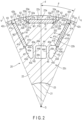
- FIG. 2 is a transverse cross-sectional view in which a magnetic pole in a rotor iron core is enlarged.
- a rotating electrical machine 1 is configured as, for example, an inner rotor type of rotating electrical machine, and includes an annular or cylindrical stator 10 supported in a fixing frame (not shown), and a columnar rotor 20 comprising a central axis (rotation center) G and supported inside the stator 10 rotatably and coaxially with the stator 10.
- the rotating electrical machine 1 is suitably applied to a drive motor or a power generator in a hybrid electric vehicle (HEV) or an electric vehicle (EV).
- HEV hybrid electric vehicle
- EV electric vehicle
- the stator 10 comprises a cylindrical stator iron core 11, and an armature winding (coil) 12 wound onto the stator iron core 11.
- the stator iron core 11 is structured by concentrically stacking a large number of annular electromagnetic steel plates (iron core pieces) formed of a magnetic material, for example, silicon steel.
- a plurality of slots 13 are formed in the inner circumferential portion of the stator iron core 11.
- the slots 13 are arranged at regular intervals in the circumferential direction of the stator iron core 11.
- the slots 13 are open on the inner circumferential surface of the stator iron core 11 and extend in a radiation direction from the inner circumferential surface.
- Each slot 13 extends over the entire length of the stator iron core 11 in the axial direction of the stator iron core 11.
- a plurality of (for example, 48) stator teeth 14 facing the rotor 20 are formed in the inner circumferential portion of the stator iron core 11.
- the armature windings 12 are inserted into the respective slots 13 and are wound onto the respective stator teeth 14. By supplying electricity to the armature windings 12, a predetermined flux linkage is formed in the stator 10 (stator teeth 14).
- the rotor 20 comprises a columnar rotation shaft 21 in which both ends are rotatably supported by a bearing (not shown), a cylindrical rotor iron core 22 fixed to substantially the middle portion in the axial direction of the rotation shaft 21, and a plurality of permanent magnets M1 and a plurality of permanent magnets M2 buried in the rotor iron core 22.
- the rotor 20 is coaxially provided inside the stator 10 such that a tiny gap (air gap) is interposed between the rotor 20 and the inner circumferential surface of the stator 10.
- the outer circumferential surface of the rotor 20 faces the inner circumferential surface of the stator 10 across an intervening tiny gap.
- the rotor iron core 22 comprises an inner hole 23 formed coaxially with the central axis G.
- the rotation shaft 21 is inserted and fitted into the inner hole 23 and extends coaxially with the rotor iron core 22.
- the rotor iron core 22 is structured as a stacked layer body prepared by concentrically stacking a large number of annular electromagnetic steel plates (iron core pieces) formed of a magnetic material, for example, silicon steel.
- the rotor iron core 22 comprises the above central axis G extending in the stacked direction of the iron core pieces, and an outer circumferential surface 22x facing the inner circumferential surface of the stator 10 across an intervening tiny gap (air gap).
- the rotor iron core 22 comprises a plurality of magnetic poles, for example, eight magnetic poles.
- a line which passes through the central axis G and the boundary between magnetic poles adjacent in the circumferential direction and extends in the radial direction of the rotor iron core 22 is referred to as a q-axis.
- an axis which is electrically spaced apart from each q-axis at 90° in the circumferential direction in other words, a line which extends from the central axis G in the radial direction and passes through the center in the circumferential direction of each magnetic pole, is referred to as a d-axis.
- a direction in which a flux linkage formed by the stator 10 easily flows is a q-axis.
- These d-axis and q-axis are alternately provided in the circumferential direction of the rotor iron core 22 with a predetermined phase.
- the portion of a magnetic pole of the rotor iron core 22 refers to the area between two q-axes adjacent in the circumferential direction (the circumferential angle area of 1/8 of the circumference).
- the center in the circumferential direction of a magnetic pole is a d-axis.
- the rotor iron core 22 comprises a plurality of rectangular first magnet accommodation areas 31 provided at regular intervals in the circumferential direction of the rotor iron core 22 in a state orthogonal to the respective d-axes (radial direction) of the rotor iron core 22.
- Permanent magnets M1 are accommodated in the respective first magnet accommodation areas 31 and are fixed to the rotor iron core 22 by, for example, an adhesive. Permanent magnets M1 are accommodated in these first magnet accommodation areas 31 one by one and form the eight magnetic poles described above. Each permanent magnet M1 is magnetized in a direction perpendicular to the long sides. For example, the transverse section of each permanent magnet M1 is formed into a rectangular shape like a long and thin plate. Each permanent magnet M1 has a length substantially equal to the axial length of the rotor iron core 22. Each permanent magnet M1 is buried over substantially the entire length of the rotor iron core 22. Each permanent magnet M1 may be configured by combining a plurality of axial (longitudinal) separate magnets. In this case, each permanent magnet M1 is formed such that the total length of the separate magnets is substantially equal to the axial length of the rotor iron core 22.
- Each first magnet accommodation area 31 is formed into a rectangular shape corresponding to the cross-sectional shape of each permanent magnet M1 so as to penetrate the rotor iron core 22 in the axial direction.
- Each first magnet accommodation area 31 comprises an end portion 31a and the other end portion 31b. These end portions 31a and 31b are open in the longitudinal direction.
- Each first magnet accommodation area 31 further comprises an outer edge (outer circumferential side long side) 31c on a side facing the outer circumferential surface 22x of the rotor iron core 22, and an inner edge (inner circumferential side long side) 31d on a side facing the central axis G.
- magnet retention protrusions 31e and 31f for restricting the motion of each permanent magnet M1 are formed in an area extending from the inner edge 31d to an end portion 31a of the first magnet accommodation area 31 and an area extending from the inner edge 31d to the other end portion 31b, respectively.
- first inner circumferential side magnetic voids 32 In each magnetic pole of the rotor iron core 22, a pair of first inner circumferential side magnetic voids 32 in contact with an end portion 31a and the other end portion 31b of the first magnet accommodation area 31 is provided.
- the first inner circumferential side magnetic voids 32 are formed so as to penetrate the rotor iron core 22 in the axial direction.
- Each of the first inner circumferential side magnetic voids 32 is a magnetic void containing a nonmagnetic material such as air, comprises edge 32a continuous with the outer edge 31c of the first magnet accommodation area 31, edge 32b extending at a slant from edge 32a along the first bridge portion 34 described later, and edge 32c extending from edge 32b and connected to the magnet retention protrusion 31e or 31f described above, functions as a flux barrier which prevents a short-circuit of a magnetic flux (magnet magnetic flux) in the end portion of permanent magnet M1 and also contributes to the reduction in the weight of the rotor iron core 22.
- a magnetic flux magnet magnetic flux
- first outer circumferential side magnetic voids 33 close to the first inner circumferential side magnetic voids 32 and open to the outside of the rotor iron core 22 through the outer circumferential surface 22x of the rotor iron core 22 is provided.
- the first outer circumferential side magnetic voids 33 are formed so as to penetrate the rotor iron core 22 in the axial direction.
- Each of the first outer circumferential side magnetic voids 33 is a magnetic void, includes edge 33a facing the first inner circumferential side magnetic void 32, edge 33b bending from edge 33a and partly open to the outer circumference of the rotor iron core 22 through the outer circumferential surface 22x while facing the outer circumferential surface 22x, and edge 33c extending from edge 33b and connected to edge 33a, prevents a short-circuit of a magnet magnetic flux in the rotor iron core 22 as edge 33b is open to the outside of the rotor iron core 22, and also contributes to the reduction in the weight of the rotor iron core 22.
- a pair of first bridge portions 34 in which the interval between them gradually expands from the outer circumferential side of the rotor iron core 22 to the inner circumferential side is provided between the respective first inner circumferential side magnetic voids 32 and the respective first outer circumferential side magnetic voids 33.
- the first magnet accommodation area 31, permanent magnet M1, the first inner circumferential side magnetic voids 32, the first outer circumferential side magnetic voids 33 and the first bridge portions 34 form a flux barrier of a first layer.
- the area on the outer circumferential side relative to this flux barrier of the first layer is a first iron core portion 22a.
- a pair of second magnet accommodation areas 41 in which an end portion 41a is located on the outer circumferential side of the rotor iron core 22 and the other end portion 41b is located on the inner circumferential side of the rotor iron core 22 is provided in a state interposing the first magnet accommodation area 21 between them.
- the second magnet accommodation areas 41 are arranged in, for example, substantially a V-shape so as to be line-symmetric with respect to the d-axis when they are viewed on a transverse section orthogonal to the central axis G of the rotor iron core 22.
- the second magnet accommodation areas 41 extend at a slant at angle ⁇ less than 90° with respect to the d-axis.
- the second magnet accommodation areas 41 are provided at a slant such that the distance from the d-axis gradually increases from the inner circumferential side of the rotor iron core 22 to the outer circumferential side.
- Angle ⁇ is not limited to the example shown in the figure and may be freely changed.
- Permanent magnets M2 are accommodated in the respective second magnet accommodation areas 41 and are fixed to the rotor iron core 22 by, for example, an adhesive. Permanent magnets M2 form each of the magnetic poles described above together with permanent magnet M1. Each permanent magnet M2 is magnetized in a direction perpendicular to the long sides. For example, the transverse section of each permanent magnet M2 is formed into a rectangular shape like a long and thin plate. Each permanent magnet M2 has a length substantially equal to the axial length of the rotor iron core 22. Each permanent magnet M2 is buried over substantially the entire length of the rotor iron core 22. Each permanent magnet M2 may be configured by combining a plurality of axial (longitudinal) separate magnets. In this case, each permanent magnet M2 is formed such that the total length of the separate magnets is substantially equal to the axial length of the rotor iron core 22.
- Each second magnet accommodation area 41 is formed into a rectangular shape corresponding to the cross-sectional shape of each permanent magnet M2 so as to penetrate the rotor iron core 22 in the axial direction.
- Each second magnet accommodation area 41 comprises an end portion 41a and the other end portion 41b in the longitudinal direction and comprises an edge 41c on a side facing the d-axis and the other edge 41d on a side facing the q-axis.
- magnet retention protrusions 41e and 41f for restricting the motion of each permanent magnet M2 are formed in an area extending from edge 41d to end portion 41a of the second magnet accommodation area 41 and an area extending from edge 41d to end portion 41b, respectively.
- each magnetic pole of the rotor iron core 22 a pair of second outer circumferential side magnetic voids 42 coming in contact with end portions 41a of the second magnet accommodation areas 41 and open to the outside of the rotor iron core 22 through the outer circumferential surface 22x of the rotor iron core 22 is provided.
- the second outer circumferential side magnetic voids 42 are formed so as to penetrate the rotor iron core 22 in the axial direction.
- Each of the second outer circumferential side magnetic voids 42 is a magnetic void, includes edge 42a extending from edge 41c of the second magnet accommodation area 41 so as to be flush with edge 41c, edge 42b bending from edge 42a and partly open to the outer circumference of the rotor iron core 22 through the outer circumferential surface 22x while facing the outer circumferential surface 22x, and edge 42c extending from edge 42b and connected to magnet retention protrusion 41e, functions as a flux barrier which prevents a short-circuit of a magnetic flux (magnet magnetic flux) in an end portion of permanent magnet M2, contributes to the reduction in the weight of the rotor iron core 22, and prevents a short-circuit of a magnet magnetic flux in the rotor iron core 22 especially as edge 42b is open to the outer circumference of the rotor iron core 22.
- edge 42a extending from edge 41c of the second magnet accommodation area 41 so as to be flush with edge 41c
- edge 42b bending from edge 42a and partly open to the outer circum
- each magnetic pole of the rotor iron core 22 a pair of second inner circumferential side magnetic voids 43 in contact with the other end portions 41b of the second magnet accommodation areas 41 is provided.
- the second inner circumferential side magnetic voids 43 are formed so as to penetrate the rotor iron core 22 in the axial direction.
- Each of the second inner circumferential side magnetic voids 43 is a magnetic void, includes edge 43a extending from a position which is in contact with edge 41c of the second magnet accommodation area 41 to the d-axis, edge 43b extending from edge 43a to the inner hole 23, edge 43c bending from edge 43b to the q-axis side, edge 43d rising from edge 43c toward edge 41d of the second magnet accommodation area 41, and edge 43e extending from edge 43d and connected to the magnet retention protrusion 41f described above, functions as a flux barrier which prevents a short-circuit of a magnetic flux (magnet magnetic flux) in the other end portion of permanent magnet M2, and also contributes to the reduction in the weight of the rotor iron core 22.
- a third magnetic void 44 is provided between the second inner circumferential side magnetic voids 43.
- the third magnetic void 44 is a magnetic void, has a rectangular cross-sectional shape consisting of four edges 44a to 44d, and is formed over the entire length of the rotor iron core 22 in the axial direction.
- edge 44a located on the outer circumferential side faces the first magnet accommodation area 31 in a state orthogonal to the d-axis
- edge 44c located on the inner circumferential side faces the inner hole 23 in a state parallel to edge 44a
- edges 44b and 44d located between these edges 44a and 44c are adjacent to the second bridge portions 45 described later in a state parallel to each other.
- Edge 44a on the outer circumferential side is located on the same line as a line connecting the outer circumferential side edges 43a of the second inner circumferential side magnetic voids 43 to each other.
- Edge 44a on the inner circumferential side is located on the same line as a line connecting the inner circumferential side edges 42c of the second inner circumferential side magnetic voids 43 to each other.
- the second inner circumferential side magnetic voids 43 are the passage of a refrigerant (cooling oil), and also contribute to the reduction in the weight of the rotor iron core 22.
- a pair of second bridge portions 45 is provided between the respective second inner circumferential side magnetic voids 43 and the third magnetic void 44.
- the second magnet accommodation areas 41, permanent magnets M2, the second outer circumferential side magnetic voids 42, the second inner circumferential side magnetic voids 43, the third magnetic void 44 and the second bridge portions 45 form a flux barrier of a second layer.
- the area surrounded by this flux barrier of the second layer and the flux barrier of the first layer described above is a second iron core portion 22b.
- the area on the inner circumferential side relative to the flux barrier of the second layer is a third iron core portion 22c.
- a pair of first bridge portions 34 in each magnetic pole of the rotor iron core 22 is connection elements which connect the first iron core portion 22a to the second iron core portion 22b, and is formed into a pillar shape extending at a slant such that the interval between them gradually expands from the inner circumferential side of the rotor iron core 22 to the outer circumferential side.
- the widths of the first bridge portions 34 are equal to each other, and are set in a required minimum state so as to be as less as possible to reduce the leak of a magnet magnetic flux but so as to sufficiently have strength for the great bending stress applied to the first bridge portions 34.
- the first iron core portion 22a of the rotor iron core 22 can be stably supported from the second iron core portion 22b side by the first bridge portions 34.
- a pair of second bridge portions 45 in each magnetic pole of the rotor iron core 22 is connection elements which connect the second iron core portion 22b to the third iron core portion 22c, and is formed into a pillar shape extending substantially parallel to the d-axis.
- the widths of the second bridge portions 45 are equal to each other, and are set in a required minimum state so as to be as less as possible to reduce the leak of a magnet magnetic flux but so as to be adapted to the centrifugal stress generated in the respective second bridge portions 45.
- the first bridge portions 34 incline such that the interval between them gradually expands from the inner circumferential side of the rotor iron core 22 to the outer circumferential side, the bending stress applied to the first bridge portions 34 can be reduced. In other words, as shown in FIG.
- the first bridge portions 34 are configured to extend parallel to each other, when force P similar to the above is applied to the outer circumferential surface 22x of the rotor torque 22, a great bending stress may be applied to the base portions of the first bridge portions 34, thereby deforming the first bridge portions 34 so as to collapse. This problem does not occur in the present embodiment.
- a pair of first cut holes 51 is provided such that the outer circumferential surface 22x communicates with the first outer circumferential side magnetic voids 33 and such that these first outer circumferential side magnetic voids 33 open into the outside of the outer circumferential surface 22x.
- a pair of second cut holes 52 is provided such that the outer circumferential surface 22x communicates with the second outer circumferential side magnetic voids 42 and such that these second outer circumferential side magnetic voids 42 open into the outside of the outer circumferential surface 22x.
- the first cut holes 51 and the second cut holes 52 extend over the rotor iron core 22 in the axial direction.
- first trench portions (recess portions or face cut portions) 61 are provided between the first outer circumferential side magnetic voids 33 for each magnetic pole.
- second trench portions (recess portions or face cut portions) 62 are provided between the first outer circumferential side magnetic voids 33 and the second outer circumferential side magnetic voids 42 for each magnetic pole.
- curved third trench portions (recess portions or face cut portions) 63 are provided between the second outer circumferential side magnetic voids 42 and the q-axes for each magnetic pole. These trench portions 61 to 63 extend over the rotor iron core 22 in the axial direction.
- the first trench portions 61 are provided between the first cut holes 51 in each magnetic pole, and the second trench portions 62 are provided between the first cut holes 51 and the second cut holes 52 in each magnetic pole, and the third trench portions 63 are provided between the second cut holes 52 and the q-axes in each magnetic pole. Since at least the first trench portions 61 and the second trench portions 62 are provided, the change of the magnetic resistance of the outer circumferential portion of the rotor iron core 22 can be suppressed to the extent of a practical level.
- width E1 of the first trench portions 61 in the circumferential direction and depth F1 of the first trench portions 61 in the radial direction are greater than width E2 of the second trench portions 62 and 63 in the circumferential direction and depth F2 of the second trench portions 62 and 63 in the radial direction.
- width A1 of each first cut hole 51 in the circumferential direction is less than width B1 of each first outer circumferential side magnetic void 33 in the circumferential direction.
- the portion in which each first cut hole 51 is narrower than each first outer circumferential side magnetic void 33 in the circumferential direction is chip portion 51a.
- Width A2 of each second cut hole 52 in the circumferential direction is less than width B2 of each second outer circumferential side magnetic void 42 in the circumferential direction.
- the portion in which each first cut hole 52 is narrower than each second outer circumferential side magnetic void 42 in the circumferential direction is chip portion 52a.
- the provision of chip portions 51a and 52a is important in addition to the provision of the first trench portions 61 and the second trench portions 62.
- the present invention is not limited to the embodiments described above, and may be implemented by modifying the constituent elements without departing from the spirit and scope of the invention.
- Various aspects of the invention can also be extracted from any appropriate combination of constituent elements disclosed in the embodiments. For example, some of the constituent elements disclosed in the embodiments may be deleted. Furthermore, the constituent elements described in different embodiments may be appropriately combined.
- the number of magnetic poles, dimension, shape or the like of the rotor is not limited to the embodiments described above, and may be changed in various ways depending on the design.
Landscapes
- Engineering & Computer Science (AREA)
- Power Engineering (AREA)
- Permanent Field Magnets Of Synchronous Machinery (AREA)
Abstract
Description
- Embodiments described herein relate generally to a rotor of a rotating electrical machine comprising a permanent magnet.
- In recent years, permanent magnets with a high magnetic energy product have been developed by the remarkable research and development of permanent magnets. A permanent magnet type of rotating electrical machine using these permanent magnets has been applied as an electric motor or power generator of a train or vehicle. This rotating electrical machine comprises a cylindrical stator, and a columnar rotor rotatably supported inside the stator. The rotor comprises a rotor iron core, and a plurality of permanent magnets buried in the rotor iron core. These permanent magnets form a plurality of magnetic poles in the circumferential direction of the rotor iron core.
-
- Patent Literature 1:
JP 2011-30427 A - Patent Literature 2:
JP 2011-147289 A - Patent Literature 3:
JP 2012-161243 A - Patent Literature 4:
JP 2013-176292 A - Patent Literature 5:
JP 2012-152082 A - Patent Literature 6:
JP 2013-21761 A - Patent Literature 7:
JP 2014-108025 A - In the above permanent magnet type of rotating electrical machine, it is important to sufficiently maintain the strength of the rotor iron core relative to a centrifugal force and electromagnetic attraction.
- According to an embodiment, a rotor comprises: a rotor iron core; a plurality of first magnet accommodation areas provided at regular intervals in a circumferential direction of the rotor iron core in a state orthogonal to a radial direction of the rotor iron core; a plurality of first permanent magnets accommodated in the respective first magnet accommodation areas and forming a plurality of magnetic poles in the circumferential direction of the rotor iron core; a pair of first inner circumferential side magnetic voids provided in each of the magnetic poles of the rotor iron core, and coming in contact with both end portions of the first magnet accommodation area; a pair of first outer circumferential side magnetic voids provided in each of the magnetic poles of the rotor iron core, close to the first inner circumferential side magnetic voids, and open to outside of the rotor iron core through an outer circumferential surface of the rotor iron core; a pair of first bridge portions provided between the respective first inner circumferential side magnetic voids and the respective first outer circumferential side magnetic voids in each of the magnetic poles of the rotor iron core such that a mutual interval expands from an outer circumferential side of the rotor iron core to an inner circumferential side; a pair of second magnet accommodation areas provided in a state interposing the first magnet accommodation area between them in each of the magnetic poles of the rotor iron core, and comprising an end portion located on the outer circumferential side of the rotor iron core and the other end portion located on the inner circumferential side of the rotor iron core; a plurality of second permanent magnets accommodated in the respective second magnet accommodation areas and forming the magnetic poles together with the first permanent magnets; a pair of second outer circumferential side magnetic voids coming in contact with the end portions of the second magnet accommodation areas, respectively, in each of the magnetic poles of the rotor iron core, and open to the outside of the rotor iron core through the outer circumferential surface of the rotor iron core; a pair of second inner circumferential side magnetic voids coming in contact with the other end portions of the second magnetic accommodation areas, respectively, in each of the magnetic poles of the rotor iron core; a third magnetic void provided between the second inner circumferential side magnetic voids in each of the magnetic poles of the rotor iron core; and a pair of second bridge portions provided between the respective second inner circumferential side magnetic voids and the third magnetic void in each of the magnetic poles of the rotor iron core.
-
-
FIG. 1 is a transverse cross-sectional view of a permanent magnet type of rotating electrical machine according to an embodiment. -
FIG. 2 is a transverse cross-sectional view showing the configuration of a magnetic pole according to the embodiment. -
FIG. 3 is a diagram showing an example of the force applied to a rotor iron core inFIG. 2 . -
FIG. 4 is a diagram showing an example in which bridge portions deform as a reference of the embodiment. -
FIG. 5 is a transverse cross-sectional view in which a relevant part ofFIG. 2 is enlarged. -
FIG. 6 is a transverse cross-sectional view in which another relevant part ofFIG. 2 is enlarged. - Embodiments of the present invention will be described hereinafter with reference to the accompanying drawings. Structures which are common to the embodiments are denoted by the same reference numbers, overlapping explanations being omitted. Each figure is an exemplary diagram of an embodiment to aid understanding of the embodiment. The shape, dimension, ratio or the like in the drawings may differ from those of the actual device, and may be appropriately changed in light of the following explanation and the known art.
-
FIG. 1 is a transverse cross-sectional view of a permanent magnet type of rotating electrical machine according to an embodiment.FIG. 2 is a transverse cross-sectional view in which a magnetic pole in a rotor iron core is enlarged. - As shown in
FIG. 1 , a rotating electrical machine 1 is configured as, for example, an inner rotor type of rotating electrical machine, and includes an annular orcylindrical stator 10 supported in a fixing frame (not shown), and acolumnar rotor 20 comprising a central axis (rotation center) G and supported inside thestator 10 rotatably and coaxially with thestator 10. For example, the rotating electrical machine 1 is suitably applied to a drive motor or a power generator in a hybrid electric vehicle (HEV) or an electric vehicle (EV). - The
stator 10 comprises a cylindricalstator iron core 11, and an armature winding (coil) 12 wound onto thestator iron core 11. Thestator iron core 11 is structured by concentrically stacking a large number of annular electromagnetic steel plates (iron core pieces) formed of a magnetic material, for example, silicon steel. A plurality ofslots 13 are formed in the inner circumferential portion of thestator iron core 11. - The
slots 13 are arranged at regular intervals in the circumferential direction of thestator iron core 11. Theslots 13 are open on the inner circumferential surface of thestator iron core 11 and extend in a radiation direction from the inner circumferential surface. Eachslot 13 extends over the entire length of thestator iron core 11 in the axial direction of thestator iron core 11. As theseslots 13 are formed, a plurality of (for example, 48)stator teeth 14 facing therotor 20 are formed in the inner circumferential portion of thestator iron core 11. Thearmature windings 12 are inserted into therespective slots 13 and are wound onto therespective stator teeth 14. By supplying electricity to thearmature windings 12, a predetermined flux linkage is formed in the stator 10 (stator teeth 14). - The
rotor 20 comprises acolumnar rotation shaft 21 in which both ends are rotatably supported by a bearing (not shown), a cylindricalrotor iron core 22 fixed to substantially the middle portion in the axial direction of therotation shaft 21, and a plurality of permanent magnets M1 and a plurality of permanent magnets M2 buried in therotor iron core 22. Therotor 20 is coaxially provided inside thestator 10 such that a tiny gap (air gap) is interposed between therotor 20 and the inner circumferential surface of thestator 10. The outer circumferential surface of therotor 20 faces the inner circumferential surface of thestator 10 across an intervening tiny gap. Therotor iron core 22 comprises aninner hole 23 formed coaxially with the central axis G. Therotation shaft 21 is inserted and fitted into theinner hole 23 and extends coaxially with therotor iron core 22. - The
rotor iron core 22 is structured as a stacked layer body prepared by concentrically stacking a large number of annular electromagnetic steel plates (iron core pieces) formed of a magnetic material, for example, silicon steel. Therotor iron core 22 comprises the above central axis G extending in the stacked direction of the iron core pieces, and an outercircumferential surface 22x facing the inner circumferential surface of thestator 10 across an intervening tiny gap (air gap). - The
rotor iron core 22 comprises a plurality of magnetic poles, for example, eight magnetic poles. In therotor iron core 22, a line which passes through the central axis G and the boundary between magnetic poles adjacent in the circumferential direction and extends in the radial direction of therotor iron core 22 is referred to as a q-axis. Further, an axis which is electrically spaced apart from each q-axis at 90° in the circumferential direction, in other words, a line which extends from the central axis G in the radial direction and passes through the center in the circumferential direction of each magnetic pole, is referred to as a d-axis. A direction in which a flux linkage formed by thestator 10 easily flows is a q-axis. These d-axis and q-axis are alternately provided in the circumferential direction of therotor iron core 22 with a predetermined phase. The portion of a magnetic pole of therotor iron core 22 refers to the area between two q-axes adjacent in the circumferential direction (the circumferential angle area of 1/8 of the circumference). The center in the circumferential direction of a magnetic pole is a d-axis. - As shown in
FIG. 2 , therotor iron core 22 comprises a plurality of rectangular firstmagnet accommodation areas 31 provided at regular intervals in the circumferential direction of therotor iron core 22 in a state orthogonal to the respective d-axes (radial direction) of therotor iron core 22. - Permanent magnets M1 are accommodated in the respective first
magnet accommodation areas 31 and are fixed to therotor iron core 22 by, for example, an adhesive. Permanent magnets M1 are accommodated in these firstmagnet accommodation areas 31 one by one and form the eight magnetic poles described above. Each permanent magnet M1 is magnetized in a direction perpendicular to the long sides. For example, the transverse section of each permanent magnet M1 is formed into a rectangular shape like a long and thin plate. Each permanent magnet M1 has a length substantially equal to the axial length of therotor iron core 22. Each permanent magnet M1 is buried over substantially the entire length of therotor iron core 22. Each permanent magnet M1 may be configured by combining a plurality of axial (longitudinal) separate magnets. In this case, each permanent magnet M1 is formed such that the total length of the separate magnets is substantially equal to the axial length of therotor iron core 22. - Each first
magnet accommodation area 31 is formed into a rectangular shape corresponding to the cross-sectional shape of each permanent magnet M1 so as to penetrate therotor iron core 22 in the axial direction. Each firstmagnet accommodation area 31 comprises an end portion 31a and theother end portion 31b. Theseend portions 31a and 31b are open in the longitudinal direction. Each firstmagnet accommodation area 31 further comprises an outer edge (outer circumferential side long side) 31c on a side facing the outercircumferential surface 22x of therotor iron core 22, and an inner edge (inner circumferential side long side) 31d on a side facing the central axis G. In therotor iron core 22,magnet retention protrusions inner edge 31d to an end portion 31a of the firstmagnet accommodation area 31 and an area extending from theinner edge 31d to theother end portion 31b, respectively. - In each magnetic pole of the
rotor iron core 22, a pair of first inner circumferential sidemagnetic voids 32 in contact with an end portion 31a and theother end portion 31b of the firstmagnet accommodation area 31 is provided. The first inner circumferential sidemagnetic voids 32 are formed so as to penetrate therotor iron core 22 in the axial direction. Each of the first inner circumferential sidemagnetic voids 32 is a magnetic void containing a nonmagnetic material such as air, comprisesedge 32a continuous with the outer edge 31c of the firstmagnet accommodation area 31,edge 32b extending at a slant fromedge 32a along thefirst bridge portion 34 described later, andedge 32c extending fromedge 32b and connected to themagnet retention protrusion rotor iron core 22. - In each magnetic pole of the
rotor iron core 22, a pair of first outer circumferential sidemagnetic voids 33 close to the first inner circumferential sidemagnetic voids 32 and open to the outside of therotor iron core 22 through the outercircumferential surface 22x of therotor iron core 22 is provided. The first outer circumferential sidemagnetic voids 33 are formed so as to penetrate therotor iron core 22 in the axial direction. Each of the first outer circumferential sidemagnetic voids 33 is a magnetic void, includesedge 33a facing the first inner circumferential sidemagnetic void 32,edge 33b bending fromedge 33a and partly open to the outer circumference of therotor iron core 22 through the outercircumferential surface 22x while facing the outercircumferential surface 22x, andedge 33c extending fromedge 33b and connected to edge 33a, prevents a short-circuit of a magnet magnetic flux in therotor iron core 22 asedge 33b is open to the outside of therotor iron core 22, and also contributes to the reduction in the weight of therotor iron core 22. - In each magnetic pole of the
rotor iron core 22, a pair offirst bridge portions 34 in which the interval between them gradually expands from the outer circumferential side of therotor iron core 22 to the inner circumferential side is provided between the respective first inner circumferential sidemagnetic voids 32 and the respective first outer circumferential sidemagnetic voids 33. - The first
magnet accommodation area 31, permanent magnet M1, the first inner circumferential sidemagnetic voids 32, the first outer circumferential sidemagnetic voids 33 and thefirst bridge portions 34 form a flux barrier of a first layer. The area on the outer circumferential side relative to this flux barrier of the first layer is a firstiron core portion 22a. - In each magnetic pole of the
rotor iron core 22, a pair of secondmagnet accommodation areas 41 in which anend portion 41a is located on the outer circumferential side of therotor iron core 22 and theother end portion 41b is located on the inner circumferential side of therotor iron core 22 is provided in a state interposing the firstmagnet accommodation area 21 between them. The secondmagnet accommodation areas 41 are arranged in, for example, substantially a V-shape so as to be line-symmetric with respect to the d-axis when they are viewed on a transverse section orthogonal to the central axis G of therotor iron core 22. The secondmagnet accommodation areas 41 extend at a slant at angle θ less than 90° with respect to the d-axis. In other words, the secondmagnet accommodation areas 41 are provided at a slant such that the distance from the d-axis gradually increases from the inner circumferential side of therotor iron core 22 to the outer circumferential side. Angle θ is not limited to the example shown in the figure and may be freely changed. - Permanent magnets M2 are accommodated in the respective second
magnet accommodation areas 41 and are fixed to therotor iron core 22 by, for example, an adhesive. Permanent magnets M2 form each of the magnetic poles described above together with permanent magnet M1. Each permanent magnet M2 is magnetized in a direction perpendicular to the long sides. For example, the transverse section of each permanent magnet M2 is formed into a rectangular shape like a long and thin plate. Each permanent magnet M2 has a length substantially equal to the axial length of therotor iron core 22. Each permanent magnet M2 is buried over substantially the entire length of therotor iron core 22. Each permanent magnet M2 may be configured by combining a plurality of axial (longitudinal) separate magnets. In this case, each permanent magnet M2 is formed such that the total length of the separate magnets is substantially equal to the axial length of therotor iron core 22. - Each second
magnet accommodation area 41 is formed into a rectangular shape corresponding to the cross-sectional shape of each permanent magnet M2 so as to penetrate therotor iron core 22 in the axial direction. Each secondmagnet accommodation area 41 comprises anend portion 41a and theother end portion 41b in the longitudinal direction and comprises anedge 41c on a side facing the d-axis and theother edge 41d on a side facing the q-axis. In therotor iron core 22,magnet retention protrusions edge 41d to endportion 41a of the secondmagnet accommodation area 41 and an area extending fromedge 41d to endportion 41b, respectively. - In each magnetic pole of the
rotor iron core 22, a pair of second outer circumferential sidemagnetic voids 42 coming in contact withend portions 41a of the secondmagnet accommodation areas 41 and open to the outside of therotor iron core 22 through the outercircumferential surface 22x of therotor iron core 22 is provided. The second outer circumferential sidemagnetic voids 42 are formed so as to penetrate therotor iron core 22 in the axial direction. Each of the second outer circumferential sidemagnetic voids 42 is a magnetic void, includesedge 42a extending fromedge 41c of the secondmagnet accommodation area 41 so as to be flush withedge 41c,edge 42b bending fromedge 42a and partly open to the outer circumference of therotor iron core 22 through the outercircumferential surface 22x while facing the outercircumferential surface 22x, andedge 42c extending fromedge 42b and connected tomagnet retention protrusion 41e, functions as a flux barrier which prevents a short-circuit of a magnetic flux (magnet magnetic flux) in an end portion of permanent magnet M2, contributes to the reduction in the weight of therotor iron core 22, and prevents a short-circuit of a magnet magnetic flux in therotor iron core 22 especially asedge 42b is open to the outer circumference of therotor iron core 22. - In each magnetic pole of the
rotor iron core 22, a pair of second inner circumferential sidemagnetic voids 43 in contact with theother end portions 41b of the secondmagnet accommodation areas 41 is provided. The second inner circumferential sidemagnetic voids 43 are formed so as to penetrate therotor iron core 22 in the axial direction. Each of the second inner circumferential sidemagnetic voids 43 is a magnetic void, includesedge 43a extending from a position which is in contact withedge 41c of the secondmagnet accommodation area 41 to the d-axis,edge 43b extending fromedge 43a to theinner hole 23,edge 43c bending fromedge 43b to the q-axis side,edge 43d rising fromedge 43c towardedge 41d of the secondmagnet accommodation area 41, andedge 43e extending fromedge 43d and connected to themagnet retention protrusion 41f described above, functions as a flux barrier which prevents a short-circuit of a magnetic flux (magnet magnetic flux) in the other end portion of permanent magnet M2, and also contributes to the reduction in the weight of therotor iron core 22. - In each magnetic pole of the
rotor iron core 22, a thirdmagnetic void 44 is provided between the second inner circumferential sidemagnetic voids 43. The thirdmagnetic void 44 is a magnetic void, has a rectangular cross-sectional shape consisting of fouredges 44a to 44d, and is formed over the entire length of therotor iron core 22 in the axial direction. Of the fouredges 44a to 44d forming the thirdmagnetic void 44,edge 44a located on the outer circumferential side faces the firstmagnet accommodation area 31 in a state orthogonal to the d-axis, andedge 44c located on the inner circumferential side faces theinner hole 23 in a state parallel toedge 44a, and edges 44b and 44d located between theseedges second bridge portions 45 described later in a state parallel to each other.Edge 44a on the outer circumferential side is located on the same line as a line connecting the outer circumferential side edges 43a of the second inner circumferential sidemagnetic voids 43 to each other.Edge 44a on the inner circumferential side is located on the same line as a line connecting the inner circumferential side edges 42c of the second inner circumferential sidemagnetic voids 43 to each other. The second inner circumferential sidemagnetic voids 43 are the passage of a refrigerant (cooling oil), and also contribute to the reduction in the weight of therotor iron core 22. - In each magnetic pole of the
rotor iron core 22, a pair ofsecond bridge portions 45 is provided between the respective second inner circumferential sidemagnetic voids 43 and the thirdmagnetic void 44. - The second
magnet accommodation areas 41, permanent magnets M2, the second outer circumferential sidemagnetic voids 42, the second inner circumferential sidemagnetic voids 43, the thirdmagnetic void 44 and thesecond bridge portions 45 form a flux barrier of a second layer. The area surrounded by this flux barrier of the second layer and the flux barrier of the first layer described above is a secondiron core portion 22b. The area on the inner circumferential side relative to the flux barrier of the second layer is a thirdiron core portion 22c. - A pair of
first bridge portions 34 in each magnetic pole of therotor iron core 22 is connection elements which connect the firstiron core portion 22a to the secondiron core portion 22b, and is formed into a pillar shape extending at a slant such that the interval between them gradually expands from the inner circumferential side of therotor iron core 22 to the outer circumferential side. The widths of thefirst bridge portions 34 are equal to each other, and are set in a required minimum state so as to be as less as possible to reduce the leak of a magnet magnetic flux but so as to sufficiently have strength for the great bending stress applied to thefirst bridge portions 34. Even if an electromagnetic force in the circumferential direction is applied to the firstiron core portion 22a of therotor iron core 22 under a situation where a large torque is generated, the firstiron core portion 22a can be stably supported from the secondiron core portion 22b side by thefirst bridge portions 34. - A pair of
second bridge portions 45 in each magnetic pole of therotor iron core 22 is connection elements which connect the secondiron core portion 22b to the thirdiron core portion 22c, and is formed into a pillar shape extending substantially parallel to the d-axis. The widths of thesecond bridge portions 45 are equal to each other, and are set in a required minimum state so as to be as less as possible to reduce the leak of a magnet magnetic flux but so as to be adapted to the centrifugal stress generated in the respectivesecond bridge portions 45. Even if an electromagnetic force in the circumferential direction is applied to the firstiron core portion 22a and the secondiron core portion 22b of therotor iron core 22 under a situation where a large torque is generated, the firstiron core portion 22a and the secondiron core portion 22b can be stably supported from the thirdiron core portion 22c side by the second bridges 45. - In particular, as the
first bridge portions 34 incline such that the interval between them gradually expands from the inner circumferential side of therotor iron core 22 to the outer circumferential side, the bending stress applied to thefirst bridge portions 34 can be reduced. In other words, as shown inFIG. 3 , even if force P in the arrow direction such as a centrifugal force or electromagnetic attraction is applied to the outercircumferential surface 22x of therotor torque 22 in a state where therotor iron core 22 generates toque clockwise in the figure, the bending stress applied to the base portions of thefirst bridge portions 34 can be reduced, thereby minimizing the deformation of thefirst bridge portions 34 and the deformation of the outer circumferential part of therotor iron core 22 in connection with the deformation of thefirst bridge portions 34. - If, as shown in
FIG. 4 , thefirst bridge portions 34 are configured to extend parallel to each other, when force P similar to the above is applied to the outercircumferential surface 22x of therotor torque 22, a great bending stress may be applied to the base portions of thefirst bridge portions 34, thereby deforming thefirst bridge portions 34 so as to collapse. This problem does not occur in the present embodiment. - In each magnetic pole of the
rotor iron core 22, as shown in closeup inFIG. 5 , a pair of first cut holes 51 is provided such that the outercircumferential surface 22x communicates with the first outer circumferential sidemagnetic voids 33 and such that these first outer circumferential sidemagnetic voids 33 open into the outside of the outercircumferential surface 22x. In each magnetic pole of therotor iron core 22, as shown in closeup inFIG. 6 , a pair of second cut holes 52 is provided such that the outercircumferential surface 22x communicates with the second outer circumferential sidemagnetic voids 42 and such that these second outer circumferential sidemagnetic voids 42 open into the outside of the outercircumferential surface 22x. The first cut holes 51 and the second cut holes 52 extend over therotor iron core 22 in the axial direction. - On the outer
circumferential surface 22x of therotor iron core 22, at least two curved first trench portions (recess portions or face cut portions) 61 are provided between the first outer circumferential sidemagnetic voids 33 for each magnetic pole. On the outercircumferential surface 22x of therotor iron core 22, at least two curved second trench portions (recess portions or face cut portions) 62 are provided between the first outer circumferential sidemagnetic voids 33 and the second outer circumferential sidemagnetic voids 42 for each magnetic pole. - On the outer
circumferential surface 22x of therotor iron core 22, curved third trench portions (recess portions or face cut portions) 63 are provided between the second outer circumferential sidemagnetic voids 42 and the q-axes for each magnetic pole. Thesetrench portions 61 to 63 extend over therotor iron core 22 in the axial direction. - In a manner similar to that of the present embodiment, in a structure in which the flux barrier of the first layer is open to the outside of the
rotor iron core 22 through the first cut holes 51, and further, the flux barrier of the second layer is open to the outside of therotor iron core 22 through the second cut holes 52, as the magnetic resistance of the outer circumferential portion of therotor iron core 22 is steeply changed, noise, oscillation, torque pulsation and the like easily occur. - In consideration of this matter, in the present embodiment, on the outer
circumferential surface 22x of therotor iron core 22, thefirst trench portions 61 are provided between the first cut holes 51 in each magnetic pole, and thesecond trench portions 62 are provided between the first cut holes 51 and the second cut holes 52 in each magnetic pole, and thethird trench portions 63 are provided between the second cut holes 52 and the q-axes in each magnetic pole. Since at least thefirst trench portions 61 and thesecond trench portions 62 are provided, the change of the magnetic resistance of the outer circumferential portion of therotor iron core 22 can be suppressed to the extent of a practical level. - Further, width E1 of the
first trench portions 61 in the circumferential direction and depth F1 of thefirst trench portions 61 in the radial direction are greater than width E2 of thesecond trench portions second trench portions rotor iron core 22 and thestator 10 is made more appropriate. In this way, noise, oscillation and torque pulsation can be more effectively reduced. - In addition, width A1 of each
first cut hole 51 in the circumferential direction is less than width B1 of each first outer circumferential sidemagnetic void 33 in the circumferential direction. The portion in which eachfirst cut hole 51 is narrower than each first outer circumferential sidemagnetic void 33 in the circumferential direction ischip portion 51a. Width A2 of eachsecond cut hole 52 in the circumferential direction is less than width B2 of each second outer circumferential sidemagnetic void 42 in the circumferential direction. The portion in which eachfirst cut hole 52 is narrower than each second outer circumferential sidemagnetic void 42 in the circumferential direction ischip portion 52a. - To more smoothly change the magnetic resistance of the outer circumferential portion of the
rotor iron core 22, the provision ofchip portions first trench portions 61 and thesecond trench portions 62. - In particular, the ratio (= D1/C1) between depth D1 of each
first cut hole 51 in the radial direction and width C1 [= (B1 - A1)/2] ofchip portion 51a in the circumferential direction is set in the range of 0.7 to 1.1. The ratio (= D2/C2) between depth D2 of eachsecond cut hole 52 in the radial direction and width C2 [= (B2 - A2)/2] ofchip portion 52a in the circumferential direction is set in the range of 0.7 to 1.1. These ranges are desirable to more smoothly change the magnetic resistance of the outer circumferential portion of therotor iron core 22. - The present invention is not limited to the embodiments described above, and may be implemented by modifying the constituent elements without departing from the spirit and scope of the invention. Various aspects of the invention can also be extracted from any appropriate combination of constituent elements disclosed in the embodiments. For example, some of the constituent elements disclosed in the embodiments may be deleted. Furthermore, the constituent elements described in different embodiments may be appropriately combined.
- For example, the number of magnetic poles, dimension, shape or the like of the rotor is not limited to the embodiments described above, and may be changed in various ways depending on the design.
Claims (5)
- A rotor comprising:a rotor iron core;a plurality of first magnet accommodation areas provided at regular intervals in a circumferential direction of the rotor iron core in a state orthogonal to a radial direction of the rotor iron core;a plurality of first permanent magnets accommodated in the respective first magnet accommodation areas and forming a plurality of magnetic poles in the circumferential direction of the rotor iron core;a pair of first inner circumferential side magnetic voids provided in each of the magnetic poles of the rotor iron core, and coming in contact with both end portions of the first magnet accommodation area;a pair of first outer circumferential side magnetic voids provided in each of the magnetic poles of the rotor iron core, close to the first inner circumferential side magnetic voids, and open to outside of the rotor iron core through an outer circumferential surface of the rotor iron core;a pair of first bridge portions provided between the respective first inner circumferential side magnetic voids and the respective first outer circumferential side magnetic voids in each of the magnetic poles of the rotor iron core such that a mutual interval expands from an outer circumferential side of the rotor iron core to an inner circumferential side;a pair of second magnet accommodation areas provided in a state interposing the first magnet accommodation area between them in each of the magnetic poles of the rotor iron core, and comprising an end portion located on the outer circumferential side of the rotor iron core and the other end portion located on the inner circumferential side of the rotor iron core;a plurality of second permanent magnets accommodated in the respective second magnet accommodation areas and forming the magnetic poles together with the first permanent magnets;a pair of second outer circumferential side magnetic voids coming in contact with the end portions of the second magnet accommodation areas, respectively, in each of the magnetic poles of the rotor iron core, and open to the outside of the rotor iron core through the outer circumferential surface of the rotor iron core;a pair of second inner circumferential side magnetic voids coming in contact with the other end portions of the second magnetic accommodation areas, respectively, in each of the magnetic poles of the rotor iron core;a third magnetic void provided between the second inner circumferential side magnetic voids in each of the magnetic poles of the rotor iron core; anda pair of second bridge portions provided between the respective second inner circumferential side magnetic voids and the third magnetic void in each of the magnetic poles of the rotor iron core.
- The rotor of claim 1, further comprising:at least two first trench portions provided between the first outer circumferential side magnetic voids for each of the magnetic poles on the outer circumferential surface of the rotor iron core; andat least two second trench portions provided between the respective first outer circumferential side magnetic voids and the respective second outer circumferential side magnetic voids for each of the magnetic poles on the outer circumferential surface of the rotor iron core.
- The rotor of claim 2, wherein
width E1 of each of the first trench portions in the circumferential direction and depth F1 of each of the first trench portions in the radial direction are greater than width E2 of each of the second trench portions in the circumferential direction and depth F2 of each of the second trench portions in the radial direction. - The rotor of claim 1, further comprising:a plurality of first cut holes communicating with the respective first outer circumferential side magnetic voids, open on the outer circumferential surface of the rotor iron core, and causing the respective first outer circumferential side magnetic voids to be open to the outside of the rotor iron core; anda plurality of second cut holes communicating with the respective second outer circumferential side magnetic voids, open on the outer circumferential surface of the rotor iron core, and causing the respective second outer circumferential side magnetic voids to be open to the outside of the rotor iron core,whereinwidth A1 of each of the first cut holes in the circumferential direction is less than width B1 of each of the first outer circumferential side magnetic voids in the circumferential direction, andwidth A2 of each of the second cut holes in the circumferential direction is less than width B2 of each of the second outer circumferential side magnetic voids in the circumferential direction.
- The rotor of claim 4, whereina ratio (= D1/C1) between depth D1 of each of the first cut holes in the radial direction and width C1 [= (B1 - A1)/2] of a portion (chip portion) in which each of the first cut holes is narrower than the first outer circumferential side magnetic void in the circumferential direction in the circumferential direction is 0.7 to 1.1, anda ratio (= D2/C2) between depth D2 of each of the second cut holes in the radial direction and width C2 [= (B2 - A2)/2] of a portion (chip portion) in which each of the second cut holes is narrower than the second outer circumferential side magnetic void in the circumferential direction in the circumferential direction is 0.7 to 1.1.
Applications Claiming Priority (1)
| Application Number | Priority Date | Filing Date | Title |
|---|---|---|---|
| PCT/JP2022/000102 WO2023132011A1 (en) | 2022-01-05 | 2022-01-05 | Rotor |
Publications (2)
| Publication Number | Publication Date |
|---|---|
| EP4462650A1 true EP4462650A1 (en) | 2024-11-13 |
| EP4462650A4 EP4462650A4 (en) | 2025-08-27 |
Family
ID=87073461
Family Applications (1)
| Application Number | Title | Priority Date | Filing Date |
|---|---|---|---|
| EP22902478.1A Pending EP4462650A4 (en) | 2022-01-05 | 2022-01-05 | Rotor |
Country Status (5)
| Country | Link |
|---|---|
| US (1) | US12537404B2 (en) |
| EP (1) | EP4462650A4 (en) |
| JP (1) | JP7520998B2 (en) |
| CN (1) | CN116830425A (en) |
| WO (1) | WO2023132011A1 (en) |
Family Cites Families (26)
| Publication number | Priority date | Publication date | Assignee | Title |
|---|---|---|---|---|
| JP4120208B2 (en) | 2001-11-20 | 2008-07-16 | アイシン精機株式会社 | Permanent magnet type synchronous machine |
| JP2004104962A (en) | 2002-09-12 | 2004-04-02 | Toshiba Industrial Products Manufacturing Corp | Permanent magnet type reluctance type rotating electric machine |
| JP4449035B2 (en) * | 2004-03-10 | 2010-04-14 | 日立オートモティブシステムズ株式会社 | Permanent magnet rotating electric machine for electric vehicles |
| JP5433198B2 (en) | 2008-10-16 | 2014-03-05 | 日立オートモティブシステムズ株式会社 | Rotating electric machines and electric vehicles |
| JP5608377B2 (en) | 2010-01-15 | 2014-10-15 | 本田技研工業株式会社 | Rotating electric machine |
| CN102263445B (en) * | 2010-05-31 | 2016-07-06 | 德昌电机(深圳)有限公司 | Brushless electric machine |
| WO2012014836A1 (en) * | 2010-07-30 | 2012-02-02 | 本田技研工業株式会社 | Rotor and motor |
| JP5120440B2 (en) | 2010-11-12 | 2013-01-16 | ダイキン工業株式会社 | Rotor |
| JP5652221B2 (en) | 2011-01-21 | 2015-01-14 | ダイキン工業株式会社 | Rotor |
| JP2012161226A (en) * | 2011-02-03 | 2012-08-23 | Toyota Motor Corp | Rotor for rotary electric machine |
| JP5447418B2 (en) * | 2011-03-28 | 2014-03-19 | 株式会社豊田自動織機 | Rotating electric machine permanent magnet embedded rotor and rotating electric machine |
| JP5720445B2 (en) | 2011-07-07 | 2015-05-20 | ダイキン工業株式会社 | Rotating electric machine |
| JP5612632B2 (en) | 2012-06-01 | 2014-10-22 | 日立オートモティブシステムズ株式会社 | Permanent magnet rotating electric machine |
| JP5851365B2 (en) | 2012-08-31 | 2016-02-03 | 日立オートモティブシステムズ株式会社 | Rotating electric machine |
| JP5958305B2 (en) | 2012-11-29 | 2016-07-27 | スズキ株式会社 | IPM type electric rotating machine |
| JP6110151B2 (en) * | 2013-02-07 | 2017-04-05 | 本田技研工業株式会社 | Rotating electrical machine rotor |
| JP5650276B2 (en) | 2013-05-07 | 2015-01-07 | 日立オートモティブシステムズ株式会社 | Rotor and rotating electric machine equipped with the same |
| JP2016032424A (en) * | 2014-07-30 | 2016-03-07 | トヨタ自動車株式会社 | Manufacturing method of rotor core |
| WO2016104418A1 (en) * | 2014-12-22 | 2016-06-30 | 三菱電機株式会社 | Rotor for rotary electrical machine |
| JP2018085819A (en) | 2016-11-22 | 2018-05-31 | アイシン・エィ・ダブリュ株式会社 | Rotor |
| GB201619856D0 (en) * | 2016-11-24 | 2017-01-11 | Jaguar Land Rover Ltd | Electric machine apparatus |
| JP2018110502A (en) * | 2017-01-06 | 2018-07-12 | 日立オートモティブシステムズ株式会社 | Rotary electric machine, and vehicle electric accessory system using the same |
| JP2019140843A (en) * | 2018-02-14 | 2019-08-22 | アイシン・エィ・ダブリュ株式会社 | Rotor for rotary electric machine |
| US11594921B2 (en) * | 2019-12-11 | 2023-02-28 | GM Global Technology Operations LLC | Electric machine with noise-reducing rotor notches |
| JP7468640B2 (en) * | 2020-06-08 | 2024-04-16 | 株式会社アイシン | Rotor for rotating electrical machine |
| WO2022059199A1 (en) * | 2020-09-18 | 2022-03-24 | 株式会社 東芝 | Rotor |
-
2022
- 2022-01-05 JP JP2022559305A patent/JP7520998B2/en active Active
- 2022-01-05 CN CN202280005028.7A patent/CN116830425A/en active Pending
- 2022-01-05 EP EP22902478.1A patent/EP4462650A4/en active Pending
- 2022-01-05 WO PCT/JP2022/000102 patent/WO2023132011A1/en not_active Ceased
-
2023
- 2023-05-15 US US18/317,842 patent/US12537404B2/en active Active
Also Published As
| Publication number | Publication date |
|---|---|
| US20230283127A1 (en) | 2023-09-07 |
| US12537404B2 (en) | 2026-01-27 |
| JP7520998B2 (en) | 2024-07-23 |
| CN116830425A (en) | 2023-09-29 |
| EP4462650A4 (en) | 2025-08-27 |
| WO2023132011A1 (en) | 2023-07-13 |
| JPWO2023132011A1 (en) | 2023-07-13 |
Similar Documents
| Publication | Publication Date | Title |
|---|---|---|
| US12119712B2 (en) | Rotor of rotary electric machine | |
| EP2216883B1 (en) | Rotor for a rotating electrical machine | |
| EP0909003B1 (en) | A motor using a rotor including interior permanent magnets | |
| KR100615878B1 (en) | IPM motors, motor vehicles, electric cars and trams | |
| US12191713B2 (en) | Rotor of rotary electric machine | |
| EP3675328A1 (en) | Rotary electric device | |
| US11837919B2 (en) | Rotary electric machine | |
| CN117280568A (en) | rotor of rotating electrical machine | |
| US12456889B2 (en) | Rotor and rotating electrical machine | |
| EP3926798A1 (en) | Direct-start synchronous reluctance electric motor rotor structure, electric motor and compressor | |
| EP4047788B1 (en) | Rotary electric machine | |
| CN113273057A (en) | Interior permanent magnet machine with flux distribution gap | |
| CN109997290B (en) | Synchronous reluctance type rotating electrical machine | |
| JP2019165592A (en) | Rotary electric machine | |
| CN106063085B (en) | Rotor | |
| US12537404B2 (en) | Rotor | |
| JP2020182358A (en) | Rotor of rotating electric machine | |
| KR20200085125A (en) | Rotor for motor | |
| US12136854B2 (en) | Rotating electrical machine | |
| JP2020156199A (en) | Rotary electric machine | |
| JP7224986B2 (en) | Rotating electric machine | |
| JP2008206351A (en) | PM synchronous motor | |
| EP4447272A1 (en) | Rotor of rotary electric machine | |
| JP2021048682A (en) | Rotor |
Legal Events
| Date | Code | Title | Description |
|---|---|---|---|
| STAA | Information on the status of an ep patent application or granted ep patent |
Free format text: STATUS: UNKNOWN |
|
| STAA | Information on the status of an ep patent application or granted ep patent |
Free format text: STATUS: THE INTERNATIONAL PUBLICATION HAS BEEN MADE |
|
| PUAI | Public reference made under article 153(3) epc to a published international application that has entered the european phase |
Free format text: ORIGINAL CODE: 0009012 |
|
| STAA | Information on the status of an ep patent application or granted ep patent |
Free format text: STATUS: REQUEST FOR EXAMINATION WAS MADE |
|
| 17P | Request for examination filed |
Effective date: 20230615 |
|
| AK | Designated contracting states |
Kind code of ref document: A1 Designated state(s): AL AT BE BG CH CY CZ DE DK EE ES FI FR GB GR HR HU IE IS IT LI LT LU LV MC MK MT NL NO PL PT RO RS SE SI SK SM TR |
|
| DAV | Request for validation of the european patent (deleted) | ||
| DAX | Request for extension of the european patent (deleted) | ||
| A4 | Supplementary search report drawn up and despatched |
Effective date: 20250728 |
|
| RIC1 | Information provided on ipc code assigned before grant |
Ipc: H02K 1/276 20220101AFI20250722BHEP Ipc: H02K 29/03 20060101ALN20250722BHEP |
|
| RAP1 | Party data changed (applicant data changed or rights of an application transferred) |
Owner name: KABUSHIKI KAISHA TOSHIBA |