EP4462405A1 - Vehicle driving assistance control method and apparatus, and vehicle and storage medium - Google Patents
Vehicle driving assistance control method and apparatus, and vehicle and storage medium Download PDFInfo
- Publication number
- EP4462405A1 EP4462405A1 EP23737140.6A EP23737140A EP4462405A1 EP 4462405 A1 EP4462405 A1 EP 4462405A1 EP 23737140 A EP23737140 A EP 23737140A EP 4462405 A1 EP4462405 A1 EP 4462405A1
- Authority
- EP
- European Patent Office
- Prior art keywords
- vehicle
- driver
- parking position
- target parking
- preset
- Prior art date
- Legal status (The legal status is an assumption and is not a legal conclusion. Google has not performed a legal analysis and makes no representation as to the accuracy of the status listed.)
- Granted
Links
Images

Classifications
-
- G—PHYSICS
- G08—SIGNALLING
- G08G—TRAFFIC CONTROL SYSTEMS
- G08G1/00—Traffic control systems for road vehicles
- G08G1/09—Arrangements for giving variable traffic instructions
- G08G1/0962—Arrangements for giving variable traffic instructions having an indicator mounted inside the vehicle, e.g. giving voice messages
- G08G1/0968—Systems involving transmission of navigation instructions to the vehicle
-
- B—PERFORMING OPERATIONS; TRANSPORTING
- B60—VEHICLES IN GENERAL
- B60H—ARRANGEMENTS OF HEATING, COOLING, VENTILATING OR OTHER AIR-TREATING DEVICES SPECIALLY ADAPTED FOR PASSENGER OR GOODS SPACES OF VEHICLES
- B60H1/00—Heating, cooling or ventilating devices
- B60H1/00642—Control systems or circuits; Control members or indication devices for heating, cooling or ventilating devices
- B60H1/00735—Control systems or circuits characterised by their input, i.e. by the detection, measurement or calculation of particular conditions, e.g. signal treatment, dynamic models
-
- B—PERFORMING OPERATIONS; TRANSPORTING
- B60—VEHICLES IN GENERAL
- B60H—ARRANGEMENTS OF HEATING, COOLING, VENTILATING OR OTHER AIR-TREATING DEVICES SPECIALLY ADAPTED FOR PASSENGER OR GOODS SPACES OF VEHICLES
- B60H1/00—Heating, cooling or ventilating devices
- B60H1/00642—Control systems or circuits; Control members or indication devices for heating, cooling or ventilating devices
- B60H1/00735—Control systems or circuits characterised by their input, i.e. by the detection, measurement or calculation of particular conditions, e.g. signal treatment, dynamic models
- B60H1/00785—Control systems or circuits characterised by their input, i.e. by the detection, measurement or calculation of particular conditions, e.g. signal treatment, dynamic models by the detection of humidity or frost
-
- B—PERFORMING OPERATIONS; TRANSPORTING
- B60—VEHICLES IN GENERAL
- B60H—ARRANGEMENTS OF HEATING, COOLING, VENTILATING OR OTHER AIR-TREATING DEVICES SPECIALLY ADAPTED FOR PASSENGER OR GOODS SPACES OF VEHICLES
- B60H1/00—Heating, cooling or ventilating devices
- B60H1/00642—Control systems or circuits; Control members or indication devices for heating, cooling or ventilating devices
- B60H1/00735—Control systems or circuits characterised by their input, i.e. by the detection, measurement or calculation of particular conditions, e.g. signal treatment, dynamic models
- B60H1/008—Control systems or circuits characterised by their input, i.e. by the detection, measurement or calculation of particular conditions, e.g. signal treatment, dynamic models the input being air quality
-
- B—PERFORMING OPERATIONS; TRANSPORTING
- B60—VEHICLES IN GENERAL
- B60Q—ARRANGEMENT OF SIGNALLING OR LIGHTING DEVICES, THE MOUNTING OR SUPPORTING THEREOF OR CIRCUITS THEREFOR, FOR VEHICLES IN GENERAL
- B60Q1/00—Arrangement of optical signalling or lighting devices, the mounting or supporting thereof or circuits therefor
- B60Q1/26—Arrangement of optical signalling or lighting devices, the mounting or supporting thereof or circuits therefor the devices being primarily intended to indicate the vehicle, or parts thereof, or to give signals, to other traffic
- B60Q1/48—Arrangement of optical signalling or lighting devices, the mounting or supporting thereof or circuits therefor the devices being primarily intended to indicate the vehicle, or parts thereof, or to give signals, to other traffic for parking purposes
- B60Q1/486—Arrangement of optical signalling or lighting devices, the mounting or supporting thereof or circuits therefor the devices being primarily intended to indicate the vehicle, or parts thereof, or to give signals, to other traffic for parking purposes for indicating that vehicle is in a parked state
-
- B—PERFORMING OPERATIONS; TRANSPORTING
- B60—VEHICLES IN GENERAL
- B60Q—ARRANGEMENT OF SIGNALLING OR LIGHTING DEVICES, THE MOUNTING OR SUPPORTING THEREOF OR CIRCUITS THEREFOR, FOR VEHICLES IN GENERAL
- B60Q9/00—Arrangement or adaptation of signal devices not provided for in one of main groups B60Q1/00 - B60Q7/00, e.g. haptic signalling
-
- B—PERFORMING OPERATIONS; TRANSPORTING
- B60—VEHICLES IN GENERAL
- B60Q—ARRANGEMENT OF SIGNALLING OR LIGHTING DEVICES, THE MOUNTING OR SUPPORTING THEREOF OR CIRCUITS THEREFOR, FOR VEHICLES IN GENERAL
- B60Q9/00—Arrangement or adaptation of signal devices not provided for in one of main groups B60Q1/00 - B60Q7/00, e.g. haptic signalling
- B60Q9/008—Arrangement or adaptation of signal devices not provided for in one of main groups B60Q1/00 - B60Q7/00, e.g. haptic signalling for anti-collision purposes
-
- B—PERFORMING OPERATIONS; TRANSPORTING
- B60—VEHICLES IN GENERAL
- B60R—VEHICLES, VEHICLE FITTINGS, OR VEHICLE PARTS, NOT OTHERWISE PROVIDED FOR
- B60R16/00—Electric or fluid circuits specially adapted for vehicles and not otherwise provided for; Arrangement of elements of electric or fluid circuits specially adapted for vehicles and not otherwise provided for
- B60R16/02—Electric or fluid circuits specially adapted for vehicles and not otherwise provided for; Arrangement of elements of electric or fluid circuits specially adapted for vehicles and not otherwise provided for electric constitutive elements
- B60R16/037—Electric or fluid circuits specially adapted for vehicles and not otherwise provided for; Arrangement of elements of electric or fluid circuits specially adapted for vehicles and not otherwise provided for electric constitutive elements for occupant comfort, e.g. for automatic adjustment of appliances according to personal settings, e.g. seats, mirrors, steering wheel
-
- B—PERFORMING OPERATIONS; TRANSPORTING
- B60—VEHICLES IN GENERAL
- B60R—VEHICLES, VEHICLE FITTINGS, OR VEHICLE PARTS, NOT OTHERWISE PROVIDED FOR
- B60R25/00—Fittings or systems for preventing or indicating unauthorised use or theft of vehicles
- B60R25/10—Fittings or systems for preventing or indicating unauthorised use or theft of vehicles actuating a signalling device
- B60R25/104—Fittings or systems for preventing or indicating unauthorised use or theft of vehicles actuating a signalling device characterised by the type of theft warning signal, e.g. visual or audible signals with special characteristics
-
- B—PERFORMING OPERATIONS; TRANSPORTING
- B60—VEHICLES IN GENERAL
- B60W—CONJOINT CONTROL OF VEHICLE SUB-UNITS OF DIFFERENT TYPE OR DIFFERENT FUNCTION; CONTROL SYSTEMS SPECIALLY ADAPTED FOR HYBRID VEHICLES; ROAD VEHICLE DRIVE CONTROL SYSTEMS FOR PURPOSES NOT RELATED TO THE CONTROL OF A PARTICULAR SUB-UNIT
- B60W40/00—Estimation or calculation of non-directly measurable driving parameters for road vehicle drive control systems not related to the control of a particular sub unit, e.g. by using mathematical models
- B60W40/02—Estimation or calculation of non-directly measurable driving parameters for road vehicle drive control systems not related to the control of a particular sub unit, e.g. by using mathematical models related to ambient conditions
-
- B—PERFORMING OPERATIONS; TRANSPORTING
- B60—VEHICLES IN GENERAL
- B60W—CONJOINT CONTROL OF VEHICLE SUB-UNITS OF DIFFERENT TYPE OR DIFFERENT FUNCTION; CONTROL SYSTEMS SPECIALLY ADAPTED FOR HYBRID VEHICLES; ROAD VEHICLE DRIVE CONTROL SYSTEMS FOR PURPOSES NOT RELATED TO THE CONTROL OF A PARTICULAR SUB-UNIT
- B60W50/00—Details of control systems for road vehicle drive control not related to the control of a particular sub-unit, e.g. process diagnostic or vehicle driver interfaces
- B60W50/08—Interaction between the driver and the control system
- B60W50/14—Means for informing the driver, warning the driver or prompting a driver intervention
-
- B—PERFORMING OPERATIONS; TRANSPORTING
- B62—LAND VEHICLES FOR TRAVELLING OTHERWISE THAN ON RAILS
- B62D—MOTOR VEHICLES; TRAILERS
- B62D15/00—Steering not otherwise provided for
- B62D15/02—Steering position indicators ; Steering position determination; Steering aids
- B62D15/027—Parking aids, e.g. instruction means
- B62D15/0285—Parking performed automatically
-
- G—PHYSICS
- G08—SIGNALLING
- G08G—TRAFFIC CONTROL SYSTEMS
- G08G1/00—Traffic control systems for road vehicles
- G08G1/14—Traffic control systems for road vehicles indicating individual free spaces in parking areas
Definitions
- the present application relates to the field of vehicle technology, and in particular, to a driver-assistance control method and apparatus for a vehicle, a vehicle, and a storage medium.
- Fatigue driving refers to the physiological and psychological disorders of drivers after a long period of continuous driving, which objectively leads to a decline in driving skills and easily causes traffic accidents.
- the vehicle control system will show a recommended parking location for the driver to rest.
- the parking location recommended by the vehicle control system may have the problem of complex environment, resulting in the driver not being able to rest comfortably, or there may be potential safety hazards.
- An objective of the embodiments of the present application is to provide a driver-assistance control method and apparatus for a vehicle, a vehicle and a storage medium, which can solve the problem that the parking position recommended by the vehicle control system is not suitable for the driver to rest when the driver needs to take a rest.
- a driver-assistance control method for a vehicle including:
- a driver-assistance control apparatus for a vehicle including:
- a vehicle including a memory, a processor, and a computer program stored in the memory and executable on the processor.
- the computer program When executed by the processor, the computer program causes the processor to implement the driver-assistance control method for a vehicle as described in the first aspect.
- a computer-readable storage medium stores a computer program, and when executed by a processor, the computer program causes the processor to implement the driver-assistance control method for a vehicle as described in the first aspect.
- the advantageous effects of the driver-assistance control method for a vehicle are that: when a rest instruction is received, it indicates that the driver needs to take a rest. At this moment, a target parking position is determined according to the data of the navigation system on the vehicle, and the driver can drive the vehicle to the target parking position. When the distance between the vehicle and the target parking position is less than the preset distance, the number of vehicles passing the target parking position is counted within the first preset time, and the traffic volume at the target parking position is detected before the vehicle reaches the target parking position.
- the vehicle When the number of vehicles passing the target parking position within the first preset time is less than the first preset value, it indicates that the traffic volume at the target parking position is small, and the driver is less likely to be disturbed when resting.
- the vehicle When the vehicle is parked at the target parking position, the vehicle is controlled to enter a driver rest mode, and the driver can rest comfortably and safely.
- the term “if” may be interpreted as “when” or “once” or “in response to determining” or “in response to detecting”, depending on the context.
- the phrase “if determined” or “if [described condition or event] is detected” may be interpreted as meaning “once determined” or “in response to determining” or “once [described condition or event] is detected” or “in response to detecting [described condition or event]", depending on the context.
- references to "one embodiment” or “some embodiments”, or the like described in the specification of this application mean that one or more embodiments of the present application include specific features, structures or characteristics described in conjunction with the embodiment. Therefore, the statements “in one embodiment”, “in some embodiments”, “in some other embodiments”, “in yet other embodiments”, and the like that appear in different places in this specification do not necessarily refer to the same embodiment, but mean “one or more but not all embodiments “, unless otherwise specifically emphasized.
- the terms “including”, “comprising”, “having” and variations thereof all mean “including but not limited to”, unless otherwise specifically emphasized.
- FIG. 1 shows a schematic flow chart of a driver-assistance control method for a vehicle provided in an embodiment of the present application.
- the driver-assistance control method for a vehicle includes the following steps S101 to S103.
- step S101 a target parking position is determined according to data from a navigation system on the vehicle when a rest instruction is received.
- the driver may send a rest instruction to the processor on the vehicle by voice or by operating buttons.
- the processor receives the rest instruction, a target parking position is determined based on the data from the navigation system on the vehicle, and the determined target parking position is the position closest to the current position of the vehicle.
- the navigation system on the vehicle automatically plans a route to the target parking position so that the driver can drive the vehicle to the target parking position.
- step S102 the number of vehicles passing the target parking position within a first preset time is counted when the distance between the vehicle and the target parking position is less than a preset distance.
- the driver drives the vehicle to the target parking position.
- the distance between the vehicle and the target parking position is less than a preset distance
- the number of vehicles passing the target parking position is counted within the first preset time, and the traffic volume at the target parking position is detected in advance to determine whether the target parking position is suitable for the driver to rest.
- the number of vehicles passing the target parking position may be detected by the navigation system on the vehicle.
- detecting the traffic volume of the target parking position in advance can enable the driver to know in advance whether the target parking position meets their rest requirements. If the target parking position meets the rest requirements, the driver can quickly enter the rest state after parking the vehicle at the target parking position; if the target parking position does not meet the rest requirements, a new target parking position can be found in advance.
- the first preset time may be set according to actual conditions, for example, the preset time is set to 3 minutes, 5 minutes, 10 minutes, or the like.
- the preset distance may be set according to actual conditions, for example, the preset distance is set to 0.5 km, 1 km, 2 km, or the like.
- step S103 the vehicle is controlled to enter a driver rest mode when the number of vehicles passing the target parking position within the first preset time is less than a first preset value, and the vehicle is parked at the target parking position.
- the vehicle is controlled to enter the driver rest mode, and the driver can rest comfortably and safely.
- the vehicle processor will send an alarm message to remind the driver to change the parking position, re-determine the target parking position according to the data in the navigation system on the vehicle, and plan a new route to another target parking position so that the driver can go to a new target parking position.
- the number of vehicles passing the target parking position within the first preset time is less than the first preset value, it indicates that the traffic volume at the target parking position is low, which can improve the safety of the driver when taking a rest.
- the noise at the target parking position will directly affect the comfort of the driver when resting. If the noise at the target parking position is too loud, the driver will not be able to rest comfortably.
- the best target parking position should be able to ensure both the safety and comfort of the driver when resting. Therefore, after completing the detection of the traffic volume at the target parking position, it is necessary to detect the noise level at the target parking position to further determine whether the location is suitable for the driver to rest.
- FIG. 2 shows a schematic flow chart of a driver-assistance control method for a vehicle provided by another embodiment of the present application.
- the driver-assistance control method for a vehicle may further include step S 104 and step S105.
- step S 104 after the vehicle stops at the target parking position, the number of times the noise level at the target parking position is greater than a preset decibel is counted within a second preset time.
- the number of times the noise level at the target parking position is greater than the preset decibel is counted within the second preset time.
- the noise level may be collected by a sound collector inside the vehicle. Noises at the preset decibel will affect the normal rest of the driver, and the preset decibel may be set according to actual needs.
- the second preset time may be set according to actual conditions, for example, the preset time may be set to 1 minute, 2 minutes, 5 minutes, or the like.
- step S105 when the number of times that the noise level at the target parking position is greater than the preset decibel within the second preset time is less than a second preset value, and the number of vehicles passing the target parking position within the first preset time is less than the first preset value, the vehicle is controlled to enter the driver rest mode.
- the noise at the target parking position is relatively low and will not affect the driver when resting, or has a small impact on the driver when resting.
- the number of times that the noise level at the target parking position is greater than the preset decibel within the second preset time is less than the second preset value, and the number of vehicles passing the target parking position within the first preset time is less than the first preset value, it means that the traffic volume at the target parking position is low and quiet, which is suitable for the driver to rest. Accordingly, the vehicle is controlled to enter the driver rest mode, and the driver can rest comfortably.
- the target parking position is re-determined according to the data from the vehicle navigation system, and a new route to another target parking position is planned so that the driver can go to the new target parking position.
- the driver can take a rest at the target parking position.
- the environment where the driver is located needs to be controlled so as to further improve the comfort of the driver.
- controlling the vehicle to enter the driver rest mode in step S103 includes step S1031 and step S1032.
- step S1031 the temperature, humidity, and oxygen concentration in the vehicle compartment are measured.
- the temperature sensor in the vehicle compartment may collect the temperature data and transmit the collected temperature to the processor on the vehicle.
- the humidity sensor in the vehicle compartment can collect humidity data and transmit the collected humidity to the processor on the vehicle.
- the oxygen concentration sensor in the vehicle compartment can collect oxygen concentration and transmit the collected oxygen concentration to the processor on the vehicle.
- step S 1032 according to the temperature, humidity and oxygen concentration, an air-conditioning system is controlled to operate so that the temperature is within a preset temperature range, the humidity is within a preset humidity range, and the oxygen concentration is within a preset concentration range.
- the processor on the vehicle obtains the temperature, humidity and oxygen concentration inside the vehicle, it controls the operation of the air-conditioning system and regulates the temperature, humidity and oxygen concentration inside the vehicle so that the temperature is within the preset temperature range, the humidity is within the preset humidity range, and the oxygen concentration is within the preset concentration range, thereby improving the comfort of the environment for the driver to rest.
- controlling the vehicle to enter the driver rest mode in step S 103 includes steps S 1033 to S 1035.
- step S1033 image information, speed information and movement direction information of objects around the vehicle are acquired.
- the camera on the vehicle can collect image information of objects around the vehicle
- the radar on the vehicle can collect speed information and movement direction information of the objects around the vehicle.
- step S1033 it is determined whether the object has a risk of colliding with the vehicle based on the image information, speed information and movement direction information.
- the type of the object can be known, for example, whether the object is a car, a bicycle, or a truck.
- the moving trajectory of the object may be analyzed by the speed information and movement direction information of the object. Combining the image information, speed information and movement direction information of the object, it can be analyzed whether the object has a risk of colliding with the vehicle.
- the truck when the object is a truck, and the truck is traveling toward the target parking position and the driving speed is too fast (for example, 50 km/h), it is determined that the truck may collide with the vehicle.
- step S1033 when it is determined that the object has a risk of colliding with the vehicle, an alarm message is sent.
- the alarm on the vehicle is controlled to send an alarm message to remind the driver who is taking a rest, so that the driver can take measures in advance to prevent the danger of a collision and ensure the safety of the driver.
- the image information of objects around the vehicle is collected to achieve the monitoring function.
- the processor determines that the vehicle is in a stolen state through image information analysis, the alarm is controlled to send an alarm message to remind the driver, which can prevent robbery.
- robbery occurs, evidence can be found in the stored image information, facilitating the police to solve the case in time.
- the method further includes steps S106 to S 108.
- step S106 a preset sleep time is obtained.
- the preset sleep time may be set according to the actual needs of the driver, and the driver may set the preset sleep time by voice or by operating the control panel.
- the parking lights on the vehicle are controlled to light up, which can warn passing vehicles, prevent passing vehicles from colliding with the vehicle, and improve the safety of the driver when resting.
- step S107 when the vehicle enters the driver rest mode, the duration of the vehicle being in the driver rest mode is timed.
- step S108 when the duration of the vehicle in the driver rest mode reaches a preset sleep time, a wake-up message is sent to wake up the driver.
- the driver can set a preset sleep time for an automatic wake-up function for the driver, thereby preventing the driver from oversleeping and improving the intelligence of the vehicle for the driver to rest.
- the safety and comfort of the driver can be improved when resting.
- accidents cannot be guaranteed when the driver is resting. Therefore, when the vehicle enters the driver rest mode, the vehicle location information and vehicle status information are sent to a preset contact.
- the preset contact may be a relative or friend of the driver, and the preset contact will know the driver's current location and vehicle status through the vehicle location information and vehicle status information. When the driver encounters an accident, the preset contact can quickly locate the driver through the vehicle location information and vehicle status information, so as to provide timely rescue to the driver.
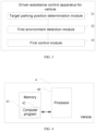
- FIG. 3 shows a schematic diagram of the structure of a driver-assistance control apparatus for a vehicle provided in an embodiment of the present application.
- the driver-assistance control apparatus for a vehicle includes:
- the driver-assistance control apparatus for a vehicle further includes: a second control module configured to redetermine the target parking position according to the data from the navigation system on the vehicle when the number of vehicles passing the target parking position within the first preset time is greater than or equal to the first preset value.
- the driver-assistance control apparatus for a vehicle further includes:
- the first control module 33 is further configured to:
- the first control module 33 is further configured to:
- the driver-assistance control apparatus for a vehicle further includes:
- the driver-assistance control apparatus for a vehicle further includes: an information sending module configured to send vehicle location information and vehicle status information to a preset contact.
- FIG. 4 is a schematic diagram of the structure of a vehicle provided in an embodiment of the present application.
- the vehicle 4 of this embodiment may include: at least one processor 40 (only one processor 40 is shown in FIG. 4 ), a memory 41, and a computer program 42 stored in the memory 41 and executable on the at least one processor 40.
- the processor 40 executes the computer program 42, the steps in any of the above-mentioned embodiments of the method are implemented, such as steps S101 to S103 in the embodiment shown in FIG. 1 .
- the processor 40 executes the computer program 42, the functions of each module/unit in the above-mentioned embodiments of the apparatus are implemented, such as the functions of modules 31 to 33 shown in FIG. 3 .
- the computer program 42 may be divided into one or more modules/units, which are stored in the memory 41 and executed by the processor 40 to implement the present invention.
- the one or more modules/units may be a series of computer program 42 instruction segments capable of implementing specific functions, which are used to describe the execution process of the computer program 42 in the vehicle 4.
- the embodiment of the present application further provides a computer-readable storage medium, which stores a computer program 42.
- the computer program 42 When executed by the processor 40, the computer program 42 causes the processor 40 to implement the steps in the above-mentioned method embodiments.
- An embodiment of the present application provides a computer program product.
- the computer program product runs on a mobile terminal
- the mobile terminal can implement the steps in the above-mentioned method embodiments when executing the computer program product.
- the integrated unit is implemented in the form of a software functional unit and sold or used as an independent product, it may be stored in a computer-readable storage medium.
- the present application implements all or part of the processes in the above-mentioned embodiment method, which can be completed by instructing the relevant hardware through a computer program 42.
- the computer program 42 may be stored in a computer-readable storage medium. When executed by the processor 40, the computer program 42 executes the steps of the above-mentioned various method embodiments.
- the computer program 42 includes computer program code, which can be in source code form, object code form, executable file, or some intermediate form.
- the computer-readable medium can at least include: any entity or device that can carry the computer program code to the terminal device, a recording medium, a computer memory, a read-only memory (ROM), a random access memory (RAM), an electric carrier signal, a telecommunication signal and a software distribution medium.
- a recording medium for example, a USB flash drive, a mobile hard disk, a magnetic disk, or an optical disk.
- ROM read-only memory
- RAM random access memory
- an electric carrier signal a telecommunication signal
- a software distribution medium for example, a USB flash drive, a mobile hard disk, a magnetic disk, or an optical disk.
- computer-readable media cannot be electric carrier signals and telecommunication signals.
- the disclosed devices/network equipment and methods can be implemented in other ways.
- the device/network equipment embodiments described above are merely schematic.
- the division of the modules or units is only a logical function division. There may be other division methods in actual implementation, such as multiple units or components can be combined or integrated into another system, or some features can be ignored or not executed.
- Another point is that the mutual coupling or direct coupling or communication connection shown or discussed can be through some interfaces, indirect coupling, or communication connection of devices or units, which can be electrical, mechanical, or other forms.
- the units described as separate components may or may not be physically separated, and the components shown as units may or may not be physical units, that is, they may be located in one place or distributed on multiple network units. Some or all of the units may be selected according to actual needs to achieve the purpose of the solution of this embodiment.
Landscapes
- Engineering & Computer Science (AREA)
- Mechanical Engineering (AREA)
- Physics & Mathematics (AREA)
- General Physics & Mathematics (AREA)
- Transportation (AREA)
- Automation & Control Theory (AREA)
- Human Computer Interaction (AREA)
- Thermal Sciences (AREA)
- Radar, Positioning & Navigation (AREA)
- Remote Sensing (AREA)
- Combustion & Propulsion (AREA)
- Mathematical Physics (AREA)
- Chemical & Material Sciences (AREA)
- Traffic Control Systems (AREA)
Abstract
Description
- This patent application claims priority to
Chinese patent application No. 202210018120.9 filed on January 7, 2022 - The present application relates to the field of vehicle technology, and in particular, to a driver-assistance control method and apparatus for a vehicle, a vehicle, and a storage medium.
- Fatigue driving refers to the physiological and psychological disorders of drivers after a long period of continuous driving, which objectively leads to a decline in driving skills and easily causes traffic accidents. During the driving process, when the driver is tired and needs to take a rest, the vehicle control system will show a recommended parking location for the driver to rest.
- However, the parking location recommended by the vehicle control system may have the problem of complex environment, resulting in the driver not being able to rest comfortably, or there may be potential safety hazards.
- An objective of the embodiments of the present application is to provide a driver-assistance control method and apparatus for a vehicle, a vehicle and a storage medium, which can solve the problem that the parking position recommended by the vehicle control system is not suitable for the driver to rest when the driver needs to take a rest.
- The technical solutions adopted in the embodiments of the present application are as follows.
- In a first aspect, a driver-assistance control method for a vehicle is provided, including:
- determining, when receiving a rest instruction, a target parking position based on data from a navigation system on the vehicle;
- counting, within a first preset time, the number of vehicles passing the target parking position when a distance between the vehicle and the target parking position is less than a preset distance; and
- controlling the vehicle to enter a driver rest mode when the number of vehicles passing the target parking position within the first preset time is less than a first preset value and the vehicle is parked at the target parking position.
- In a second aspect, a driver-assistance control apparatus for a vehicle is provided, including:
- a target parking position determination module, configured to determine a target parking position according to data from a navigation system on the vehicle when a rest instruction is received;
- a first environment detection module, configured to count the number of vehicles passing the target parking position within a first preset time when a distance between the vehicle and the target parking position is less than a preset distance; and
- a first control module, configured to control the vehicle to enter a driver rest mode when the number of vehicles passing the target parking position within the first preset time is less than a first preset value and the vehicle is parked at the target parking position.
- In a third aspect, a vehicle is provided, including a memory, a processor, and a computer program stored in the memory and executable on the processor. When executed by the processor, the computer program causes the processor to implement the driver-assistance control method for a vehicle as described in the first aspect.
- In a fourth aspect, a computer-readable storage medium is provided. The computer-readable storage medium stores a computer program, and when executed by a processor, the computer program causes the processor to implement the driver-assistance control method for a vehicle as described in the first aspect.
- The advantageous effects of the driver-assistance control method for a vehicle provided by the embodiments of the present application are that: when a rest instruction is received, it indicates that the driver needs to take a rest. At this moment, a target parking position is determined according to the data of the navigation system on the vehicle, and the driver can drive the vehicle to the target parking position. When the distance between the vehicle and the target parking position is less than the preset distance, the number of vehicles passing the target parking position is counted within the first preset time, and the traffic volume at the target parking position is detected before the vehicle reaches the target parking position. When the number of vehicles passing the target parking position within the first preset time is less than the first preset value, it indicates that the traffic volume at the target parking position is small, and the driver is less likely to be disturbed when resting. When the vehicle is parked at the target parking position, the vehicle is controlled to enter a driver rest mode, and the driver can rest comfortably and safely.
- It can be understood that the advantageous effects of the second to the fourth aspects mentioned above can be referred to the relevant description of the above-mentioned driver-assistance control method for a vehicle, and will not be repeated herein.
- In order to more clearly illustrate the technical solutions in the embodiments of the present application, the drawings used in the description of the embodiments or the exemplary technologies will be briefly introduced below. Apparently, the drawings described below are merely some embodiments of the present application. For one of ordinary skill in the art, other drawings can be obtained based on these drawings without any creative effort.
-
FIG. 1 is a flow chart of a driver-assistance control method for a vehicle provided in an embodiment of the present application; -
FIG. 2 is a flow chart of a driver-assistance control method for a vehicle provided in another embodiment of the present application; -
FIG. 3 is a schematic diagram of the structure of a driver-assistance control apparatus for a vehicle provided in an embodiment of the present application; and -
FIG. 4 is a schematic diagram of the structure of a vehicle provided in an embodiment of the present application. - In the following description, specific details such as specific system structures, technologies, and the like are provided for the purpose of explanation rather than limitation, so as to provide a thorough understanding of the embodiments of the present application. However, it should be understood by those skilled in the art that the present application may also be implemented in other embodiments without these specific details. In other cases, detailed descriptions of well-known systems, devices, circuits, and methods are omitted to prevent unnecessary details from obstructing the description of the present application.
- It should be understood that when used in the present specification and the appended claims, the term "comprises" indicates the presence of described features, integrals, steps, operations, elements and/or components, but does not exclude the presence or addition of one or more other features, integrals, steps, operations, elements, components and/or combinations thereof.
- It should also be understood that the term "and/or" used in the present specification and appended claims refers to and includes any and all possible combinations of one or more of the associated listed items.
- As used in the present specification and appended claims of this application, the term "if" may be interpreted as "when" or "once" or "in response to determining" or "in response to detecting", depending on the context. Similarly, the phrase "if determined" or "if [described condition or event] is detected" may be interpreted as meaning "once determined" or "in response to determining" or "once [described condition or event] is detected" or "in response to detecting [described condition or event]", depending on the context.
- In addition, in the description of the present specification and the appended claims of the application, the terms "first", "second", "third", and the like are only used to distinguish the descriptions and cannot be understood as indicating or implying relative importance.
- References to "one embodiment" or "some embodiments", or the like described in the specification of this application mean that one or more embodiments of the present application include specific features, structures or characteristics described in conjunction with the embodiment. Therefore, the statements "in one embodiment", "in some embodiments", "in some other embodiments", "in yet other embodiments", and the like that appear in different places in this specification do not necessarily refer to the same embodiment, but mean "one or more but not all embodiments ", unless otherwise specifically emphasized. The terms "including", "comprising", "having" and variations thereof all mean "including but not limited to", unless otherwise specifically emphasized.
-
FIG. 1 shows a schematic flow chart of a driver-assistance control method for a vehicle provided in an embodiment of the present application. Referring toFIG. 1 , the driver-assistance control method for a vehicle includes the following steps S101 to S103. - In step S101, a target parking position is determined according to data from a navigation system on the vehicle when a rest instruction is received.
- Specifically, if the driver becomes fatigued while driving the vehicle, the driver may send a rest instruction to the processor on the vehicle by voice or by operating buttons. When the processor receives the rest instruction, a target parking position is determined based on the data from the navigation system on the vehicle, and the determined target parking position is the position closest to the current position of the vehicle. After the target parking position is determined, the navigation system on the vehicle automatically plans a route to the target parking position so that the driver can drive the vehicle to the target parking position.
- In step S102: the number of vehicles passing the target parking position within a first preset time is counted when the distance between the vehicle and the target parking position is less than a preset distance.
- Specifically, after the target parking position is determined, the driver drives the vehicle to the target parking position. When the distance between the vehicle and the target parking position is less than a preset distance, the number of vehicles passing the target parking position is counted within the first preset time, and the traffic volume at the target parking position is detected in advance to determine whether the target parking position is suitable for the driver to rest. The number of vehicles passing the target parking position may be detected by the navigation system on the vehicle. Compared with detecting the traffic volume after the vehicle stops at the target parking position, detecting the traffic volume of the target parking position in advance can enable the driver to know in advance whether the target parking position meets their rest requirements. If the target parking position meets the rest requirements, the driver can quickly enter the rest state after parking the vehicle at the target parking position; if the target parking position does not meet the rest requirements, a new target parking position can be found in advance.
- It should be noted that the first preset time may be set according to actual conditions, for example, the preset time is set to 3 minutes, 5 minutes, 10 minutes, or the like. The preset distance may be set according to actual conditions, for example, the preset distance is set to 0.5 km, 1 km, 2 km, or the like.
- In step S103, the vehicle is controlled to enter a driver rest mode when the number of vehicles passing the target parking position within the first preset time is less than a first preset value, and the vehicle is parked at the target parking position.
- Specifically, when the number of vehicles passing the target parking position within the first preset time is less than the first preset value, it means that the traffic volume at the target parking position is low, and the driver is less likely to be disturbed when resting. After the vehicle is parked at the target parking position, the vehicle is controlled to enter the driver rest mode, and the driver can rest comfortably and safely.
- When the number of vehicles passing the target parking position within the first preset time is greater than or equal to the first preset value, it means that the traffic volume at the target parking position is high, and the driver taking rest at this position will be disturbed and unsafe. In this case, the vehicle processor will send an alarm message to remind the driver to change the parking position, re-determine the target parking position according to the data in the navigation system on the vehicle, and plan a new route to another target parking position so that the driver can go to a new target parking position.
- When the number of vehicles passing the target parking position within the first preset time is less than the first preset value, it indicates that the traffic volume at the target parking position is low, which can improve the safety of the driver when taking a rest.
- However, the noise at the target parking position will directly affect the comfort of the driver when resting. If the noise at the target parking position is too loud, the driver will not be able to rest comfortably. The best target parking position should be able to ensure both the safety and comfort of the driver when resting. Therefore, after completing the detection of the traffic volume at the target parking position, it is necessary to detect the noise level at the target parking position to further determine whether the location is suitable for the driver to rest.
-
FIG. 2 shows a schematic flow chart of a driver-assistance control method for a vehicle provided by another embodiment of the present application. Referring toFIG. 2 , the driver-assistance control method for a vehicle may further includestep S 104 and step S105. - In
step S 104, after the vehicle stops at the target parking position, the number of times the noise level at the target parking position is greater than a preset decibel is counted within a second preset time. - Specifically, after the vehicle stops at the target parking position, the number of times the noise level at the target parking position is greater than the preset decibel is counted within the second preset time. The noise level may be collected by a sound collector inside the vehicle. Noises at the preset decibel will affect the normal rest of the driver, and the preset decibel may be set according to actual needs.
- It should be noted that the second preset time may be set according to actual conditions, for example, the preset time may be set to 1 minute, 2 minutes, 5 minutes, or the like.
- In step S105, when the number of times that the noise level at the target parking position is greater than the preset decibel within the second preset time is less than a second preset value, and the number of vehicles passing the target parking position within the first preset time is less than the first preset value, the vehicle is controlled to enter the driver rest mode.
- Specifically, when the number of times that the noise level at the target parking position is greater than the preset decibel within the second preset time is less than the second preset value, it means that the noise at the target parking position is relatively low and will not affect the driver when resting, or has a small impact on the driver when resting. When the number of times that the noise level at the target parking position is greater than the preset decibel within the second preset time is less than the second preset value, and the number of vehicles passing the target parking position within the first preset time is less than the first preset value, it means that the traffic volume at the target parking position is low and quiet, which is suitable for the driver to rest. Accordingly, the vehicle is controlled to enter the driver rest mode, and the driver can rest comfortably.
- If the number of times that the noise level of the target parking position is greater than the preset decibel within the second preset time is greater than or equal to the second preset value, it indicates that the noise at the target parking position is relatively large and will affect the driver's rest. As a result, the target parking position is re-determined according to the data from the vehicle navigation system, and a new route to another target parking position is planned so that the driver can go to the new target parking position.
- When the traffic volume and noise level at the target parking position meet the conditions, the driver can take a rest at the target parking position. In order to improve the comfort of the driver when resting, the environment where the driver is located needs to be controlled so as to further improve the comfort of the driver.
- Therefore, controlling the vehicle to enter the driver rest mode in step S103 includes step S1031 and step S1032.
- In step S1031, the temperature, humidity, and oxygen concentration in the vehicle compartment are measured.
- Specifically, the temperature sensor in the vehicle compartment may collect the temperature data and transmit the collected temperature to the processor on the vehicle. The humidity sensor in the vehicle compartment can collect humidity data and transmit the collected humidity to the processor on the vehicle. The oxygen concentration sensor in the vehicle compartment can collect oxygen concentration and transmit the collected oxygen concentration to the processor on the vehicle. Thus, the processor on the vehicle completes the acquisition of the temperature, humidity and oxygen concentration in the vehicle.
- In step S 1032, according to the temperature, humidity and oxygen concentration, an air-conditioning system is controlled to operate so that the temperature is within a preset temperature range, the humidity is within a preset humidity range, and the oxygen concentration is within a preset concentration range.
- Specifically, after the processor on the vehicle obtains the temperature, humidity and oxygen concentration inside the vehicle, it controls the operation of the air-conditioning system and regulates the temperature, humidity and oxygen concentration inside the vehicle so that the temperature is within the preset temperature range, the humidity is within the preset humidity range, and the oxygen concentration is within the preset concentration range, thereby improving the comfort of the environment for the driver to rest.
- When the driver is taking a rest, moving objects around the target parking position may collide with the vehicle, which may cause safety hazards to the personal safety or property safety of the driver. When the driver is taking a rest, objects around the vehicle are monitored to improve the safety of the personal and property safety of the driver. Therefore, controlling the vehicle to enter the driver rest mode in
step S 103 includes steps S 1033 to S 1035. - In step S1033, image information, speed information and movement direction information of objects around the vehicle are acquired.
- Specifically, when the driver starts to rest, the camera on the vehicle can collect image information of objects around the vehicle, and the radar on the vehicle can collect speed information and movement direction information of the objects around the vehicle.
- In step S1033, it is determined whether the object has a risk of colliding with the vehicle based on the image information, speed information and movement direction information.
- Specifically, by analyzing the image information of the object, the type of the object can be known, for example, whether the object is a car, a bicycle, or a truck. The moving trajectory of the object may be analyzed by the speed information and movement direction information of the object. Combining the image information, speed information and movement direction information of the object, it can be analyzed whether the object has a risk of colliding with the vehicle.
- For example, when the object is a truck, and the truck is traveling toward the target parking position and the driving speed is too fast (for example, 50 km/h), it is determined that the truck may collide with the vehicle.
- In step S1033, when it is determined that the object has a risk of colliding with the vehicle, an alarm message is sent.
- Specifically, when it is determined that an object has a risk of colliding with the vehicle, the alarm on the vehicle is controlled to send an alarm message to remind the driver who is taking a rest, so that the driver can take measures in advance to prevent the danger of a collision and ensure the safety of the driver.
- In addition, the image information of objects around the vehicle is collected to achieve the monitoring function. When the processor determines that the vehicle is in a stolen state through image information analysis, the alarm is controlled to send an alarm message to remind the driver, which can prevent robbery. When robbery occurs, evidence can be found in the stored image information, facilitating the police to solve the case in time.
- In one embodiment of the present application, after step S102, the method further includes steps S106 to S 108.
- In step S106, a preset sleep time is obtained.
- Specifically, the preset sleep time may be set according to the actual needs of the driver, and the driver may set the preset sleep time by voice or by operating the control panel.
- In addition, when the vehicle enters the driver rest mode, the parking lights on the vehicle are controlled to light up, which can warn passing vehicles, prevent passing vehicles from colliding with the vehicle, and improve the safety of the driver when resting.
- In step S107, when the vehicle enters the driver rest mode, the duration of the vehicle being in the driver rest mode is timed.
- In step S108, when the duration of the vehicle in the driver rest mode reaches a preset sleep time, a wake-up message is sent to wake up the driver.
- Specifically, the driver can set a preset sleep time for an automatic wake-up function for the driver, thereby preventing the driver from oversleeping and improving the intelligence of the vehicle for the driver to rest.
- When the traffic volume and noise at the target parking position meet the requirements, the safety and comfort of the driver can be improved when resting. However, accidents cannot be guaranteed when the driver is resting. Therefore, when the vehicle enters the driver rest mode, the vehicle location information and vehicle status information are sent to a preset contact.
- Specifically, the preset contact may be a relative or friend of the driver, and the preset contact will know the driver's current location and vehicle status through the vehicle location information and vehicle status information. When the driver encounters an accident, the preset contact can quickly locate the driver through the vehicle location information and vehicle status information, so as to provide timely rescue to the driver.
- It should be understood that the size of the serial numbers of the steps in the above embodiments does not mean the order of execution. The execution order of each process should be determined by its function and internal logic, and should not constitute any limitation on the implementation process of the embodiments of the present application.
-
FIG. 3 shows a schematic diagram of the structure of a driver-assistance control apparatus for a vehicle provided in an embodiment of the present application. Referring toFIG. 3 , the driver-assistance control apparatus for a vehicle includes: - a target parking
position determination module 31, configured to determine the target parking position according to data from a navigation system on the vehicle when receiving a rest instruction; - a first
environment detection module 32, configured to count the number of vehicles passing the target parking position within a first preset time when a distance between the vehicle and the target parking position is less than a preset distance; and - a
first control module 33, configured to control the vehicle to enter a driver rest mode when the number of vehicles passing the target parking position within the first preset time is less than a first preset value and the vehicle is parked at the target parking position. - In one embodiment of the present application, the driver-assistance control apparatus for a vehicle further includes:
a second control module configured to redetermine the target parking position according to the data from the navigation system on the vehicle when the number of vehicles passing the target parking position within the first preset time is greater than or equal to the first preset value. - In one embodiment of the present application, the driver-assistance control apparatus for a vehicle further includes:
- a second environment detection module configured to count the number of times that noise level at the target parking position is greater than a preset decibel within a second preset time after the vehicle is parked at the target parking position; and
- a third control module configured to control the vehicle to enter a driver rest mode when the number of times the noise level at the target parking position is greater than the preset decibel within the second preset time is less than a second preset value, and the number of vehicles passing the target parking position within the first preset time is less than the first preset value.
- In one embodiment of the present application, the
first control module 33 is further configured to: - obtain the temperature, humidity and oxygen concentration in a vehicle compartment; and
- the air-conditioning system is controlled to operate, according to the temperature, the humidity and the oxygen concentration, so that the temperature is within a preset temperature range, the humidity is within a preset humidity range, and the oxygen concentration is within a preset concentration range.
- In one embodiment of the present application, the
first control module 33 is further configured to: - acquire an image information, a speed information, and a movement direction information of an object around the vehicle;
- determine, based on the image information, the speed information, and the movement direction information, whether the object has a risk of colliding with the vehicle; and
- send an alarm message when the object is determined to have a risk of colliding with the vehicle.
- In one embodiment of the present application, the driver-assistance control apparatus for a vehicle further includes:
- a preset sleep time acquisition module configured to acquire the preset sleep time;
- a timing module, configured to time a duration of the vehicle being in the driver rest mode after the vehicle enters the driver rest mode;
- a wake-up module configured to send a wake-up message to wake up the driver when the duration of the vehicle being in the driver rest mode reaches the preset sleep time.
- In one embodiment of the present application, the driver-assistance control apparatus for a vehicle further includes:
an information sending module configured to send vehicle location information and vehicle status information to a preset contact. - It is clear to those skilled in the art that, for the ease description and brevity, only the division of the above-mentioned functional units and modules is used as an example for illustration. In practical applications, the above-mentioned function allocation can be completed by different functional units and modules as needed, that is, the internal structure of the device can be divided into different functional units or modules to complete all or part of the functions described above. The functional units and modules in the embodiment can be integrated into a processing unit, or each unit can exist physically separately, or two or more units can be integrated into one unit. The above-mentioned integrated unit can be implemented in the form of hardware or in the form of software functional units. In addition, the specific names of the functional units and modules are only for the convenience of distinguishing each other, and are not intended to limit the scope of protection of this application. The specific working process of the units and modules in the above-mentioned system can be referred to the corresponding process in the aforementioned method embodiments, which will not be repeated herein.
-
FIG. 4 is a schematic diagram of the structure of a vehicle provided in an embodiment of the present application. As shown inFIG. 4 , the vehicle 4 of this embodiment may include: at least one processor 40 (only oneprocessor 40 is shown inFIG. 4 ), amemory 41, and acomputer program 42 stored in thememory 41 and executable on the at least oneprocessor 40. When theprocessor 40 executes thecomputer program 42, the steps in any of the above-mentioned embodiments of the method are implemented, such as steps S101 to S103 in the embodiment shown inFIG. 1 . Alternatively, when theprocessor 40 executes thecomputer program 42, the functions of each module/unit in the above-mentioned embodiments of the apparatus are implemented, such as the functions ofmodules 31 to 33 shown inFIG. 3 . - Exemplarily, the
computer program 42 may be divided into one or more modules/units, which are stored in thememory 41 and executed by theprocessor 40 to implement the present invention. The one or more modules/units may be a series ofcomputer program 42 instruction segments capable of implementing specific functions, which are used to describe the execution process of thecomputer program 42 in the vehicle 4. - The embodiment of the present application further provides a computer-readable storage medium, which stores a
computer program 42. When executed by theprocessor 40, thecomputer program 42 causes theprocessor 40 to implement the steps in the above-mentioned method embodiments. - An embodiment of the present application provides a computer program product. When the computer program product runs on a mobile terminal, the mobile terminal can implement the steps in the above-mentioned method embodiments when executing the computer program product.
- If the integrated unit is implemented in the form of a software functional unit and sold or used as an independent product, it may be stored in a computer-readable storage medium. Based on this understanding, the present application implements all or part of the processes in the above-mentioned embodiment method, which can be completed by instructing the relevant hardware through a
computer program 42. Thecomputer program 42 may be stored in a computer-readable storage medium. When executed by theprocessor 40, thecomputer program 42 executes the steps of the above-mentioned various method embodiments. Thecomputer program 42 includes computer program code, which can be in source code form, object code form, executable file, or some intermediate form. The computer-readable medium can at least include: any entity or device that can carry the computer program code to the terminal device, a recording medium, a computer memory, a read-only memory (ROM), a random access memory (RAM), an electric carrier signal, a telecommunication signal and a software distribution medium. For example, a USB flash drive, a mobile hard disk, a magnetic disk, or an optical disk. In some jurisdictions, according to legislation and patent practice, computer-readable media cannot be electric carrier signals and telecommunication signals. - In the above embodiments, the description of each embodiment has its own focus. For parts that are not described or recorded in detail in a certain embodiment, reference can be made to the relevant descriptions of other embodiments.
- Those of ordinary skill in the art will appreciate that the units and algorithm steps of each example described in conjunction with the embodiments disclosed herein can be implemented in electronic hardware, or a combination of computer software and electronic hardware. Whether these functions are performed in hardware or software depends on the specific application and design constraints of the technical solution. The skilled person can use different methods to implement the described functions for each specific application, but such implementation should not be considered to be beyond the scope of this application.
- In the embodiments provided in the present application, it should be understood that the disclosed devices/network equipment and methods can be implemented in other ways. For example, the device/network equipment embodiments described above are merely schematic. For example, the division of the modules or units is only a logical function division. There may be other division methods in actual implementation, such as multiple units or components can be combined or integrated into another system, or some features can be ignored or not executed. Another point is that the mutual coupling or direct coupling or communication connection shown or discussed can be through some interfaces, indirect coupling, or communication connection of devices or units, which can be electrical, mechanical, or other forms.
- The units described as separate components may or may not be physically separated, and the components shown as units may or may not be physical units, that is, they may be located in one place or distributed on multiple network units. Some or all of the units may be selected according to actual needs to achieve the purpose of the solution of this embodiment.
- The embodiments described above are only used to illustrate the technical solutions of the present application, rather than to limit them. Although the present application has been described in detail with reference to the aforementioned embodiments, those skilled in the art should understand that the technical solutions described in the aforementioned embodiments may still be modified, or some of the technical features may be substituted by equivalents. Such modifications or replacements do not deviate the essence of the corresponding technical solutions from the spirit and scope of the technical solutions of the embodiments of the present application, and should all be included in the scope of protection of the present application.
Claims (12)
- A driver-assistance control method for a vehicle, characterized by comprising:determining, when receiving a rest instruction, a target parking position based on data from a navigation system on the vehicle;counting, within a first preset time, the number of vehicles passing the target parking position when a distance between the vehicle and the target parking position is less than a preset distance; andcontrolling the vehicle to enter a driver rest mode when the number of vehicles passing the target parking position within the first preset time is less than a first preset value and the vehicle is parked at the target parking position.
- The driver-assistance control method for a vehicle according to claim 1, characterized in that the driver-assistance control method for a vehicle further comprises:
re-determining a target parking position according to the data from the navigation system on the vehicle when the number of vehicles passing the target parking position within the first preset time is greater than or equal to the first preset value. - The driver-assistance control method for a vehicle according to claim 2, characterized in that the driver-assistance control method for a vehicle further comprises:
sending an alarm message to remind the driver to change a parking position when the number of vehicles passing the target parking position within the first preset time is greater than or equal to the first preset value. - The driver-assistance control method for a vehicle according to claim 1, characterized in that the driver-assistance control method for a vehicle further comprises:counting the number of times that a noise level at the target parking position is greater than a preset decibel within a second preset time after the vehicle is parked at the target parking position; andcontrolling the vehicle to enter the driver rest mode when the number of times that the noise level at the target parking position is greater than the preset decibel within the second preset time is less than a second preset value, and the number of vehicles passing the target parking position within the first preset time is less than the first preset value.
- The driver-assistance control method for a vehicle according to claim 4, characterized in that the driver-assistance control method for a vehicle further comprises:
re-determining a target parking position according to the data from the navigation system on the vehicle when the number of times that the noise level at the target parking position is greater than the preset decibel within the second preset time is greater than or equal to the second preset value. - The driver-assistance control method for a vehicle according to any one of claims 1 to 5, characterized in that the step of controlling the vehicle to enter a driver rest mode comprises:acquiring a temperature, a humidity and an oxygen concentration in a vehicle compartment; andcontrolling an air-conditioning system to operate according to the temperature, the humidity and the oxygen concentration, so that the temperature is within a preset temperature range, the humidity is within a preset humidity range, and the oxygen concentration is within a preset concentration range.
- The driver-assistance control method for a vehicle according to claim 6, characterized in that the step of controlling the vehicle to enter a driver rest mode further comprises:acquiring image information, speed information, and movement direction information of an object around the vehicle;determining, based on the image information, the speed information, and the movement direction information, whether the object has a risk of colliding with the vehicle; andsending an alarm message when the object is determined to have the risk of colliding with the vehicle.
- The driver-assistance control method for a vehicle according to any one of claims 1 to 5, characterized in that, after the vehicle is parked at the target parking position, the method further comprises:obtaining a preset sleep time;timing, when the vehicle enters the driver rest mode, the duration of the vehicle being in the driver rest mode; andsending a wake-up message to wake up the driver when the duration of the vehicle being in the driver rest mode reaches the preset sleep time.
- The driver-assistance control method for a vehicle according to any one of claims 1 to 5, characterized in that, after the vehicle enters the driver rest mode, the method further comprises:
sending vehicle location information and vehicle status information to a preset contact. - A driver-assistance control apparatus for a vehicle, comprising:a target parking position determination module, configured to determine a target parking position according to data from a navigation system on the vehicle when a rest instruction is received;a first environment detection module, configured to count the number of vehicles passing the target parking position within a first preset time when a distance between the vehicle and the target parking position is less than a preset distance; anda first control module, configured to control the vehicle to enter a driver rest mode when the number of vehicles passing the target parking position within the first preset time is less than a first preset value and the vehicle is parked at the target parking position.
- A vehicle, comprising a memory, a processor, and a computer program stored in the memory and executable on the processor, wherein when executed by the processor, the computer program causes the processor to implement the driver-assistance control method for a vehicle according to any one of claims 1 to 9.
- A computer-readable storage medium storing a computer program, wherein when executed by a processor, the computer program causes the processor to implement the driver-assistance control method for a vehicle according to any one of claims 1 to 9.
Applications Claiming Priority (2)
| Application Number | Priority Date | Filing Date | Title |
|---|---|---|---|
| CN202210018120.9A CN115116260B (en) | 2022-01-07 | 2022-01-07 | Vehicle driving assistance control method, device and vehicle |
| PCT/CN2023/070930 WO2023131278A1 (en) | 2022-01-07 | 2023-01-06 | Vehicle driving assistance control method and apparatus, and vehicle and storage medium |
Publications (3)
| Publication Number | Publication Date |
|---|---|
| EP4462405A1 true EP4462405A1 (en) | 2024-11-13 |
| EP4462405A4 EP4462405A4 (en) | 2025-04-09 |
| EP4462405B1 EP4462405B1 (en) | 2026-03-11 |
Family
ID=83324830
Family Applications (1)
| Application Number | Title | Priority Date | Filing Date |
|---|---|---|---|
| EP23737140.6A Active EP4462405B1 (en) | 2022-01-07 | 2023-01-06 | Vehicle driving assistance control method and apparatus, and vehicle and storage medium |
Country Status (3)
| Country | Link |
|---|---|
| EP (1) | EP4462405B1 (en) |
| CN (1) | CN115116260B (en) |
| WO (1) | WO2023131278A1 (en) |
Families Citing this family (2)
| Publication number | Priority date | Publication date | Assignee | Title |
|---|---|---|---|---|
| CN115116260B (en) * | 2022-01-07 | 2024-07-12 | 长城汽车股份有限公司 | Vehicle driving assistance control method, device and vehicle |
| CN117935434A (en) * | 2024-01-29 | 2024-04-26 | 东莞市艾慕寝室用品有限公司 | Sofa-based massage method and device, electronic equipment and storage medium |
Family Cites Families (16)
| Publication number | Priority date | Publication date | Assignee | Title |
|---|---|---|---|---|
| CN201769737U (en) * | 2010-06-24 | 2011-03-23 | 杜少杰 | Automatic rest prompting device used in automobile driving |
| CN101916495B (en) * | 2010-08-19 | 2012-12-19 | 北京中交兴路信息科技有限公司 | Vehicle DAS (Driver Assistant System) and method |
| JP5967116B2 (en) * | 2014-02-27 | 2016-08-10 | 株式会社デンソー | In-vehicle system, information processing apparatus, and program |
| US9688220B2 (en) * | 2014-06-18 | 2017-06-27 | GM Global Technology Operations LLC | Vehicle apparatus control from rear seat |
| CN105242862A (en) * | 2015-10-29 | 2016-01-13 | 广东好帮手电子科技股份有限公司 | Vehicle-mounted terminal with simple operation mode and operation method of vehicle-mounted terminal |
| CN107200022B (en) * | 2016-03-15 | 2019-11-12 | 奥迪股份公司 | Driving assistance system and method |
| US10214240B2 (en) * | 2017-04-20 | 2019-02-26 | GM Global Technology Operations LLC | Parking scoring for autonomous vehicles |
| CN107248315A (en) * | 2017-06-21 | 2017-10-13 | 深圳市盛路物联通讯技术有限公司 | The commending system and method in a kind of parking navigation path |
| CN108238053A (en) * | 2017-12-15 | 2018-07-03 | 北京车和家信息技术有限公司 | A kind of vehicle drive monitoring method, device and vehicle |
| JP6970011B2 (en) * | 2017-12-27 | 2021-11-24 | トヨタ自動車株式会社 | Environmental adjustment system, environmental adjustment method and environmental adjustment program |
| CN112767729A (en) * | 2019-10-17 | 2021-05-07 | 杭州小旅科技有限公司 | Intelligent parking lot management system and method |
| CN112776733A (en) * | 2019-11-08 | 2021-05-11 | 上海博泰悦臻电子设备制造有限公司 | Method, system, medium and equipment for realizing in-vehicle leisure based on self-learning |
| CN111391858A (en) * | 2020-02-18 | 2020-07-10 | 吉利汽车研究院(宁波)有限公司 | Intelligent cabin system control method and system and automobile |
| CN111627131A (en) * | 2020-04-28 | 2020-09-04 | 南京理工大学 | Driving recording device and method with driver auxiliary monitoring warning function |
| CN113345204B (en) * | 2021-05-27 | 2022-07-01 | 云度新能源汽车有限公司 | Vehicle-mounted remote fatigue awakening method and awakening system thereof |
| CN115116260B (en) * | 2022-01-07 | 2024-07-12 | 长城汽车股份有限公司 | Vehicle driving assistance control method, device and vehicle |
-
2022
- 2022-01-07 CN CN202210018120.9A patent/CN115116260B/en active Active
-
2023
- 2023-01-06 EP EP23737140.6A patent/EP4462405B1/en active Active
- 2023-01-06 WO PCT/CN2023/070930 patent/WO2023131278A1/en not_active Ceased
Also Published As
| Publication number | Publication date |
|---|---|
| WO2023131278A1 (en) | 2023-07-13 |
| EP4462405B1 (en) | 2026-03-11 |
| CN115116260A (en) | 2022-09-27 |
| EP4462405A4 (en) | 2025-04-09 |
| CN115116260B (en) | 2024-07-12 |
Similar Documents
| Publication | Publication Date | Title |
|---|---|---|
| EP3882098B1 (en) | Information processing apparatus, vehicle, and method, and program | |
| US9776644B2 (en) | On-vehicle situation detection apparatus and method | |
| EP2513882B1 (en) | A predictive human-machine interface using eye gaze technology, blind spot indicators and driver experience | |
| EP3182392A1 (en) | Driving fatigue early warning method and system for use in vehicle | |
| CN112572456A (en) | Driver driving behavior reminding system and method and automobile | |
| JP2016115356A (en) | Automatic drive control device, automatic drive control method, and program | |
| CN111231969A (en) | A kind of vehicle driving state detection method | |
| EP4462405B1 (en) | Vehicle driving assistance control method and apparatus, and vehicle and storage medium | |
| JP2014181020A (en) | Travel control device | |
| JPH08178712A (en) | Ambush driving detector | |
| CN107832748A (en) | A kind of shared automobile driver changes system and method | |
| JP5712712B2 (en) | In-vehicle function controller | |
| JP2016181032A (en) | Automatic travel control device and automatic travel control system | |
| KR20220014945A (en) | System and method for monitering driver | |
| CN118343051A (en) | System and method for preventing interaction between a vehicle and a moving object | |
| CN117416375A (en) | Vehicle avoidance methods, devices, equipment and storage media | |
| CN113879313A (en) | Driver fatigue detection method and device | |
| CN118082856A (en) | Assisted driving method and terminal | |
| CN110155007A (en) | Brake control method, mobile unit and the braking control device of vehicle | |
| CN112141094A (en) | Vehicle and anti-collision method and device thereof | |
| JP7703853B2 (en) | Vehicle control device, vehicle control method and program | |
| CN112926545A (en) | Vehicle-mounted emergency braking dangerous behavior recognition system, control method and storage medium | |
| CN219115336U (en) | Personal information protection system and vehicle with same | |
| CN117605372A (en) | Vehicle door opening anti-collision control method, device, equipment and medium | |
| CN116513040A (en) | Automatic control method, system, equipment and storage medium for vehicle whistle |
Legal Events
| Date | Code | Title | Description |
|---|---|---|---|
| STAA | Information on the status of an ep patent application or granted ep patent |
Free format text: STATUS: THE INTERNATIONAL PUBLICATION HAS BEEN MADE |
|
| PUAI | Public reference made under article 153(3) epc to a published international application that has entered the european phase |
Free format text: ORIGINAL CODE: 0009012 |
|
| STAA | Information on the status of an ep patent application or granted ep patent |
Free format text: STATUS: REQUEST FOR EXAMINATION WAS MADE |
|
| 17P | Request for examination filed |
Effective date: 20240805 |
|
| AK | Designated contracting states |
Kind code of ref document: A1 Designated state(s): AL AT BE BG CH CY CZ DE DK EE ES FI FR GB GR HR HU IE IS IT LI LT LU LV MC ME MK MT NL NO PL PT RO RS SE SI SK SM TR |
|
| A4 | Supplementary search report drawn up and despatched |
Effective date: 20250312 |
|
| RIC1 | Information provided on ipc code assigned before grant |
Ipc: G08G 1/0968 20060101ALI20250306BHEP Ipc: G08G 1/14 20060101AFI20250306BHEP |
|
| DAV | Request for validation of the european patent (deleted) | ||
| DAX | Request for extension of the european patent (deleted) | ||
| GRAP | Despatch of communication of intention to grant a patent |
Free format text: ORIGINAL CODE: EPIDOSNIGR1 |
|
| STAA | Information on the status of an ep patent application or granted ep patent |
Free format text: STATUS: GRANT OF PATENT IS INTENDED |
|
| RIC1 | Information provided on ipc code assigned before grant |
Ipc: G08G 1/14 20060101AFI20251104BHEP Ipc: G08G 1/0968 20060101ALI20251104BHEP Ipc: B60W 40/02 20060101ALI20251104BHEP Ipc: B60W 50/14 20200101ALI20251104BHEP Ipc: B62D 15/02 20060101ALI20251104BHEP |
|
| INTG | Intention to grant announced |
Effective date: 20251126 |
|
| GRAS | Grant fee paid |
Free format text: ORIGINAL CODE: EPIDOSNIGR3 |
|
| GRAA | (expected) grant |
Free format text: ORIGINAL CODE: 0009210 |
|
| STAA | Information on the status of an ep patent application or granted ep patent |
Free format text: STATUS: THE PATENT HAS BEEN GRANTED |
|
| AK | Designated contracting states |
Kind code of ref document: B1 Designated state(s): AL AT BE BG CH CY CZ DE DK EE ES FI FR GB GR HR HU IE IS IT LI LT LU LV MC ME MK MT NL NO PL PT RO RS SE SI SK SM TR |
|
| REG | Reference to a national code |
Ref country code: CH Ref legal event code: F10 Free format text: ST27 STATUS EVENT CODE: U-0-0-F10-F00 (AS PROVIDED BY THE NATIONAL OFFICE) Effective date: 20260311 Ref country code: GB Ref legal event code: FG4D |
|
| REG | Reference to a national code |
Ref country code: DE Ref legal event code: R096 Ref document number: 602023013472 Country of ref document: DE |
|
| REG | Reference to a national code |
Ref country code: IE Ref legal event code: FG4D |
|
| P01 | Opt-out of the competence of the unified patent court (upc) registered |
Free format text: CASE NUMBER: UPC_APP_0009162_4462405/2026 Effective date: 20260309 |