EP4462033A1 - Water system - Google Patents
Water system Download PDFInfo
- Publication number
- EP4462033A1 EP4462033A1 EP24732375.1A EP24732375A EP4462033A1 EP 4462033 A1 EP4462033 A1 EP 4462033A1 EP 24732375 A EP24732375 A EP 24732375A EP 4462033 A1 EP4462033 A1 EP 4462033A1
- Authority
- EP
- European Patent Office
- Prior art keywords
- pipe
- water
- tank
- water boiling
- valve
- Prior art date
- Legal status (The legal status is an assumption and is not a legal conclusion. Google has not performed a legal analysis and makes no representation as to the accuracy of the status listed.)
- Pending
Links
Images




Classifications
-
- F—MECHANICAL ENGINEERING; LIGHTING; HEATING; WEAPONS; BLASTING
- F24—HEATING; RANGES; VENTILATING
- F24D—DOMESTIC- OR SPACE-HEATING SYSTEMS, e.g. CENTRAL HEATING SYSTEMS; DOMESTIC HOT-WATER SUPPLY SYSTEMS; ELEMENTS OR COMPONENTS THEREFOR
- F24D17/00—Domestic hot-water supply systems
- F24D17/02—Domestic hot-water supply systems using heat pumps
-
- F—MECHANICAL ENGINEERING; LIGHTING; HEATING; WEAPONS; BLASTING
- F24—HEATING; RANGES; VENTILATING
- F24D—DOMESTIC- OR SPACE-HEATING SYSTEMS, e.g. CENTRAL HEATING SYSTEMS; DOMESTIC HOT-WATER SUPPLY SYSTEMS; ELEMENTS OR COMPONENTS THEREFOR
- F24D19/00—Details
- F24D19/10—Arrangement or mounting of control or safety devices
- F24D19/1006—Arrangement or mounting of control or safety devices for water heating systems
- F24D19/1051—Arrangement or mounting of control or safety devices for water heating systems for domestic hot water
- F24D19/1054—Arrangement or mounting of control or safety devices for water heating systems for domestic hot water the system uses a heat pump
-
- F—MECHANICAL ENGINEERING; LIGHTING; HEATING; WEAPONS; BLASTING
- F24—HEATING; RANGES; VENTILATING
- F24H—FLUID HEATERS, e.g. WATER OR AIR HEATERS, HAVING HEAT-GENERATING MEANS, e.g. HEAT PUMPS, IN GENERAL
- F24H15/00—Control of fluid heaters
- F24H15/10—Control of fluid heaters characterised by the purpose of the control
- F24H15/174—Supplying heated water with desired temperature or desired range of temperature
-
- F—MECHANICAL ENGINEERING; LIGHTING; HEATING; WEAPONS; BLASTING
- F24—HEATING; RANGES; VENTILATING
- F24H—FLUID HEATERS, e.g. WATER OR AIR HEATERS, HAVING HEAT-GENERATING MEANS, e.g. HEAT PUMPS, IN GENERAL
- F24H15/00—Control of fluid heaters
- F24H15/20—Control of fluid heaters characterised by control inputs
- F24H15/212—Temperature of the water
- F24H15/223—Temperature of the water in the water storage tank
-
- F—MECHANICAL ENGINEERING; LIGHTING; HEATING; WEAPONS; BLASTING
- F24—HEATING; RANGES; VENTILATING
- F24H—FLUID HEATERS, e.g. WATER OR AIR HEATERS, HAVING HEAT-GENERATING MEANS, e.g. HEAT PUMPS, IN GENERAL
- F24H15/00—Control of fluid heaters
- F24H15/20—Control of fluid heaters characterised by control inputs
- F24H15/281—Input from user
-
- F—MECHANICAL ENGINEERING; LIGHTING; HEATING; WEAPONS; BLASTING
- F24—HEATING; RANGES; VENTILATING
- F24H—FLUID HEATERS, e.g. WATER OR AIR HEATERS, HAVING HEAT-GENERATING MEANS, e.g. HEAT PUMPS, IN GENERAL
- F24H15/00—Control of fluid heaters
- F24H15/30—Control of fluid heaters characterised by control outputs; characterised by the components to be controlled
- F24H15/305—Control of valves
- F24H15/315—Control of valves of mixing valves
-
- F—MECHANICAL ENGINEERING; LIGHTING; HEATING; WEAPONS; BLASTING
- F24—HEATING; RANGES; VENTILATING
- F24H—FLUID HEATERS, e.g. WATER OR AIR HEATERS, HAVING HEAT-GENERATING MEANS, e.g. HEAT PUMPS, IN GENERAL
- F24H15/00—Control of fluid heaters
- F24H15/30—Control of fluid heaters characterised by control outputs; characterised by the components to be controlled
- F24H15/305—Control of valves
- F24H15/32—Control of valves of switching valves
-
- F—MECHANICAL ENGINEERING; LIGHTING; HEATING; WEAPONS; BLASTING
- F24—HEATING; RANGES; VENTILATING
- F24H—FLUID HEATERS, e.g. WATER OR AIR HEATERS, HAVING HEAT-GENERATING MEANS, e.g. HEAT PUMPS, IN GENERAL
- F24H15/00—Control of fluid heaters
- F24H15/30—Control of fluid heaters characterised by control outputs; characterised by the components to be controlled
- F24H15/335—Control of pumps, e.g. on-off control
-
- F—MECHANICAL ENGINEERING; LIGHTING; HEATING; WEAPONS; BLASTING
- F24—HEATING; RANGES; VENTILATING
- F24H—FLUID HEATERS, e.g. WATER OR AIR HEATERS, HAVING HEAT-GENERATING MEANS, e.g. HEAT PUMPS, IN GENERAL
- F24H15/00—Control of fluid heaters
- F24H15/30—Control of fluid heaters characterised by control outputs; characterised by the components to be controlled
- F24H15/375—Control of heat pumps
-
- F—MECHANICAL ENGINEERING; LIGHTING; HEATING; WEAPONS; BLASTING
- F24—HEATING; RANGES; VENTILATING
- F24H—FLUID HEATERS, e.g. WATER OR AIR HEATERS, HAVING HEAT-GENERATING MEANS, e.g. HEAT PUMPS, IN GENERAL
- F24H15/00—Control of fluid heaters
- F24H15/40—Control of fluid heaters characterised by the type of controllers
- F24H15/414—Control of fluid heaters characterised by the type of controllers using electronic processing, e.g. computer-based
- F24H15/421—Control of fluid heaters characterised by the type of controllers using electronic processing, e.g. computer-based using pre-stored data
- F24H15/429—Control of fluid heaters characterised by the type of controllers using electronic processing, e.g. computer-based using pre-stored data for selecting operation modes
-
- F—MECHANICAL ENGINEERING; LIGHTING; HEATING; WEAPONS; BLASTING
- F24—HEATING; RANGES; VENTILATING
- F24H—FLUID HEATERS, e.g. WATER OR AIR HEATERS, HAVING HEAT-GENERATING MEANS, e.g. HEAT PUMPS, IN GENERAL
- F24H15/00—Control of fluid heaters
- F24H15/40—Control of fluid heaters characterised by the type of controllers
- F24H15/414—Control of fluid heaters characterised by the type of controllers using electronic processing, e.g. computer-based
- F24H15/45—Control of fluid heaters characterised by the type of controllers using electronic processing, e.g. computer-based remotely accessible
-
- F—MECHANICAL ENGINEERING; LIGHTING; HEATING; WEAPONS; BLASTING
- F24—HEATING; RANGES; VENTILATING
- F24H—FLUID HEATERS, e.g. WATER OR AIR HEATERS, HAVING HEAT-GENERATING MEANS, e.g. HEAT PUMPS, IN GENERAL
- F24H9/00—Details
- F24H9/12—Arrangements for connecting heaters to circulation pipes
- F24H9/13—Arrangements for connecting heaters to circulation pipes for water heaters
- F24H9/133—Storage heaters
-
- F—MECHANICAL ENGINEERING; LIGHTING; HEATING; WEAPONS; BLASTING
- F24—HEATING; RANGES; VENTILATING
- F24D—DOMESTIC- OR SPACE-HEATING SYSTEMS, e.g. CENTRAL HEATING SYSTEMS; DOMESTIC HOT-WATER SUPPLY SYSTEMS; ELEMENTS OR COMPONENTS THEREFOR
- F24D2200/00—Heat sources or energy sources
- F24D2200/12—Heat pump
- F24D2200/123—Compression type heat pumps
-
- F—MECHANICAL ENGINEERING; LIGHTING; HEATING; WEAPONS; BLASTING
- F24—HEATING; RANGES; VENTILATING
- F24D—DOMESTIC- OR SPACE-HEATING SYSTEMS, e.g. CENTRAL HEATING SYSTEMS; DOMESTIC HOT-WATER SUPPLY SYSTEMS; ELEMENTS OR COMPONENTS THEREFOR
- F24D2220/00—Components of central heating installations excluding heat sources
- F24D2220/08—Storage tanks
Definitions
- the present disclosure relates to a water system.
- a water system includes a tank, a first pipe, a second pipe, a heat source device, and a control unit.
- the tank stores water.
- the first pipe extends from the tank.
- the second pipe is connected to the first pipe.
- the heat source device heats water.
- the first pipe includes a suppressing portion.
- the suppressing portion suppresses water in the second pipe from flowing into the tank through the first pipe during a first state.
- the first state is a state in which water is not made to flow between the tank and the first pipe.
- the first pipe, the second pipe, and the heat source device form a water boiling circuit for heating the water in the tank.
- the suppressing portion suppresses water in the second pipe from flowing into the tank through the first pipe during the first state.
- the first state is a state in which water is not made to flow between the tank and the first pipe.
- a water system according to a second aspect is the water system according to the first aspect, in which the suppressing portion is a gradient portion or a stepped portion.
- the gradient portion or the stepped portion rises toward the tank.
- the water system according to the second aspect can suppress the low-temperature water in the second pipe from flowing into the tank through the first pipe during the first state.
- a water system according to a third aspect is the water system according to the second aspect, in which a position of a lowermost portion of a flow path at an end portion of the gradient portion or the stepped portion on a tank side is higher than a position of an uppermost portion of the flow path at an end portion of the gradient portion or the stepped portion on a side opposite to the tank.
- the water system according to the third aspect can more effectively suppress the low-temperature water in the second pipe from flowing into the tank through the first pipe during the first state.
- a water system according to a fourth aspect is the water system according to the first aspect, in which the suppressing portion is a first valve provided in the first pipe.
- the water system according to the fourth aspect can suppress the low-temperature water in the second pipe from flowing into the tank through the first pipe during the first state.
- a water system according to a fifth aspect is the water system according to any one of the first to fourth aspects and further includes a second valve, a fourth pipe, a fifth pipe, and an eighth pipe.
- the second valve adjusts a flow path of water.
- the fourth pipe extends from an upper surface of the tank.
- the fifth pipe is connected to the heat source device.
- the eighth pipe extends from a lower surface of the tank.
- the eighth pipe is connected to the heat source device.
- the first pipe extends from a side surface of the tank.
- the fourth pipe, the fifth pipe, and the second pipe are connected to each other via the second valve.
- the control unit controls the second valve so as to open a second pipe side of the second valve during the first state.
- a water system according to a sixth aspect is the water system according to the fifth aspect, in which the control unit performs a first water boiling operation.
- the water in the tank is heated by sequentially being made to pass through the eighth pipe, the heat source device, the fifth pipe, and the fourth pipe.
- a water system according to a seventh aspect is the water system according to the fifth or the sixth aspect, in which the control unit performs a second water boiling operation.
- the water in the tank is heated by sequentially being made to pass through the eighth pipe, the heat source device, the fifth pipe, the second pipe, and the first pipe.
- a water system according to an eighth aspect is the water system according to any one of the fifth to seventh aspects and further includes a third pipe.
- the third pipe is connected to the first pipe.
- the eighth pipe includes a sixth pipe and a seventh pipe.
- the sixth pipe extends from the lower surface of the tank.
- the seventh pipe is connected to the heat source device.
- the third pipe, the sixth pipe, and the seventh pipe are connected to each other.
- a water system according to a ninth aspect is the water system according to the first aspect and further includes a second valve, a third pipe, a fourth pipe, a fifth pipe, a sixth pipe, and a seventh pipe.
- the second valve adjusts a flow path of water.
- the third pipe is connected to the first pipe.
- the fourth pipe extends from an upper surface of the tank.
- the fifth pipe is connected to the heat source device.
- the sixth pipe extends from a lower surface of the tank.
- the seventh pipe is connected to the heat source device.
- the first pipe extends from a side surface of the tank.
- the fourth pipe, the fifth pipe, and the second pipe are connected to each other via the second valve.
- the third pipe, the sixth pipe, and the seventh pipe are connected to each other.
- the suppressing portion is a third valve.
- the third valve is connected to an end portion of the first pipe on a side opposite to the tank.
- the third valve adjusts a flow path of water.
- the control unit controls the third valve so as to open a second pipe side and a third pipe side of the third valve and close a first pipe side of the third valve during the first state.
- the first pipe, the second pipe, and the third pipe are connected to each other via the third valve.
- the control unit controls the third valve so as to open the second pipe side and the third pipe side of the third valve and close the first pipe side of the third valve during the first state.
- the water system can suppress the low-temperature water in the second pipe from flowing into the tank through the first pipe, and can prevent the temperature stratification of the water in the tank from being disrupted.
- a water system according to a tenth aspect is the water system according to the ninth aspect, in which the third valve is a mixing valve.
- An opening degree of the mixing valve is adjustable for each connected pipe.
- the water system according to the tenth aspect can return the water from the low-temperature layer and the middle-temperature layer in the tank to the high-temperature layer in the tank for a while after the start of the water boiling operation, and thereafter, can gradually reduce the amount of water to be returned from the middle-temperature layer to the high-temperature layer. In this manner, the water system can flexibly perform the water boiling operation.
- a water system according to an eleventh aspect is the water system according to the ninth aspect, in which the control unit performs a third water boiling operation.
- the water in the tank is heated by sequentially being made to pass through the first pipe, the third pipe, the seventh pipe, the heat source device, the fifth pipe, and the fourth pipe.
- a water system according to a twelfth aspect is the water system according to the eighth aspect and further includes a fourth valve.
- the fourth valve adjusts a flow path of water.
- the third pipe, the sixth pipe, and the seventh pipe are connected to each other via the fourth valve.
- a water system according to a thirteenth aspect is the water system according to the twelfth aspect, in which the control unit performs a third water boiling operation.
- the water in the tank is heated by sequentially being made to pass through the first pipe, the third pipe, the seventh pipe, the heat source device, the fifth pipe, and the fourth pipe.
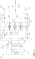
- Fig. 1 is a configuration diagram of a hot water supply system 100 (water system) in the present embodiment.
- the hot water supply system 100 mainly includes a heat pump unit 110 (heat source device), a hot water storage unit 120, a hot water supply section 140, a water stop valve 160, and a control unit 190.
- the heat pump unit 110 heats water supplied from the hot water storage unit 120 and supplies the heated water to the hot water storage unit 120.
- the hot water storage unit 120 stores the heated water supplied from the heat pump unit 110 and supplies, for example, the stored high-temperature water, to the hot water supply section 140.
- the hot water supply section 140 is a facility such as a faucet or a shower for supplying water.
- the water stop valve 160 is connected to an external water supply source such as a water supply. The water stop valve 160 is operated to supply water to the hot water storage unit 120.
- the heat pump unit 110 mainly includes a compressor 11, a water heat exchanger 12, an expansion valve 13, and an air heat exchanger 14.
- the compressor 11, the water heat exchanger 12, the expansion valve 13, and the air heat exchanger 14 are annularly connected by a refrigerant pipe and form a heat pump cycle.
- the heat pump unit 110 includes a first control apparatus 10.
- the compressor 11 includes a compression mechanism that compresses a refrigerant by driving a motor.
- the refrigerant compressed by the compressor 11 is sent to the water heat exchanger 12.
- the capacity of the heat pump unit 110 is adjustable by controlling an operating frequency of the motor.
- the water heat exchanger 12 performs heat exchange between the high-temperature refrigerant compressed by the compressor 11 and water supplied from the hot water storage unit 120 to heat the water.
- the water heat exchanger 12 is, for example, a double pipe heat exchanger formed of an outer pipe and an inner pipe inserted into the outer pipe.
- the expansion valve 13 decompresses the refrigerant heat-exchanged by passing through the water heat exchanger 12.
- the expansion valve 13 is, for example, an electric expansion valve.
- the air heat exchanger 14 performs heat exchange between the refrigerant decompressed by passing through the expansion valve 13 and outdoor air to heat the refrigerant. Outdoor air is supplied to the air heat exchanger 14 by, for example, an outdoor air fan. The refrigerant heat-exchanged by passing through the air heat exchanger 14 is sent to the compressor 11.
- the hot water storage unit 120 mainly includes a tank 21, a first water boiling pipe B1 (first pipe), a second water boiling pipe B2 (second pipe), a fourth water boiling pipe B4 (fourth pipe), a fifth water boiling pipe B5 (fifth pipe), an eighth water boiling pipe B8 (eighth pipe), a first hot water supply pipe S1 to a sixth hot water supply pipe S6, a water supply pipe L1, a water discharge pipe L2, a first water boiling valve 22 (second valve), a water boiling pump 24, a first hot water supply valve 25, a second hot water supply valve 26, and a water discharge valve 28. Furthermore, the hot water storage unit 120 includes a second control apparatus 20.
- the tank 21 stores water. Since the density of water changes according to the temperature, the water stored in the tank 21 forms layers including a high-temperature layer, a middle-temperature layer, and a low-temperature layer, sequentially from an upper side to a lower side.
- the first water boiling pipe B1 extends from a side surface of the tank 21. A distal end of the first water boiling pipe B1 on a side opposite to the tank 21 is connected to the second water boiling pipe B2.
- the second water boiling pipe B2 is connected to the first water boiling pipe B1 and extends upward.
- the second water boiling pipe B2 extends upward from the distal end of the first water boiling pipe B1.
- the second water boiling pipe B2 may extend upward from an intermediate portion of the first water boiling pipe B1.
- the second water boiling pipe B2 is connected to the first water boiling valve 22.
- the fourth water boiling pipe B4 extends from an upper surface of the tank 21. A distal end of the fourth water boiling pipe B4 on a side opposite to the tank 21 is connected to the first water boiling valve 22.
- One end of the fifth water boiling pipe B5 is connected to the first water boiling valve 22, and the other end of the fifth water boiling pipe B5 is connected to an outlet side of the water heat exchanger 12 of the heat pump unit 110.
- the eighth water boiling pipe B8 extends from a lower surface of the tank 21. A distal end of the eighth water boiling pipe B8 on a side opposite to the tank 21 is connected to an inlet side of the water heat exchanger 12 of the heat pump unit 110. The eighth water boiling pipe B8 is provided with the water boiling pump 24.
- the first water boiling valve 22 adjusts a flow path of water.
- the fourth water boiling pipe B4, the fifth water boiling pipe B5, and the second water boiling pipe B2 are connected to each other via the first water boiling valve 22.
- the first water boiling valve 22 is, for example, a three-way valve or a mixing valve. Opening and closing of the three-way valve is adjustable for each connected pipe. An opening degree of the mixing valve is adjustable for each connected pipe.
- the first water boiling valve 22 is a mixing valve.
- the tank 21, the first water boiling pipe B1, the second water boiling pipe B2, the fourth water boiling pipe B4, the fifth water boiling pipe B5, the eighth water boiling pipe B8, the first water boiling valve 22, and the water heat exchanger 12 of the heat pump unit 110 form a water boiling circuit C1 for heating the water in the tank 21.
- the first hot water supply pipe S1 extends from a side surface of the tank 21. A distal end of the first hot water supply pipe S1 on a side opposite to the tank 21 is connected to the second hot water supply pipe S2.
- the second hot water supply pipe S2 is connected to the first hot water supply pipe S1 and extends upward.
- the second hot water supply pipe S2 extends upward from the distal end of the first hot water supply pipe S1.
- the second hot water supply pipe S2 may extend upward from an intermediate portion of the first hot water supply pipe S1.
- the second hot water supply pipe S2 is connected to the first hot water supply valve 25.
- the third hot water supply pipe S3 extends downward from the distal end of the first hot water supply pipe S1.
- the third hot water supply pipe S3 is connected to the second hot water supply valve 26.
- the fourth hot water supply pipe S4 extends from the upper surface of the tank 21. A distal end of the fourth hot water supply pipe S4 on a side opposite to the tank 21 is connected to the first hot water supply valve 25.
- One end of the fifth hot water supply pipe S5 is connected to the first hot water supply valve 25, and the other end of the fifth hot water supply pipe S5 is connected to the hot water supply section 140.
- the sixth hot water supply pipe S6 extends from the lower surface of the tank 21. A distal end of the sixth hot water supply pipe S6 on a side opposite to the tank 21 is connected to the second hot water supply valve 26.
- the second hot water supply valve 26 is an electric on-off valve.
- One end of the water supply pipe L1 is connected to the second hot water supply valve 26, and the other end of the water supply pipe L1 is connected to the water stop valve 160 outside the hot water storage unit 120.
- the water discharge pipe L2 extends from the lower surface of the tank 21.
- the water discharge pipe L2 is provided with the water discharge valve 28.
- the water discharge pipe L2 is connected to a pipe for discharging water outside the hot water storage unit 120.
- the first hot water supply valve 25 adjusts a flow path of water.
- the fourth hot water supply pipe S4, the fifth hot water supply pipe S5, and the second hot water supply pipe S2 are connected to each other via the first hot water supply valve 25.
- the first hot water supply valve 25 is a three-way valve.
- the second hot water supply valve 26 adjusts a flow path of water.
- the third hot water supply pipe S3, the sixth hot water supply pipe S6, and the water supply pipe L1 are connected to each other via the second hot water supply valve 26.
- the second hot water supply valve 26 is a three-way valve.
- the tank 21, the first hot water supply pipe S1 to the second hot water supply pipe S2, the fourth hot water supply pipe S4 to the sixth hot water supply pipe S6, the water supply pipe L1, and the hot water supply section 140 form a hot water supply circuit C2 for supplying water in the tank 21.
- the water discharge valve 28 is operated to discharge the water in the tank 21, in the water boiling circuit C1, and in the hot water supply circuit C2 to the outside.
- the control unit 190 mainly includes the first control apparatus 10 of the heat pump unit 110 and the second control apparatus 20 of the hot water storage unit 120.
- the first control apparatus 10 and the second control apparatus 20 typically include a microcomputer including a control arithmetic device and a storage device, and input and output circuits.
- the control arithmetic device is a processor such as a CPU or a GPU.
- the control arithmetic device reads a control program stored in the storage device and controls operations of the hot water supply system 100 in accordance with the control program.
- the control arithmetic device can write a calculation result in the storage device and read information stored in the storage device in accordance with the control program.
- the control unit 190 controls the compressor 11, the expansion valve 13, the first water boiling valve 22, the water boiling pump 24, the first hot water supply valve 25, the second hot water supply valve 26, the water discharge valve 28, and the like, on the basis of a signal from a temperature sensor (not illustrated) or the like provided in the tank 21.
- the hot water supply system 100 mainly performs a water boiling operation and a hot water supply operation.
- the control unit 190 controls these operations performed by the hot water supply system 100.
- the water boiling operation is an operation of heating the water in the tank 21 by the heat pump unit 110.
- the control unit 190 drives the water boiling pump 24 to circulate the water in the tank 21 through the first water boiling pipe B1, the second water boiling pipe B2, the fourth water boiling pipe B4, the fifth water boiling pipe B5, and the eighth water boiling pipe B8 while heating the water in the water heat exchanger 12.
- the control unit 190 controls the operation frequency of the motor of the compressor 11 and the opening degree of the expansion valve 13 to adjust the temperature or the like of the water heated in the water heat exchanger 12.
- the control unit 190 performs a first water boiling operation.
- the water in the tank 21 is heated by sequentially being made to pass through the eighth water boiling pipe B8, the water heat exchanger 12, the fifth water boiling pipe B5, and the fourth water boiling pipe B4.
- the control unit 190 controls the first water boiling valve 22 so as to open a fourth water boiling pipe B4 side and a fifth water boiling pipe B5 side of the first water boiling valve 22 and close a second water boiling pipe B2 side of the first water boiling valve 22.
- the control unit 190 drives the water boiling pump 24 after controlling the first water boiling valve 22 as described above, the water from the low-temperature layer in the tank 21 is heated by the water heat exchanger 12 and is returned to the high-temperature layer in the tank 21.
- the control unit 190 performs a second water boiling operation.
- the water in the tank 21 is heated by sequentially being made to pass through the eighth water boiling pipe B8, the water heat exchanger 12, the fifth water boiling pipe B5, the second water boiling pipe B2, and the first water boiling pipe B1.
- the control unit 190 controls the first water boiling valve 22 so as to open the second water boiling pipe B2 side and the fifth water boiling pipe B5 side of the first water boiling valve 22 and close the fourth water boiling pipe B4 side of the first water boiling valve 22.
- the control unit 190 drives the water boiling pump 24 after controlling the first water boiling valve 22 as described above, the water from the low-temperature layer in the tank 21 is heated by the water heat exchanger 12 and is returned to the middle-temperature layer in the tank 21.
- the heating of the water by the heat pump unit 110 is insufficient for a while after the start of the water boiling operation. Therefore, there is concern that, if the first water boiling operation is performed from the start of the water boiling operation, the temperature in the tank 21 may decrease as the water from the low-temperature layer in the tank 21 is returned to the high-temperature layer in the tank 21. Therefore, the control unit 190 may perform the second water boiling operation at the start of the water boiling operation, thereafter, may gradually reduce the opening degree of the second water boiling pipe B2 side of the first water boiling valve 22 and gradually increase the opening degree of the fourth water boiling pipe B4 side of the first water boiling valve 22, and may finally perform the first water boiling operation.
- control unit 190 controls the first water boiling valve 22 as described above, the water from the low-temperature layer in the tank 21 is returned to the middle-temperature layer in the tank 21 for a while after the start of the water boiling operation. As a result, the temperature in the tank 21 is less likely to decrease.
- the hot water supply operation is an operation of releasing water at a predetermined temperature from the hot water supply section 140 using the water in the tank 21.
- the predetermined temperature is, for example, set by a user, of the hot water supply system 100, using a remote controller (not illustrated).
- control unit 190 controls the first hot water supply valve 25 so as to open a fourth hot water supply pipe S4 side and a fifth hot water supply pipe S5 side of the first hot water supply valve 25 and close a second hot water supply pipe S2 side of the first hot water supply valve 25 in order to release water at a predetermined temperature from the hot water supply section 140. Furthermore, the control unit 190 controls the second hot water supply valve 26 so as to open a water supply pipe L1 side and a sixth hot water supply pipe S6 side of the second hot water supply valve 26 and close a third hot water supply pipe S3 side of the second hot water supply valve 26.
- control unit 190 controls the first hot water supply valve 25 so as to open in three ways including the fourth hot water supply pipe S4 side, the fifth hot water supply pipe S5 side, and the second hot water supply pipe S2 side in order to release water at a predetermined temperature from the hot water supply section 140. Furthermore, the control unit 190 controls the second hot water supply valve 26 so as to open the water supply pipe L1 side and the sixth hot water supply pipe S6 side of the second hot water supply valve 26 and close the third hot water supply pipe S3 side of the second hot water supply valve 26.
- Fig. 2 is a view illustrating an example of a pipe B1' of related art extending from a tank 21'.
- the pipe B1' extends horizontally (in a left-right direction) from a side surface of the tank 21'.
- a distal end of the pipe B1' on a side opposite to the tank 21' is connected to a pipe B2'.
- the pipe B2' extends upward from the distal end of the pipe B1'.
- Fig. 3 is an enlarged view of a vicinity of the first water boiling pipe B1 in the present embodiment.
- the first water boiling pipe B1 includes a suppressing portion 40.
- the suppressing portion 40 suppresses water in the second water boiling pipe B2 from flowing into the tank 21 through the first water boiling pipe B1 during a first state.
- the first state is a state in which water is not made to flow between the tank 21 and the first water boiling pipe B1.
- the first state is, for example, a state in which the control unit 190 closes the water discharge valve 28, stops the compressor 11 and the water boiling pump 24, and opens, in three ways, the first water boiling valve 22, the first hot water supply valve 25, and the second hot water supply valve 26 and a user does not release water from the hot water supply section 140.
- the suppressing portion 40 is a gradient portion 40a.
- the gradient portion 40a rises toward the tank 21. As illustrated in Fig. 3 , a position P1 of a lowermost portion of a flow path at an end portion of the gradient portion 40a on a tank 21 side is higher than a position P2 of an uppermost portion of the flow path at an end portion of the gradient portion 40a on a side opposite to the tank 21.
- the hot water supply system 100 can suppress the low-temperature water in the second water boiling pipe B2 from flowing into the tank 21 through the first water boiling pipe B1, and can prevent the temperature stratification of the water in the tank 21 from being disrupted.
- the hot water supply system 100 (water system) of the present embodiment includes the tank 21, the first water boiling pipe B1 (first pipe), the second water boiling pipe B2 (second pipe), the heat pump unit 110 (heat source device), and the control unit 190.
- the tank 21 stores water.
- the first water boiling pipe B1 extends from the tank 21.
- the second water boiling pipe B2 is connected to the first water boiling pipe B1.
- the heat pump unit 110 heats water.
- the first water boiling pipe B1 includes the suppressing portion 40.
- the suppressing portion 40 suppresses the water in the second water boiling pipe B2 from flowing into the tank 21 through the first water boiling pipe B1 during the first state.
- the first state is a state in which water is not made to flow between the tank 21 and the first water boiling pipe B1.
- the first water boiling pipe B1, the second water boiling pipe B2, and the heat pump unit 110 form the water boiling circuit C1 for heating the water in the tank 21.
- the suppressing portion 40 suppresses the water in the second water boiling pipe B2 from flowing into the tank 21 through the first water boiling pipe B1 during the first state.
- the first state is a state in which water is not made to flow between the tank 21 and the first water boiling pipe B1.
- the hot water supply system 100 can suppress the low-temperature water in the second water boiling pipe B2 from flowing into the tank 21 through the first water boiling pipe B1, and can prevent the temperature stratification of the water in the tank 21 from being disrupted.
- the suppressing portion 40 is the gradient portion 40a.
- the gradient portion 40a rises toward the tank 21.
- the hot water supply system 100 can suppress the low-temperature water in the second water boiling pipe B2 from flowing into the tank 21 through the first water boiling pipe B1.
- the position P1 of the lowermost portion of the flow path at the end portion of the gradient portion 40a on the tank 21 side is higher than the position P2 of the uppermost portion of the flow path at the end portion of the gradient portion 40a on a side opposite to the tank 21.
- the hot water supply system 100 can more effectively suppress the low-temperature water in the second water boiling pipe B2 from flowing into the tank 21 through the first water boiling pipe B1 during the first state.
- the hot water supply system 100 of the present embodiment further includes the first water boiling valve 22 (second valve), the fourth water boiling pipe B4 (fourth pipe), the fifth water boiling pipe B5 (fifth pipe), and the eighth water boiling pipe B8 (eighth pipe).
- the first water boiling valve 22 adjusts the flow path of the water.
- the fourth water boiling pipe B4 extends from the upper surface of the tank 21.
- the fifth water boiling pipe B5 is connected to the heat pump unit 110.
- the eighth water boiling pipe B8 extends from the lower surface of the tank 21.
- the eighth water boiling pipe B8 is connected to the heat pump unit 110.
- the first water boiling pipe B1 extends from the side surface of the tank 21.
- the fourth water boiling pipe B4, the fifth water boiling pipe B5, and the second water boiling pipe B2 are connected to each other via the first water boiling valve 22.
- the control unit 190 controls the second water boiling pipe B2 so as to open the second water boiling pipe B2 side of the first water boiling valve 22 during the first state.
- the control unit 190 performs the first water boiling operation.
- the water in the tank 21 is heated by sequentially being made to pass through the eighth water boiling pipe B8, the heat pump unit 110, the fifth water boiling pipe B5, and the fourth water boiling pipe B4.
- the control unit 190 performs the second water boiling operation.
- the water in the tank 21 is heated by sequentially being made to pass through the eighth water boiling pipe B8, the heat pump unit 110, the fifth water boiling pipe B5, the second water boiling pipe B2, and the first water boiling pipe B1.
- Fig. 4 is an enlarged view of a vicinity of the first water boiling pipe B1 in the present modification.
- the suppressing portion 40 is the gradient portion 40a.
- the suppressing portion 40 may be a gradient portion 40b, for example.
- a position P3 of a lowermost portion of a flow path at a first end portion of the gradient portion 40b on the tank 21 side may be higher than a position P4 of a lowermost portion of the flow path at a second end portion of the gradient portion 40b on a side opposite to the tank 21.
- an area of a first portion A2 (hatched portion on the left side) higher than the position P3 of the lowermost portion of the flow path at the first end portion may be 9% or more of an area of the flow path section A1, for example.
- the hot water supply system 100 can suppress the low-temperature water in the second water boiling pipe B2 from flowing into the tank 21 through the first water boiling pipe B1 during the first state.
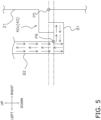
- Fig. 5 is an enlarged view of a vicinity of the first water boiling pipe B1 in the present modification.
- the suppressing portion 40 is the gradient portion 40a.
- the suppressing portion 40 may be a stepped portion 40c, for example. The stepped portion 40c rises toward the tank 21.
- the hot water supply system 100 can suppress the low-temperature water in the second water boiling pipe B2 from flowing into the tank 21 through the first water boiling pipe B1.
- a position P5 of a lowermost portion of a flow path at an end portion of the stepped portion 40c on the tank 21 side may be higher than a position P6 of an uppermost portion of the flow path at an end portion of the stepped portion 40c on a side opposite to the tank 21.
- the hot water supply system 100 can more effectively suppress the low-temperature water in the second water boiling pipe B2 from flowing into the tank 21 through the first water boiling pipe B1 during the first state.
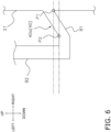
- Fig. 6 is an enlarged view of a vicinity of the first water boiling pipe B1 in the present modification.
- the gradient portion 40a is the entirety of the first water boiling pipe B1.
- the gradient portion 40a may be a part of the first water boiling pipe B1, for example.
- the position P1 of the lowermost portion of the flow path at the end portion of the gradient portion 40a on the tank 21 side is higher than the position P2 of the uppermost portion of the flow path at the end portion of the gradient portion 40a on a side opposite to the tank 21.
- the suppressing portion 40 is the gradient portion 40a.
- the suppressing portion 40 may be a first valve provided in the first water boiling pipe B1, for example.
- the first valve is, for example, an on-off valve or a check valve.
- the control unit 190 closes the first valve during the first state and opens the first valve during a second state.
- the second state is a state in which water is made to flow between the tank 21 and the first water boiling pipe B1.
- the first valve is a check valve, the first valve is provided so that the water in the tank 21 does not flow out through the first water boiling pipe B1.
- the hot water supply system 100 can suppress the low-temperature water in the second water boiling pipe B2 from flowing into the tank 21 through the first water boiling pipe B1.
- the first water boiling pipe B1 (first pipe) extending from the side surface of the tank 21 includes the suppressing portion 40.
- the fourth water boiling pipe B4 extending from the upper surface of the tank 21 may include the suppressing portion 40, as the fourth water boiling pipe B4 (first pipe) and the second water boiling pipe B2 (second pipe) (or the fifth water boiling pipe B5 (second pipe)) .
- Fig. 7 is an enlarged view of a vicinity of the fourth water boiling pipe B4 in the present modification.
- the suppressing portion 40 is a gradient portion 40d.
- the suppressing portion 40 may be a first valve provided in the fourth water boiling pipe B4.
- the first water boiling valve 22 opens in three ways. A position P7 of a lowermost portion of a flow path at an end portion of the gradient portion 40d on the tank 21 side is higher than a position P8 of an uppermost portion of the flow path at an end portion of the gradient portion 40d on a side opposite to the tank 21.
- the hot water supply system 100 can suppress the low-temperature water in the second water boiling pipe B2 or in the fifth water boiling pipe B5 from flowing into the tank 21 through the fourth water boiling pipe B4 (as illustrated in Fig. 7 , relatively high-temperature water flows (dotted line arrows) into the tank 21, but when compared to the temperature of the water in the tank 21, it is still the case where the low-temperature water flows into the tank 21), and can prevent the temperature stratification of the water in the tank 21 from being disrupted.
- the hot water supply system 100 a sufficient amount of water does not remain in the fourth water boiling pipe B4 when the water in the tank 21, in the water boiling circuit C1, and in the hot water supply circuit C2 is discharged to the outside. Thus, it is possible to prevent the fourth water boiling pipe B4 from freezing and being damaged.
- the present embodiment is basically the same as the first embodiment except for the contents described in the present embodiment.
- Fig. 8 is a configuration diagram of a hot water supply system 200 (water system) in the present embodiment.
- a hot water storage unit 220 includes a third water boiling pipe B3 (third pipe).
- the eighth water boiling pipe B8 includes a sixth water boiling pipe B6 (sixth pipe) and a seventh water boiling pipe B7 (seventh pipe).
- the third water boiling pipe B3 is connected to the first water boiling pipe B1 and extends downward.
- the third water boiling pipe B3 extends downward from the distal end of the first water boiling pipe B1.
- the first water boiling pipe B1, the second water boiling pipe B2, and the third water boiling pipe B3 are connected to each other.
- the third water boiling pipe B3 is connected to the sixth water boiling pipe B6 and the seventh water boiling pipe B7.
- the third water boiling pipe B3, the sixth water boiling pipe B6, and the seventh water boiling pipe B7 are connected to each other.
- the sixth water boiling pipe B6 extends from the lower surface of the tank 21. A distal end of the sixth water boiling pipe B6 on a side opposite to the tank 21 is connected to the third water boiling pipe B3 and the seventh water boiling pipe B7.
- One end of the seventh water boiling pipe B7 is connected to the third water boiling pipe B3 and the sixth water boiling pipe B6, and the other end of the seventh water boiling pipe B7 is connected to the inlet side of the water heat exchanger 12 of the heat pump unit 110.
- the seventh water boiling pipe B7 is provided with the water boiling pump 24.
- the tank 21, the first water boiling pipe B1 to the seventh water boiling pipe B7, the first water boiling valve 22, and the water heat exchanger 12 of the heat pump unit 110 form a water boiling circuit C3 for heating the water in the tank 21.
- the control unit 190 drives the water boiling pump 24 to circulate the water in the tank 21 through the first water boiling pipe B1 to the seventh water boiling pipe B7 while heating the water in the water heat exchanger 12.
- control unit 190 controls the first water boiling valve 22 so as to open the fourth water boiling pipe B4 side and the fifth water boiling pipe B5 side of the first water boiling valve 22 and close the second water boiling pipe B2 side of the first water boiling valve 22.
- control unit 190 drives the water boiling pump 24 after controlling the first water boiling valve 22 as described above, the water from the low-temperature layer and the middle-temperature layer in the tank 21 is heated by the water heat exchanger 12 and is returned to the high-temperature layer in the tank 21.
- Fig. 9 is a view illustrating an example of a pipe B1' of related art extending from the tank 21'.
- the pipe B1' extends horizontally (in the left-right direction) from the side surface of the tank 21'.
- the distal end of the pipe B1' on a side opposite to the tank 21' is branched into the pipe B2' and a pipe B3' .
- the pipe B2' extends upward from the distal end of the pipe B1', and the pipe B3' extends downward from the distal end of the pipe B1'.
- the temperature of the water in the vicinity of the center inside the pipe B2' and inside the pipe B3' becomes relatively high, and the water flows upward (dotted line arrows) in the pipes.
- convection occurs in the water in the pipe B2' and in the pipe B3'.
- the temperature stratification of the water in the tank 21' may be disrupted.
- Fig. 10 is an enlarged view of a vicinity of the first water boiling pipe B1 in the present embodiment.
- the first water boiling pipe B1 includes the gradient portion 40a rising toward the tank 21.
- the gradient portion 40a suppresses the water in the second water boiling pipe B2 from flowing into the tank 21 through the first water boiling pipe B1 during the first state.
- the position P1 of the lowermost portion of the flow path at the end portion of the gradient portion 40a on the tank 21 side is higher than the position P2 of the uppermost portion of the flow path at the end portion of the gradient portion 40a on a side opposite to the tank 21.
- the hot water supply system 200 can suppress the low-temperature water in the second water boiling pipe B2 from flowing into the tank 21 through the first water boiling pipe B1, and can prevent the temperature stratification of the water in the tank 21 from being disrupted.
- the first water boiling pipe B1 includes the gradient portion 40a. Therefore, in the hot water supply system 200, a sufficient amount of water does not remain in the first water boiling pipe B1 when the water in the tank 21, in the water boiling circuit C3, and in the hot water supply circuit C2 is discharged to the outside by, for example, opening the water discharge valve 28 in a state in which the water stop valve 160 is closed. Thus, it is possible to prevent the first water boiling pipe B1 from freezing and being damaged.
- the hot water supply system 200 of the present embodiment further includes the third water boiling pipe B3 (third pipe) .
- the third water boiling pipe B3 is connected to the first water boiling pipe B1.
- the eighth water boiling pipe B8 includes the sixth water boiling pipe B6 (sixth pipe) and the seventh water boiling pipe B7 (seventh pipe).
- the sixth water boiling pipe B6 extends from the lower surface of the tank 21.
- the seventh water boiling pipe B7 is connected to the heat pump unit 110.
- the third water boiling pipe B3, the sixth water boiling pipe B6, and the seventh water boiling pipe B7 are connected to each other.
- the gradient portion 40a suppresses the water in the second water boiling pipe B2 from flowing into the tank 21 through the first water boiling pipe B1 during the first state.
- the hot water supply system 200 can suppress the low-temperature water in the second water boiling pipe B2 from flowing into the tank 21 through the first water boiling pipe B1, and can prevent the temperature stratification of the water in the tank 21 from being disrupted.
- a sufficient amount of water does not remain in the first water boiling pipe B1 when the water in the tank 21, in the water boiling circuit C3, and in the hot water supply circuit C2 is discharged to the outside. Thus, it is possible to prevent the first water boiling pipe B1 from freezing and being damaged.
- the suppressing portion 40 is the gradient portion 40a.
- the suppressing portion 40 may be the gradient portion 40b or the stepped portion 40c, or as illustrated in Fig. 6 , the gradient portion 40a may be a part of the first water boiling pipe B1, for example.
- the fourth water boiling pipe B4 extending from the upper surface of the tank 21 may include the gradient portion 40d, as the fourth water boiling pipe B4 (first pipe), the second water boiling pipe B2 (second pipe), and the fifth water boiling pipe B5 (third pipe).
- the present embodiment is basically the same as the first embodiment except for the contents described in the present embodiment.
- FIG. 11 is a configuration diagram of a hot water supply system 300 (water system) in the present embodiment.
- a hot water storage unit 320 includes the third water boiling pipe B3 (third pipe), the sixth water boiling pipe B6 (sixth pipe), and the seventh water boiling pipe B7 (seventh pipe).
- the third water boiling pipe B3 is connected to the first water boiling pipe B1 and extends downward. In the present modification, the third water boiling pipe B3 extends downward from the distal end of the first water boiling pipe B1. Furthermore, the third water boiling pipe B3 is connected to the sixth water boiling pipe B6 and the seventh water boiling pipe B7. The third water boiling pipe B3, the sixth water boiling pipe B6, and the seventh water boiling pipe B7 are connected to each other.
- the sixth water boiling pipe B6 extends from the lower surface of the tank 21.
- the distal end of the sixth water boiling pipe B6 on a side opposite to the tank 21 is connected to the third water boiling pipe B3 and the seventh water boiling pipe B7.
- One end of the seventh water boiling pipe B7 is connected to the third water boiling pipe B3 and the sixth water boiling pipe B6, and the other end of the seventh water boiling pipe B7 is connected to the inlet side of the water heat exchanger 12 of the heat pump unit 110.
- the seventh water boiling pipe B7 is provided with the water boiling pump 24.
- the suppressing portion 40 is a third water boiling valve 40e (third valve).
- the third water boiling valve 40e is connected to an end portion of the first water boiling pipe B1 on a side opposite to the tank 21.
- the third water boiling valve 40e adjusts a flow path of water.
- the first water boiling pipe B1, the second water boiling pipe B2, and the third water boiling pipe B3 are connected to each other via the third water boiling valve 40e.
- the third water boiling valve 40e is a mixing valve.
- the first water boiling pipe B1 extends horizontally (in the left-right direction) from the side surface of the tank 21.
- the tank 21, the first water boiling pipe B1 to the seventh water boiling pipe B7, the first water boiling valve 22, the third water boiling valve 40e, and the water heat exchanger 12 of the heat pump unit 110 form a water boiling circuit C4 for heating the water in the tank 21.
- the control unit 190 controls the compressor 11, the expansion valve 13, the first water boiling valve 22, the third water boiling valve 40e, the water boiling pump 24, the first hot water supply valve 25, the second hot water supply valve 26, the water discharge valve 28, and the like, on the basis of a signal from a temperature sensor (not illustrated) or the like provided in the tank 21.
- the control unit 190 drives the water boiling pump 24 to circulate the water in the tank 21 through the first water boiling pipe B1 to the seventh water boiling pipe B7 while heating the water in the water heat exchanger 12.
- the control unit 190 performs a third water boiling operation.
- the water in the tank 21 is heated by sequentially being made to pass through the first water boiling pipe B1, the third water boiling pipe B3, the seventh water boiling pipe B7, the water heat exchanger 12, the fifth water boiling pipe B5, and the fourth water boiling pipe B4.
- the control unit 190 controls the first water boiling valve 22 so as to open the fourth water boiling pipe B4 side and the fifth water boiling pipe B5 side of the first water boiling valve 22 and close the second water boiling pipe B2 side of the first water boiling valve 22.
- control unit 190 controls the third water boiling valve 40e so as to open a first water boiling pipe B1 side and a third water boiling pipe B3 side of the third water boiling valve 40e and close a second water boiling pipe B2 side of the third water boiling valve 40e.
- control unit 190 drives the water boiling pump 24 after controlling the first water boiling valve 22 and the third water boiling valve 40e as described above, the water from the low-temperature layer and the middle-temperature layer in the tank 21 is heated by the water heat exchanger 12 and is returned to the high-temperature layer in the tank 21.
- the heating of the water by the heat pump unit 110 is insufficient for a while after the start of the water boiling operation. Therefore, there is concern that, if the water from the low-temperature layer in the tank 21 is returned to the high-temperature layer in the tank 21 from the start of the water boiling operation, the temperature in the tank 21 may decrease.
- control unit 190 may perform the third water boiling operation at the start of the water boiling operation, thereafter, may control the third water boiling valve 40e so as to gradually reduce the opening degree of the third water boiling pipe B3 side of the third water boiling valve 40e and gradually increase the opening degree of the second water boiling pipe B2 side of the third water boiling valve 40e, and may finally control the third water boiling valve 40e so as to open the first water boiling pipe B1 side and the second water boiling pipe B2 side of the third water boiling valve 40e and close the third water boiling pipe B3 side of the third water boiling valve 40e.
- control unit 190 controls the third water boiling valve 40e as described above, the water from the low-temperature layer and the middle-temperature layer in the tank 21 is returned to the high-temperature layer in the tank 21 for a while after the start of the water boiling operation. As a result, the temperature in the tank 21 is less likely to decrease.
- Fig. 12 is an enlarged view of a vicinity of the first water boiling pipe B1 in the present embodiment.
- the suppressing portion 40 suppresses the water in the second water boiling pipe B2 from flowing into the tank 21 through the first water boiling pipe B1 during the first state.
- the suppressing portion 40 is the third water boiling valve 40e.
- the third water boiling valve 40e is connected to the end portion of the first water boiling pipe B1 on a side opposite to the tank 21.
- the first water boiling pipe B1, the second water boiling pipe B2, and the third water boiling pipe B3 are connected to each other via the third water boiling valve 40e.
- the control unit 190 controls the third water boiling valve 40e so as to open the second water boiling pipe B2 side and the third water boiling pipe B3 side of the third water boiling valve 40e and close the first water boiling pipe B1 side of the third water boiling valve 40e during the first state.
- the hot water supply system 200 can suppress the low-temperature water in the second water boiling pipe B2 from flowing into the tank 21 through the first water boiling pipe B1, and can prevent the temperature stratification of the water in the tank 21 from being disrupted.
- the hot water supply system 200 of the present embodiment further includes the first water boiling valve 22, the third water boiling pipe B3 (third pipe), the fourth water boiling pipe B4, the fifth water boiling pipe B5, the sixth water boiling pipe B6 (sixth pipe), and the seventh water boiling pipe B7 (seventh pipe).
- the first water boiling valve 22 adjusts the flow path of the water.
- the third water boiling pipe B3 is connected to the first water boiling pipe B1.
- the fourth water boiling pipe B4 extends from the upper surface of the tank 21.
- the fifth water boiling pipe B5 is connected to the heat pump unit 110.
- the sixth water boiling pipe B6 extends from the lower surface of the tank 21.
- the seventh water boiling pipe B7 is connected to the heat pump unit 110.
- the first water boiling pipe B1 extends from the side surface of the tank 21.
- the fourth water boiling pipe B4, the fifth water boiling pipe B5, and the second water boiling pipe B2 are connected to each other via the first water boiling valve 22.
- the third water boiling pipe B3, the sixth water boiling pipe B6, and the seventh water boiling pipe B7 are connected to each other.
- the suppressing portion 40 is the third water boiling valve 40e (third valve).
- the third water boiling valve 40e is connected to the end portion of the first water boiling pipe B1 on a side opposite to the tank 21.
- the first water boiling pipe B1 adjusts the flow path of water.
- the control unit 190 controls the third water boiling valve 40e so as to open the second water boiling pipe B2 side and the third water boiling pipe B3 side of the third water boiling valve 40e and close the first water boiling pipe B1 side of the third water boiling valve 40e during the first state.
- the first water boiling pipe B1, the second water boiling pipe B2, and the third water boiling pipe B3 are connected to each other via the third water boiling valve 40e.
- the control unit 190 controls the third water boiling valve 40e so as to open the second water boiling pipe B2 side and the third water boiling pipe B3 side of the third water boiling valve 40e and close the first water boiling pipe B1 side of the third water boiling valve 40e during the first state.
- the hot water supply system 200 can suppress the low-temperature water in the second water boiling pipe B2 from flowing into the tank 21 through the first water boiling pipe B1, and can prevent the temperature stratification of the water in the tank 21 from being disrupted.
- the third water boiling valve 40e is a mixing valve.
- An opening degree of the mixing valve is adjustable for each connected pipe.
- the hot water supply system 200 can return the water from the low-temperature layer and the middle-temperature layer in the tank 21 to the high-temperature layer in the tank 21 for a while after the start of the water boiling operation, and thereafter, can gradually reduce the amount of water to be returned from the middle-temperature layer to the high-temperature layer. In this manner, the hot water supply system 200 can flexibly perform the water boiling operation.
- the control unit 190 performs the third water boiling operation.
- the water in the tank 21 is heated by sequentially being made to pass through the first water boiling pipe B1, the third water boiling pipe B3, the seventh water boiling pipe B7, the heat pump unit 110, the fifth water boiling pipe B5, and the fourth water boiling pipe B4.
- the present embodiment is basically the same as the second embodiment except for the contents described in the present embodiment.
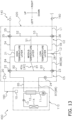
- Fig. 13 is a configuration diagram of a hot water supply system 400 (water system) in the present embodiment.
- a hot water storage unit 420 includes a second water boiling valve 23 (fourth valve).
- the second water boiling valve 23 adjusts a flow path of water.
- the third water boiling pipe B3, the sixth water boiling pipe B6, and the seventh water boiling pipe B7 are connected to each other via the second water boiling valve 23.
- the second water boiling valve 23 is a mixing valve.
- the tank 21, the first water boiling pipe B1 to the seventh water boiling pipe B7, the first water boiling valve 22, the second water boiling valve 23, and the water heat exchanger 12 of the heat pump unit 110 form a water boiling circuit C5 for heating the water in the tank 21.
- the control unit 190 controls the compressor 11, the expansion valve 13, the first water boiling valve 22, the second water boiling valve 23, the water boiling pump 24, the first hot water supply valve 25, the second hot water supply valve 26, the water discharge valve 28, and the like, on the basis of a signal from a temperature sensor (not illustrated) or the like provided in the tank 21.
- the control unit 190 performs the third water boiling operation.
- the water in the tank 21 is heated by sequentially being made to pass through the first water boiling pipe B1, the third water boiling pipe B3, the seventh water boiling pipe B7, the water heat exchanger 12, the fifth water boiling pipe B5, and the fourth water boiling pipe B4.
- the control unit 190 controls the first water boiling valve 22 so as to open the fourth water boiling pipe B4 side and the fifth water boiling pipe B5 side of the first water boiling valve 22 and close the second water boiling pipe B2 side of the first water boiling valve 22.
- control unit 190 controls the second water boiling valve 23 so as to open the third water boiling pipe B3 side and a seventh water boiling pipe B7 side of the second water boiling valve 23 and close a sixth water boiling pipe B6 side of the second water boiling valve 23.
- the control unit 190 drives the water boiling pump 24 after controlling the first water boiling valve 22 and the second water boiling valve 23 as described above, the water from the middle-temperature layer in the tank 21 is heated by the water heat exchanger 12 and is returned to the high-temperature layer in the tank 21.
- the first water boiling pipe B1 includes the gradient portion 40a rising toward the tank 21.
- the gradient portion 40a suppresses the water in the second water boiling pipe B2 from flowing into the tank 21 through the first water boiling pipe B1 during the first state.
- the first state is, for example, a state in which the control unit 190 closes the water discharge valve 28, stops the compressor 11 and the water boiling pump 24, and opens, in three ways, the first water boiling valve 22, the second water boiling valve 23, the first hot water supply valve 25, and the second hot water supply valve 26, and a user does not release water from the hot water supply section 140.
- the hot water supply system 200 can suppress the low-temperature water in the second water boiling pipe B2 from flowing into the tank 21 through the first water boiling pipe B1, and can prevent the temperature stratification of the water in the tank 21 from being disrupted.
- the first water boiling pipe B1 includes the gradient portion 40a. Therefore, in the hot water supply system 200, a sufficient amount of water does not remain in the first water boiling pipe B1 when the water in the tank 21, in the water boiling circuit C5, and in the hot water supply circuit C2 is discharged to the outside by, for example, opening the water discharge valve 28 in a state in which the water stop valve 160 is closed. Thus, it is possible to prevent the first water boiling pipe B1 from freezing and being damaged.
- the hot water supply system 200 of the present embodiment further includes the second water boiling valve 23 (fourth valve).
- the second water boiling valve 23 adjusts the flow path of the water.
- the third water boiling pipe B3, the sixth water boiling pipe B6, and the seventh water boiling pipe B7 are connected to each other via the second water boiling valve 23.
- the control unit 190 performs the third water boiling operation.
- the water in the tank 21 is heated by sequentially being made to pass through the first water boiling pipe B1, the third water boiling pipe B3, the seventh water boiling pipe B7, the heat pump unit 110, the fifth water boiling pipe B5, and the fourth water boiling pipe B4.
Landscapes
- Engineering & Computer Science (AREA)
- Physics & Mathematics (AREA)
- Thermal Sciences (AREA)
- Chemical & Material Sciences (AREA)
- Combustion & Propulsion (AREA)
- Mechanical Engineering (AREA)
- General Engineering & Computer Science (AREA)
- Computer Hardware Design (AREA)
- Heat-Pump Type And Storage Water Heaters (AREA)
Abstract
Description
- The present disclosure relates to a water system.
- As described in PTL 1 (
Japanese Unexamined Patent Application Publication No. 2012-042090 - When a state in which water is not made to flow between a tank and a pipe extending from the tank continues, the pipe is cooled by the ambient temperature, which causes a temperature difference in the pipe. At this time, there is a problem where there is concern that convection may occur in the water in the pipe, causing low-temperature water to flow into the tank and disrupting the temperature stratification of the water in the tank.
- A water system according to a first aspect includes a tank, a first pipe, a second pipe, a heat source device, and a control unit. The tank stores water. The first pipe extends from the tank. The second pipe is connected to the first pipe. The heat source device heats water. The first pipe includes a suppressing portion. The suppressing portion suppresses water in the second pipe from flowing into the tank through the first pipe during a first state. The first state is a state in which water is not made to flow between the tank and the first pipe. The first pipe, the second pipe, and the heat source device form a water boiling circuit for heating the water in the tank.
- In the water system according to the first aspect, the suppressing portion suppresses water in the second pipe from flowing into the tank through the first pipe during the first state. The first state is a state in which water is not made to flow between the tank and the first pipe. As a result, during the first state in which water is not made to flow between the tank and the first pipe, the water system can suppress low-temperature water in the second pipe from flowing into the tank through the first pipe, and can prevent the temperature stratification of the water in the tank from being disrupted.
- A water system according to a second aspect is the water system according to the first aspect, in which the suppressing portion is a gradient portion or a stepped portion. The gradient portion or the stepped portion rises toward the tank.
- With such a configuration, the water system according to the second aspect can suppress the low-temperature water in the second pipe from flowing into the tank through the first pipe during the first state.
- A water system according to a third aspect is the water system according to the second aspect, in which a position of a lowermost portion of a flow path at an end portion of the gradient portion or the stepped portion on a tank side is higher than a position of an uppermost portion of the flow path at an end portion of the gradient portion or the stepped portion on a side opposite to the tank.
- With such a configuration, the water system according to the third aspect can more effectively suppress the low-temperature water in the second pipe from flowing into the tank through the first pipe during the first state.
- A water system according to a fourth aspect is the water system according to the first aspect, in which the suppressing portion is a first valve provided in the first pipe.
- With such a configuration, the water system according to the fourth aspect can suppress the low-temperature water in the second pipe from flowing into the tank through the first pipe during the first state.
- A water system according to a fifth aspect is the water system according to any one of the first to fourth aspects and further includes a second valve, a fourth pipe, a fifth pipe, and an eighth pipe. The second valve adjusts a flow path of water. The fourth pipe extends from an upper surface of the tank. The fifth pipe is connected to the heat source device. The eighth pipe extends from a lower surface of the tank. The eighth pipe is connected to the heat source device. The first pipe extends from a side surface of the tank. The fourth pipe, the fifth pipe, and the second pipe are connected to each other via the second valve. The control unit controls the second valve so as to open a second pipe side of the second valve during the first state.
- A water system according to a sixth aspect is the water system according to the fifth aspect, in which the control unit performs a first water boiling operation. In the first water boiling operation, the water in the tank is heated by sequentially being made to pass through the eighth pipe, the heat source device, the fifth pipe, and the fourth pipe.
- A water system according to a seventh aspect is the water system according to the fifth or the sixth aspect, in which the control unit performs a second water boiling operation. In the second water boiling operation, the water in the tank is heated by sequentially being made to pass through the eighth pipe, the heat source device, the fifth pipe, the second pipe, and the first pipe.
- A water system according to an eighth aspect is the water system according to any one of the fifth to seventh aspects and further includes a third pipe. The third pipe is connected to the first pipe. The eighth pipe includes a sixth pipe and a seventh pipe. The sixth pipe extends from the lower surface of the tank. The seventh pipe is connected to the heat source device. The third pipe, the sixth pipe, and the seventh pipe are connected to each other.
- A water system according to a ninth aspect is the water system according to the first aspect and further includes a second valve, a third pipe, a fourth pipe, a fifth pipe, a sixth pipe, and a seventh pipe. The second valve adjusts a flow path of water. The third pipe is connected to the first pipe. The fourth pipe extends from an upper surface of the tank. The fifth pipe is connected to the heat source device. The sixth pipe extends from a lower surface of the tank. The seventh pipe is connected to the heat source device. The first pipe extends from a side surface of the tank. The fourth pipe, the fifth pipe, and the second pipe are connected to each other via the second valve. The third pipe, the sixth pipe, and the seventh pipe are connected to each other. The suppressing portion is a third valve. The third valve is connected to an end portion of the first pipe on a side opposite to the tank. The third valve adjusts a flow path of water. The control unit controls the third valve so as to open a second pipe side and a third pipe side of the third valve and close a first pipe side of the third valve during the first state. The first pipe, the second pipe, and the third pipe are connected to each other via the third valve.
- In the water system according to the ninth aspect, the control unit controls the third valve so as to open the second pipe side and the third pipe side of the third valve and close the first pipe side of the third valve during the first state. As a result, during the first state, the water system can suppress the low-temperature water in the second pipe from flowing into the tank through the first pipe, and can prevent the temperature stratification of the water in the tank from being disrupted.
- A water system according to a tenth aspect is the water system according to the ninth aspect, in which the third valve is a mixing valve. An opening degree of the mixing valve is adjustable for each connected pipe.
- With such a configuration, for example, the water system according to the tenth aspect can return the water from the low-temperature layer and the middle-temperature layer in the tank to the high-temperature layer in the tank for a while after the start of the water boiling operation, and thereafter, can gradually reduce the amount of water to be returned from the middle-temperature layer to the high-temperature layer. In this manner, the water system can flexibly perform the water boiling operation.
- A water system according to an eleventh aspect is the water system according to the ninth aspect, in which the control unit performs a third water boiling operation. In the third water boiling operation, the water in the tank is heated by sequentially being made to pass through the first pipe, the third pipe, the seventh pipe, the heat source device, the fifth pipe, and the fourth pipe.
- A water system according to a twelfth aspect is the water system according to the eighth aspect and further includes a fourth valve. The fourth valve adjusts a flow path of water. The third pipe, the sixth pipe, and the seventh pipe are connected to each other via the fourth valve.
- A water system according to a thirteenth aspect is the water system according to the twelfth aspect, in which the control unit performs a third water boiling operation. In the third water boiling operation, the water in the tank is heated by sequentially being made to pass through the first pipe, the third pipe, the seventh pipe, the heat source device, the fifth pipe, and the fourth pipe.
-
- [
Fig. 1] Fig. 1 is a configuration diagram of a hot water supply system in a first embodiment. - [
Fig. 2] Fig. 2 is a view illustrating an example of a pipe of related art extending from a tank. - [
Fig. 3] Fig. 3 is an enlarged view of a vicinity of a first water boiling pipe in the first embodiment. - [
Fig. 4] Fig. 4 is an enlarged view of a vicinity of a first water boiling pipe in a modification 1A. - [
Fig. 5] Fig. 5 is an enlarged view of a vicinity of a first water boiling pipe in a modification 1B. - [
Fig. 6] Fig. 6 is an enlarged view of a vicinity of a first water boiling pipe in a modification 1C. - [
Fig. 7] Fig. 7 is an enlarged view of a vicinity of a fourth water boiling pipe in a modification 1E. - [
Fig. 8] Fig. 8 is a configuration diagram of a hot water supply system in a second embodiment. - [
Fig. 9] Fig. 9 is a view illustrating an example of a pipe of related art extending from a tank. - [
Fig. 10] Fig. 10 is an enlarged view of a vicinity of a first water boiling pipe in the second embodiment. - [
Fig. 11] Fig. 11 is a configuration diagram of a hot water supply system in a third embodiment. - [
Fig. 12] Fig. 12 is an enlarged view of a vicinity of a first water boiling pipe in the third embodiment. - [
Fig. 13] Fig. 13 is a configuration diagram of a hot water supply system in a fourth embodiment. -
Fig. 1 is a configuration diagram of a hot water supply system 100 (water system) in the present embodiment. As illustrated inFig. 1 , the hotwater supply system 100 mainly includes a heat pump unit 110 (heat source device), a hotwater storage unit 120, a hotwater supply section 140, awater stop valve 160, and acontrol unit 190. - The
heat pump unit 110 heats water supplied from the hotwater storage unit 120 and supplies the heated water to the hotwater storage unit 120. The hotwater storage unit 120 stores the heated water supplied from theheat pump unit 110 and supplies, for example, the stored high-temperature water, to the hotwater supply section 140. The hotwater supply section 140 is a facility such as a faucet or a shower for supplying water. Thewater stop valve 160 is connected to an external water supply source such as a water supply. Thewater stop valve 160 is operated to supply water to the hotwater storage unit 120. - The
heat pump unit 110 mainly includes acompressor 11, awater heat exchanger 12, anexpansion valve 13, and anair heat exchanger 14. Thecompressor 11, thewater heat exchanger 12, theexpansion valve 13, and theair heat exchanger 14 are annularly connected by a refrigerant pipe and form a heat pump cycle. Furthermore, theheat pump unit 110 includes afirst control apparatus 10. - The
compressor 11 includes a compression mechanism that compresses a refrigerant by driving a motor. The refrigerant compressed by thecompressor 11 is sent to thewater heat exchanger 12. The capacity of theheat pump unit 110 is adjustable by controlling an operating frequency of the motor. - The
water heat exchanger 12 performs heat exchange between the high-temperature refrigerant compressed by thecompressor 11 and water supplied from the hotwater storage unit 120 to heat the water. Thewater heat exchanger 12 is, for example, a double pipe heat exchanger formed of an outer pipe and an inner pipe inserted into the outer pipe. - The
expansion valve 13 decompresses the refrigerant heat-exchanged by passing through thewater heat exchanger 12. Theexpansion valve 13 is, for example, an electric expansion valve. - The
air heat exchanger 14 performs heat exchange between the refrigerant decompressed by passing through theexpansion valve 13 and outdoor air to heat the refrigerant. Outdoor air is supplied to theair heat exchanger 14 by, for example, an outdoor air fan. The refrigerant heat-exchanged by passing through theair heat exchanger 14 is sent to thecompressor 11. - The hot
water storage unit 120 mainly includes atank 21, a first water boiling pipe B1 (first pipe), a second water boiling pipe B2 (second pipe), a fourth water boiling pipe B4 (fourth pipe), a fifth water boiling pipe B5 (fifth pipe), an eighth water boiling pipe B8 (eighth pipe), a first hot water supply pipe S1 to a sixth hot water supply pipe S6, a water supply pipe L1, a water discharge pipe L2, a first water boiling valve 22 (second valve), awater boiling pump 24, a first hotwater supply valve 25, a second hotwater supply valve 26, and awater discharge valve 28. Furthermore, the hotwater storage unit 120 includes asecond control apparatus 20. - The
tank 21 stores water. Since the density of water changes according to the temperature, the water stored in thetank 21 forms layers including a high-temperature layer, a middle-temperature layer, and a low-temperature layer, sequentially from an upper side to a lower side. - The first water boiling pipe B1 extends from a side surface of the
tank 21. A distal end of the first water boiling pipe B1 on a side opposite to thetank 21 is connected to the second water boiling pipe B2. - The second water boiling pipe B2 is connected to the first water boiling pipe B1 and extends upward. In the present embodiment, the second water boiling pipe B2 extends upward from the distal end of the first water boiling pipe B1. The second water boiling pipe B2 may extend upward from an intermediate portion of the first water boiling pipe B1. The second water boiling pipe B2 is connected to the first
water boiling valve 22. - The fourth water boiling pipe B4 extends from an upper surface of the
tank 21. A distal end of the fourth water boiling pipe B4 on a side opposite to thetank 21 is connected to the firstwater boiling valve 22. - One end of the fifth water boiling pipe B5 is connected to the first
water boiling valve 22, and the other end of the fifth water boiling pipe B5 is connected to an outlet side of thewater heat exchanger 12 of theheat pump unit 110. - The eighth water boiling pipe B8 extends from a lower surface of the
tank 21. A distal end of the eighth water boiling pipe B8 on a side opposite to thetank 21 is connected to an inlet side of thewater heat exchanger 12 of theheat pump unit 110. The eighth water boiling pipe B8 is provided with thewater boiling pump 24. - The first
water boiling valve 22 adjusts a flow path of water. The fourth water boiling pipe B4, the fifth water boiling pipe B5, and the second water boiling pipe B2 are connected to each other via the firstwater boiling valve 22. The firstwater boiling valve 22 is, for example, a three-way valve or a mixing valve. Opening and closing of the three-way valve is adjustable for each connected pipe. An opening degree of the mixing valve is adjustable for each connected pipe. In the present embodiment, the firstwater boiling valve 22 is a mixing valve. - The
tank 21, the first water boiling pipe B1, the second water boiling pipe B2, the fourth water boiling pipe B4, the fifth water boiling pipe B5, the eighth water boiling pipe B8, the firstwater boiling valve 22, and thewater heat exchanger 12 of theheat pump unit 110 form a water boiling circuit C1 for heating the water in thetank 21. - The first hot water supply pipe S1 extends from a side surface of the
tank 21. A distal end of the first hot water supply pipe S1 on a side opposite to thetank 21 is connected to the second hot water supply pipe S2. - The second hot water supply pipe S2 is connected to the first hot water supply pipe S1 and extends upward. In the present embodiment, the second hot water supply pipe S2 extends upward from the distal end of the first hot water supply pipe S1. The second hot water supply pipe S2 may extend upward from an intermediate portion of the first hot water supply pipe S1. The second hot water supply pipe S2 is connected to the first hot
water supply valve 25. - The third hot water supply pipe S3 extends downward from the distal end of the first hot water supply pipe S1. The third hot water supply pipe S3 is connected to the second hot
water supply valve 26. - The fourth hot water supply pipe S4 extends from the upper surface of the
tank 21. A distal end of the fourth hot water supply pipe S4 on a side opposite to thetank 21 is connected to the first hotwater supply valve 25. - One end of the fifth hot water supply pipe S5 is connected to the first hot
water supply valve 25, and the other end of the fifth hot water supply pipe S5 is connected to the hotwater supply section 140. - The sixth hot water supply pipe S6 extends from the lower surface of the
tank 21. A distal end of the sixth hot water supply pipe S6 on a side opposite to thetank 21 is connected to the second hotwater supply valve 26. The second hotwater supply valve 26 is an electric on-off valve. - One end of the water supply pipe L1 is connected to the second hot
water supply valve 26, and the other end of the water supply pipe L1 is connected to thewater stop valve 160 outside the hotwater storage unit 120. - The water discharge pipe L2 extends from the lower surface of the
tank 21. The water discharge pipe L2 is provided with thewater discharge valve 28. The water discharge pipe L2 is connected to a pipe for discharging water outside the hotwater storage unit 120. - The first hot
water supply valve 25 adjusts a flow path of water. The fourth hot water supply pipe S4, the fifth hot water supply pipe S5, and the second hot water supply pipe S2 are connected to each other via the first hotwater supply valve 25. In the present embodiment, the first hotwater supply valve 25 is a three-way valve. - The second hot
water supply valve 26 adjusts a flow path of water. The third hot water supply pipe S3, the sixth hot water supply pipe S6, and the water supply pipe L1 are connected to each other via the second hotwater supply valve 26. In the present embodiment, the second hotwater supply valve 26 is a three-way valve. - The
tank 21, the first hot water supply pipe S1 to the second hot water supply pipe S2, the fourth hot water supply pipe S4 to the sixth hot water supply pipe S6, the water supply pipe L1, and the hotwater supply section 140 form a hot water supply circuit C2 for supplying water in thetank 21. - The
water discharge valve 28 is operated to discharge the water in thetank 21, in the water boiling circuit C1, and in the hot water supply circuit C2 to the outside. - The
control unit 190 mainly includes thefirst control apparatus 10 of theheat pump unit 110 and thesecond control apparatus 20 of the hotwater storage unit 120. Thefirst control apparatus 10 and thesecond control apparatus 20 typically include a microcomputer including a control arithmetic device and a storage device, and input and output circuits. The control arithmetic device is a processor such as a CPU or a GPU. The control arithmetic device reads a control program stored in the storage device and controls operations of the hotwater supply system 100 in accordance with the control program. The control arithmetic device can write a calculation result in the storage device and read information stored in the storage device in accordance with the control program. - The
control unit 190 controls thecompressor 11, theexpansion valve 13, the firstwater boiling valve 22, thewater boiling pump 24, the first hotwater supply valve 25, the second hotwater supply valve 26, thewater discharge valve 28, and the like, on the basis of a signal from a temperature sensor (not illustrated) or the like provided in thetank 21. - The hot
water supply system 100 mainly performs a water boiling operation and a hot water supply operation. Thecontrol unit 190 controls these operations performed by the hotwater supply system 100. - The water boiling operation is an operation of heating the water in the
tank 21 by theheat pump unit 110. Thecontrol unit 190 drives thewater boiling pump 24 to circulate the water in thetank 21 through the first water boiling pipe B1, the second water boiling pipe B2, the fourth water boiling pipe B4, the fifth water boiling pipe B5, and the eighth water boiling pipe B8 while heating the water in thewater heat exchanger 12. - The
control unit 190 controls the operation frequency of the motor of thecompressor 11 and the opening degree of theexpansion valve 13 to adjust the temperature or the like of the water heated in thewater heat exchanger 12. - For example, the
control unit 190 performs a first water boiling operation. In the first water boiling operation, the water in thetank 21 is heated by sequentially being made to pass through the eighth water boiling pipe B8, thewater heat exchanger 12, the fifth water boiling pipe B5, and the fourth water boiling pipe B4. Specifically, thecontrol unit 190 controls the firstwater boiling valve 22 so as to open a fourth water boiling pipe B4 side and a fifth water boiling pipe B5 side of the firstwater boiling valve 22 and close a second water boiling pipe B2 side of the firstwater boiling valve 22. When thecontrol unit 190 drives thewater boiling pump 24 after controlling the firstwater boiling valve 22 as described above, the water from the low-temperature layer in thetank 21 is heated by thewater heat exchanger 12 and is returned to the high-temperature layer in thetank 21. - For example, the
control unit 190 performs a second water boiling operation. In the second water boiling operation, the water in thetank 21 is heated by sequentially being made to pass through the eighth water boiling pipe B8, thewater heat exchanger 12, the fifth water boiling pipe B5, the second water boiling pipe B2, and the first water boiling pipe B1. Specifically, thecontrol unit 190 controls the firstwater boiling valve 22 so as to open the second water boiling pipe B2 side and the fifth water boiling pipe B5 side of the firstwater boiling valve 22 and close the fourth water boiling pipe B4 side of the firstwater boiling valve 22. When thecontrol unit 190 drives thewater boiling pump 24 after controlling the firstwater boiling valve 22 as described above, the water from the low-temperature layer in thetank 21 is heated by thewater heat exchanger 12 and is returned to the middle-temperature layer in thetank 21. - The heating of the water by the
heat pump unit 110 is insufficient for a while after the start of the water boiling operation. Therefore, there is concern that, if the first water boiling operation is performed from the start of the water boiling operation, the temperature in thetank 21 may decrease as the water from the low-temperature layer in thetank 21 is returned to the high-temperature layer in thetank 21. Therefore, thecontrol unit 190 may perform the second water boiling operation at the start of the water boiling operation, thereafter, may gradually reduce the opening degree of the second water boiling pipe B2 side of the firstwater boiling valve 22 and gradually increase the opening degree of the fourth water boiling pipe B4 side of the firstwater boiling valve 22, and may finally perform the first water boiling operation. Since thecontrol unit 190 controls the firstwater boiling valve 22 as described above, the water from the low-temperature layer in thetank 21 is returned to the middle-temperature layer in thetank 21 for a while after the start of the water boiling operation. As a result, the temperature in thetank 21 is less likely to decrease. - The hot water supply operation is an operation of releasing water at a predetermined temperature from the hot
water supply section 140 using the water in thetank 21. The predetermined temperature is, for example, set by a user, of the hotwater supply system 100, using a remote controller (not illustrated). - For example, the
control unit 190 controls the first hotwater supply valve 25 so as to open a fourth hot water supply pipe S4 side and a fifth hot water supply pipe S5 side of the first hotwater supply valve 25 and close a second hot water supply pipe S2 side of the first hotwater supply valve 25 in order to release water at a predetermined temperature from the hotwater supply section 140. Furthermore, thecontrol unit 190 controls the second hotwater supply valve 26 so as to open a water supply pipe L1 side and a sixth hot water supply pipe S6 side of the second hotwater supply valve 26 and close a third hot water supply pipe S3 side of the second hotwater supply valve 26. When a user releases water from the hotwater supply section 140 after the first hotwater supply valve 25 and the second hotwater supply valve 26 are controlled as described above (in a state in which thewater stop valve 160 is opened), water from the water supply source is supplied into thetank 21 from the lower surface of thetank 21 through the water supply pipe L1 and the sixth hot water supply pipe S6 due to a water supply pressure. As a result, the water in the high-temperature layer in thetank 21 is pushed out through the fourth hot water supply pipe S4, passes through the fifth hot water supply pipe S5, and flows out from the hotwater supply section 140. - For example, the
control unit 190 controls the first hotwater supply valve 25 so as to open in three ways including the fourth hot water supply pipe S4 side, the fifth hot water supply pipe S5 side, and the second hot water supply pipe S2 side in order to release water at a predetermined temperature from the hotwater supply section 140. Furthermore, thecontrol unit 190 controls the second hotwater supply valve 26 so as to open the water supply pipe L1 side and the sixth hot water supply pipe S6 side of the second hotwater supply valve 26 and close the third hot water supply pipe S3 side of the second hotwater supply valve 26. When a user releases water from the hotwater supply section 140 after the first hotwater supply valve 25 and the second hotwater supply valve 26 are controlled as described above (in a state in which thewater stop valve 160 is opened), water from the water supply source is supplied into thetank 21 from the lower surface of thetank 21 through the water supply pipe L1 and the sixth hot water supply pipe S6 due to a water supply pressure. As a result, the water in the high-temperature layer in thetank 21 is pushed out through the fourth hot water supply pipe S4 and, furthermore, the water in the middle-temperature layer in thetank 21 is pushed out through the first hot water supply pipe S1 and the second hot water supply pipe S2. These waters are mixed at the first hotwater supply valve 25, and the mixed water passes through the fifth hot water supply pipe S5 and flows out from the hotwater supply section 140. -
Fig. 2 is a view illustrating an example of a pipe B1' of related art extending from a tank 21'. As illustrated inFig. 2 , the pipe B1' extends horizontally (in a left-right direction) from a side surface of the tank 21'. A distal end of the pipe B1' on a side opposite to the tank 21' is connected to a pipe B2'. The pipe B2' extends upward from the distal end of the pipe B1'. When a state in which water is not made to flow between the tank 21' and the pipe B1' continues, particularly the pipe B2' located away from the tank 21' is cooled by the ambient temperature. When the pipe B2' is cooled by the ambient temperature, the temperature in the vicinity of the inner wall inside the pipe B2' becomes lower than the temperature in the vicinity of the center inside the pipe B2', which causes a temperature difference in the pipe. At this time, as illustrated inFig. 2 , the temperature of the water in the vicinity of the inner wall inside the pipe B2' becomes relatively low, and the water flows downward (solid line arrows) in the pipe. In addition, the temperature of the water in the vicinity of the center inside the pipe B2' becomes relatively high, and the water flows upward (dotted line arrows) in the pipe. In other words, convection occurs in the water in the pipe B2'. There is concern that, when the cooled low-temperature water in the pipe B2' flows into the tank 21' due to the convection, the temperature stratification of the water in the tank 21' may be disrupted. -
Fig. 3 is an enlarged view of a vicinity of the first water boiling pipe B1 in the present embodiment. As illustrated inFig. 3 , the first water boiling pipe B1 includes a suppressingportion 40. The suppressingportion 40 suppresses water in the second water boiling pipe B2 from flowing into thetank 21 through the first water boiling pipe B1 during a first state. The first state is a state in which water is not made to flow between thetank 21 and the first water boiling pipe B1. The first state is, for example, a state in which thecontrol unit 190 closes thewater discharge valve 28, stops thecompressor 11 and thewater boiling pump 24, and opens, in three ways, the firstwater boiling valve 22, the first hotwater supply valve 25, and the second hotwater supply valve 26 and a user does not release water from the hotwater supply section 140. In the present embodiment, the suppressingportion 40 is agradient portion 40a. Thegradient portion 40a rises toward thetank 21. As illustrated inFig. 3 , a position P1 of a lowermost portion of a flow path at an end portion of thegradient portion 40a on atank 21 side is higher than a position P2 of an uppermost portion of the flow path at an end portion of thegradient portion 40a on a side opposite to thetank 21. - As a result, during the first state in which water is not made to flow between the
tank 21 and the first water boiling pipe B1, the hotwater supply system 100 can suppress the low-temperature water in the second water boiling pipe B2 from flowing into thetank 21 through the first water boiling pipe B1, and can prevent the temperature stratification of the water in thetank 21 from being disrupted. - (4-1)
In related art, there is a technology of supplying water at a predetermined temperature by forming a temperature stratification of water in a tank using a heat source device and mixing water having different temperatures in the tank, for example. - When a state in which water is not made to flow between a tank and a pipe extending from the tank continues, the pipe is cooled by the ambient temperature, which causes a temperature difference in the pipe. At this time, there is a problem where there is concern that convection may occur in the water in the pipe, causing low-temperature water to flow into the tank and disrupting the temperature stratification of the water in the tank.
- The hot water supply system 100 (water system) of the present embodiment includes the
tank 21, the first water boiling pipe B1 (first pipe), the second water boiling pipe B2 (second pipe), the heat pump unit 110 (heat source device), and thecontrol unit 190. Thetank 21 stores water. The first water boiling pipe B1 extends from thetank 21. The second water boiling pipe B2 is connected to the first water boiling pipe B1. Theheat pump unit 110 heats water. The first water boiling pipe B1 includes the suppressingportion 40. The suppressingportion 40 suppresses the water in the second water boiling pipe B2 from flowing into thetank 21 through the first water boiling pipe B1 during the first state. The first state is a state in which water is not made to flow between thetank 21 and the first water boiling pipe B1. The first water boiling pipe B1, the second water boiling pipe B2, and theheat pump unit 110 form the water boiling circuit C1 for heating the water in thetank 21. - In the hot
water supply system 100 of the present embodiment, the suppressingportion 40 suppresses the water in the second water boiling pipe B2 from flowing into thetank 21 through the first water boiling pipe B1 during the first state. The first state is a state in which water is not made to flow between thetank 21 and the first water boiling pipe B1. As a result, during the first state in which water is not made to flow between thetank 21 and the first water boiling pipe B1, the hotwater supply system 100 can suppress the low-temperature water in the second water boiling pipe B2 from flowing into thetank 21 through the first water boiling pipe B1, and can prevent the temperature stratification of the water in thetank 21 from being disrupted. - (4-2)
In the hotwater supply system 100 of the present embodiment, the suppressingportion 40 is thegradient portion 40a. Thegradient portion 40a rises toward thetank 21. - As a result, during the first state, the hot
water supply system 100 can suppress the low-temperature water in the second water boiling pipe B2 from flowing into thetank 21 through the first water boiling pipe B1. - (4-3)
In the hotwater supply system 100 of the present embodiment, the position P1 of the lowermost portion of the flow path at the end portion of thegradient portion 40a on thetank 21 side is higher than the position P2 of the uppermost portion of the flow path at the end portion of thegradient portion 40a on a side opposite to thetank 21. - As a result, the hot
water supply system 100 can more effectively suppress the low-temperature water in the second water boiling pipe B2 from flowing into thetank 21 through the first water boiling pipe B1 during the first state. - (4-4)
The hotwater supply system 100 of the present embodiment further includes the first water boiling valve 22 (second valve), the fourth water boiling pipe B4 (fourth pipe), the fifth water boiling pipe B5 (fifth pipe), and the eighth water boiling pipe B8 (eighth pipe). The firstwater boiling valve 22 adjusts the flow path of the water. The fourth water boiling pipe B4 extends from the upper surface of thetank 21. The fifth water boiling pipe B5 is connected to theheat pump unit 110. The eighth water boiling pipe B8 extends from the lower surface of thetank 21. The eighth water boiling pipe B8 is connected to theheat pump unit 110. The first water boiling pipe B1 extends from the side surface of thetank 21. The fourth water boiling pipe B4, the fifth water boiling pipe B5, and the second water boiling pipe B2 are connected to each other via the firstwater boiling valve 22. Thecontrol unit 190 controls the second water boiling pipe B2 so as to open the second water boiling pipe B2 side of the firstwater boiling valve 22 during the first state. - (4-5)
In the hotwater supply system 100 of the present embodiment, thecontrol unit 190 performs the first water boiling operation. In the first water boiling operation, the water in thetank 21 is heated by sequentially being made to pass through the eighth water boiling pipe B8, theheat pump unit 110, the fifth water boiling pipe B5, and the fourth water boiling pipe B4. - (4-6)
In the hotwater supply system 100 of the present embodiment, thecontrol unit 190 performs the second water boiling operation. In the second water boiling operation, the water in thetank 21 is heated by sequentially being made to pass through the eighth water boiling pipe B8, theheat pump unit 110, the fifth water boiling pipe B5, the second water boiling pipe B2, and the first water boiling pipe B1. -
Fig. 4 is an enlarged view of a vicinity of the first water boiling pipe B1 in the present modification. In the present embodiment, the suppressingportion 40 is thegradient portion 40a. However, as illustrated inFig. 4 , the suppressingportion 40 may be agradient portion 40b, for example. As illustrated inFig. 4 , a position P3 of a lowermost portion of a flow path at a first end portion of thegradient portion 40b on thetank 21 side may be higher than a position P4 of a lowermost portion of the flow path at a second end portion of thegradient portion 40b on a side opposite to thetank 21. In addition, in a flow path section A1 at the second end portion, an area of a first portion A2 (hatched portion on the left side) higher than the position P3 of the lowermost portion of the flow path at the first end portion may be 9% or more of an area of the flow path section A1, for example. - As a result, in the hot
water supply system 100, a sufficient amount of water does not remain in the first water boiling pipe B1 when the water in thetank 21, in the water boiling circuit C1, and in the hot water supply circuit C2 is discharged to the outside by, for example, opening thewater discharge valve 28 in a state in which thewater stop valve 160 is closed. Thus, it is possible to prevent the first water boiling pipe B1 from freezing and being damaged. Note that a hatched portion W1 on the right side indicates an amount of water that remains in the first water boiling pipe B1 and is insufficient for the first water boiling pipe B1 to freeze and be damaged. Furthermore, the hotwater supply system 100 can suppress the low-temperature water in the second water boiling pipe B2 from flowing into thetank 21 through the first water boiling pipe B1 during the first state. -
Fig. 5 is an enlarged view of a vicinity of the first water boiling pipe B1 in the present modification. In the present embodiment, the suppressingportion 40 is thegradient portion 40a. However, as illustrated inFig. 5 , the suppressingportion 40 may be a steppedportion 40c, for example. The steppedportion 40c rises toward thetank 21. - As a result, during the first state, the hot
water supply system 100 can suppress the low-temperature water in the second water boiling pipe B2 from flowing into thetank 21 through the first water boiling pipe B1. - Furthermore, a position P5 of a lowermost portion of a flow path at an end portion of the stepped
portion 40c on thetank 21 side may be higher than a position P6 of an uppermost portion of the flow path at an end portion of the steppedportion 40c on a side opposite to thetank 21. - As a result, the hot
water supply system 100 can more effectively suppress the low-temperature water in the second water boiling pipe B2 from flowing into thetank 21 through the first water boiling pipe B1 during the first state. -
Fig. 6 is an enlarged view of a vicinity of the first water boiling pipe B1 in the present modification. In the present embodiment, thegradient portion 40a is the entirety of the first water boiling pipe B1. However, as illustrated inFig. 6 , thegradient portion 40a may be a part of the first water boiling pipe B1, for example. The position P1 of the lowermost portion of the flow path at the end portion of thegradient portion 40a on thetank 21 side is higher than the position P2 of the uppermost portion of the flow path at the end portion of thegradient portion 40a on a side opposite to thetank 21. - In the present embodiment, the suppressing
portion 40 is thegradient portion 40a. However, the suppressingportion 40 may be a first valve provided in the first water boiling pipe B1, for example. The first valve is, for example, an on-off valve or a check valve. - In a case where the first valve is an on-off valve, the
control unit 190 closes the first valve during the first state and opens the first valve during a second state. The second state is a state in which water is made to flow between thetank 21 and the first water boiling pipe B1. In a case where the first valve is a check valve, the first valve is provided so that the water in thetank 21 does not flow out through the first water boiling pipe B1. - As a result, during the first state, the hot
water supply system 100 can suppress the low-temperature water in the second water boiling pipe B2 from flowing into thetank 21 through the first water boiling pipe B1. - In the present embodiment, the first water boiling pipe B1 (first pipe) extending from the side surface of the
tank 21 includes the suppressingportion 40. However, the fourth water boiling pipe B4 extending from the upper surface of thetank 21 may include the suppressingportion 40, as the fourth water boiling pipe B4 (first pipe) and the second water boiling pipe B2 (second pipe) (or the fifth water boiling pipe B5 (second pipe)) . -
Fig. 7 is an enlarged view of a vicinity of the fourth water boiling pipe B4 in the present modification. InFig. 7 , the suppressingportion 40 is agradient portion 40d. For example, the suppressingportion 40 may be a first valve provided in the fourth water boiling pipe B4. During the first state, the firstwater boiling valve 22 opens in three ways. A position P7 of a lowermost portion of a flow path at an end portion of thegradient portion 40d on thetank 21 side is higher than a position P8 of an uppermost portion of the flow path at an end portion of thegradient portion 40d on a side opposite to thetank 21. - As a result, during the first state in which water is not made to flow between the
tank 21 and the fourth water boiling pipe B4, the hotwater supply system 100 can suppress the low-temperature water in the second water boiling pipe B2 or in the fifth water boiling pipe B5 from flowing into thetank 21 through the fourth water boiling pipe B4 (as illustrated inFig. 7 , relatively high-temperature water flows (dotted line arrows) into thetank 21, but when compared to the temperature of the water in thetank 21, it is still the case where the low-temperature water flows into the tank 21), and can prevent the temperature stratification of the water in thetank 21 from being disrupted. Furthermore, in the hotwater supply system 100, a sufficient amount of water does not remain in the fourth water boiling pipe B4 when the water in thetank 21, in the water boiling circuit C1, and in the hot water supply circuit C2 is discharged to the outside. Thus, it is possible to prevent the fourth water boiling pipe B4 from freezing and being damaged. - (5-6)
The embodiment of the present disclosure has been described heretofore, and it will be understood that a variety of modifications in mode and detail may be made without departing from the gist and scope of the present disclosure as set forth in claims. - Hereinafter, portions different from those in the first embodiment will be mainly described. The present embodiment is basically the same as the first embodiment except for the contents described in the present embodiment.
-
Fig. 8 is a configuration diagram of a hot water supply system 200 (water system) in the present embodiment. A hotwater storage unit 220 includes a third water boiling pipe B3 (third pipe). Furthermore, the eighth water boiling pipe B8 includes a sixth water boiling pipe B6 (sixth pipe) and a seventh water boiling pipe B7 (seventh pipe). - The third water boiling pipe B3 is connected to the first water boiling pipe B1 and extends downward. In the present modification, the third water boiling pipe B3 extends downward from the distal end of the first water boiling pipe B1. The first water boiling pipe B1, the second water boiling pipe B2, and the third water boiling pipe B3 are connected to each other. Furthermore, the third water boiling pipe B3 is connected to the sixth water boiling pipe B6 and the seventh water boiling pipe B7. The third water boiling pipe B3, the sixth water boiling pipe B6, and the seventh water boiling pipe B7 are connected to each other.
- The sixth water boiling pipe B6 extends from the lower surface of the
tank 21. A distal end of the sixth water boiling pipe B6 on a side opposite to thetank 21 is connected to the third water boiling pipe B3 and the seventh water boiling pipe B7. - One end of the seventh water boiling pipe B7 is connected to the third water boiling pipe B3 and the sixth water boiling pipe B6, and the other end of the seventh water boiling pipe B7 is connected to the inlet side of the
water heat exchanger 12 of theheat pump unit 110. The seventh water boiling pipe B7 is provided with thewater boiling pump 24. - The
tank 21, the first water boiling pipe B1 to the seventh water boiling pipe B7, the firstwater boiling valve 22, and thewater heat exchanger 12 of theheat pump unit 110 form a water boiling circuit C3 for heating the water in thetank 21. - The
control unit 190 drives thewater boiling pump 24 to circulate the water in thetank 21 through the first water boiling pipe B1 to the seventh water boiling pipe B7 while heating the water in thewater heat exchanger 12. - For example, the
control unit 190 controls the firstwater boiling valve 22 so as to open the fourth water boiling pipe B4 side and the fifth water boiling pipe B5 side of the firstwater boiling valve 22 and close the second water boiling pipe B2 side of the firstwater boiling valve 22. When thecontrol unit 190 drives thewater boiling pump 24 after controlling the firstwater boiling valve 22 as described above, the water from the low-temperature layer and the middle-temperature layer in thetank 21 is heated by thewater heat exchanger 12 and is returned to the high-temperature layer in thetank 21. -
Fig. 9 is a view illustrating an example of a pipe B1' of related art extending from the tank 21'. As illustrated inFig. 9 , the pipe B1' extends horizontally (in the left-right direction) from the side surface of the tank 21'. The distal end of the pipe B1' on a side opposite to the tank 21' is branched into the pipe B2' and a pipe B3' . The pipe B2' extends upward from the distal end of the pipe B1', and the pipe B3' extends downward from the distal end of the pipe B1'. When a state in which water is not made to flow between the tank 21' and the pipe B1' continues, particularly the pipe B2' and the pipe B3', which are located away from the tank 21', are cooled by the ambient temperature. When the pipe B2' and the pipe B3' are cooled by the ambient temperature, the temperature in the vicinity of the inner walls inside the pipe B2' and inside the pipe B3' becomes lower than the temperature of the vicinity of the center inside the pipe B2' and inside the pipe B3', which causes a temperature difference in the pipes. At this time, as illustrated inFig. 2 , the temperature of the water in the vicinity of the inner walls inside the pipe B2' and inside the pipe B3' becomes relatively low, and the water flows downward (solid line arrows) in the pipes. In addition, the temperature of the water in the vicinity of the center inside the pipe B2' and inside the pipe B3' becomes relatively high, and the water flows upward (dotted line arrows) in the pipes. In other words, convection occurs in the water in the pipe B2' and in the pipe B3'. There is concern that, when the cooled low-temperature water in the pipe B2' or in the pipe B3' flows into the tank 21' due to the convection, the temperature stratification of the water in the tank 21' may be disrupted. - In view of the above, assume that a U-shaped pipe, for example, is used as the pipe B1' so that the low-temperature water does not flow into the tank 21'. In this case, there is concern that the water may remain at a bottom of the U-shaped pipe when the water in the tank 21', in the water boiling circuit, and in the hot water supply circuit is discharged to the outside during maintenance or the like and that the pipe B1' may freeze and be damaged.
-
Fig. 10 is an enlarged view of a vicinity of the first water boiling pipe B1 in the present embodiment. As illustrated inFig. 10 , the first water boiling pipe B1 includes thegradient portion 40a rising toward thetank 21. Thegradient portion 40a suppresses the water in the second water boiling pipe B2 from flowing into thetank 21 through the first water boiling pipe B1 during the first state. As illustrated inFig. 10 , the position P1 of the lowermost portion of the flow path at the end portion of thegradient portion 40a on thetank 21 side is higher than the position P2 of the uppermost portion of the flow path at the end portion of thegradient portion 40a on a side opposite to thetank 21. - As a result, during the first state, the hot
water supply system 200 can suppress the low-temperature water in the second water boiling pipe B2 from flowing into thetank 21 through the first water boiling pipe B1, and can prevent the temperature stratification of the water in thetank 21 from being disrupted. Furthermore, the first water boiling pipe B1 includes thegradient portion 40a. Therefore, in the hotwater supply system 200, a sufficient amount of water does not remain in the first water boiling pipe B1 when the water in thetank 21, in the water boiling circuit C3, and in the hot water supply circuit C2 is discharged to the outside by, for example, opening thewater discharge valve 28 in a state in which thewater stop valve 160 is closed. Thus, it is possible to prevent the first water boiling pipe B1 from freezing and being damaged. - The hot
water supply system 200 of the present embodiment further includes the third water boiling pipe B3 (third pipe) . The third water boiling pipe B3 is connected to the first water boiling pipe B1. The eighth water boiling pipe B8 includes the sixth water boiling pipe B6 (sixth pipe) and the seventh water boiling pipe B7 (seventh pipe). The sixth water boiling pipe B6 extends from the lower surface of thetank 21. The seventh water boiling pipe B7 is connected to theheat pump unit 110. The third water boiling pipe B3, the sixth water boiling pipe B6, and the seventh water boiling pipe B7 are connected to each other. - In the hot
water supply system 200 of the present embodiment, thegradient portion 40a suppresses the water in the second water boiling pipe B2 from flowing into thetank 21 through the first water boiling pipe B1 during the first state. As a result, during the first state, the hotwater supply system 200 can suppress the low-temperature water in the second water boiling pipe B2 from flowing into thetank 21 through the first water boiling pipe B1, and can prevent the temperature stratification of the water in thetank 21 from being disrupted. Furthermore, in the hotwater supply system 200, a sufficient amount of water does not remain in the first water boiling pipe B1 when the water in thetank 21, in the water boiling circuit C3, and in the hot water supply circuit C2 is discharged to the outside. Thus, it is possible to prevent the first water boiling pipe B1 from freezing and being damaged. - In the present embodiment, the suppressing
portion 40 is thegradient portion 40a. However, the suppressingportion 40 may be thegradient portion 40b or the steppedportion 40c, or as illustrated inFig. 6 , thegradient portion 40a may be a part of the first water boiling pipe B1, for example. Alternatively, for example, the fourth water boiling pipe B4 extending from the upper surface of thetank 21 may include thegradient portion 40d, as the fourth water boiling pipe B4 (first pipe), the second water boiling pipe B2 (second pipe), and the fifth water boiling pipe B5 (third pipe). - (5-2)
The embodiment of the present disclosure has been described heretofore, and it will be understood that a variety of modifications in mode and detail may be made without departing from the gist and scope of the present disclosure as set forth in claims. - Hereinafter, portions different from those in the first embodiment will be mainly described. The present embodiment is basically the same as the first embodiment except for the contents described in the present embodiment.
-
Fig. 11 is a configuration diagram of a hot water supply system 300 (water system) in the present embodiment. A hotwater storage unit 320 includes the third water boiling pipe B3 (third pipe), the sixth water boiling pipe B6 (sixth pipe), and the seventh water boiling pipe B7 (seventh pipe). - The third water boiling pipe B3 is connected to the first water boiling pipe B1 and extends downward. In the present modification, the third water boiling pipe B3 extends downward from the distal end of the first water boiling pipe B1. Furthermore, the third water boiling pipe B3 is connected to the sixth water boiling pipe B6 and the seventh water boiling pipe B7. The third water boiling pipe B3, the sixth water boiling pipe B6, and the seventh water boiling pipe B7 are connected to each other.
- The sixth water boiling pipe B6 extends from the lower surface of the
tank 21. The distal end of the sixth water boiling pipe B6 on a side opposite to thetank 21 is connected to the third water boiling pipe B3 and the seventh water boiling pipe B7. - One end of the seventh water boiling pipe B7 is connected to the third water boiling pipe B3 and the sixth water boiling pipe B6, and the other end of the seventh water boiling pipe B7 is connected to the inlet side of the
water heat exchanger 12 of theheat pump unit 110. The seventh water boiling pipe B7 is provided with thewater boiling pump 24. - In the present embodiment, the suppressing
portion 40 is a thirdwater boiling valve 40e (third valve). The thirdwater boiling valve 40e is connected to an end portion of the first water boiling pipe B1 on a side opposite to thetank 21. The thirdwater boiling valve 40e adjusts a flow path of water. The first water boiling pipe B1, the second water boiling pipe B2, and the third water boiling pipe B3 are connected to each other via the thirdwater boiling valve 40e. The thirdwater boiling valve 40e is a mixing valve. - The first water boiling pipe B1 extends horizontally (in the left-right direction) from the side surface of the
tank 21. - The
tank 21, the first water boiling pipe B1 to the seventh water boiling pipe B7, the firstwater boiling valve 22, the thirdwater boiling valve 40e, and thewater heat exchanger 12 of theheat pump unit 110 form a water boiling circuit C4 for heating the water in thetank 21. - The
control unit 190 controls thecompressor 11, theexpansion valve 13, the firstwater boiling valve 22, the thirdwater boiling valve 40e, thewater boiling pump 24, the first hotwater supply valve 25, the second hotwater supply valve 26, thewater discharge valve 28, and the like, on the basis of a signal from a temperature sensor (not illustrated) or the like provided in thetank 21. - The
control unit 190 drives thewater boiling pump 24 to circulate the water in thetank 21 through the first water boiling pipe B1 to the seventh water boiling pipe B7 while heating the water in thewater heat exchanger 12. - For example, the
control unit 190 performs a third water boiling operation. In the third water boiling operation, the water in thetank 21 is heated by sequentially being made to pass through the first water boiling pipe B1, the third water boiling pipe B3, the seventh water boiling pipe B7, thewater heat exchanger 12, the fifth water boiling pipe B5, and the fourth water boiling pipe B4. Specifically, thecontrol unit 190 controls the firstwater boiling valve 22 so as to open the fourth water boiling pipe B4 side and the fifth water boiling pipe B5 side of the firstwater boiling valve 22 and close the second water boiling pipe B2 side of the firstwater boiling valve 22. Furthermore, thecontrol unit 190 controls the thirdwater boiling valve 40e so as to open a first water boiling pipe B1 side and a third water boiling pipe B3 side of the thirdwater boiling valve 40e and close a second water boiling pipe B2 side of the thirdwater boiling valve 40e. When thecontrol unit 190 drives thewater boiling pump 24 after controlling the firstwater boiling valve 22 and the thirdwater boiling valve 40e as described above, the water from the low-temperature layer and the middle-temperature layer in thetank 21 is heated by thewater heat exchanger 12 and is returned to the high-temperature layer in thetank 21. - The heating of the water by the
heat pump unit 110 is insufficient for a while after the start of the water boiling operation. Therefore, there is concern that, if the water from the low-temperature layer in thetank 21 is returned to the high-temperature layer in thetank 21 from the start of the water boiling operation, the temperature in thetank 21 may decrease. Therefore, thecontrol unit 190 may perform the third water boiling operation at the start of the water boiling operation, thereafter, may control the thirdwater boiling valve 40e so as to gradually reduce the opening degree of the third water boiling pipe B3 side of the thirdwater boiling valve 40e and gradually increase the opening degree of the second water boiling pipe B2 side of the thirdwater boiling valve 40e, and may finally control the thirdwater boiling valve 40e so as to open the first water boiling pipe B1 side and the second water boiling pipe B2 side of the thirdwater boiling valve 40e and close the third water boiling pipe B3 side of the thirdwater boiling valve 40e. Since thecontrol unit 190 controls the thirdwater boiling valve 40e as described above, the water from the low-temperature layer and the middle-temperature layer in thetank 21 is returned to the high-temperature layer in thetank 21 for a while after the start of the water boiling operation. As a result, the temperature in thetank 21 is less likely to decrease. -
Fig. 12 is an enlarged view of a vicinity of the first water boiling pipe B1 in the present embodiment. As illustrated inFig. 12 , the suppressingportion 40 suppresses the water in the second water boiling pipe B2 from flowing into thetank 21 through the first water boiling pipe B1 during the first state. In the present embodiment, the suppressingportion 40 is the thirdwater boiling valve 40e. The thirdwater boiling valve 40e is connected to the end portion of the first water boiling pipe B1 on a side opposite to thetank 21. The first water boiling pipe B1, the second water boiling pipe B2, and the third water boiling pipe B3 are connected to each other via the thirdwater boiling valve 40e. Thecontrol unit 190 controls the thirdwater boiling valve 40e so as to open the second water boiling pipe B2 side and the third water boiling pipe B3 side of the thirdwater boiling valve 40e and close the first water boiling pipe B1 side of the thirdwater boiling valve 40e during the first state. - As a result, during the first state, the hot
water supply system 200 can suppress the low-temperature water in the second water boiling pipe B2 from flowing into thetank 21 through the first water boiling pipe B1, and can prevent the temperature stratification of the water in thetank 21 from being disrupted. - (4-1)
The hotwater supply system 200 of the present embodiment further includes the firstwater boiling valve 22, the third water boiling pipe B3 (third pipe), the fourth water boiling pipe B4, the fifth water boiling pipe B5, the sixth water boiling pipe B6 (sixth pipe), and the seventh water boiling pipe B7 (seventh pipe). The firstwater boiling valve 22 adjusts the flow path of the water. The third water boiling pipe B3 is connected to the first water boiling pipe B1. The fourth water boiling pipe B4 extends from the upper surface of thetank 21. The fifth water boiling pipe B5 is connected to theheat pump unit 110. The sixth water boiling pipe B6 extends from the lower surface of thetank 21. The seventh water boiling pipe B7 is connected to theheat pump unit 110. The first water boiling pipe B1 extends from the side surface of thetank 21. The fourth water boiling pipe B4, the fifth water boiling pipe B5, and the second water boiling pipe B2 are connected to each other via the firstwater boiling valve 22. The third water boiling pipe B3, the sixth water boiling pipe B6, and the seventh water boiling pipe B7 are connected to each other. The suppressingportion 40 is the thirdwater boiling valve 40e (third valve). The thirdwater boiling valve 40e is connected to the end portion of the first water boiling pipe B1 on a side opposite to thetank 21. The first water boiling pipe B1 adjusts the flow path of water. Thecontrol unit 190 controls the thirdwater boiling valve 40e so as to open the second water boiling pipe B2 side and the third water boiling pipe B3 side of the thirdwater boiling valve 40e and close the first water boiling pipe B1 side of the thirdwater boiling valve 40e during the first state. The first water boiling pipe B1, the second water boiling pipe B2, and the third water boiling pipe B3 are connected to each other via the thirdwater boiling valve 40e. - In the hot
water supply system 200 of the present embodiment, thecontrol unit 190 controls the thirdwater boiling valve 40e so as to open the second water boiling pipe B2 side and the third water boiling pipe B3 side of the thirdwater boiling valve 40e and close the first water boiling pipe B1 side of the thirdwater boiling valve 40e during the first state. As a result, during the first state, the hotwater supply system 200 can suppress the low-temperature water in the second water boiling pipe B2 from flowing into thetank 21 through the first water boiling pipe B1, and can prevent the temperature stratification of the water in thetank 21 from being disrupted. - (4-2)
In the hotwater supply system 200 of the present embodiment, the thirdwater boiling valve 40e is a mixing valve. An opening degree of the mixing valve is adjustable for each connected pipe. - As a result, for example, the hot
water supply system 200 can return the water from the low-temperature layer and the middle-temperature layer in thetank 21 to the high-temperature layer in thetank 21 for a while after the start of the water boiling operation, and thereafter, can gradually reduce the amount of water to be returned from the middle-temperature layer to the high-temperature layer. In this manner, the hotwater supply system 200 can flexibly perform the water boiling operation. - (4-3)
In the hotwater supply system 200 of the present embodiment, thecontrol unit 190 performs the third water boiling operation. In the third water boiling operation, the water in thetank 21 is heated by sequentially being made to pass through the first water boiling pipe B1, the third water boiling pipe B3, the seventh water boiling pipe B7, theheat pump unit 110, the fifth water boiling pipe B5, and the fourth water boiling pipe B4. - The embodiment of the present disclosure has been described heretofore, and it will be understood that a variety of modifications in mode and detail may be made without departing from the gist and scope of the present disclosure as set forth in claims.
- Hereinafter, portions different from those in the second embodiment will be mainly described. The present embodiment is basically the same as the second embodiment except for the contents described in the present embodiment.
-
Fig. 13 is a configuration diagram of a hot water supply system 400 (water system) in the present embodiment. A hotwater storage unit 420 includes a second water boiling valve 23 (fourth valve). - The second
water boiling valve 23 adjusts a flow path of water. The third water boiling pipe B3, the sixth water boiling pipe B6, and the seventh water boiling pipe B7 are connected to each other via the secondwater boiling valve 23. In the present embodiment, the secondwater boiling valve 23 is a mixing valve. - The
tank 21, the first water boiling pipe B1 to the seventh water boiling pipe B7, the firstwater boiling valve 22, the secondwater boiling valve 23, and thewater heat exchanger 12 of theheat pump unit 110 form a water boiling circuit C5 for heating the water in thetank 21. - The
control unit 190 controls thecompressor 11, theexpansion valve 13, the firstwater boiling valve 22, the secondwater boiling valve 23, thewater boiling pump 24, the first hotwater supply valve 25, the second hotwater supply valve 26, thewater discharge valve 28, and the like, on the basis of a signal from a temperature sensor (not illustrated) or the like provided in thetank 21. - For example, the
control unit 190 performs the third water boiling operation. In the third water boiling operation, the water in thetank 21 is heated by sequentially being made to pass through the first water boiling pipe B1, the third water boiling pipe B3, the seventh water boiling pipe B7, thewater heat exchanger 12, the fifth water boiling pipe B5, and the fourth water boiling pipe B4. Specifically, thecontrol unit 190 controls the firstwater boiling valve 22 so as to open the fourth water boiling pipe B4 side and the fifth water boiling pipe B5 side of the firstwater boiling valve 22 and close the second water boiling pipe B2 side of the firstwater boiling valve 22. Furthermore, thecontrol unit 190 controls the secondwater boiling valve 23 so as to open the third water boiling pipe B3 side and a seventh water boiling pipe B7 side of the secondwater boiling valve 23 and close a sixth water boiling pipe B6 side of the secondwater boiling valve 23. Thecontrol unit 190 drives thewater boiling pump 24 after controlling the firstwater boiling valve 22 and the secondwater boiling valve 23 as described above, the water from the middle-temperature layer in thetank 21 is heated by thewater heat exchanger 12 and is returned to the high-temperature layer in thetank 21. - As illustrated in
Fig. 10 , the first water boiling pipe B1 includes thegradient portion 40a rising toward thetank 21. Thegradient portion 40a suppresses the water in the second water boiling pipe B2 from flowing into thetank 21 through the first water boiling pipe B1 during the first state. The first state is, for example, a state in which thecontrol unit 190 closes thewater discharge valve 28, stops thecompressor 11 and thewater boiling pump 24, and opens, in three ways, the firstwater boiling valve 22, the secondwater boiling valve 23, the first hotwater supply valve 25, and the second hotwater supply valve 26, and a user does not release water from the hotwater supply section 140. - As a result, during the first state, the hot
water supply system 200 can suppress the low-temperature water in the second water boiling pipe B2 from flowing into thetank 21 through the first water boiling pipe B1, and can prevent the temperature stratification of the water in thetank 21 from being disrupted. Furthermore, the first water boiling pipe B1 includes thegradient portion 40a. Therefore, in the hotwater supply system 200, a sufficient amount of water does not remain in the first water boiling pipe B1 when the water in thetank 21, in the water boiling circuit C5, and in the hot water supply circuit C2 is discharged to the outside by, for example, opening thewater discharge valve 28 in a state in which thewater stop valve 160 is closed. Thus, it is possible to prevent the first water boiling pipe B1 from freezing and being damaged. - (4-1)
The hotwater supply system 200 of the present embodiment further includes the second water boiling valve 23 (fourth valve). The secondwater boiling valve 23 adjusts the flow path of the water. The third water boiling pipe B3, the sixth water boiling pipe B6, and the seventh water boiling pipe B7 are connected to each other via the secondwater boiling valve 23. - (4-2)
In the hotwater supply system 200 of the present embodiment, thecontrol unit 190 performs the third water boiling operation. In the third water boiling operation, the water in thetank 21 is heated by sequentially being made to pass through the first water boiling pipe B1, the third water boiling pipe B3, the seventh water boiling pipe B7, theheat pump unit 110, the fifth water boiling pipe B5, and the fourth water boiling pipe B4. - The embodiment of the present disclosure has been described heretofore, and it will be understood that a variety of modifications in mode and detail may be made without departing from the gist and scope of the present disclosure as set forth in claims.
-
- 21
- TANK
- 22
- FIRST WATER BOILING VALVE (SECOND VALVE)
- 23
- SECOND WATER BOILING VALVE (FOURTH VALVE)
- 40
- SUPPRESSING PORTION
- 40a, 40b, 40d
- GRADIENT PORTION
- 40c
- STEPPED PORTION
- 40e
- THIRD WATER BOILING VALVE (THIRD VALVE)
- 100
- HOT WATER SUPPLY SYSTEM (WATER SYSTEM)
- 110
- HEAT PUMP UNIT (HEAT SOURCE DEVICE)
- 190
- CONTROL UNIT
- B1
- FIRST WATER BOILING PIPE (FIRST PIPE)
- B2
- SECOND WATER BOILING PIPE (SECOND PIPE)
- B3
- THIRD WATER BOILING PIPE (THIRD PIPE)
- B4
- FOURTH WATER BOILING PIPE (FOURTH PIPE, FIRST PIPE)
- B5
- FIFTH WATER BOILING PIPE (FIFTH PIPE, SECOND PIPE)
- B6
- SIXTH WATER BOILING PIPE (SIXTH PIPE)
- B7
- SEVENTH WATER BOILING PIPE (SEVENTH PIPE)
- B8
- EIGHTH WATER BOILING PIPE (EIGHTH PIPE)
- C1, C3 to C5
- WATER BOILING CIRCUIT
- P1, P2, P5 to P8
- POSITION
- PTL 1:
Japanese Unexamined Patent Application Publication No. 2012-042090
Claims (13)
- A water system (100) comprising:a tank (21) that stores water;a first pipe (B1, B4) extending from the tank;a second pipe (B2, B5) connected to the first pipe;a heat source device (110) that heats water; anda control unit (190), whereinthe first pipe includes a suppressing portion (40),the suppressing portion suppresses water in the second pipe from flowing into the tank through the first pipe during a first state in which water is not made to flow between the tank and the first pipe, andthe first pipe, the second pipe, and the heat source device form a water boiling circuit (C1, C3 to C5) for heating the water in the tank.
- The water system (100) according to claim 1, wherein
the suppressing portion is a gradient portion (40a, 40b, 40d) or a stepped portion (40c) rising toward the tank. - The water system (100) according to claim 2, wherein
a position (P1, P5, P7) of a lowermost portion of a flow path at an end portion of the gradient portion or the stepped portion on a tank side is higher than a position (P2, P6, P8) of an uppermost portion of the flow path at an end portion of the gradient portion or the stepped portion on a side opposite to the tank. - The water system (100) according to claim 1, wherein
the suppressing portion is a first valve provided in the first pipe. - The water system (100) according to any one of claims 1 to 4, further comprising:a second valve (22) that adjusts a flow path of water;a fourth pipe (B4) extending from an upper surface of the tank;a fifth pipe (B5) connected to the heat source device; andan eighth pipe (B8) extending from a lower surface of the tank and connected to the heat source device, whereinthe first pipe extends from a side surface of the tank,the fourth pipe, the fifth pipe, and the second pipe are connected to each other via the second valve, andthe control unit controls the second valve so as to open a second pipe side of the second valve during the first state.
- The water system (100) according to claim 5, wherein
the control unit performs a first water boiling operation in which the water in the tank is heated by sequentially being made to pass through the eighth pipe, the heat source device, the fifth pipe, and the fourth pipe. - The water system (100) according to claim 5 or 6, wherein
the control unit performs a second water boiling operation in which the water in the tank is heated by sequentially being made to pass through the eighth pipe, the heat source device, the fifth pipe, the second pipe, and the first pipe. - The water system (100) according to any one of claims 5 to 7, further comprisinga third pipe (B3) connected to the first pipe, whereinthe eighth pipe includes a sixth pipe (B6) extending from the lower surface of the tank and a seventh pipe (B7) connected to the heat source device, andthe third pipe, the sixth pipe, and the seventh pipe are connected to each other.
- The water system (100) according to claim 1, further comprising:a second valve (22) that adjusts a flow path of water;a third pipe (B3) connected to the first pipe;a fourth pipe (B4) extending from an upper surface of the tank;a fifth pipe (B5) connected to the heat source device;a sixth pipe (B6) extending from a lower surface of the tank; anda seventh pipe (B7) connected to the heat source device, whereinthe first pipe extends from a side surface of the tank,the fourth pipe, the fifth pipe, and the second pipe are connected to each other via the second valve,the third pipe, the sixth pipe, and the seventh pipe are connected to each other,the suppressing portion is a third valve (40e) that is connected to an end portion of the first pipe on a side opposite to the tank and adjusts a flow path of water,the control unit controls the third valve so as to open a second pipe side and a third pipe side of the third valve and close a first pipe side of the third valve during the first state, andthe first pipe, the second pipe, and the third pipe are connected to each other via the third valve.
- The water system (100) according to claim 9, wherein
the third valve is a mixing valve, an opening degree of which is adjustable for each connected pipe. - The water system (100) according to claim 9, wherein
the control unit performs a third water boiling operation in which the water in the tank is heated by sequentially being made to pass through the first pipe, the third pipe, the seventh pipe, the heat source device, the fifth pipe, and the fourth pipe. - The water system (100) according to claim 8, further comprisinga fourth valve (23) that adjusts a flow path of water, whereinthe third pipe, the sixth pipe, and the seventh pipe are connected to each other via the fourth valve.
- The water system (100) according to claim 12, wherein
the control unit performs a third water boiling operation in which the water in the tank is heated by sequentially being made to pass through the first pipe, the third pipe, the seventh pipe, the heat source device, the fifth pipe, and the fourth pipe.
Applications Claiming Priority (4)
| Application Number | Priority Date | Filing Date | Title |
|---|---|---|---|
| JP2023058796 | 2023-03-31 | ||
| JP2023058795 | 2023-03-31 | ||
| JP2023058797 | 2023-03-31 | ||
| PCT/JP2024/012910 WO2024204655A1 (en) | 2023-03-31 | 2024-03-28 | Water system |
Publications (2)
| Publication Number | Publication Date |
|---|---|
| EP4462033A1 true EP4462033A1 (en) | 2024-11-13 |
| EP4462033A4 EP4462033A4 (en) | 2025-04-02 |
Family
ID=91738580
Family Applications (1)
| Application Number | Title | Priority Date | Filing Date |
|---|---|---|---|
| EP24732375.1A Pending EP4462033A4 (en) | 2023-03-31 | 2024-03-28 | WATER SYSTEM |
Country Status (3)
| Country | Link |
|---|---|
| EP (1) | EP4462033A4 (en) |
| JP (2) | JP7560800B1 (en) |
| WO (1) | WO2024204655A1 (en) |
Family Cites Families (9)
| Publication number | Priority date | Publication date | Assignee | Title |
|---|---|---|---|---|
| JPH0384359A (en) * | 1989-08-28 | 1991-04-09 | Toshiba Corp | Hot water supplying device |
| JP2000055468A (en) * | 1998-08-10 | 2000-02-25 | Osaka Gas Co Ltd | Heat dissipation restriction structure for hot water storage water heater |
| JP4102781B2 (en) * | 2004-06-24 | 2008-06-18 | 株式会社コロナ | Hot water storage heater |
| JP2011153772A (en) * | 2010-01-28 | 2011-08-11 | Rinnai Corp | Storage type hot water supply device |
| JP5589664B2 (en) | 2010-08-18 | 2014-09-17 | パナソニック株式会社 | Hot water storage water heater |
| JP6011280B2 (en) * | 2012-11-29 | 2016-10-19 | 株式会社ノーリツ | Hot water storage water heater |
| CA3134117A1 (en) * | 2019-03-27 | 2020-10-01 | Daikin Industries, Ltd. | Hot water supply apparatus |
| JP7227090B2 (en) * | 2019-06-28 | 2023-02-21 | 株式会社コロナ | Storage hot water heater |
| CN215372947U (en) * | 2021-05-18 | 2021-12-31 | 广东芬尼克兹节能设备有限公司 | Heat pump hot water system capable of improving anti-freezing performance |
-
2024
- 2024-03-28 JP JP2024053440A patent/JP7560800B1/en active Active
- 2024-03-28 EP EP24732375.1A patent/EP4462033A4/en active Pending
- 2024-03-28 WO PCT/JP2024/012910 patent/WO2024204655A1/en not_active Ceased
- 2024-07-29 JP JP2024122367A patent/JP2024146954A/en active Pending
Also Published As
| Publication number | Publication date |
|---|---|
| EP4462033A4 (en) | 2025-04-02 |
| JP2024146882A (en) | 2024-10-15 |
| WO2024204655A1 (en) | 2024-10-03 |
| JP7560800B1 (en) | 2024-10-03 |
| JP2024146954A (en) | 2024-10-15 |
Similar Documents
| Publication | Publication Date | Title |
|---|---|---|
| CN103884125B (en) | Cooling system | |
| EP2469195B1 (en) | Heat storage water-heating and air-conditioning machine | |
| EP2407735B1 (en) | Heat pump system | |
| EP3933294A1 (en) | Hot water supply device | |
| JP2002031462A (en) | Constant temperature cooling liquid circulator | |
| KR101151006B1 (en) | Heat pump system using ground heat source | |
| JP2012145251A (en) | Heat pump device | |
| CN101432583B (en) | Charge management for 100% heat recovery units | |
| JP7560800B1 (en) | Water Systems | |
| KR20090122891A (en) | Thermostat device | |
| JP4045352B2 (en) | Water heater | |
| JP2005188879A (en) | Heat pump type water heater | |
| JP4871800B2 (en) | Chiller device | |
| JP3915799B2 (en) | Heat pump type water heater | |
| JP2000018739A (en) | Heating-cooling combination device | |
| JP4055692B2 (en) | Heat pump type water heater | |
| JP2011141050A (en) | Storage water heater | |
| JP4277836B2 (en) | Heat pump water heater | |
| JPH02290476A (en) | Cooling/heating/hot water system equipment | |
| JP2008128527A (en) | Hot water supply system and method | |
| JP5247335B2 (en) | Heating system | |
| JP6887068B1 (en) | Refrigerant control system and cooling system | |
| JP4004049B2 (en) | Heat pump water heater | |
| JP7381850B2 (en) | Heat source unit and refrigeration equipment | |
| KR100685338B1 (en) | Heat pump hot water supply device |
Legal Events
| Date | Code | Title | Description |
|---|---|---|---|
| STAA | Information on the status of an ep patent application or granted ep patent |
Free format text: STATUS: UNKNOWN |
|
| STAA | Information on the status of an ep patent application or granted ep patent |
Free format text: STATUS: THE INTERNATIONAL PUBLICATION HAS BEEN MADE |
|
| PUAI | Public reference made under article 153(3) epc to a published international application that has entered the european phase |
Free format text: ORIGINAL CODE: 0009012 |
|
| STAA | Information on the status of an ep patent application or granted ep patent |
Free format text: STATUS: REQUEST FOR EXAMINATION WAS MADE |
|
| 17P | Request for examination filed |
Effective date: 20240620 |
|
| AK | Designated contracting states |
Kind code of ref document: A1 Designated state(s): AL AT BE BG CH CY CZ DE DK EE ES FI FR GB GR HR HU IE IS IT LI LT LU LV MC ME MK MT NL NO PL PT RO RS SE SI SK SM TR |
|
| P01 | Opt-out of the competence of the unified patent court (upc) registered |
Free format text: CASE NUMBER: APP_992/2025 Effective date: 20250108 |
|
| REG | Reference to a national code |
Ref country code: DE Ref legal event code: R079 Free format text: PREVIOUS MAIN CLASS: F24H0001180000 Ipc: F24D0019100000 |
|
| A4 | Supplementary search report drawn up and despatched |
Effective date: 20250228 |
|
| RIC1 | Information provided on ipc code assigned before grant |
Ipc: F24H 15/45 20220101ALI20250224BHEP Ipc: F24H 15/429 20220101ALI20250224BHEP Ipc: F24H 15/375 20220101ALI20250224BHEP Ipc: F24H 15/335 20220101ALI20250224BHEP Ipc: F24H 15/32 20220101ALI20250224BHEP Ipc: F24H 15/315 20220101ALI20250224BHEP Ipc: F24H 15/281 20220101ALI20250224BHEP Ipc: F24H 15/223 20220101ALI20250224BHEP Ipc: F24H 15/174 20220101ALI20250224BHEP Ipc: F24H 9/13 20220101ALI20250224BHEP Ipc: F24D 17/02 20060101ALI20250224BHEP Ipc: F24D 19/10 20060101AFI20250224BHEP |
|
| STAA | Information on the status of an ep patent application or granted ep patent |
Free format text: STATUS: EXAMINATION IS IN PROGRESS |
|
| 17Q | First examination report despatched |
Effective date: 20251031 |