EP4461982A1 - Antriebseinheit und verbindungswelle für eine antriebseinheit - Google Patents
Antriebseinheit und verbindungswelle für eine antriebseinheit Download PDFInfo
- Publication number
- EP4461982A1 EP4461982A1 EP24169518.8A EP24169518A EP4461982A1 EP 4461982 A1 EP4461982 A1 EP 4461982A1 EP 24169518 A EP24169518 A EP 24169518A EP 4461982 A1 EP4461982 A1 EP 4461982A1
- Authority
- EP
- European Patent Office
- Prior art keywords
- receiving recess
- shaft
- connection shaft
- drive unit
- dimensional tolerance
- Prior art date
- Legal status (The legal status is an assumption and is not a legal conclusion. Google has not performed a legal analysis and makes no representation as to the accuracy of the status listed.)
- Pending
Links
Images

Classifications
-
- F—MECHANICAL ENGINEERING; LIGHTING; HEATING; WEAPONS; BLASTING
- F16—ENGINEERING ELEMENTS AND UNITS; GENERAL MEASURES FOR PRODUCING AND MAINTAINING EFFECTIVE FUNCTIONING OF MACHINES OR INSTALLATIONS; THERMAL INSULATION IN GENERAL
- F16D—COUPLINGS FOR TRANSMITTING ROTATION; CLUTCHES; BRAKES
- F16D1/00—Couplings for rigidly connecting two coaxial shafts or other movable machine elements
- F16D1/06—Couplings for rigidly connecting two coaxial shafts or other movable machine elements for attachment of a member on a shaft or on a shaft-end
- F16D1/08—Couplings for rigidly connecting two coaxial shafts or other movable machine elements for attachment of a member on a shaft or on a shaft-end with clamping hub; with hub and longitudinal key
- F16D1/0852—Couplings for rigidly connecting two coaxial shafts or other movable machine elements for attachment of a member on a shaft or on a shaft-end with clamping hub; with hub and longitudinal key with radial clamping between the mating surfaces of the hub and shaft
- F16D1/0858—Couplings for rigidly connecting two coaxial shafts or other movable machine elements for attachment of a member on a shaft or on a shaft-end with clamping hub; with hub and longitudinal key with radial clamping between the mating surfaces of the hub and shaft due to the elasticity of the hub (including shrink fits)
-
- F—MECHANICAL ENGINEERING; LIGHTING; HEATING; WEAPONS; BLASTING
- F16—ENGINEERING ELEMENTS AND UNITS; GENERAL MEASURES FOR PRODUCING AND MAINTAINING EFFECTIVE FUNCTIONING OF MACHINES OR INSTALLATIONS; THERMAL INSULATION IN GENERAL
- F16D—COUPLINGS FOR TRANSMITTING ROTATION; CLUTCHES; BRAKES
- F16D1/00—Couplings for rigidly connecting two coaxial shafts or other movable machine elements
- F16D1/02—Couplings for rigidly connecting two coaxial shafts or other movable machine elements for connecting two abutting shafts or the like
- F16D1/04—Couplings for rigidly connecting two coaxial shafts or other movable machine elements for connecting two abutting shafts or the like with clamping hub; with hub and longitudinal key
Definitions
- the invention relates to a drive unit comprising at least one motor, at least one drive shaft and at least one connection shaft.
- the connection shaft has at least one receiving recess, which has a receiving opening at a first end side and is formed closed at a second end side. At least a first axial portion of the receiving recess has first dimensional tolerance characteristics with respect to the diameter.
- the drive shaft is at least partially inserted into the receiving recess and connected thereto, in particular in order to transmit torques.
- the threaded spindle can be, for example, a self-locking trapezoidal threaded spindle or a recirculating ball screw, depending on the requirements for accuracy and load capacity.
- a drive shaft for example of the motor
- a connection shaft for example a lead screw
- the dimensional tolerance between the drive shaft and the connection shaft must be very accurate, which increases the effort and cost of manufacturing.
- the invention is therefore based on the object of providing a drive unit and a connection shaft in which the manufacturing cost is reduced, but at the same time a stable connection is ensured.
- the aforementioned object is solved in a generic drive unit according to the characterizing part of the claims in that at least a second axial portion of the receiving recess has second dimensional tolerance characteristics with respect to the diameter, and in that the first dimensional tolerance characteristics are different from the second dimensional tolerance characteristics.
- the receiving recess is formed as a cylindrical recess.
- a clearance fit or a transition fit is formed in the first portion between the drive shaft and the connection shaft, and an interference fit is formed in the second portion between the drive shaft and the connection shaft.
- the first and second dimensional tolerance characteristics of the receiving recess are selected in particular so that different limit dimensions and thus different fits between the connection shaft and the drive shaft result within the scope of the axial course of the receiving recess.
- the different dimensional tolerance characteristics are realized, for example, by different maximum dimensions and minimum dimensions for the dimensional tolerance in the two portions.
- the maximum dimensions and/or at least the minimum dimensions are preferably different.
- the respective maximum dimensions and minimum dimensions are selected in the first portion and in the second portion such that a clearance or transition fit results in the first portion and an interference or press fit results in the second portion.
- the first portion and the second portion have a matching nominal dimension.
- the dimensional tolerance characteristics of the drive shaft are selected such that, in combination with the first and second dimensional tolerance characteristics, at least the aforementioned fits are obtained.
- the dimensional tolerances in the first portion and in the second portion are in the hundredths range.
- the dimensional tolerance i.e. the difference between the maximum dimension and the minimum dimension, is in the first portion about one hundredth and in the second portion about two hundredths.
- the drive shaft is the motor shaft of the motor, so that the connection shaft is directly attached to the motor shaft of the motor.
- the drive unit has at least one gearbox, and that the drive shaft is the output shaft of a gearbox.
- the gearbox is driven on its input side by the motor shaft of the motor and the connection shaft is arranged on the output side of the gearbox.
- connection shaft is a lead screw for a linear drive or a shaft adapter.
- the provision of different dimensional tolerance characteristics in relation to the diameter ensures an advantageous connection between the drive shaft and the connection shaft, while at the same time reducing the manufacturing effort, since only part of the receiving recess needs to be prepared for an interference fit.
- the existing interference fit ensures good alignment of the drive shaft in the connection shaft. Furthermore, the forces required for assembly are reduced, as only part of the drive shaft needs to be press-fitted to the connection shaft.
- the first portion is arranged closer to the first end side than the second portion.
- the portion with the clearance- or transition fit is arranged at the receiving opening, while the portion with the interference fit is arranged away from the receiving opening. This allows the drive shaft to be inserted into the receiving recess in a simple manner, since the looser fit must first be stepped through.
- the arrangement of the clearance or transition fit in the front part of the receiving recess has the advantage that no air can be trapped or compressed in the receiving recess when the drive shaft is inserted.
- the trapped air can lead to blow-out effects, particularly during welding, which can cause damage to the weld, which would reduce the quality of the weld.
- the fact that the interference fit is arranged in the rear part of the receiving recess - in the second portion - means that an interference fit can be achieved which ensures good concentricity characteristics, but nevertheless the air can come out through the first portion.
- the manufacturing effort is significantly reduced and, at the same time, an advantageous alignment of the drive shaft to the connection shaft is ensured by the interference fit.
- the receiving recess in the first portion has positive limit dimensions and that the receiving recess in the second portion has negative limit dimensions.
- a limit dimension of 0 is to be considered a positive limit dimension.
- the dimensional tolerance of the diameter of the receiving recess deviates to diameters larger than the nominal diameter of the receiving recess.
- the tolerance deviates only to smaller diameters with respect to the nominal diameter.
- the limiting dimensions in the first portion are +0.02/+0.00 and in the second portion -0.01/-0.02, especially for a nominal diameter of 1.5 mm.
- the first portion is shorter than the second portion.
- the first portion extends over about 35 to 45% of the axial length of the receiving recess and/or the second portion extends over about 55 to 65% of the axial length of the receiving recess.
- the stability of the connection can be further increased in particular by providing, according to a further embodiment, that the drive shaft is welded to the connection shaft, in particular in the area of the clearance fit or transition fit.
- the drive shaft is welded to the connection shaft by laser welding.
- a weld seam surrounds the receiving opening. The welding ensures that the interference fit in the second portion is held in position even under alternating tensile and compressive loads during operation.
- the welding merely serves to stabilize the connection, with the main forces being transmitted via the interference fit in the area of the second portion.
- This embodiment of the invention is particularly suitable for applications in which a drive shaft is to be connected to an output shaft, for example a lead screw or shaft adapter, but simple pressing is not sufficient and adhesive bonding is not permissible.
- a circumferential chamfer is formed between the first portion and the second portion.
- the chamfer has an angle of about 45°, so that the drive shaft is advantageously inserted into the second portion during insertion without jamming at the transition region.
- connection shaft has a receiving recess in which a first axial portion with first dimensional tolerance characteristics and a second axial portion with second dimensional tolerance characteristics are formed.
- the first dimensional tolerance characteristics and the second dimensional tolerance characteristics are different from each other.
- the invention relates to a connection shaft with a receiving recess which has different dimensional tolerance characteristics in its axial course.
- Fig. 1 shows an embodiment of a drive unit 1 in a sectional view along a rotation axis R.
- the drive unit 1 has a motor 2, which is designed here as a brushless DC motor. Further, the motor 2 has a motor shaft 2a, which in this embodiment is also the drive shaft 3.
- the drive unit 1 further has a connection shaft 4, which has a receiving recess 5.
- the receiving recess 5 is substantially cylindrical in shape and extends coaxially with respect to the axis of rotation R.
- the receiving recess 5 has a receiving opening 6 at a first end side 5a and is closed at a second end side 5b.
- the receiving opening 6 is the only opening of the receiving recess 5.
- the drive shaft 3 is at least partially inserted into the receiving recess 5, namely in such a way that the drive shaft 3 extends over almost the entire length of the receiving recess 5.
- a first axial portion 7 - along the axis of rotation R - of the receiving recess 5 has first dimensional tolerance characteristics with respect to diameter, for example positive limiting dimensions of +0.02/+0.00, preferably at a nominal diameter of 1.5 mm.
- the receiving recess 5 has a second axial portion 8 which has second dimensional tolerance characteristics with respect to the diameter, for example -0.01/- 0.02, preferably with a nominal diameter of 1.5 mm.
- the first dimensional tolerance is different from the second dimensional tolerance.
- a clearance fit or transition fit is formed in the first portion 7 between the drive shaft 3 and the connection shaft 4, and an interference fit - i.e. a press fit - is formed in the second portion 8 between the drive shaft 3 and the connection shaft 4. Due to the interference fit in the second portion 8, the drive shaft 3 is pressed together with the connection shaft 4, whereby an advantageous power transmission with good concentricity characteristics can be achieved.
- connection shaft 4 is designed as a lead screw and has a circumferential external thread 9 for cooperation with a - not shown - spindle nut.
- the first portion 7 is arranged closer to the first end side 5a or closer to the receiving opening 6 than the second portion 8.
- a chamfer 10 with 30° x 0.09 is formed at the receiving opening 6.
- the first portion 7 extends over about 42% of the length of the receiving recess 5, while the second portion 8 extends over about 58% of the length.
- the first portion 7 is shorter than the second portion 8.
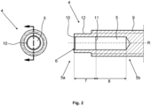
- Fig. 2 shows an embodiment of a connection shaft 4 for a drive unit 1 according to Fig. 1 .
- the receiving recess 5 extends coaxially to the axis of rotation R and the first portion 7 is arranged closer to the receiving opening 6 than the second portion 8.
- the chamfer 10 at the receiving opening 6 is formed with 30° x 0.09.
- the first portion 7 is arranged closer to the receiving opening 6 than the second portion 8.
- a chamfer 11 is formed between the first portion 7 and the second portion 8 at approximately 45°.
- the connection shaft 4 has a shoulder 12, in which the diameter corresponds approximately to the core diameter of the thread 9, and which partially surrounds the receiving recess 5. A radius is formed in the transition from the shoulder 12 to the thread 9.
- the invention is not limited to the embodiments shown and described, but also includes all embodiments having the same effect in the sense of the invention. It is expressly emphasized that the embodiments are not limited to all features in combination, rather each individual sub-feature may also have inventive significance in isolation from all other sub-features. Furthermore, the invention has not yet been limited to the combination of features defined in claim 1 either, but can also be defined by any other combination of certain features of all the individual features disclosed as a whole. This means that in principle virtually any individual feature of claim 1 can be omitted or replaced by at least one individual feature disclosed elsewhere in the application.
Landscapes
- Engineering & Computer Science (AREA)
- General Engineering & Computer Science (AREA)
- Mechanical Engineering (AREA)
- Shafts, Cranks, Connecting Bars, And Related Bearings (AREA)
- Connection Of Motors, Electrical Generators, Mechanical Devices, And The Like (AREA)
Applications Claiming Priority (1)
| Application Number | Priority Date | Filing Date | Title |
|---|---|---|---|
| US18/140,837 US20240360875A1 (en) | 2023-04-28 | 2023-04-28 | Drive unit and connection shaft for a drive unit |
Publications (1)
| Publication Number | Publication Date |
|---|---|
| EP4461982A1 true EP4461982A1 (de) | 2024-11-13 |
Family
ID=90720418
Family Applications (1)
| Application Number | Title | Priority Date | Filing Date |
|---|---|---|---|
| EP24169518.8A Pending EP4461982A1 (de) | 2023-04-28 | 2024-04-10 | Antriebseinheit und verbindungswelle für eine antriebseinheit |
Country Status (2)
| Country | Link |
|---|---|
| US (1) | US20240360875A1 (de) |
| EP (1) | EP4461982A1 (de) |
Citations (6)
| Publication number | Priority date | Publication date | Assignee | Title |
|---|---|---|---|---|
| CN100381715C (zh) * | 2003-08-13 | 2008-04-16 | 曼B与W狄赛尔公司 | 曲轴 |
| EP2233747A1 (de) * | 2009-03-10 | 2010-09-29 | Grundfos Management A/S | Mehrstufiges Kreiselpumpenaggregat |
| WO2011160240A1 (de) * | 2010-06-22 | 2011-12-29 | Jansen Ag | Wellenkörper mit einem abschnitt mit einer längsgerändelten aussenkontur |
| DE102016220901A1 (de) * | 2016-10-25 | 2018-04-26 | Zf Friedrichshafen Ag | Welle-Nabe-Verbund, Getriebe sowie Kraftfahrzeug |
| DE102020200351A1 (de) * | 2020-01-14 | 2021-07-15 | Robert Bosch Gesellschaft mit beschränkter Haftung | Kupplungseinheit |
| US20230366436A1 (en) * | 2021-03-15 | 2023-11-16 | Nsk Ltd. | Assembly of gear and rotating shaft, and assembly method therefor |
-
2023
- 2023-04-28 US US18/140,837 patent/US20240360875A1/en active Pending
-
2024
- 2024-04-10 EP EP24169518.8A patent/EP4461982A1/de active Pending
Patent Citations (6)
| Publication number | Priority date | Publication date | Assignee | Title |
|---|---|---|---|---|
| CN100381715C (zh) * | 2003-08-13 | 2008-04-16 | 曼B与W狄赛尔公司 | 曲轴 |
| EP2233747A1 (de) * | 2009-03-10 | 2010-09-29 | Grundfos Management A/S | Mehrstufiges Kreiselpumpenaggregat |
| WO2011160240A1 (de) * | 2010-06-22 | 2011-12-29 | Jansen Ag | Wellenkörper mit einem abschnitt mit einer längsgerändelten aussenkontur |
| DE102016220901A1 (de) * | 2016-10-25 | 2018-04-26 | Zf Friedrichshafen Ag | Welle-Nabe-Verbund, Getriebe sowie Kraftfahrzeug |
| DE102020200351A1 (de) * | 2020-01-14 | 2021-07-15 | Robert Bosch Gesellschaft mit beschränkter Haftung | Kupplungseinheit |
| US20230366436A1 (en) * | 2021-03-15 | 2023-11-16 | Nsk Ltd. | Assembly of gear and rotating shaft, and assembly method therefor |
Also Published As
| Publication number | Publication date |
|---|---|
| US20240360875A1 (en) | 2024-10-31 |
Similar Documents
| Publication | Publication Date | Title |
|---|---|---|
| US9964197B2 (en) | Standard gear unit, assembly kit and drive | |
| US10770934B2 (en) | Electrical machine | |
| US20060075838A1 (en) | Series of shafts and method for manufacturing the same | |
| US6500087B2 (en) | Electric motor with epicyclic gear system | |
| US20180069450A1 (en) | Rotary electric rotor and method of manufacturing rotary electric rotor | |
| US8262491B2 (en) | Driveshaft assembly and method for assembling driveshaft assembly | |
| US20160319879A1 (en) | Taper lock apparatus | |
| KR20070003963A (ko) | 센터링 핀 | |
| US20220410361A1 (en) | Power tool and two-speed gear assembly for a power tool | |
| EP3165796B1 (de) | Getriebemotor | |
| EP4461982A1 (de) | Antriebseinheit und verbindungswelle für eine antriebseinheit | |
| US5380118A (en) | Shaft coupling for bottom cylinders of drafting units on spinning machines | |
| CN113187877A (zh) | 一种用于高速重载斜齿轮传动系统的轴向力锥面止推结构 | |
| US20030056625A1 (en) | Output shaft and concentrically mounted attachments therefor | |
| US20160084293A1 (en) | Add-on drive shaft for an encoder or impeller fan and method for adding the shaft | |
| US12365021B2 (en) | Method for connecting two components, in particular a motor to a gearbox, and assembly with a connection between motor and gearbox | |
| US10415670B2 (en) | Worm drive | |
| EP1347212B1 (de) | Mehrstufiges Reduktionsgetriebe für Motoren | |
| CN105990919B (zh) | 基于分段磁钢和变截面轴的高速电机转子 | |
| KR20050061318A (ko) | 하이포이드 기어드 모터 및 모터 피니언과 하이포이드피니언과의 연결구조 | |
| CN210013987U (zh) | 一种电动推杆 | |
| CN114728665B (zh) | 用于轨道车辆的离合器 | |
| JP7114553B2 (ja) | モーターとピニオンギヤの締結構造及び方法 | |
| CN223306233U (zh) | 丝杠传动组件及使用其的减速齿轮箱 | |
| CN219372179U (zh) | 一种电机与减速机连接结构及机器人 |
Legal Events
| Date | Code | Title | Description |
|---|---|---|---|
| PUAI | Public reference made under article 153(3) epc to a published international application that has entered the european phase |
Free format text: ORIGINAL CODE: 0009012 |
|
| STAA | Information on the status of an ep patent application or granted ep patent |
Free format text: STATUS: THE APPLICATION HAS BEEN PUBLISHED |
|
| AK | Designated contracting states |
Kind code of ref document: A1 Designated state(s): AL AT BE BG CH CY CZ DE DK EE ES FI FR GB GR HR HU IE IS IT LI LT LU LV MC ME MK MT NL NO PL PT RO RS SE SI SK SM TR |
|
| STAA | Information on the status of an ep patent application or granted ep patent |
Free format text: STATUS: REQUEST FOR EXAMINATION WAS MADE |
|
| 17P | Request for examination filed |
Effective date: 20250513 |
|
| STAA | Information on the status of an ep patent application or granted ep patent |
Free format text: STATUS: EXAMINATION IS IN PROGRESS |
|
| 17Q | First examination report despatched |
Effective date: 20251006 |