EP4461678A1 - Fin assembling method - Google Patents
Fin assembling method Download PDFInfo
- Publication number
- EP4461678A1 EP4461678A1 EP23778789.0A EP23778789A EP4461678A1 EP 4461678 A1 EP4461678 A1 EP 4461678A1 EP 23778789 A EP23778789 A EP 23778789A EP 4461678 A1 EP4461678 A1 EP 4461678A1
- Authority
- EP
- European Patent Office
- Prior art keywords
- fin
- fins
- spot
- slit
- stacking
- Prior art date
- Legal status (The legal status is an assumption and is not a legal conclusion. Google has not performed a legal analysis and makes no representation as to the accuracy of the status listed.)
- Granted
Links
Images




Classifications
-
- F—MECHANICAL ENGINEERING; LIGHTING; HEATING; WEAPONS; BLASTING
- F28—HEAT EXCHANGE IN GENERAL
- F28F—DETAILS OF HEAT-EXCHANGE AND HEAT-TRANSFER APPARATUS, OF GENERAL APPLICATION
- F28F1/00—Tubular elements; Assemblies of tubular elements
- F28F1/10—Tubular elements and assemblies thereof with means for increasing heat-transfer area, e.g. with fins, with projections, with recesses
- F28F1/12—Tubular elements and assemblies thereof with means for increasing heat-transfer area, e.g. with fins, with projections, with recesses the means being only outside the tubular element
- F28F1/24—Tubular elements and assemblies thereof with means for increasing heat-transfer area, e.g. with fins, with projections, with recesses the means being only outside the tubular element and extending transversely
- F28F1/32—Tubular elements and assemblies thereof with means for increasing heat-transfer area, e.g. with fins, with projections, with recesses the means being only outside the tubular element and extending transversely the means having portions engaging further tubular elements
- F28F1/325—Fins with openings
-
- F—MECHANICAL ENGINEERING; LIGHTING; HEATING; WEAPONS; BLASTING
- F28—HEAT EXCHANGE IN GENERAL
- F28F—DETAILS OF HEAT-EXCHANGE AND HEAT-TRANSFER APPARATUS, OF GENERAL APPLICATION
- F28F3/00—Plate-like or laminated elements; Assemblies of plate-like or laminated elements
- F28F3/08—Elements constructed for building-up into stacks, e.g. capable of being taken apart for cleaning
-
- B—PERFORMING OPERATIONS; TRANSPORTING
- B21—MECHANICAL METAL-WORKING WITHOUT ESSENTIALLY REMOVING MATERIAL; PUNCHING METAL
- B21D—WORKING OR PROCESSING OF SHEET METAL OR METAL TUBES, RODS OR PROFILES WITHOUT ESSENTIALLY REMOVING MATERIAL; PUNCHING METAL
- B21D53/00—Making other particular articles
- B21D53/02—Making other particular articles heat exchangers or parts thereof, e.g. radiators, condensers fins, headers
- B21D53/022—Making the fins
- B21D53/025—Louvered fins
-
- B—PERFORMING OPERATIONS; TRANSPORTING
- B21—MECHANICAL METAL-WORKING WITHOUT ESSENTIALLY REMOVING MATERIAL; PUNCHING METAL
- B21D—WORKING OR PROCESSING OF SHEET METAL OR METAL TUBES, RODS OR PROFILES WITHOUT ESSENTIALLY REMOVING MATERIAL; PUNCHING METAL
- B21D53/00—Making other particular articles
- B21D53/02—Making other particular articles heat exchangers or parts thereof, e.g. radiators, condensers fins, headers
- B21D53/08—Making other particular articles heat exchangers or parts thereof, e.g. radiators, condensers fins, headers of both metal tubes and sheet metal
- B21D53/085—Making other particular articles heat exchangers or parts thereof, e.g. radiators, condensers fins, headers of both metal tubes and sheet metal with fins places on zig-zag tubes or parallel tubes
-
- B—PERFORMING OPERATIONS; TRANSPORTING
- B23—MACHINE TOOLS; METAL-WORKING NOT OTHERWISE PROVIDED FOR
- B23P—METAL-WORKING NOT OTHERWISE PROVIDED FOR; COMBINED OPERATIONS; UNIVERSAL MACHINE TOOLS
- B23P15/00—Making specific metal objects by operations not covered by a single other subclass or a group in this subclass
- B23P15/26—Making specific metal objects by operations not covered by a single other subclass or a group in this subclass heat exchangers or the like
-
- B—PERFORMING OPERATIONS; TRANSPORTING
- B21—MECHANICAL METAL-WORKING WITHOUT ESSENTIALLY REMOVING MATERIAL; PUNCHING METAL
- B21D—WORKING OR PROCESSING OF SHEET METAL OR METAL TUBES, RODS OR PROFILES WITHOUT ESSENTIALLY REMOVING MATERIAL; PUNCHING METAL
- B21D43/00—Feeding, positioning or storing devices combined with, or arranged in, or specially adapted for use in connection with, apparatus for working or processing sheet metal, metal tubes or metal profiles; Associations therewith of cutting devices
- B21D43/20—Storage arrangements; Piling or unpiling
- B21D43/22—Devices for piling sheets
-
- F—MECHANICAL ENGINEERING; LIGHTING; HEATING; WEAPONS; BLASTING
- F28—HEAT EXCHANGE IN GENERAL
- F28F—DETAILS OF HEAT-EXCHANGE AND HEAT-TRANSFER APPARATUS, OF GENERAL APPLICATION
- F28F2215/00—Fins
- F28F2215/12—Fins with U-shaped slots for laterally inserting conduits
Definitions
- the present disclosure relates to a method for stacking fins.
- Patent Document 1 discloses an apparatus for manufacturing a stack of fins for a heat exchanger.
- the apparatus can automatically perform the whole processes from the pressing of the fins for the heat exchanger to the taking out of the stack of the fins for the heat exchanger.
- multiple fins are vertically stacked.
- the fins on the upper portion of the stack are more unstable. Thus, it has been difficult to stack the fins very high.
- Patent Document 1 Japanese Patent No. 5594674
- the fins are manufactured at a manufacturing spot and sent to a stacking spot, the fins are vertically stacked to a certain height at the stacking spot. Then, a conveying process is performed to send the stacked fins to a next spot. If the multiple fins are vertically stacked as described above, stable stacking of the fins would be difficult, and thus the fins cannot be stacked so high. This shortens a time interval between the last conveying process and the next conveying process, increasing the frequency of the conveying process. The process of manufacturing the fins at the manufacturing spot is interrupted every time the conveying process is performed. Thus, if the fins cannot be stably stacked and the frequency of the conveying process increases, it would be difficult to operate a facility for manufacturing the fins continuously and stably.
- An object of the present disclosure is to allow stable stacking of the fins.
- a first aspect is directed to a method for stacking fins.
- a fin slit (13) for receiving a flat tube is formed in each of the fins (1).
- the method for stacking the fins includes arranging the fins (1) at a stacking spot (RA, RB, RC, RD) for the fins (1) with an opening (133) of the fin slit (13) facing upward or downward.
- the fins (1) can be stably stacked.
- a second aspect is an embodiment of the first aspect.
- the method further includes changing a position of the fin (1) with the opening (133) facing horizontally to a position with the opening (133) facing upward or downward.
- the fin (1) can be arranged with the opening (133) of the fin slit (13) facing upward or downward at the stacking spot (RA, RB, RC, RD) for the fins (1).
- a third aspect is an embodiment of the first or second aspect.
- the method further includes lifting up the fin (1).
- the fin (1) can be lifted up and sent to the stacking spot (RA).
- a fourth aspect is an embodiment of the first or second aspect.
- the method further includes dropping the fin (1) to make the opening (133) face downward.
- the fin (1) can be sent to the stacking spot (RB) by dropping the fin (1).
- a fifth aspect is an embodiment of the first or second aspect.
- the method further includes raising up the fin (1) to make the opening (133) face upward.
- the fins (1) can be stacked horizontally by raising up the fins (1).
- a sixth aspect is an embodiment of any one of the first to fifth aspects.
- the method further includes conveying the fin (1) manufactured at the manufacturing spot (P) for the fins (1) to separate the fin (1) from the manufacturing spot (P).
- the fins (1) can be kept from remaining in the manufacturing spot (P) for the fins (1), thereby allowing smooth manufacture of the fins (1).
- a seventh aspect is an embodiment of any one of the first to sixth aspects.
- the fins (1) are stacked with a support (R2) inserted into the fin slit (13).
- the fins (1) can be stacked while being supported by the support (R2).
- An eighth aspect is an embodiment of the seventh aspect.
- the fins (1) are stacked to be arranged in a direction of extension of the support (R2).
- the fins (1) can be stacked horizontally while being supported by the support (R2).
- a ninth aspect is an embodiment of any one of the first to eighth aspects.
- the method further includes stacking the fins (1) horizontally.
- the fins (1) can be stably stacked.
- FIG. 1 is a plan view of a fin (1) for a heat exchanger.
- the heat exchanger is provided in, for example, an indoor unit or outdoor unit of an air conditioner.
- the heat exchanger is a device that condenses or evaporates a refrigerant using air as a cooling source or a heating source, and is, for example, a component of a refrigerant circuit of a vapor compression refrigeration apparatus. Examples of the refrigerant circulating through the refrigerant circuit include a carbon dioxide refrigerant.
- the fin (1) includes a plurality of structural units (10).
- the structural units (10) are continuously arranged side by side in the X-axis direction.
- the structural unit (10) each include a plate-shaped portion (11), a continuous portion (12), a fin slit (13), a waffle portion (14), and fin tabs (15).
- the plate-shaped portion (11) is a plate-shaped member.
- the plate-shaped portions (11) are arranged side by side in the X-axis direction.
- the continuous portion (12) is provided between an adjacent pair of plate-shaped portions (11).
- the continuous portion (12) is a plate-shaped member.
- the continuous portion (12) is provided to be continuous with each of the adjacent plate-shaped portions (11).
- the continuous portion (12) has surfaces in the X-axis direction and Y-axis direction that are flush with each of the adjacent plate-shaped portions (11).
- the continuous portion (12) is located between the plate-shaped portions (11) adjacent to each other.
- the continuous portion (12) is located on the other side of the fin (1) in the Y-axis direction.
- the fin slit (13) is a space formed between the adjacent plate-shaped portions (11) and the continuous portion (12).
- the fin slit (13) extends in the Y-axis direction.
- the fin slit (13) is provided between the adjacent plate-shaped portions (11) on one side of the continuous portion (12) in the Y-axis direction.
- For the fin slit (13), one side and the other side in the X-axis direction are blocked by the plate-shaped portions (11), one side in the Y-axis direction is open, and the other side in the Y-axis direction is blocked by the continuous portion (12).
- the fin slit (13) includes a first slit portion (131) and a second slit portion (132).
- the first slit portion (131) is a portion of the fin slit (13) located on one side in the Y-axis direction.
- the second slit portion (132) is a portion of the fin slit (13) located on the other side in the Y-axis direction.
- the second slit portion (132) is continuous with the first slit portion (131) and extends from the first slit portion (131) toward the other side in the Y-axis direction.
- the fin slit (13) includes an opening (133) communicating with external space.
- the opening (133) is formed on one side of the first slit portion (131) in the Y-axis direction.
- a flat tube for sending a refrigerant is inserted into the fin slit (13).
- the dimension of the second slit portion (132) in the X-axis direction is set to match the dimension of the flat tube so that the flat tube can fit into the slit.
- the first slit portion (131) is configured to have a larger dimension than the second slit portion (132) in the X-axis direction so that the first slit portion (131) functions as a guide slit that guides the flat tube entering the fin slit (13). This allows easy insertion of the flat tube into the fin slit (13).
- the waffle portion (14) is provided on the plate-shaped portion (11), and is located at the center of the plate-shaped portion (11) in the Y-axis direction.
- the waffle portion (14) includes a raised portion and a non-raised portion.
- the raised portion is a portion raised in a thickness direction of the fin (1).
- the non-raised portion is a flat portion that is not raised in the thickness direction of the fin (1).
- the fin tabs (15) are provided to regulate an interval between the fins (1) adjacent to each other in the thickness direction, and are arranged on both sides of the waffle portion (14) in the Y-axis direction.
- the fin (1) has at least a plurality of fin slits (13).
- the fin (1) is manufactured by pressing a metal plate with a die at a manufacturing spot (P).
- the fin (1) just manufactured at the manufacturing spot (P) is arranged in a horizontal position (F).
- the fin (1) In the horizontal position (F), the fin (1) is laid down with the opening (133) of the fin slit (13) (see FIG. 1 ) facing horizontally.
- the position of the fin (1) is changed at a position changing spot (QA).
- the position of the fin slit (13) is changed from the horizontal position (F) to a downward position (G) at the position changing spot (QA).
- the fin (1) is placed with the opening (133) of the fin slit (13) facing downward in the vertical direction.
- a plurality of platforms (Q11) is arranged at the position changing spot (QA).
- the platforms (Q11) are arranged in line.
- a clearance (Q12) is present between the platforms (Q11) adjacent to each other.
- Second guide plates (Q14) are provided on each of the platforms (Q11).
- the fins (1) manufactured at the manufacturing spot (P) are conveyed in a conveying direction (E) while being separated by multiple first guide plates (Q13), and are sent onto the multiple platforms (Q 11).
- the following description will be made focusing on one of the fins (1).
- the fin (1) in the horizontal position (F) is arranged across the multiple platforms (Q11).
- the fin (1) is sandwiched between the second guide plates (Q14) from both sides on the platforms (Q11), thereby effectively keeping the fin (1) on the platforms (Q11).
- any of the fin slits (13) is located above the clearance (Q12) between the platforms (Q11) and faces the clearance (Q12) in the vertical direction.
- a plate-shaped or linear moving member (Q15) is disposed below the clearance (Q12) between the platforms (Q11).
- the moving member (Q15) rises from below the clearance (Q12) to pass through the clearance (Q12).
- the moving member (Q15) passes through the clearance (Q12) and approaches the fin slit (13) of the fin (1) from below to lift up the fin (1).
- the fin (1) rotates about a point of contact between the moving member (Q15) and the fin slit (13) so that the opening (133) of the fin slit (13) faces downward.
- the moving member (Q15) enters the fin slit (13), and the position of the fin (1) is changed from the horizontal position (F) to the downward position (G). As a result, the moving member (Q15) is caught in the fin slit (13).
- the moving member (Q15) When the moving member (Q15) is caught in the fin slit (13), the moving member (Q15) makes contact with the bottom of the fin slit (13) of the fin (1) in the downward position (G) from below, thereby supporting the fin (1) from below.
- the moving member (Q15) caught in the fin slit (13) moves, the fin (1) kept in the downward position (G) moves together with the moving member (Q15).
- a tray (R1) for stacking the fins (1) is disposed at the stacking spot (RA) for the fins (1).
- the tray (R1) is a rectangular frame-shaped member with open top and bottom.
- the tray (R1) is provided with a plurality of supports (R2).
- the supports (R2) are arranged in parallel at intervals and extend horizontally.
- Each of the supports (R2) is a plate-shaped or linear member that can enter the fin slit (13).
- the moving member (Q15) moves to the stacking spot (RA) for the fins (1) while supporting the fins (1) in the downward position (G).
- the fins (1) are transferred from the moving member (Q15) onto the supports (R2).
- the supports (R2) When the fins (1) are transferred from the moving member (Q15) onto the supports (R2), the supports (R2) enter the fin slits (13) to be caught in the fin slits (13). As a result, the fins (1) kept in the downward position (G) are supported by the supports (R2).
- the fins (1) are stacked to be arranged in a direction (V) of extension of the supports (R2).
- the fins (1) are horizontally stacked at the stacking spot (RA).
- the horizontal stacking of the fins (1) means that the fins (1) in the downward position (G) or an upward position (H) are arranged side by side, with the fin slits (13) of the adjacent fins (1) overlapping each other when viewed from the direction (V) of arrangement of the fins (1).
- the position changing spot (QB) for the fins (1) is provided with a first guide (Q21), a first bed (Q22), a second bed (Q23), and a third bed (Q24).
- the first guide (Q21) is a hollow member and is shaped to extend in the vertical direction.
- the first bed (Q22), the second bed (Q23), and the third bed (Q24) are provided in the first guide (Q21).
- An opening (Q25) is formed at the bottom of the first guide (Q21) so that the inside and outside of the first guide (Q21) communicate with each other.
- the first bed (Q22) is rotatably supported.
- the first bed (Q22) is a plate-shaped member.
- the first bed (Q22) includes a first placement surface (Q221) on which the fin (1) manufactured at the manufacturing spot (P) (see FIG. 2 ) is placed.
- the first bed (Q22) includes a center portion (Q222) which is the center of rotation and a rotating end portion (Q223) which rotates about the center portion (Q222).
- the position of the first bed (Q22) is changed to any one of a horizontal position (S1) or an inclined position (S2).
- the first placement surface (Q221) of the first bed (Q22) is parallel to the horizontal direction (J).
- the first placement surface (Q221) of the first bed (Q22) is inclined downward with respect to one side (J1) in the horizontal direction (J).
- the second bed (Q23) is placed below the first bed (Q22).
- the second bed (Q23) is a plate-shaped member inclined downward with respect to the one side (J1) in the horizontal direction (J) and has a second placement surface (Q231).
- the third bed (Q24) is placed below the second bed (Q23).
- the third bed (Q24) is a plate-shaped member.
- the third bed (Q24) is rotatably supported.
- the position of the third bed (Q24) is changed to any one of an inclined position (T1) or a vertical position (T2).
- a third placement surface (Q241) of the third bed (Q24) is inclined downward with respect to the one side (J1) in the horizontal direction (J).
- the third placement surface (Q241) of the third bed (Q24) is parallel to the vertical direction.
- the supports (R2) are disposed at a stacking spot (RB) for the fins (1).
- the supports (R2) are placed below the opening (Q25) of the first guide (Q21).
- the fin (1) manufactured at the manufacturing spot (P) (see FIG. 2 ) is placed in the horizontal position (F) on the first placement surface (Q221) of the first bed (Q22) in the horizontal position (S1) at the position changing spot (QB).
- a state in which the fin (1) in the horizontal position (F) is placed on the first placement surface (Q221) of the first bed (Q22) in the horizontal position (S1) may be referred to as a horizontally placed state.
- the continuous portion (12) of the fin (1) is located near the center portion (Q222) of the first bed (Q22), and the opening (133) of the fin slit (13) is located near the rotating end portion (Q223) of the first bed (Q22).
- the fin (1) manufactured at the manufacturing spot (P) is placed on the first placement surface (Q221) of the first bed (Q22) to be in the horizontally placed state, the position of the first bed (Q22) is changed to the inclined position (S2).
- the fin (1) slides down the first placement surface (Q221).
- the fin (1) slides down the first placement surface (Q221) with the opening (133) of the fin slit (13) facing down.
- the fin (1) slides down the first placement surface (Q221), falls off the first bed (Q22), lands on the second bed (Q23), and slides down the second placement surface (Q231) of the second bed (Q23).
- the fin (1) slides down the second placement surface (Q231), falls off the second bed (Q23), and lands on the third bed (Q24) to be placed on the third placement surface (Q241) of the third bed (Q24).
- the position of the third bed (Q24) is changed from the inclined position (T1) to the vertical position (T2).
- the fin (1) falls off the third bed (Q24) in the downward position (G) with the opening (133) of the fin slit (13) facing downward.
- the fin (1) that has fallen off the third bed (Q24) reaches the stacking spot (RB).
- the fin (1) falls in the downward position (G), and the supports (R2) enter the fin slits (13) through the openings (133) and are caught in the fin slits (13).
- the fins (1) are horizontally stacked in the downward position (G) at the stacking spot (RB) as in the first stacking example (see FIG. 3 ).
- an inclined surface (Q3) inclined downward with respect to the horizontal direction is provided at a position changing spot (QC) for the fins (1).
- Multiple supports (R2) are provided at the bottom of the inclined surface (Q3).
- the fin (1) manufactured at the manufacturing spot (P) is disposed in the horizontal position (F) above the inclined surface (Q3) with the opening (133) of the fin slit (13) facing the inclined surface (Q3).
- the fin (1) placed above the inclined surface (Q3) slides down the inclined surface (Q3) when pushed toward the inclined surface (Q3) by an arm member (not shown).
- the fin (1) is inclined along the inclined surface (Q3) when sliding down the inclined surface (Q3), and thus the position of the fin (1) is changed to make the opening (133) of the fin slit (13) face downward.
- the fin (1) slides down the inclined surface (Q3) with the opening (133) of the fin slit (13) facing downward.
- the fin (1) that has reached the bottom of the inclined surface (Q3) moves toward the multiple supports (R2) from the opening (133) side.
- any of the supports (R2) enters the fin slit (13) through the opening (133) and is caught in the fin slit (13), supporting the fin (1) in the downward position (G).
- the fins (1) are horizontally stacked in the downward position (G) at the stacking spot (RC) as in the first stacking example (see FIG. 3 ).
- a rotary platform (Q4) is placed at a position changing spot (QD) for the fins (1).
- a stacking spot (RD) for the fins (1) is provided with a stacking platform (R3) and a plurality of supports (R2).
- the rotary platform (Q4) is rotatably supported with the fin (1) placed thereon.
- the stacking platform (R3) is a plate-shaped member on which the stacked fins (1) are placed.
- the rotary platform (Q4) is arranged near the stacking platform (R3).
- the supports (R2) are disposed above the stacking platform (R3).
- the supports (R2) are arranged in parallel at intervals.
- the fin (1) manufactured at the manufacturing spot (P) (see FIG. 1 ) is placed in the horizontal position (F) on the rotary platform (Q4).
- the rotary platform (Q4) rotates with the fin (1) in the horizontal position (F) placed thereon.
- the fin (1) rotates together with the rotary platform (Q4).
- the fin (1) is raised up when the rotary platform (Q4) rotates, and the position of the fin (1) is changed from the horizontal position (F) to an upward position (H).
- the opening (133) of the fin slit (13) faces upward in the vertical direction.
- the fin (1) in the upward position (H) is pushed out of the rotary platform (Q4) toward the stacking spot (RD) by an arm member (not shown).
- any of the supports (R2) enters the fin slit (13) and is caught in the fin slit (13), and the fin (1) in the upward position (H) is placed on the stacking platform (R3).
- the fins (1) are horizontally stacked in the upward position (H) at the stacking spot (RD).
- the fins (1) are arranged at the stacking spot (RA) for the fins (1) with the openings (133) of the fin slits (13) facing upward or downward.
- the fins (1) can be horizontally stacked. This allows the multiple fins (1) to be stacked more stably than when the fins (1) are vertically stacked, thereby allowing more fins (1) to be stacked stably. As a result, the conveying process is performed less frequently, thereby allowing stable operation of a manufacturing facility for the fins (1).
- the present disclosure is useful for a method for stacking fins.
Landscapes
- Engineering & Computer Science (AREA)
- Mechanical Engineering (AREA)
- Physics & Mathematics (AREA)
- Thermal Sciences (AREA)
- General Engineering & Computer Science (AREA)
- Geometry (AREA)
- Cooling Or The Like Of Electrical Apparatus (AREA)
- Attitude Control For Articles On Conveyors (AREA)
- Feeding Of Articles To Conveyors (AREA)
- Automatic Assembly (AREA)
- Cooling Or The Like Of Semiconductors Or Solid State Devices (AREA)
Abstract
Description
- The present disclosure relates to a method for stacking fins.
-
Patent Document 1 discloses an apparatus for manufacturing a stack of fins for a heat exchanger. The apparatus can automatically perform the whole processes from the pressing of the fins for the heat exchanger to the taking out of the stack of the fins for the heat exchanger. Previously, multiple fins are vertically stacked. However, when the fins are stacked too high, the fins on the upper portion of the stack are more unstable. Thus, it has been difficult to stack the fins very high. - Patent Document 1:
Japanese Patent No. 5594674 - After the fins are manufactured at a manufacturing spot and sent to a stacking spot, the fins are vertically stacked to a certain height at the stacking spot. Then, a conveying process is performed to send the stacked fins to a next spot. If the multiple fins are vertically stacked as described above, stable stacking of the fins would be difficult, and thus the fins cannot be stacked so high. This shortens a time interval between the last conveying process and the next conveying process, increasing the frequency of the conveying process. The process of manufacturing the fins at the manufacturing spot is interrupted every time the conveying process is performed. Thus, if the fins cannot be stably stacked and the frequency of the conveying process increases, it would be difficult to operate a facility for manufacturing the fins continuously and stably.
- An object of the present disclosure is to allow stable stacking of the fins.
- A first aspect is directed to a method for stacking fins. A fin slit (13) for receiving a flat tube is formed in each of the fins (1). The method for stacking the fins includes arranging the fins (1) at a stacking spot (RA, RB, RC, RD) for the fins (1) with an opening (133) of the fin slit (13) facing upward or downward.
- In the first aspect, the fins (1) can be stably stacked.
- A second aspect is an embodiment of the first aspect. In the second aspect, the method further includes changing a position of the fin (1) with the opening (133) facing horizontally to a position with the opening (133) facing upward or downward.
- In the second aspect, the fin (1) can be arranged with the opening (133) of the fin slit (13) facing upward or downward at the stacking spot (RA, RB, RC, RD) for the fins (1).
- A third aspect is an embodiment of the first or second aspect. In the third aspect, the method further includes lifting up the fin (1).
- In the third aspect, the fin (1) can be lifted up and sent to the stacking spot (RA).
- A fourth aspect is an embodiment of the first or second aspect. In the fourth aspect, the method further includes dropping the fin (1) to make the opening (133) face downward.
- In the fourth aspect, the fin (1) can be sent to the stacking spot (RB) by dropping the fin (1).
- A fifth aspect is an embodiment of the first or second aspect. In the fifth aspect, the method further includes raising up the fin (1) to make the opening (133) face upward.
- In the fifth aspect, the fins (1) can be stacked horizontally by raising up the fins (1).
- A sixth aspect is an embodiment of any one of the first to fifth aspects. In the sixth aspect, the method further includes conveying the fin (1) manufactured at the manufacturing spot (P) for the fins (1) to separate the fin (1) from the manufacturing spot (P).
- In the sixth aspect, the fins (1) can be kept from remaining in the manufacturing spot (P) for the fins (1), thereby allowing smooth manufacture of the fins (1).
- A seventh aspect is an embodiment of any one of the first to sixth aspects. In the seventh aspect, the fins (1) are stacked with a support (R2) inserted into the fin slit (13).
- In the seventh aspect, the fins (1) can be stacked while being supported by the support (R2).
- An eighth aspect is an embodiment of the seventh aspect. In the eighth aspect, the fins (1) are stacked to be arranged in a direction of extension of the support (R2).
- In the eighth aspect, the fins (1) can be stacked horizontally while being supported by the support (R2).
- A ninth aspect is an embodiment of any one of the first to eighth aspects. In the ninth aspect, the method further includes stacking the fins (1) horizontally.
- In the ninth aspect, the fins (1) can be stably stacked.
-
-
FIG. 1 is a plan view of a fin according to an embodiment. -
FIG. 2 is a schematic view of a configuration for changing the position of the fins that have been manufactured. -
FIG. 3 is a schematic view of a configuration for stacking the fins that have changed the position. -
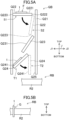
FIG. 4A is a perspective view of a first bed.FIG. 4B is a perspective view of a third bed.FIG. 4C is a perspective view of a support. -
FIG. 5A is a schematic view of a configuration of a position changing spot for the fins and a stacking spot for the fins.FIG. 5B is a side view of the support. -
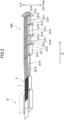
FIG. 6 is a perspective view of a configuration of a position changing spot for the fins and a stacking spot for the fins. -
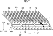
FIG. 7 is a perspective view of a configuration of a position changing spot for the fins and a stacking spot for the fins. - Embodiments of the present disclosure will be described in detail below with reference to the drawings. The present disclosure is not limited to the embodiments shown below, and various changes can be made within the scope without departing from the technical concept of the present disclosure. Each of the drawings is intended to illustrate the present disclosure conceptually, and dimensions, ratios, or numbers may be exaggerated or simplified as necessary for the sake of ease of understanding.
- An exemplary embodiment will be described in detail below with reference to the drawings.
-
FIG. 1 is a plan view of a fin (1) for a heat exchanger. InFIG. 1 , an X-axis direction and a Y-axis direction are perpendicular to each other. The heat exchanger is provided in, for example, an indoor unit or outdoor unit of an air conditioner. The heat exchanger is a device that condenses or evaporates a refrigerant using air as a cooling source or a heating source, and is, for example, a component of a refrigerant circuit of a vapor compression refrigeration apparatus. Examples of the refrigerant circulating through the refrigerant circuit include a carbon dioxide refrigerant. - The fin (1) includes a plurality of structural units (10). The structural units (10) are continuously arranged side by side in the X-axis direction. The structural unit (10) each include a plate-shaped portion (11), a continuous portion (12), a fin slit (13), a waffle portion (14), and fin tabs (15).
- The plate-shaped portion (11) is a plate-shaped member. The plate-shaped portions (11) are arranged side by side in the X-axis direction. The continuous portion (12) is provided between an adjacent pair of plate-shaped portions (11).
- The continuous portion (12) is a plate-shaped member. The continuous portion (12) is provided to be continuous with each of the adjacent plate-shaped portions (11). The continuous portion (12) has surfaces in the X-axis direction and Y-axis direction that are flush with each of the adjacent plate-shaped portions (11). The continuous portion (12) is located between the plate-shaped portions (11) adjacent to each other. The continuous portion (12) is located on the other side of the fin (1) in the Y-axis direction.
- The fin slit (13) is a space formed between the adjacent plate-shaped portions (11) and the continuous portion (12). The fin slit (13) extends in the Y-axis direction. The fin slit (13) is provided between the adjacent plate-shaped portions (11) on one side of the continuous portion (12) in the Y-axis direction. For the fin slit (13), one side and the other side in the X-axis direction are blocked by the plate-shaped portions (11), one side in the Y-axis direction is open, and the other side in the Y-axis direction is blocked by the continuous portion (12). The fin slit (13) includes a first slit portion (131) and a second slit portion (132). The first slit portion (131) is a portion of the fin slit (13) located on one side in the Y-axis direction. The second slit portion (132) is a portion of the fin slit (13) located on the other side in the Y-axis direction. The second slit portion (132) is continuous with the first slit portion (131) and extends from the first slit portion (131) toward the other side in the Y-axis direction. The fin slit (13) includes an opening (133) communicating with external space. The opening (133) is formed on one side of the first slit portion (131) in the Y-axis direction.
- A flat tube for sending a refrigerant is inserted into the fin slit (13). The dimension of the second slit portion (132) in the X-axis direction is set to match the dimension of the flat tube so that the flat tube can fit into the slit. The first slit portion (131) is configured to have a larger dimension than the second slit portion (132) in the X-axis direction so that the first slit portion (131) functions as a guide slit that guides the flat tube entering the fin slit (13). This allows easy insertion of the flat tube into the fin slit (13).
- The waffle portion (14) is provided on the plate-shaped portion (11), and is located at the center of the plate-shaped portion (11) in the Y-axis direction. The waffle portion (14) includes a raised portion and a non-raised portion. The raised portion is a portion raised in a thickness direction of the fin (1). The non-raised portion is a flat portion that is not raised in the thickness direction of the fin (1).
- The fin tabs (15) are provided to regulate an interval between the fins (1) adjacent to each other in the thickness direction, and are arranged on both sides of the waffle portion (14) in the Y-axis direction.
- There is no particular limitations on the other features of the fin (1) as long as the fin (1) has at least a plurality of fin slits (13).
- A first embodiment of the method for stacking the fins (1) will be described below.
- The fin (1) is manufactured by pressing a metal plate with a die at a manufacturing spot (P). In the first embodiment, the fin (1) just manufactured at the manufacturing spot (P) is arranged in a horizontal position (F).
- In the horizontal position (F), the fin (1) is laid down with the opening (133) of the fin slit (13) (see
FIG. 1 ) facing horizontally. - The position of the fin (1) is changed at a position changing spot (QA).
- In the first embodiment, the position of the fin slit (13) is changed from the horizontal position (F) to a downward position (G) at the position changing spot (QA). In the downward position (G), the fin (1) is placed with the opening (133) of the fin slit (13) facing downward in the vertical direction.
- A plurality of platforms (Q11) is arranged at the position changing spot (QA). The platforms (Q11) are arranged in line. A clearance (Q12) is present between the platforms (Q11) adjacent to each other.
- Second guide plates (Q14) are provided on each of the platforms (Q11).
- The fins (1) manufactured at the manufacturing spot (P) are conveyed in a conveying direction (E) while being separated by multiple first guide plates (Q13), and are sent onto the multiple platforms (Q 11). The following description will be made focusing on one of the fins (1).
- The fin (1) in the horizontal position (F) is arranged across the multiple platforms (Q11). The fin (1) is sandwiched between the second guide plates (Q14) from both sides on the platforms (Q11), thereby effectively keeping the fin (1) on the platforms (Q11).
- When the fin (1) in the horizontal position (F) is placed across the multiple platforms (Q11), any of the fin slits (13) (see
FIG. 1 ) is located above the clearance (Q12) between the platforms (Q11) and faces the clearance (Q12) in the vertical direction. - A plate-shaped or linear moving member (Q15) is disposed below the clearance (Q12) between the platforms (Q11).
- As illustrated in
FIGS. 2 and3 , when the fin (1) in the horizontal position (F) is placed across the platforms (Q11), the moving member (Q15) rises from below the clearance (Q12) to pass through the clearance (Q12). The moving member (Q15) passes through the clearance (Q12) and approaches the fin slit (13) of the fin (1) from below to lift up the fin (1). When the moving member (Q15) lifts up the fin (1), the fin (1) rotates about a point of contact between the moving member (Q15) and the fin slit (13) so that the opening (133) of the fin slit (13) faces downward. Thus, the moving member (Q15) enters the fin slit (13), and the position of the fin (1) is changed from the horizontal position (F) to the downward position (G). As a result, the moving member (Q15) is caught in the fin slit (13). - When the moving member (Q15) is caught in the fin slit (13), the moving member (Q15) makes contact with the bottom of the fin slit (13) of the fin (1) in the downward position (G) from below, thereby supporting the fin (1) from below. When the moving member (Q15) caught in the fin slit (13) moves, the fin (1) kept in the downward position (G) moves together with the moving member (Q15).
- A tray (R1) for stacking the fins (1) is disposed at the stacking spot (RA) for the fins (1). The tray (R1) is a rectangular frame-shaped member with open top and bottom. The tray (R1) is provided with a plurality of supports (R2). The supports (R2) are arranged in parallel at intervals and extend horizontally. Each of the supports (R2) is a plate-shaped or linear member that can enter the fin slit (13).
- The moving member (Q15) moves to the stacking spot (RA) for the fins (1) while supporting the fins (1) in the downward position (G). The fins (1) are transferred from the moving member (Q15) onto the supports (R2).
- When the fins (1) are transferred from the moving member (Q15) onto the supports (R2), the supports (R2) enter the fin slits (13) to be caught in the fin slits (13). As a result, the fins (1) kept in the downward position (G) are supported by the supports (R2).
- In the stacking spot (RA), the fins (1) are stacked to be arranged in a direction (V) of extension of the supports (R2).
- The fins (1) are horizontally stacked at the stacking spot (RA). The horizontal stacking of the fins (1) means that the fins (1) in the downward position (G) or an upward position (H) are arranged side by side, with the fin slits (13) of the adjacent fins (1) overlapping each other when viewed from the direction (V) of arrangement of the fins (1).
- A second embodiment of the method for stacking the fins (1) will be described below.
- As illustrated in
FIG. 5A , the position changing spot (QB) for the fins (1) is provided with a first guide (Q21), a first bed (Q22), a second bed (Q23), and a third bed (Q24). - As illustrated in
FIGS. 4A and5A , the first guide (Q21) is a hollow member and is shaped to extend in the vertical direction. The first bed (Q22), the second bed (Q23), and the third bed (Q24) are provided in the first guide (Q21). An opening (Q25) is formed at the bottom of the first guide (Q21) so that the inside and outside of the first guide (Q21) communicate with each other. - The first bed (Q22) is rotatably supported. The first bed (Q22) is a plate-shaped member. The first bed (Q22) includes a first placement surface (Q221) on which the fin (1) manufactured at the manufacturing spot (P) (see
FIG. 2 ) is placed. The first bed (Q22) includes a center portion (Q222) which is the center of rotation and a rotating end portion (Q223) which rotates about the center portion (Q222). - When the first bed (Q22) rotates, the position of the first bed (Q22) is changed to any one of a horizontal position (S1) or an inclined position (S2). In the horizontal position (S1), the first placement surface (Q221) of the first bed (Q22) is parallel to the horizontal direction (J). In the inclined position (S2), the first placement surface (Q221) of the first bed (Q22) is inclined downward with respect to one side (J1) in the horizontal direction (J).
- As illustrated in
FIG. 5A , the second bed (Q23) is placed below the first bed (Q22). The second bed (Q23) is a plate-shaped member inclined downward with respect to the one side (J1) in the horizontal direction (J) and has a second placement surface (Q231). - As illustrated in
FIGS. 4A and5A , the third bed (Q24) is placed below the second bed (Q23). The third bed (Q24) is a plate-shaped member. The third bed (Q24) is rotatably supported. When the third bed (Q24) rotates, the position of the third bed (Q24) is changed to any one of an inclined position (T1) or a vertical position (T2). In the inclined position (T1), a third placement surface (Q241) of the third bed (Q24) is inclined downward with respect to the one side (J1) in the horizontal direction (J). In the vertical position (T2), the third placement surface (Q241) of the third bed (Q24) is parallel to the vertical direction. - As illustrated in
FIG. 5A , the supports (R2) are disposed at a stacking spot (RB) for the fins (1). The supports (R2) are placed below the opening (Q25) of the first guide (Q21). - As illustrated in
FIGS. 4A and5A , the fin (1) manufactured at the manufacturing spot (P) (seeFIG. 2 ) is placed in the horizontal position (F) on the first placement surface (Q221) of the first bed (Q22) in the horizontal position (S1) at the position changing spot (QB). - In the following description, a state in which the fin (1) in the horizontal position (F) is placed on the first placement surface (Q221) of the first bed (Q22) in the horizontal position (S1) may be referred to as a horizontally placed state.
- When the fin (1) is in the horizontally placed state, the continuous portion (12) of the fin (1) is located near the center portion (Q222) of the first bed (Q22), and the opening (133) of the fin slit (13) is located near the rotating end portion (Q223) of the first bed (Q22).
- When the fin (1) manufactured at the manufacturing spot (P) is placed on the first placement surface (Q221) of the first bed (Q22) to be in the horizontally placed state, the position of the first bed (Q22) is changed to the inclined position (S2). When the position of the first bed (Q22) is changed to the inclined position (S2), the fin (1) slides down the first placement surface (Q221). The fin (1) slides down the first placement surface (Q221) with the opening (133) of the fin slit (13) facing down.
- The fin (1) slides down the first placement surface (Q221), falls off the first bed (Q22), lands on the second bed (Q23), and slides down the second placement surface (Q231) of the second bed (Q23).
- As illustrated in
FIGS. 4B and5A , the fin (1) slides down the second placement surface (Q231), falls off the second bed (Q23), and lands on the third bed (Q24) to be placed on the third placement surface (Q241) of the third bed (Q24). - When the fin (1) is placed on the third placement surface (Q241) of the third bed (Q24), the position of the third bed (Q24) is changed from the inclined position (T1) to the vertical position (T2). Thus, the fin (1) falls off the third bed (Q24) in the downward position (G) with the opening (133) of the fin slit (13) facing downward.
- As illustrated in
FIGS. 4C ,5A, and 5B , the fin (1) that has fallen off the third bed (Q24) reaches the stacking spot (RB). At this time, the fin (1) falls in the downward position (G), and the supports (R2) enter the fin slits (13) through the openings (133) and are caught in the fin slits (13). - When the process of changing the position of the fin (1) at the position changing spot (QB) is performed as in the second variation for the multiple fins (1), the fins (1) are horizontally stacked in the downward position (G) at the stacking spot (RB) as in the first stacking example (see
FIG. 3 ). - A third embodiment of the method for stacking the fins (1) will be described below.
- As illustrated in
FIG. 6 , an inclined surface (Q3) inclined downward with respect to the horizontal direction is provided at a position changing spot (QC) for the fins (1). Multiple supports (R2) are provided at the bottom of the inclined surface (Q3). - The fin (1) manufactured at the manufacturing spot (P) (see
FIG. 2 ) is disposed in the horizontal position (F) above the inclined surface (Q3) with the opening (133) of the fin slit (13) facing the inclined surface (Q3). The fin (1) placed above the inclined surface (Q3) slides down the inclined surface (Q3) when pushed toward the inclined surface (Q3) by an arm member (not shown). The fin (1) is inclined along the inclined surface (Q3) when sliding down the inclined surface (Q3), and thus the position of the fin (1) is changed to make the opening (133) of the fin slit (13) face downward. The fin (1) slides down the inclined surface (Q3) with the opening (133) of the fin slit (13) facing downward. The fin (1) that has reached the bottom of the inclined surface (Q3) moves toward the multiple supports (R2) from the opening (133) side. As a result, any of the supports (R2) enters the fin slit (13) through the opening (133) and is caught in the fin slit (13), supporting the fin (1) in the downward position (G). - When the process of changing the position of the fin (1) by dropping the fin (1) using the inclined surface (Q3) at the position changing spot (QC) is performed as in the third variation for the multiple fins (1), the fins (1) are horizontally stacked in the downward position (G) at the stacking spot (RC) as in the first stacking example (see
FIG. 3 ). - A fourth embodiment of the method for stacking the fins (1) will be described below.
- A fourth embodiment of the method for stacking the fins (1) will be described below.
- As illustrated in
FIG. 7 , a rotary platform (Q4) is placed at a position changing spot (QD) for the fins (1). A stacking spot (RD) for the fins (1) is provided with a stacking platform (R3) and a plurality of supports (R2). - The rotary platform (Q4) is rotatably supported with the fin (1) placed thereon. The stacking platform (R3) is a plate-shaped member on which the stacked fins (1) are placed. The rotary platform (Q4) is arranged near the stacking platform (R3). The supports (R2) are disposed above the stacking platform (R3). The supports (R2) are arranged in parallel at intervals.
- The fin (1) manufactured at the manufacturing spot (P) (see
FIG. 1 ) is placed in the horizontal position (F) on the rotary platform (Q4). The rotary platform (Q4) rotates with the fin (1) in the horizontal position (F) placed thereon. The fin (1) rotates together with the rotary platform (Q4). The fin (1) is raised up when the rotary platform (Q4) rotates, and the position of the fin (1) is changed from the horizontal position (F) to an upward position (H). - When the fin (1) is in the upward position (H), the opening (133) of the fin slit (13) faces upward in the vertical direction.
- The fin (1) in the upward position (H) is pushed out of the rotary platform (Q4) toward the stacking spot (RD) by an arm member (not shown). As a result, any of the supports (R2) enters the fin slit (13) and is caught in the fin slit (13), and the fin (1) in the upward position (H) is placed on the stacking platform (R3).
- When the process of changing the position of the fin (1) by raising up the fin (1) using the rotary platform (Q4) at the position changing spot (QD) is performed as in the fourth variation for the multiple fins (1), the fins (1) are horizontally stacked in the upward position (H) at the stacking spot (RD).
- As described above, the fins (1) are arranged at the stacking spot (RA) for the fins (1) with the openings (133) of the fin slits (13) facing upward or downward. Thus, the fins (1) can be horizontally stacked. This allows the multiple fins (1) to be stacked more stably than when the fins (1) are vertically stacked, thereby allowing more fins (1) to be stacked stably. As a result, the conveying process is performed less frequently, thereby allowing stable operation of a manufacturing facility for the fins (1).
- While the embodiments and the variations thereof have been described above, it will be understood that various changes in form and details may be made without departing from the spirit and scope of the claims (e.g., (1) below). The embodiments, the variation thereof, and the other embodiments may be combined and replaced with each other without deteriorating intended functions of the present disclosure.
- (1) In the first to fourth embodiments, the position changing spot (QA, QB, QC, QD) for the fins (1) may be separated from the manufacturing spot (P) for the fins (1), and the fins (1) manufactured at the manufacturing spot (P) may be conveyed to the position changing spot (QA, QB, QC, QD) by separating the fins (1) from the manufacturing spot (P) using a conveying member such as a conveyor. This can keep the fins (1) from remaining in the manufacturing spot (P) for the fins (1), thereby allowing smooth manufacture of the fins (1).
- As can be seen from the foregoing description, the present disclosure is useful for a method for stacking fins.
-
- 1 Fin
- 13 Fin Slit
- 133 Opening of Fin Slit
- P Manufacturing Spot for Fin
- R2 Support
- RA, RB, RC, RD Stacking Spot for Fin
- QA, QB, QC, QD Position Changing Spot for Fin
Claims (9)
- A method for stacking fins (1) each having a fin slit (13) for receiving a flat tube, the method comprising:
arranging each of the fins (1) at a stacking spot (RA, RB, RC, RD) for the fins (1) with an opening (133) of the fin slit (13) facing upward or downward. - The method of claim 1, further comprising:
changing a position of the fin (1) with the opening (133) facing horizontally to a position with the opening (133) facing upward or downward. - The method of claim 1 or 2, further comprising:
lifting up the fin (1). - The method of claim 1 or 2, further comprising:
dropping the fin (1) to make the opening (133) face downward. - The method of claim 1 or 2, further comprising:
raising up the fin (1) to make the opening (133) face upward. - The method of any one of claims 1 to 5, further comprising:
conveying the fin (1) manufactured at the manufacturing spot (P) for the fins (1) to separate the fin (1) from the manufacturing spot (P). - The method of any one of claims 1 to 6, wherein
the fins (1) are stacked with a support (R2) inserted into the fin slit (13). - The method of claim 7, wherein
the fins (1) are stacked to be arranged in a direction of extension of the support (R2). - The method of any one of claims 1 to 8, further comprising:
stacking the fins (1) horizontally.
Priority Applications (1)
| Application Number | Priority Date | Filing Date | Title |
|---|---|---|---|
| EP25224340.7A EP4706877A3 (en) | 2022-03-31 | 2023-01-25 | Fin assembling method |
Applications Claiming Priority (2)
| Application Number | Priority Date | Filing Date | Title |
|---|---|---|---|
| JP2022060684A JP7417140B2 (en) | 2022-03-31 | 2022-03-31 | Fin accumulation method |
| PCT/JP2023/002279 WO2023188751A1 (en) | 2022-03-31 | 2023-01-25 | Fin assembling method |
Related Child Applications (2)
| Application Number | Title | Priority Date | Filing Date |
|---|---|---|---|
| EP25224340.7A Division EP4706877A3 (en) | 2022-03-31 | 2023-01-25 | Fin assembling method |
| EP25224340.7A Division-Into EP4706877A3 (en) | 2022-03-31 | 2023-01-25 | Fin assembling method |
Publications (3)
| Publication Number | Publication Date |
|---|---|
| EP4461678A1 true EP4461678A1 (en) | 2024-11-13 |
| EP4461678A4 EP4461678A4 (en) | 2025-05-28 |
| EP4461678B1 EP4461678B1 (en) | 2026-05-06 |
Family
ID=88200246
Family Applications (2)
| Application Number | Title | Priority Date | Filing Date |
|---|---|---|---|
| EP23778789.0A Active EP4461678B1 (en) | 2022-03-31 | 2023-01-25 | Fin assembling method |
| EP25224340.7A Pending EP4706877A3 (en) | 2022-03-31 | 2023-01-25 | Fin assembling method |
Family Applications After (1)
| Application Number | Title | Priority Date | Filing Date |
|---|---|---|---|
| EP25224340.7A Pending EP4706877A3 (en) | 2022-03-31 | 2023-01-25 | Fin assembling method |
Country Status (5)
| Country | Link |
|---|---|
| US (2) | US12560391B2 (en) |
| EP (2) | EP4461678B1 (en) |
| JP (2) | JP7417140B2 (en) |
| CN (1) | CN118900814B (en) |
| WO (1) | WO2023188751A1 (en) |
Family Cites Families (21)
| Publication number | Priority date | Publication date | Assignee | Title |
|---|---|---|---|---|
| JPS5923685Y2 (en) | 1981-07-15 | 1984-07-14 | 株式会社川島製作所 | Packaging bag alignment and transfer device |
| JPH0694053B2 (en) * | 1983-02-16 | 1994-11-24 | 株式会社日立製作所 | How to stack fins for heat exchangers |
| JPH05330606A (en) | 1992-06-01 | 1993-12-14 | Itotsukusu:Kk | Elastic ring object conveying and loading method and device therefor |
| JP3946875B2 (en) * | 1998-07-07 | 2007-07-18 | 日高精機株式会社 | Fins for heat exchanger |
| JP4300508B2 (en) * | 2002-12-25 | 2009-07-22 | 株式会社ティラド | Plate fin and heat exchanger core for heat exchanger |
| JP5748625B2 (en) * | 2011-09-15 | 2015-07-15 | 三菱電機株式会社 | Heat exchanger manufacturing method and manufacturing apparatus |
| JP5594674B2 (en) | 2012-10-03 | 2014-09-24 | 日高精機株式会社 | Stack device and flat tube fin manufacturing device |
| WO2014091536A1 (en) * | 2012-12-10 | 2014-06-19 | 三菱電機株式会社 | Flat tube heat exchange apparatus |
| JPWO2014192771A1 (en) * | 2013-05-27 | 2017-02-23 | 三菱電機株式会社 | Heat exchanger manufacturing method and refrigeration cycle apparatus |
| KR102120792B1 (en) * | 2013-06-19 | 2020-06-09 | 삼성전자주식회사 | Heat exchanger and manufacturing method for the heat exchanger |
| CN203903419U (en) * | 2014-06-22 | 2014-10-29 | 薛炎 | Fin vertical overturning device of heat exchanger core integration unit |
| CN107206555B (en) * | 2015-02-06 | 2019-12-13 | 日高精机株式会社 | taking-out device for flat tube fin |
| JP6564033B2 (en) * | 2015-07-08 | 2019-08-28 | 日高精機株式会社 | Flat tube insertion device for heat exchanger fins |
| KR102486827B1 (en) * | 2015-11-20 | 2023-01-10 | 삼성전자주식회사 | Apparatus and method for manufacturing heat exchanger |
| JP6674262B2 (en) * | 2016-01-19 | 2020-04-01 | 株式会社Uacj | Heat exchanger and method of manufacturing the same |
| CN207344250U (en) * | 2017-10-23 | 2018-05-11 | 珠海格力电器股份有限公司 | Fin turning device |
| CN109128747A (en) * | 2018-09-30 | 2019-01-04 | 奥美森智能装备股份有限公司 | A heat exchanger core assembly equipment |
| JP2020076535A (en) * | 2018-11-07 | 2020-05-21 | ダイキン工業株式会社 | Heat exchanger and method of manufacturing the same |
| JP2020076536A (en) | 2018-11-07 | 2020-05-21 | ダイキン工業株式会社 | Fins, heat exchangers, and air conditioners |
| KR102429690B1 (en) * | 2019-01-21 | 2022-08-05 | 히다카 세이키 가부시키가이샤 | Manufacturing apparatus for fins for flat tubes |
| JP7037207B2 (en) * | 2020-05-28 | 2022-03-16 | 日高精機株式会社 | Heat exchange tube aligner |
-
2022
- 2022-03-31 JP JP2022060684A patent/JP7417140B2/en active Active
-
2023
- 2023-01-25 EP EP23778789.0A patent/EP4461678B1/en active Active
- 2023-01-25 EP EP25224340.7A patent/EP4706877A3/en active Pending
- 2023-01-25 CN CN202380026035.XA patent/CN118900814B/en active Active
- 2023-01-25 WO PCT/JP2023/002279 patent/WO2023188751A1/en not_active Ceased
- 2023-10-26 JP JP2023183629A patent/JP7560784B2/en active Active
-
2024
- 2024-09-19 US US18/890,308 patent/US12560391B2/en active Active
-
2025
- 2025-12-01 US US19/404,918 patent/US20260126250A1/en active Pending
Also Published As
| Publication number | Publication date |
|---|---|
| JP2023151207A (en) | 2023-10-16 |
| CN118900814B (en) | 2025-06-20 |
| EP4706877A2 (en) | 2026-03-11 |
| JP7560784B2 (en) | 2024-10-03 |
| JP7417140B2 (en) | 2024-01-18 |
| US20260126250A1 (en) | 2026-05-07 |
| EP4461678B1 (en) | 2026-05-06 |
| CN118900814A (en) | 2024-11-05 |
| EP4706877A3 (en) | 2026-05-13 |
| EP4461678A4 (en) | 2025-05-28 |
| US20250012519A1 (en) | 2025-01-09 |
| US12560391B2 (en) | 2026-02-24 |
| WO2023188751A1 (en) | 2023-10-05 |
| JP2023178450A (en) | 2023-12-14 |
Similar Documents
| Publication | Publication Date | Title |
|---|---|---|
| CN108657813B (en) | Multi-layer material tray feeding equipment and automatic feeding and taking equipment | |
| US20080098830A1 (en) | Device for loading reagent cards for clinical analysers | |
| CN213444982U (en) | Unstacking conveying system | |
| JP2004186249A (en) | Substrate transfer device, substrate removal method and substrate storage method | |
| US20220289483A1 (en) | Wafer delivery device, wafer storage container, and wafer storage system | |
| EP4706877A2 (en) | Fin assembling method | |
| KR100776337B1 (en) | Tray for carrying substrate | |
| JP7715706B2 (en) | Automated storage and retrieval system with flow path extending through a plurality of stacked containers | |
| CN101815952A (en) | Tempering chambers for tempering electronic components, especially IC’s | |
| CN114426139B (en) | Can prevent to place product in-process and drop's box | |
| US20100000473A1 (en) | cage with micro filter top | |
| CN218706882U (en) | Curved block tray filler | |
| CN109878993B (en) | E-shaped retainer ring collecting device | |
| JP6288712B2 (en) | Stacking device and stacking method | |
| CN115321195A (en) | Tray disk marking device | |
| CN112722909B (en) | High throughput automatic film loading box | |
| JP2005021022A (en) | Bread dough fermentation line transport system | |
| CN223188459U (en) | A transmission mechanism for efficient material storage and tray replacement | |
| CN211376604U (en) | Material box placing mechanism suitable for silicon wafer sorting machine | |
| CN210489637U (en) | A slicing device | |
| CN215046922U (en) | Moving device and processing equipment | |
| JPH0714428U (en) | Continuous heat treatment equipment for glass substrates | |
| CN215044318U (en) | Continuous package rejecting mechanism for biscuit packaging | |
| JPH04123768A (en) | Manufacture of electrode plate group for secondary battery | |
| CN121909156A (en) | Plate bearing device |
Legal Events
| Date | Code | Title | Description |
|---|---|---|---|
| STAA | Information on the status of an ep patent application or granted ep patent |
Free format text: STATUS: THE INTERNATIONAL PUBLICATION HAS BEEN MADE |
|
| PUAI | Public reference made under article 153(3) epc to a published international application that has entered the european phase |
Free format text: ORIGINAL CODE: 0009012 |
|
| STAA | Information on the status of an ep patent application or granted ep patent |
Free format text: STATUS: REQUEST FOR EXAMINATION WAS MADE |
|
| 17P | Request for examination filed |
Effective date: 20240808 |
|
| AK | Designated contracting states |
Kind code of ref document: A1 Designated state(s): AL AT BE BG CH CY CZ DE DK EE ES FI FR GB GR HR HU IE IS IT LI LT LU LV MC ME MK MT NL NO PL PT RO RS SE SI SK SM TR |
|
| P01 | Opt-out of the competence of the unified patent court (upc) registered |
Free format text: CASE NUMBER: APP_951/2025 Effective date: 20250108 |
|
| A4 | Supplementary search report drawn up and despatched |
Effective date: 20250429 |
|
| RIC1 | Information provided on ipc code assigned before grant |
Ipc: B23P 15/26 20060101ALI20250423BHEP Ipc: B21D 53/02 20060101ALI20250423BHEP Ipc: F28F 1/32 20060101ALI20250423BHEP Ipc: B21D 43/22 20060101ALI20250423BHEP Ipc: B65G 47/30 20060101AFI20250423BHEP |
|
| DAV | Request for validation of the european patent (deleted) | ||
| DAX | Request for extension of the european patent (deleted) | ||
| GRAP | Despatch of communication of intention to grant a patent |
Free format text: ORIGINAL CODE: EPIDOSNIGR1 |
|
| STAA | Information on the status of an ep patent application or granted ep patent |
Free format text: STATUS: GRANT OF PATENT IS INTENDED |
|
| RIC1 | Information provided on ipc code assigned before grant |
Ipc: B65G 47/30 20060101AFI20260112BHEP Ipc: B21D 43/22 20060101ALI20260112BHEP Ipc: F28F 1/32 20060101ALI20260112BHEP Ipc: B21D 53/02 20060101ALI20260112BHEP Ipc: B23P 15/26 20060101ALI20260112BHEP |
|
| INTG | Intention to grant announced |
Effective date: 20260126 |
|
| RIN1 | Information on inventor provided before grant (corrected) |
Inventor name: KITAO, HIROYUKI Inventor name: TSUTSUMI, YOSHIHIRO Inventor name: SHIMIZU, MOTOFUMI Inventor name: TAKAHASHI, TAKAYUKI |
|
| GRAS | Grant fee paid |
Free format text: ORIGINAL CODE: EPIDOSNIGR3 |
|
| GRAA | (expected) grant |
Free format text: ORIGINAL CODE: 0009210 |
|
| STAA | Information on the status of an ep patent application or granted ep patent |
Free format text: STATUS: THE PATENT HAS BEEN GRANTED |
|
| AK | Designated contracting states |
Kind code of ref document: B1 Designated state(s): AL AT BE BG CH CY CZ DE DK EE ES FI FR GB GR HR HU IE IS IT LI LT LU LV MC ME MK MT NL NO PL PT RO RS SE SI SK SM TR |
|
| REG | Reference to a national code |
Ref country code: CH Ref legal event code: F10 Free format text: ST27 STATUS EVENT CODE: U-0-0-F10-F00 (AS PROVIDED BY THE NATIONAL OFFICE) Effective date: 20260506 Ref country code: GB Ref legal event code: FG4D |