EP4461677A1 - Belt conveyance state detection device and belt conveyance state detection method - Google Patents
Belt conveyance state detection device and belt conveyance state detection method Download PDFInfo
- Publication number
- EP4461677A1 EP4461677A1 EP23766800.9A EP23766800A EP4461677A1 EP 4461677 A1 EP4461677 A1 EP 4461677A1 EP 23766800 A EP23766800 A EP 23766800A EP 4461677 A1 EP4461677 A1 EP 4461677A1
- Authority
- EP
- European Patent Office
- Prior art keywords
- belt
- width
- conveyance
- state detection
- conveyance state
- Prior art date
- Legal status (The legal status is an assumption and is not a legal conclusion. Google has not performed a legal analysis and makes no representation as to the accuracy of the status listed.)
- Pending
Links
Images



Classifications
-
- G—PHYSICS
- G06—COMPUTING OR CALCULATING; COUNTING
- G06T—IMAGE DATA PROCESSING OR GENERATION, IN GENERAL
- G06T7/00—Image analysis
- G06T7/0002—Inspection of images, e.g. flaw detection
- G06T7/0004—Industrial image inspection
-
- B—PERFORMING OPERATIONS; TRANSPORTING
- B65—CONVEYING; PACKING; STORING; HANDLING THIN OR FILAMENTARY MATERIAL
- B65G—TRANSPORT OR STORAGE DEVICES, e.g. CONVEYORS FOR LOADING OR TIPPING, SHOP CONVEYOR SYSTEMS OR PNEUMATIC TUBE CONVEYORS
- B65G15/00—Conveyors having endless load-conveying surfaces, i.e. belts and like continuous members, to which tractive effort is transmitted by means other than endless driving elements of similar configuration
- B65G15/08—Conveyors having endless load-conveying surfaces, i.e. belts and like continuous members, to which tractive effort is transmitted by means other than endless driving elements of similar configuration the load-carrying surface being formed by a concave or tubular belt, e.g. a belt forming a trough
-
- B—PERFORMING OPERATIONS; TRANSPORTING
- B65—CONVEYING; PACKING; STORING; HANDLING THIN OR FILAMENTARY MATERIAL
- B65G—TRANSPORT OR STORAGE DEVICES, e.g. CONVEYORS FOR LOADING OR TIPPING, SHOP CONVEYOR SYSTEMS OR PNEUMATIC TUBE CONVEYORS
- B65G43/00—Control devices, e.g. for safety, warning or fault-correcting
- B65G43/02—Control devices, e.g. for safety, warning or fault-correcting detecting dangerous physical condition of load carriers, e.g. for interrupting the drive in the event of overheating
-
- B—PERFORMING OPERATIONS; TRANSPORTING
- B65—CONVEYING; PACKING; STORING; HANDLING THIN OR FILAMENTARY MATERIAL
- B65G—TRANSPORT OR STORAGE DEVICES, e.g. CONVEYORS FOR LOADING OR TIPPING, SHOP CONVEYOR SYSTEMS OR PNEUMATIC TUBE CONVEYORS
- B65G43/00—Control devices, e.g. for safety, warning or fault-correcting
- B65G43/08—Control devices operated by article or material being fed, conveyed or discharged
-
- G—PHYSICS
- G06—COMPUTING OR CALCULATING; COUNTING
- G06T—IMAGE DATA PROCESSING OR GENERATION, IN GENERAL
- G06T7/00—Image analysis
- G06T7/10—Segmentation; Edge detection
- G06T7/13—Edge detection
-
- G—PHYSICS
- G06—COMPUTING OR CALCULATING; COUNTING
- G06T—IMAGE DATA PROCESSING OR GENERATION, IN GENERAL
- G06T7/00—Image analysis
- G06T7/60—Analysis of geometric attributes
-
- B—PERFORMING OPERATIONS; TRANSPORTING
- B65—CONVEYING; PACKING; STORING; HANDLING THIN OR FILAMENTARY MATERIAL
- B65G—TRANSPORT OR STORAGE DEVICES, e.g. CONVEYORS FOR LOADING OR TIPPING, SHOP CONVEYOR SYSTEMS OR PNEUMATIC TUBE CONVEYORS
- B65G2201/00—Indexing codes relating to handling devices, e.g. conveyors, characterised by the type of product or load being conveyed or handled
- B65G2201/04—Bulk
- B65G2201/045—Sand, soil and mineral ore
-
- B—PERFORMING OPERATIONS; TRANSPORTING
- B65—CONVEYING; PACKING; STORING; HANDLING THIN OR FILAMENTARY MATERIAL
- B65G—TRANSPORT OR STORAGE DEVICES, e.g. CONVEYORS FOR LOADING OR TIPPING, SHOP CONVEYOR SYSTEMS OR PNEUMATIC TUBE CONVEYORS
- B65G2203/00—Indexing code relating to control or detection of the articles or the load carriers during conveying
- B65G2203/02—Control or detection
- B65G2203/0266—Control or detection relating to the load carrier(s)
-
- B—PERFORMING OPERATIONS; TRANSPORTING
- B65—CONVEYING; PACKING; STORING; HANDLING THIN OR FILAMENTARY MATERIAL
- B65G—TRANSPORT OR STORAGE DEVICES, e.g. CONVEYORS FOR LOADING OR TIPPING, SHOP CONVEYOR SYSTEMS OR PNEUMATIC TUBE CONVEYORS
- B65G2203/00—Indexing code relating to control or detection of the articles or the load carriers during conveying
- B65G2203/04—Detection means
- B65G2203/041—Camera
-
- G—PHYSICS
- G06—COMPUTING OR CALCULATING; COUNTING
- G06T—IMAGE DATA PROCESSING OR GENERATION, IN GENERAL
- G06T2207/00—Indexing scheme for image analysis or image enhancement
- G06T2207/20—Special algorithmic details
- G06T2207/20081—Training; Learning
-
- G—PHYSICS
- G06—COMPUTING OR CALCULATING; COUNTING
- G06T—IMAGE DATA PROCESSING OR GENERATION, IN GENERAL
- G06T2207/00—Indexing scheme for image analysis or image enhancement
- G06T2207/20—Special algorithmic details
- G06T2207/20084—Artificial neural networks [ANN]
-
- G—PHYSICS
- G06—COMPUTING OR CALCULATING; COUNTING
- G06T—IMAGE DATA PROCESSING OR GENERATION, IN GENERAL
- G06T2207/00—Indexing scheme for image analysis or image enhancement
- G06T2207/30—Subject of image; Context of image processing
- G06T2207/30004—Biomedical image processing
Definitions
- the present invention relates to a technology to detect a conveyance abnormality of a belt of a belt conveyor by determining the conveyance state of a conveyance article conveyed by the belt.
- Iron ores or coal as a main material, limestone as an auxiliary material, and the like which are necessary for an iron manufacture process are stored in a raw-material yard.
- the iron ores and the like are supplied to a subsequent step in a sinter plant, a cokes factory, a blast furnace, or the like as needed.
- raw materials of different types or different brands are conveyed by multiple belt conveyors.
- a belt conveyor conveys a raw material by rotating an endless belt.
- the belt conveyor may have a conveyance abnormality in the belt due to an uneven loading state of the raw material, poor alignment of a pulley suspending the belt, or the like.
- the raw material When the belt has a conveyance abnormality, the raw material might fall from the belt during the conveyance so that the raw material might accumulate in an unexpected place. Further, when the belt has a conveyance abnormality, the belt might be worn out or damaged. This might cause a serious trouble leading to a facility stop.
- PTL 1 deviation of a belt in its width direction is detected by a limit switch.
- PTL 1 discloses that the occurrence of a conveyance abnormality related to meandering of the belt is monitored.
- PTL 2 discloses that meandering of a belt is detected by detecting an edge position of the belt by a transmissive photoelectric sensor.
- PTL 3 discloses that the amount of meandering is determined consecutively based on a deviation between the center of a belt in its width direction in a captured image of the belt and the center of a line in the width direction.
- the methods described in PTLS are intended to detect meandering. Accordingly, the methods described in PTLS cannot detect a conveyance abnormality such as falling of a raw material from a belt during conveyance. In addition, the methods described in PTLS cannot detect a conveyance abnormality of a belt due to poor transfer of a raw material to the belt, or the like. More specifically, the methods described in PTLS 1 to 3 might not be able to grasp the presence or absence of a conveyance article on the belt.
- the present invention is accomplished in view of the above problems, and an object of the present invention is to easily and accurately determine the conveyance state of a conveyance article conveyed by a belt.
- one aspect of the present invention relates to a belt conveyance state detection device for detecting a conveyance state of a belt of a belt conveyor configured to convey a conveyance article.
- the belt conveyance state detection device includes: an end position detector configured to detect respective width-direction positions of both ends of the belt in a width direction in a top view; an apparent width calculator configured to calculate an apparent width as a width of the belt in the top view, based on the width-direction positions detected by the end position detector; and a state detector configured to determine a conveyance state of the conveyance article conveyed by the belt, based on the calculated apparent width.
- an aspect of the present invention relates to a belt conveyance state detection method for detecting a conveyance state of a belt of a belt conveyor configured to convey a conveyance article.
- the belt conveyance state detection method includes determining a conveyance state of a conveyance article conveyed by the belt, based on a length of an apparent width as a width of the belt viewed in a top view relative to an actual length of the width of the belt.
- the conveyance state of the conveyance article conveyed by the belt varies depending on the presence or absence of the conveyance article on the belt, or the like.
- the present embodiment relates to a technology about a belt conveyor for conveying a raw material (a conveyance article) such as iron ores or coal in an iron manufacture process.
- the present embodiment deals with a case where a belt of a belt conveyor is monitored by detecting the conveyance state of the belt, as an example.
- the present invention is applicable to a configuration in which a raw material or other conveyance articles are conveyed by a belt conveyor.
- the present invention is a technology that is suitable particularly for a case where the environment in which a movable belt is disposed changes.
- the case where the environment changes indicate, for example, a case where at least part of the belt is disposed outdoors.
- the present invention is useful for monitoring of an abnormality in the conveyance state of a belt in a belt conveyor facility for conveying a raw material as particulate matter of iron ores, coal, or the like.
- FIG. 1 is a diagrammatic view illustrating the configuration of a belt conveyor 1 and an exemplary configuration of a conveyance state detection device 9 for a belt 3 according to the present embodiment.
- the belt conveyor 1 includes an endless belt 3 and a pulley 7.
- the belt 3 moves over a plurality of rollers 8 with a predetermined tension in response to the rotation of the pulley 7 constituted by a drive pulley 7a and a plurality of driven pulleys 7b.
- the drive pulley 7a is rotationally driven by an electric machine 5 via a speed reducer 6.
- a roller supporting an upper belt 3a among the rollers 8 consists of a combination of a central roller 8a and right and left rollers 8b, as illustrated in FIG. 2 .
- the central roller 8a is disposed in a width-direction center in a belt width direction (the right-left direction in FIG. 2 ).
- the right and left rollers 8b are disposed on the right side and the left side of the central roller 8a such that the axes of the rollers are inclined.
- the rollers supporting the upper belt 3a can support the upper belt 3a in a trapezoidal shape.
- the rollers 8 supporting a lower belt 3b side are each constituted by one roller. Note that the support configuration for the belt 3 by the rollers 8 is not limited to this.
- a raw material input device 20 is disposed on the upstream side from the upper belt 3a in a conveyance direction.
- a raw material 2 as a conveyance article is loaded on the belt 3 from the raw material input device 20.
- the raw material 2 thus transferred is conveyed by the upper belt 3a.
- the raw material 2 is conveyed by the upper belt 3a to the downstream side in the conveyance direction and is sequentially put into a chute 4.
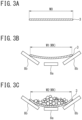
- the belt 3 in the following state depending on the tension of the belt 3. That is, in an unloading state, a belt width W1 in a top view has a length close to an actual length WO ( FIG. 3A ) of the width of the belt 3. Further, in a state where a predetermined amount of the raw material 2 is loaded on the belt 3 as illustrated in FIG. 3C , the belt 3 is in the following state. That is, in a loading state, a belt width W2 in a top view is shorter in length than the belt width W1 in a state where no raw material 2 is loaded on the belt 3.
- the belt width in a top view is referred to as an apparent width WX of the belt 3.
- a "top view” in the present specification indicates a case where the upper surface of the upper belt 3a is viewed from above and may not necessarily indicate a case where the upper belt 3a is viewed from right above.
- the conveyance state detection device 9 for the belt 3 is a device configured to determine the conveyance state of a conveyance article by the belt 3.
- the detection device 9 includes an end position detector 10, an apparent width calculator 12, a state detector 13, and a notifier 14.
- the end position detector 10 performs a process of detecting respective width-direction positions of both ends of the upper belt 3a in the width direction in a top view.
- the end position detector 10 of the present embodiment includes an imaging device and an image processor 10B.
- the imaging device includes a visible camera 10A such as a CCD camera.
- the camera 10A takes an image of the moving upper belt 3a from above.
- the camera 10A is provided to be able to take an image of the belt 3 conveying the raw material 2, from above.
- the camera 10A is provided above a given position on the belt 3 on a conveyance path of the raw material 2 from the raw material input device 20 to the chute 4, for example.
- the camera 10A takes an image of the moving belt 3. Note that one camera 10A is illustrated in FIG. 1 . Two or more cameras 10A may be disposed along the moving direction of the belt 3 (the conveyance direction of the raw material 2) .
- the camera 10A is provided such that its imaging direction is inclined toward the downstream side in the conveyance direction.
- the camera 10A can take an oblique-view image of the belt 3.
- the image processor 10B acquires captured images taken by the camera 10A at preset sampling intervals.
- the image processor 10B performs image processing on the acquired captured images.
- the image processor 10B sequentially stores the acquired captured images in a database 11.
- the image processor 10B may sequentially perform image processing on each of the captured images stored in the database 11.
- the image processor 10B performs a process of detecting the width-direction positions of both ends of the belt 3 in the width direction from a captured image taken by the camera 10A as the image processing.
- the image processor 10B of the present embodiment includes an image acquisition section 10Ba, a projective transformer 10Bb, and an end detector 10Bc.
- the image acquisition section 10Ba acquires, from the camera 10A, a captured image of the upper belt 3a which captured image is taken from above, as illustrated in FIG. 5A .
- the projective transformer 10Bb performs projective transformation on the acquired captured image to transform it to an image of the belt 3 viewed from right above.
- the projective transformer 10Bb specifies a region (a broken-line portion in FIG. 5A ) the conveyance state of which is to be detected, from the captured image.
- the projective transformer 10Bb cuts the specified region and performs projective transformation thereon.
- the resultant transformed image is illustrated in FIG. 5B .
- the specified region is set to include at least both ends of the belt 3 in the width direction.
- the present embodiment deals with a case where the camera 10A is set in a state where the axis of the camera is inclined toward the downstream side in the conveyance direction. Even in this case, in the present embodiment, an image processing region is cut appropriately and subjected to the projective transformation, so that the image can be corrected to an image in which the belt 3 is viewed from right above (in a plan view). As a result, the ends of the belt 3 can be specified accurately.
- the imaging axis of the camera 10A is set toward right below to take an image of the belt 3 from right above (in a plan view) by the camera 10A.
- the captured imaged may not necessarily be subjected to projective transformation.
- the camera 10A is provided with the imaging axis being directed toward right below, it is difficult to take all captured images with the same position and angle.
- projective transformation is performed on images, even when the images are taken with any imaging positions and angles, all the captured images can be standardized. On this account, it is preferable to perform projective transformation.
- the end detector 10Bc detects positions H of both ends of the belt 3 in the width direction in the captured image after projective transformation.
- the positions H of both ends of the belt 3 in the width direction can be specified by the following two processing methods, for example.
- a filtering process such as edge enhancement (binarization) is performed on data of the captured image to emphasize the outline of the belt 3.
- the first specifying method is a method of specifying the positions H of both ends of the belt 3 in the width direction by emphasis of the outline.
- the second specifying method is a method using a learned model (neural network) calculated by deep learning or other machine learning. That is, the second specifying method is a method of specifying the positions H of both ends of the belt 3 in the captured image by use of a learned model.
- the learned model for specifying the position of an end of the belt 3 on an image is generated.
- multiple pieces of learning data each constituted by a combination of a captured image taken in advance and information on a belt width-direction end position in the captured image, are prepared.
- the model is generated.
- Each learning data is constituted by, for example, a combination of a captured image as illustrated in FIG. 6A and an image with clearly illustrated belt width-direction end positions H1, as illustrated in FIG. 6B , within the same region as the captured image.
- the captured image of FIG. 6A is data after projective transformation.
- the image with the clearly illustrated belt width-direction end positions H1, in FIG. 6B is information on belt width-direction end positions. Note that the information on belt width-direction end positions does not need to be positions H1 themselves on a screen.
- the information on belt width-direction end positions may be values (coordinates) or the like indicative of width-direction positions in an image (in a region) in terms of the belt width-direction end positions.
- an image of learning data and an input image to a model may be captured images before projective transformation.
- Machine learning is performed using learning data acquired under various conditions.
- a learned model which receives a captured image taken by the camera 10A as input data and which provides width-direction position information on both ends of the belt 3 in the width direction as output data is generated.
- a captured image 31 (data after projective transformation) taken by the camera 10A is input into a learned model 30.
- information 32 on width-direction positions of both ends of the belt 3 in the width direction is acquired. From the acquired information 32, width-direction positions H of both ends in the width direction are specified.
- the model 30 is created by use of a plurality of pieces of learning data different in time range and weather.
- the ends of the belt 3 can be detected stably.
- a technique such as semantic segmentation may be employed.
- a learned model is generated such that teacher image data labelled per pixel is learned by convolutional neural network in terms of an edge portion and a non-edge portion in an end of the belt in the width direction.
- other well-known methods may be employed as the learning method.
- the width-direction positions of both ends of the belt 3 in the width direction are specified preferably by the second specifying method.
- the width-direction positions may be specified by a photoelectric sensor or other range finders like PTL 1 or 2.
- the apparent width calculator 12 performs processing to calculate an apparent width WX that is the width of the belt 3 in a top view, based on right and left width-direction positions of the belt 3 that are detected by the end position detector 10.
- the following assumes a case where the right and left width-direction positions of the belt 3 are acquired as edge lines in a region as illustrated in FIG. 6B .
- the apparent width WX as the width of the belt 3 in a top view is calculated by specifying the width-direction positions of the edge lines.
- the apparent width WX is calculated by addition and subtraction of the coordinate values.
- the state detector 13 includes a conveyance article state determination section 13A and a meandering state determination section 13B.
- the conveyance article state determination section 13A performs a process of determining the conveyance state of the conveyance article conveyed by the belt 3 based on the calculated apparent width WX.
- the conveyance article state determination section 13A determines the presence or absence of the raw material 2 on the belt 3, for example, based on the length of the calculated apparent width WX relative to an actual length W0 of the width of the belt 3. For example, in a case where the length of the calculated apparent width WX is less than a threshold A, the conveyance article state determination section 13A determines that the raw material 2 is loaded on the belt 3.
- the threshold A is a value set in advance as a value shorter than the actual length W0 of the width of the belt 3.
- the length of the apparent width WX of the belt 3 is relatively short in a case ( FIG. 3C ) where the raw material 2 is being conveyed in comparison with a case ( FIG. 3B ) where no raw material 2 is conveyed.
- a central portion of the belt 3 sinks and curves due to the weight of the raw material 2 during conveyance of the raw material 2. Accordingly, when the threshold A based on which the raw material 2 can be determined to be on the belt 3 is acquired in advance, it is possible to determine whether or not the raw material 2 is conveyed by the belt 3.
- the length of the apparent width WX of the belt 3 becomes shorter as the amount of loading of the raw material 2 is larger (its weight is heavier). Accordingly, when the relationship between the apparent width WX and the amount (weight) of the raw material 2 is calculated in advance, for example, it is possible to estimate the conveyance amount of the raw material 2 based on the apparent width WX of the belt 3. This also allows management (e.g., adjustment) of the conveyance amount of the raw material 2 in accordance with the estimated conveyance amount of the raw material 2.
- the length of the calculated apparent width WX relative to the actual length of the width of the belt 3 is used.
- the threshold A shorter than the actual length of the width of the belt 3 is used for the determination.
- the present invention is not limited to this.
- the ratio of the length of the calculated apparent width WX to the actual length of the width of the belt 3 may be used.
- the presence or absence of the raw material 2 on the belt 3 may be determined based on the ratio. Particularly, in a case where the conveyance amount (the amount of loading) of the raw material 2 is estimated from the apparent width WX, it is preferable to use the ratio.
- the conveyance article state determination section 13A supplies information on whether or not the raw material 2 is conveyed by the belt 3 or the conveyance amount (the amount of loading) of the raw material 2 to the notifier 14.
- the meandering state determination section 13B determines the misalignment amount of the belt 3 based on right and left width-direction positions detected by the end position detector 10.
- the meandering state determination section 13B calculates a deviation amount d of a central position Q between the right and left width-direction positions from a reference position P as illustrated in FIG. 6B .
- the reference position P is the position of a central portion of the belt 3 in the moving direction in a case where the belt 3 has no misalignment.
- the calculated deviation amount d exceeds a threshold B set in advance, it is determined that the belt 3 is largely misaligned.
- conveyance article state determination section 13A determines that the length of the apparent width WX is less than the threshold A and the belt 3 is largely misaligned, conveyance abnormality information is supplied to the notifier 14.
- the camera 10A is provided such that the center of a designated region in an image comes to the center of the belt 3 in the moving direction in a case where the belt 3 has no misalignment.
- the reference position P the central position of the facility
- the central position Q of the belt 3 in the width direction.
- the notifier 14 When the notifier 14 acquires conveyance abnormality information on the belt 3 from the meandering state determination section 13B, the notifier 14 performs a notification process of displaying the conveyance abnormality information on a screen monitored by an operator, for example. Further, the notifier 14 performs an alarm generation process or a notification process such as transmission of an E-mail. Hereby, the operator in a factory can be notified of a conveyance abnormality of the belt 3.
- the notifier 14 displays information from the conveyance article state determination section 13A on the screen monitored by the operator. Note that the conveyance information from the conveyance article state determination section 13A is not necessarily warning information.
- the raw material 2 (a conveyance article) from a captured image of the belt 3.
- the present embodiment in a case where the apparent width WX of the belt 3 is less than the threshold A, it is determined that a conveyance abnormality occurs. That is, in a case where the raw material 2 is loaded on the belt 3 and the misalignment amount of the belt 3 (the deviation amount d of the central position) exceeds the threshold B, it is determined that a conveyance abnormality occurs. In the meantime, in the present embodiment, even in a case where the misalignment amount of the belt 3 (the deviation amount d of the central position) exceeds the threshold B, when the apparent width WX of the belt 3 is equal to or more than the threshold A, it is determined that no conveyance abnormality occurs.
- the operator can be notified of only the misalignment of the belt 3 as the conveyance abnormality of the raw material 2 during conveyance.
- the operator can grasp the conveyance abnormality in the belt as distinguished from an insignificant misalignment of the belt 3 in a state where no raw material 2 is conveyed.
- the state where no raw material 2 is conveyed is an unsteady conveyer operation state before and after start or end of conveyance, for example. This makes it possible to effectively monitor belts 3 of multiple conveyers.
- it is possible to prevent a serious trouble.
- an imaging device is provided in the belt conveyor 1 to continuously monitor the belt 3.
- the captured image is processed to detect ends of the belt 3 in the width direction, for example, it is possible to efficiently detect misalignment of the belt 3 as a conveyance abnormality.
- the present embodiment it is possible to easily and accurately determine the presence or absence of a conveyance article based on a change in belt width. Accordingly, it is possible to grasp a conveyance abnormality such as the misalignment amount of the belt 3 during conveyance of the conveyance article after it is determined whether the conveyance article is conveyed or not. On this account, it is possible to take measures such as changing of process requirements or inspection or repair of the facility before a facility trouble occurs.
- the present embodiment deals with a raw material constituted by bulk material as a conveyance article, but the present invention is also applicable to a conveyance article other than the bulk material.
- This disclosure can also take the following configurations.
Landscapes
- Engineering & Computer Science (AREA)
- Physics & Mathematics (AREA)
- Computer Vision & Pattern Recognition (AREA)
- General Physics & Mathematics (AREA)
- Theoretical Computer Science (AREA)
- Mechanical Engineering (AREA)
- Geometry (AREA)
- Quality & Reliability (AREA)
- Control Of Conveyors (AREA)
- Structure Of Belt Conveyors (AREA)
Abstract
Description
- The present invention relates to a technology to detect a conveyance abnormality of a belt of a belt conveyor by determining the conveyance state of a conveyance article conveyed by the belt.
- Iron ores or coal as a main material, limestone as an auxiliary material, and the like which are necessary for an iron manufacture process are stored in a raw-material yard. The iron ores and the like are supplied to a subsequent step in a sinter plant, a cokes factory, a blast furnace, or the like as needed. In the raw-material yard, raw materials of different types or different brands are conveyed by multiple belt conveyors.
- A belt conveyor conveys a raw material by rotating an endless belt. However, the belt conveyor may have a conveyance abnormality in the belt due to an uneven loading state of the raw material, poor alignment of a pulley suspending the belt, or the like.
- When the belt has a conveyance abnormality, the raw material might fall from the belt during the conveyance so that the raw material might accumulate in an unexpected place. Further, when the belt has a conveyance abnormality, the belt might be worn out or damaged. This might cause a serious trouble leading to a facility stop.
- In order to stably operate a belt conveyor facility, it is necessary to monitor the belt appropriately while the belt is conveying a conveyance article. The monitoring is performed by detecting the conveyance state of the belt, for example.
- As a method for monitoring a belt of a belt conveyor, methods described in PTLS 1 to 3 have been proposed, for example.
- In PTL 1, deviation of a belt in its width direction is detected by a limit switch. PTL 1 discloses that the occurrence of a conveyance abnormality related to meandering of the belt is monitored.
-
PTL 2 discloses that meandering of a belt is detected by detecting an edge position of the belt by a transmissive photoelectric sensor. - Further,
PTL 3 discloses that the amount of meandering is determined consecutively based on a deviation between the center of a belt in its width direction in a captured image of the belt and the center of a line in the width direction. -
- PTL 1:
JP 2012-6703 A - PTL 2:
JP 2021-162515 A - PTL 3:
JP 2018-115054 A - The methods described in PTLS are intended to detect meandering. Accordingly, the methods described in PTLS cannot detect a conveyance abnormality such as falling of a raw material from a belt during conveyance. In addition, the methods described in PTLS cannot detect a conveyance abnormality of a belt due to poor transfer of a raw material to the belt, or the like. More specifically, the methods described in PTLS 1 to 3 might not be able to grasp the presence or absence of a conveyance article on the belt.
- Further, in a powder dust environment such as the raw-material yard, there is such a possibility that powder dust accumulates markedly in a light projection section or a light receiving section of a photoelectric sensor. On this account, in the method described in PTL 1 or
PTL 2, false detection might increase in the powder dust environment. - Further, in the method described in
PTL 3, it is necessary to visually observe a captured image via a monitor to grasp the presence or absence of a conveyance article. On this account, in the method described inPTL 3, conveyance abnormalities of multiple conveyers cannot be automatically monitored effectively. - The present invention is accomplished in view of the above problems, and an object of the present invention is to easily and accurately determine the conveyance state of a conveyance article conveyed by a belt.
- In order to achieve the object, one aspect of the present invention relates to a belt conveyance state detection device for detecting a conveyance state of a belt of a belt conveyor configured to convey a conveyance article. The belt conveyance state detection device includes: an end position detector configured to detect respective width-direction positions of both ends of the belt in a width direction in a top view; an apparent width calculator configured to calculate an apparent width as a width of the belt in the top view, based on the width-direction positions detected by the end position detector; and a state detector configured to determine a conveyance state of the conveyance article conveyed by the belt, based on the calculated apparent width.
- Further, an aspect of the present invention relates to a belt conveyance state detection method for detecting a conveyance state of a belt of a belt conveyor configured to convey a conveyance article. The belt conveyance state detection method includes determining a conveyance state of a conveyance article conveyed by the belt, based on a length of an apparent width as a width of the belt viewed in a top view relative to an actual length of the width of the belt.
- With the aspects of the present invention, it is possible to easily and accurately determine the conveyance state of the conveyance article conveyed by the belt, based on the change in the apparent width of the belt. The conveyance state of the conveyance article conveyed by the belt varies depending on the presence or absence of the conveyance article on the belt, or the like.
- As a result, with the aspects of the present invention, it is possible to take measures such as changing of an operation condition or inspection or repair of a facility before a large facility trouble occurs.
-
-
FIG. 1 is a diagrammatic view illustrating an exemplary configuration of a belt misalignment detection device according to an embodiment of the present invention; -
FIG. 2 is a sectional view illustrating the relationship between a belt and a roller; -
FIGS. 3A to 3C are views to describe the apparent width of the belt,FIG. 3A being a sectional view illustrating an actual length,FIG. 3B being a belt sectional view in a state where no raw material is put on the belt,FIG. 3C being a belt sectional view in a state where a raw material is put on the belt; -
FIG. 4 is a view illustrating the configuration of a detection device according to an embodiment based on the present invention; -
FIG. 5A is a view illustrating an example of a captured image, andFIG. 5B is a view illustrating an image after projective transformation; -
FIG. 6 is a view illustrating an example of learning data; and -
FIG. 7 is a schematic view illustrating a learning model example. - The following will describe an embodiment of the present invention with reference to the drawings.
- The present embodiment relates to a technology about a belt conveyor for conveying a raw material (a conveyance article) such as iron ores or coal in an iron manufacture process. The present embodiment deals with a case where a belt of a belt conveyor is monitored by detecting the conveyance state of the belt, as an example. The present invention is applicable to a configuration in which a raw material or other conveyance articles are conveyed by a belt conveyor. The present invention is a technology that is suitable particularly for a case where the environment in which a movable belt is disposed changes. The case where the environment changes indicate, for example, a case where at least part of the belt is disposed outdoors. The present invention is useful for monitoring of an abnormality in the conveyance state of a belt in a belt conveyor facility for conveying a raw material as particulate matter of iron ores, coal, or the like.
-
FIG. 1 is a diagrammatic view illustrating the configuration of a belt conveyor 1 and an exemplary configuration of a conveyancestate detection device 9 for abelt 3 according to the present embodiment. - The belt conveyor 1 includes an
endless belt 3 and apulley 7. Thebelt 3 moves over a plurality ofrollers 8 with a predetermined tension in response to the rotation of thepulley 7 constituted by adrive pulley 7a and a plurality of drivenpulleys 7b. Thedrive pulley 7a is rotationally driven by an electric machine 5 via aspeed reducer 6. - In the present embodiment, a roller supporting an
upper belt 3a among therollers 8 consists of a combination of acentral roller 8a and right and leftrollers 8b, as illustrated inFIG. 2 . Thecentral roller 8a is disposed in a width-direction center in a belt width direction (the right-left direction inFIG. 2 ). The right and leftrollers 8b are disposed on the right side and the left side of thecentral roller 8a such that the axes of the rollers are inclined. Hereby, the rollers supporting theupper belt 3a can support theupper belt 3a in a trapezoidal shape. Note that therollers 8 supporting alower belt 3b side are each constituted by one roller. Note that the support configuration for thebelt 3 by therollers 8 is not limited to this. - Further, in the present embodiment, a raw
material input device 20 is disposed on the upstream side from theupper belt 3a in a conveyance direction. Araw material 2 as a conveyance article is loaded on thebelt 3 from the rawmaterial input device 20. Theraw material 2 thus transferred is conveyed by theupper belt 3a. Then, theraw material 2 is conveyed by theupper belt 3a to the downstream side in the conveyance direction and is sequentially put into achute 4. - Here, in a state where no
raw material 2 is loaded on thebelt 3 as illustrated inFIG. 3B , thebelt 3 is in the following state depending on the tension of thebelt 3. That is, in an unloading state, a belt width W1 in a top view has a length close to an actual length WO (FIG. 3A ) of the width of thebelt 3. Further, in a state where a predetermined amount of theraw material 2 is loaded on thebelt 3 as illustrated inFIG. 3C , thebelt 3 is in the following state. That is, in a loading state, a belt width W2 in a top view is shorter in length than the belt width W1 in a state where noraw material 2 is loaded on thebelt 3. - Here, the belt width in a top view is referred to as an apparent width WX of the
belt 3. - Further, a "top view" in the present specification indicates a case where the upper surface of the
upper belt 3a is viewed from above and may not necessarily indicate a case where theupper belt 3a is viewed from right above. - The conveyance
state detection device 9 for thebelt 3 is a device configured to determine the conveyance state of a conveyance article by thebelt 3. - As illustrated in
FIG. 1 , thedetection device 9 includes anend position detector 10, anapparent width calculator 12, astate detector 13, and anotifier 14. - The
end position detector 10 performs a process of detecting respective width-direction positions of both ends of theupper belt 3a in the width direction in a top view. - The
end position detector 10 of the present embodiment includes an imaging device and animage processor 10B. - The imaging device includes a
visible camera 10A such as a CCD camera. Thecamera 10A takes an image of the movingupper belt 3a from above. - The
camera 10A is provided to be able to take an image of thebelt 3 conveying theraw material 2, from above. Thecamera 10A is provided above a given position on thebelt 3 on a conveyance path of theraw material 2 from the rawmaterial input device 20 to thechute 4, for example. Thecamera 10A takes an image of the movingbelt 3. Note that onecamera 10A is illustrated inFIG. 1 . Two ormore cameras 10A may be disposed along the moving direction of the belt 3 (the conveyance direction of the raw material 2) . - In the present embodiment, the
camera 10A is provided such that its imaging direction is inclined toward the downstream side in the conveyance direction. Hereby, thecamera 10A can take an oblique-view image of thebelt 3. - The
image processor 10B acquires captured images taken by thecamera 10A at preset sampling intervals. Theimage processor 10B performs image processing on the acquired captured images. Theimage processor 10B sequentially stores the acquired captured images in adatabase 11. Theimage processor 10B may sequentially perform image processing on each of the captured images stored in thedatabase 11. - The
image processor 10B performs a process of detecting the width-direction positions of both ends of thebelt 3 in the width direction from a captured image taken by thecamera 10A as the image processing. - As illustrated in
FIG. 4 , theimage processor 10B of the present embodiment includes an image acquisition section 10Ba, a projective transformer 10Bb, and an end detector 10Bc. - The image acquisition section 10Ba acquires, from the
camera 10A, a captured image of theupper belt 3a which captured image is taken from above, as illustrated inFIG. 5A . - The projective transformer 10Bb performs projective transformation on the acquired captured image to transform it to an image of the
belt 3 viewed from right above. For example, the projective transformer 10Bb specifies a region (a broken-line portion inFIG. 5A ) the conveyance state of which is to be detected, from the captured image. The projective transformer 10Bb cuts the specified region and performs projective transformation thereon. The resultant transformed image is illustrated inFIG. 5B . Note that the specified region is set to include at least both ends of thebelt 3 in the width direction. - The present embodiment deals with a case where the
camera 10A is set in a state where the axis of the camera is inclined toward the downstream side in the conveyance direction. Even in this case, in the present embodiment, an image processing region is cut appropriately and subjected to the projective transformation, so that the image can be corrected to an image in which thebelt 3 is viewed from right above (in a plan view). As a result, the ends of thebelt 3 can be specified accurately. - Here assume a case where the imaging axis of the
camera 10A is set toward right below to take an image of thebelt 3 from right above (in a plan view) by thecamera 10A. In this case, the captured imaged may not necessarily be subjected to projective transformation. However, even in a case where thecamera 10A is provided with the imaging axis being directed toward right below, it is difficult to take all captured images with the same position and angle. In contrast, in a case where projective transformation is performed on images, even when the images are taken with any imaging positions and angles, all the captured images can be standardized. On this account, it is preferable to perform projective transformation. - The end detector 10Bc detects positions H of both ends of the
belt 3 in the width direction in the captured image after projective transformation. - The positions H of both ends of the
belt 3 in the width direction can be specified by the following two processing methods, for example. - In a first specifying method, a filtering process such as edge enhancement (binarization) is performed on data of the captured image to emphasize the outline of the
belt 3. The first specifying method is a method of specifying the positions H of both ends of thebelt 3 in the width direction by emphasis of the outline. - The second specifying method is a method using a learned model (neural network) calculated by deep learning or other machine learning. That is, the second specifying method is a method of specifying the positions H of both ends of the
belt 3 in the captured image by use of a learned model. - In this case, the learned model for specifying the position of an end of the
belt 3 on an image is generated. At the time of generating the learned model, multiple pieces of learning data, each constituted by a combination of a captured image taken in advance and information on a belt width-direction end position in the captured image, are prepared. When machine learning is performed by use of the multiple pieces of learning data in advance, the model is generated. - Each learning data is constituted by, for example, a combination of a captured image as illustrated in
FIG. 6A and an image with clearly illustrated belt width-direction end positions H1, as illustrated inFIG. 6B , within the same region as the captured image. The captured image ofFIG. 6A is data after projective transformation. The image with the clearly illustrated belt width-direction end positions H1, inFIG. 6B , is information on belt width-direction end positions. Note that the information on belt width-direction end positions does not need to be positions H1 themselves on a screen. The information on belt width-direction end positions may be values (coordinates) or the like indicative of width-direction positions in an image (in a region) in terms of the belt width-direction end positions. - Note that an image of learning data and an input image to a model may be captured images before projective transformation.
- Machine learning is performed using learning data acquired under various conditions. A learned model which receives a captured image taken by the
camera 10A as input data and which provides width-direction position information on both ends of thebelt 3 in the width direction as output data is generated. - In the second specifying method, as illustrated in
FIG. 7 , a captured image 31 (data after projective transformation) taken by thecamera 10A is input into a learnedmodel 30. Hereby,information 32 on width-direction positions of both ends of thebelt 3 in the width direction is acquired. From the acquiredinformation 32, width-direction positions H of both ends in the width direction are specified. - In the second specifying method, the
model 30 is created by use of a plurality of pieces of learning data different in time range and weather. Hereby, even in a captured image of the belt conveyor 1 provided outdoors such as a raw-material yard, the ends of thebelt 3 can be detected stably. - As the machine learning, a technique such as semantic segmentation may be employed. In this case, for example, a learned model is generated such that teacher image data labelled per pixel is learned by convolutional neural network in terms of an edge portion and a non-edge portion in an end of the belt in the width direction. Further, other well-known methods may be employed as the learning method.
- Here, the width-direction positions of both ends of the
belt 3 in the width direction are specified preferably by the second specifying method. The width-direction positions may be specified by a photoelectric sensor or other range finders likePTL 1 or 2. - The
apparent width calculator 12 performs processing to calculate an apparent width WX that is the width of thebelt 3 in a top view, based on right and left width-direction positions of thebelt 3 that are detected by theend position detector 10. - The following assumes a case where the right and left width-direction positions of the
belt 3 are acquired as edge lines in a region as illustrated inFIG. 6B . In this case, the apparent width WX as the width of thebelt 3 in a top view is calculated by specifying the width-direction positions of the edge lines. - Further, in a case where the right and left width-direction positions of the
belt 3 are acquired in the form of coordinate values, the apparent width WX is calculated by addition and subtraction of the coordinate values. - As illustrated in
FIG. 4 , thestate detector 13 includes a conveyance articlestate determination section 13A and a meanderingstate determination section 13B. - The conveyance article
state determination section 13A performs a process of determining the conveyance state of the conveyance article conveyed by thebelt 3 based on the calculated apparent width WX. - The conveyance article
state determination section 13A determines the presence or absence of theraw material 2 on thebelt 3, for example, based on the length of the calculated apparent width WX relative to an actual length W0 of the width of thebelt 3. For example, in a case where the length of the calculated apparent width WX is less than a threshold A, the conveyance articlestate determination section 13A determines that theraw material 2 is loaded on thebelt 3. The threshold A is a value set in advance as a value shorter than the actual length W0 of the width of thebelt 3. - Here, as described above (see
FIG. 3 ), the length of the apparent width WX of thebelt 3 is relatively short in a case (FIG. 3C ) where theraw material 2 is being conveyed in comparison with a case (FIG. 3B ) where noraw material 2 is conveyed. This is because a central portion of thebelt 3 sinks and curves due to the weight of theraw material 2 during conveyance of theraw material 2. Accordingly, when the threshold A based on which theraw material 2 can be determined to be on thebelt 3 is acquired in advance, it is possible to determine whether or not theraw material 2 is conveyed by thebelt 3. - Further, the length of the apparent width WX of the
belt 3 becomes shorter as the amount of loading of theraw material 2 is larger (its weight is heavier). Accordingly, when the relationship between the apparent width WX and the amount (weight) of theraw material 2 is calculated in advance, for example, it is possible to estimate the conveyance amount of theraw material 2 based on the apparent width WX of thebelt 3. This also allows management (e.g., adjustment) of the conveyance amount of theraw material 2 in accordance with the estimated conveyance amount of theraw material 2. - Here, in the above description, the length of the calculated apparent width WX relative to the actual length of the width of the
belt 3 is used. Further, the threshold A shorter than the actual length of the width of thebelt 3 is used for the determination. However, the present invention is not limited to this. For example, the ratio of the length of the calculated apparent width WX to the actual length of the width of thebelt 3 may be used. The presence or absence of theraw material 2 on thebelt 3 may be determined based on the ratio. Particularly, in a case where the conveyance amount (the amount of loading) of theraw material 2 is estimated from the apparent width WX, it is preferable to use the ratio. - The conveyance article
state determination section 13A supplies information on whether or not theraw material 2 is conveyed by thebelt 3 or the conveyance amount (the amount of loading) of theraw material 2 to thenotifier 14. - The meandering
state determination section 13B determines the misalignment amount of thebelt 3 based on right and left width-direction positions detected by theend position detector 10. - For example, the meandering
state determination section 13B calculates a deviation amount d of a central position Q between the right and left width-direction positions from a reference position P as illustrated inFIG. 6B . The reference position P is the position of a central portion of thebelt 3 in the moving direction in a case where thebelt 3 has no misalignment. In a case where the calculated deviation amount d exceeds a threshold B set in advance, it is determined that thebelt 3 is largely misaligned. In the present embodiment, when the conveyance articlestate determination section 13A determines that the length of the apparent width WX is less than the threshold A and thebelt 3 is largely misaligned, conveyance abnormality information is supplied to thenotifier 14. - Here assume a case where the
camera 10A is provided such that the center of a designated region in an image comes to the center of thebelt 3 in the moving direction in a case where thebelt 3 has no misalignment. In this case, the reference position P (the central position of the facility) of a region ofFIG. 6 overlaps with the central position Q of thebelt 3 in the width direction. - When the
notifier 14 acquires conveyance abnormality information on thebelt 3 from the meanderingstate determination section 13B, thenotifier 14 performs a notification process of displaying the conveyance abnormality information on a screen monitored by an operator, for example. Further, thenotifier 14 performs an alarm generation process or a notification process such as transmission of an E-mail. Hereby, the operator in a factory can be notified of a conveyance abnormality of thebelt 3. - Further, the
notifier 14 displays information from the conveyance articlestate determination section 13A on the screen monitored by the operator. Note that the conveyance information from the conveyance articlestate determination section 13A is not necessarily warning information. - Generally, it is difficult to directly detect the raw material 2 (a conveyance article) from a captured image of the
belt 3. However, in the present embodiment, it is possible to easily determine whether theraw material 2 is conveyed or not, based on the apparent width WX of thebelt 3. This makes it possible to easily and accurately determine the presence or absence of theraw material 2. Hereby, it is possible to detect a conveyance abnormality state in which noraw material 2 is loaded even though theraw material 2 should be conveyed. Note that notification about whether or not theraw material 2 is conveyed may not be notified. - Further, in the present embodiment, in a case where the apparent width WX of the
belt 3 is less than the threshold A, it is determined that a conveyance abnormality occurs. That is, in a case where theraw material 2 is loaded on thebelt 3 and the misalignment amount of the belt 3 (the deviation amount d of the central position) exceeds the threshold B, it is determined that a conveyance abnormality occurs. In the meantime, in the present embodiment, even in a case where the misalignment amount of the belt 3 (the deviation amount d of the central position) exceeds the threshold B, when the apparent width WX of thebelt 3 is equal to or more than the threshold A, it is determined that no conveyance abnormality occurs. That is, in a case where noraw material 2 is on thebelt 3, it is determined that no conveyance abnormality occurs. As such, in the present embodiment, it is determined whether or not the misalignment amount of thebelt 3 is abnormal based on the determination on whether or not theraw material 2 is conveyed. - Accordingly, in the present embodiment, the operator can be notified of only the misalignment of the
belt 3 as the conveyance abnormality of theraw material 2 during conveyance. The operator can grasp the conveyance abnormality in the belt as distinguished from an insignificant misalignment of thebelt 3 in a state where noraw material 2 is conveyed. The state where noraw material 2 is conveyed is an unsteady conveyer operation state before and after start or end of conveyance, for example. This makes it possible to effectively monitorbelts 3 of multiple conveyers. As a result, in the present embodiment, it is possible to change process requirements to prevent misalignment of thebelt 3 or to take corrective measures to a conveyance abnormality by checking the facility at an early stage. Thus, in the present embodiment, it is possible to prevent a serious trouble. - As described above, in the present embodiment, an imaging device is provided in the belt conveyor 1 to continuously monitor the
belt 3. When the captured image is processed to detect ends of thebelt 3 in the width direction, for example, it is possible to efficiently detect misalignment of thebelt 3 as a conveyance abnormality. As a result, in the present embodiment, it is possible to take effective measures before a serious facility trouble occurs. Further, it is possible to prevent a production loss or a facility failure. - Further, in the present embodiment, it is possible to easily and accurately determine the presence or absence of a conveyance article based on a change in belt width. Accordingly, it is possible to grasp a conveyance abnormality such as the misalignment amount of the
belt 3 during conveyance of the conveyance article after it is determined whether the conveyance article is conveyed or not. On this account, it is possible to take measures such as changing of process requirements or inspection or repair of the facility before a facility trouble occurs. - Here, the present embodiment deals with a raw material constituted by bulk material as a conveyance article, but the present invention is also applicable to a conveyance article other than the bulk material.
- This disclosure can also take the following configurations.
- (1) A belt conveyance state detection device for detecting a conveyance state of a belt of a belt conveyor configured to convey a conveyance article includes: an end position detector configured to detect respective width-direction positions of both ends of the belt in a width direction in a top view; an apparent width calculator configured to calculate an apparent width as a width of the belt in the top view, based on the width-direction positions detected by the end position detector; and a state detector configured to determine a conveyance state of the conveyance article conveyed by the belt, based on the calculated apparent width.
- (2) The state detector determines at least presence or absence of the conveyance article on the belt out of the presence or absence of the conveyance article and a loading amount of the conveyance article, based on a length of the calculated apparent width relative to an actual length of a width of the belt.
- (3) In a case where the length of the apparent width thus calculated is less than a threshold set in advance as a value shorter than the actual length of the width of the belt, the state detector determines that the conveyance article is on the belt.
- (4) The state detector further determines a misalignment amount of the belt, based on the detected width-direction positions of both ends of the belt in the width direction.
- (5) The belt conveyance state detection device further includes a notifier configured to notify conveyance abnormality information on the belt in a case where the state detector determines that the conveyance article is on the belt and the belt is largely misaligned.
- (6) The end position detector includes: an imaging device configured to take a captured image of the belt from above; and an image processor configured to detect respective width-direction positions of both ends of the belt in the width direction from the captured image taken by the imaging device.
- (7) The image processor detects the respective width-direction positions of both ends of the belt in the width direction from the captured image after projective transformation.
- (8) The image processor detects the respective width-direction positions of both ends of the belt in the width direction from the captured image taken by the imaging device, by use of a learned model configured to specify belt end positions on an image, the learned model being a model obtained by machine learning by use of a learning data constituted by a combination of a captured image taken in advance and information on belt width-direction end positions in the captured image.
- (9) A belt conveyance state detection method for detecting a conveyance state of a belt of a belt conveyor configured to convey a conveyance article includes determining a conveyance state of a conveyance article conveyed by the belt, based on a length of an apparent width as a width of the belt viewed in a top view relative to an actual length of the width of the belt.
- Here,
Japanese Patent Application No. 2022-034560 (filed on March 7, 2022 -
- 1
- belt conveyor
- 2
- raw material (conveyance article)
- 3
- belt
- 3a
- upper belt
- 3b
- lower belt
- 7
- pulley
- 8
- roller
- 8a
- central roller
- 8b
- right and left rollers
- 9
- conveyance state detection device
- 10
- end position detector
- 10A
- camera
- 10B
- image processor
- 10Ba
- image acquisition section
- 10Bb
- projective transformer
- 10Bc
- end detector
- 12
- apparent width calculator
- 13
- state detector
- 13A
- conveyance article state determination section
- 13B
- meandering state determination section
- 14
- notifier
- 30
- learned model
- 31
- captured image
- 32
- information on width-direction position of belt width-direction end
- A
- threshold
- B
- threshold
- H
- width-direction position
- P
- reference position
- Q
- central position of belt
- WO
- actual length
- WX
- apparent width
- d
- misalignment amount
Claims (9)
- A belt conveyance state detection device for detecting a conveyance state of a belt of a belt conveyor configured to convey a conveyance article, the belt conveyance state detection device comprising:an end position detector configured to detect respective width-direction positions of both ends of the belt in a width direction in a top view;an apparent width calculator configured to calculate an apparent width as a width of the belt in the top view, based on the width-direction positions detected by the end position detector; anda state detector configured to determine a conveyance state of the conveyance article conveyed by the belt, based on the calculated apparent width.
- The belt conveyance state detection device according to claim 1, wherein
the state detector determines at least presence or absence of the conveyance article on the belt out of the presence or absence of the conveyance article and a loading amount of the conveyance article, based on a length of the calculated apparent width relative to an actual length of a width of the belt. - The belt conveyance state detection device according to claim 2, wherein
in a case where the length of the apparent width thus calculated is less than a threshold set in advance as a value shorter than the actual length of the width of the belt, the state detector determines that the conveyance article is on the belt. - The belt conveyance state detection device according to claim 2 or 3, wherein
the state detector further determines a misalignment amount of the belt, based on the detected width-direction positions of both ends of the belt in the width direction. - The belt conveyance state detection device according to claim 4, further comprising:
a notifier configured to notify conveyance abnormality information of the belt in a case where the state detector determines that the conveyance article is on the belt and the belt is largely misaligned. - The belt conveyance state detection device according to any one of claims 1 to 5, wherein
the end position detector includesan imaging device configured to take a captured image of the belt from above; andan image processor configured to detect respective width-direction positions of both ends of the belt in the width direction from the captured image taken by the imaging device. - The belt conveyance state detection device according to claim 6, wherein
the image processor detects the respective width-direction positions of both ends of the belt in the width direction from the captured image after projective transformation. - The belt conveyance state detection device according to claim 6 or 7, wherein
the image processor detects the respective width-direction positions of both ends of the belt in the width direction from the captured image taken by the imaging device, by use of a learned model configured to specify belt end positions on an image, the learned model being a model obtained by machine learning by use of a learning data constituted by a combination of a captured image taken in advance and information on belt width-direction end positions in the captured image. - A belt conveyance state detection method for detecting a conveyance state of a belt of a belt conveyor configured to convey a conveyance article, the belt conveyance state detection method comprising:
determining a conveyance state of a conveyance article conveyed by the belt, based on a length of an apparent width as a width of the belt viewed in a top view relative to an actual length of the width of the belt.
Applications Claiming Priority (2)
| Application Number | Priority Date | Filing Date | Title |
|---|---|---|---|
| JP2022034560 | 2022-03-07 | ||
| PCT/JP2023/008372 WO2023171624A1 (en) | 2022-03-07 | 2023-03-06 | Belt conveyance state detection device and belt conveyance state detection method |
Publications (2)
| Publication Number | Publication Date |
|---|---|
| EP4461677A1 true EP4461677A1 (en) | 2024-11-13 |
| EP4461677A4 EP4461677A4 (en) | 2025-05-07 |
Family
ID=87935155
Family Applications (1)
| Application Number | Title | Priority Date | Filing Date |
|---|---|---|---|
| EP23766800.9A Pending EP4461677A4 (en) | 2022-03-07 | 2023-03-06 | Belt conveyance state detection device and belt conveyance state detection method |
Country Status (5)
| Country | Link |
|---|---|
| EP (1) | EP4461677A4 (en) |
| JP (1) | JP7473085B2 (en) |
| KR (1) | KR20240132361A (en) |
| CN (1) | CN118786083A (en) |
| WO (1) | WO2023171624A1 (en) |
Families Citing this family (1)
| Publication number | Priority date | Publication date | Assignee | Title |
|---|---|---|---|---|
| CN118907783B (en) * | 2024-08-01 | 2025-01-14 | 江苏星辉新能源科技有限公司 | Conveyor belt fault prediction system and method based on multimodal data analysis |
Family Cites Families (15)
| Publication number | Priority date | Publication date | Assignee | Title |
|---|---|---|---|---|
| JP5207820B2 (en) * | 2008-05-13 | 2013-06-12 | 株式会社Pfu | Drawing information management apparatus and verification inspection method |
| CN101738224A (en) * | 2008-11-04 | 2010-06-16 | 任安祥 | Working condition detecting method, device and system |
| JP5679707B2 (en) | 2010-06-24 | 2015-03-04 | 大成建設株式会社 | Belt conveyor monitoring system |
| JP2012046328A (en) * | 2010-08-27 | 2012-03-08 | Jfe Steel Corp | Detector for vertical-split of conveyor belt |
| JP5939051B2 (en) * | 2012-06-14 | 2016-06-22 | 横浜ゴム株式会社 | Belt conveyor equipment |
| CN105083912B (en) * | 2015-07-07 | 2017-07-11 | 青岛科技大学 | A kind of belt deflection detection method based on image recognition |
| JP6903922B2 (en) * | 2017-01-18 | 2021-07-14 | 横浜ゴム株式会社 | Conveyor belt monitoring system |
| JP6809494B2 (en) * | 2017-07-14 | 2021-01-06 | Jfeスチール株式会社 | Belt conveyor management method and management system |
| CA3086372C (en) * | 2019-07-11 | 2022-11-29 | Mark Polak | Monitoring a transverse position of a conveyor belt and its material load by digital image analysis |
| CN111204566B (en) * | 2020-01-07 | 2021-08-06 | 江苏五洋停车产业集团股份有限公司 | Belt deviation monitoring device and method based on machine vision |
| JP7413897B2 (en) | 2020-04-01 | 2024-01-16 | コニカミノルタ株式会社 | Meandering detection system |
| US12322131B2 (en) | 2020-08-18 | 2025-06-03 | Unity IPR ApS | Method and system for displaying a large 3D model on a remote device |
| CN112573138A (en) * | 2020-12-29 | 2021-03-30 | 华侨大学 | Automatic deviation rectifying and adjusting system and method for conveying device |
| CN113306991B (en) * | 2021-04-16 | 2023-07-04 | 北京伟景智能科技有限公司 | Coal conveyor monitoring management system based on stereoscopic vision |
| CN113998369B (en) * | 2021-11-05 | 2022-07-12 | 宁夏广天夏科技股份有限公司 | A coal mining speed control system and speed control method |
-
2023
- 2023-03-06 KR KR1020247026771A patent/KR20240132361A/en active Pending
- 2023-03-06 WO PCT/JP2023/008372 patent/WO2023171624A1/en not_active Ceased
- 2023-03-06 JP JP2023533596A patent/JP7473085B2/en active Active
- 2023-03-06 EP EP23766800.9A patent/EP4461677A4/en active Pending
- 2023-03-06 CN CN202380024569.9A patent/CN118786083A/en active Pending
Also Published As
| Publication number | Publication date |
|---|---|
| WO2023171624A1 (en) | 2023-09-14 |
| KR20240132361A (en) | 2024-09-03 |
| EP4461677A4 (en) | 2025-05-07 |
| JP7473085B2 (en) | 2024-04-23 |
| CN118786083A (en) | 2024-10-15 |
| JPWO2023171624A1 (en) | 2023-09-14 |
Similar Documents
| Publication | Publication Date | Title |
|---|---|---|
| JP6973529B2 (en) | Belt conveyor abnormality monitoring device, abnormality monitoring program and abnormality monitoring method | |
| CN105229698A (en) | Method for monitoring and controlling a filling system and device for carrying out the method | |
| JP6809494B2 (en) | Belt conveyor management method and management system | |
| CN211100241U (en) | A removing devices for flaw visual detection | |
| US10189649B2 (en) | Conveying system | |
| EP4464632A1 (en) | Conveyance state detection device and conveyance state detection method | |
| KR101196444B1 (en) | Total monitoring apparatus amd method of conveyor system | |
| JPH06127663A (en) | Method for measuring loading state of powder and granular lumps on belt conveyor and method for controlling meandering of conveyor | |
| JP7473085B2 (en) | Belt conveyance state detection device and belt conveyance state detection method | |
| KR100856301B1 (en) | Abnormal transport monitoring device of belt conveyor equipment | |
| CN108657771A (en) | A kind of belt conveyor material monitoring device | |
| JP7416123B2 (en) | Sediment detection device and sediment detection method | |
| JP2007230706A (en) | Belt conveyor longitudinal tear detection method and apparatus | |
| JP6439940B2 (en) | Device for preventing deviation of conveyor belt in belt conveyor and method for preventing deviation of conveyor belt using the device | |
| JP4438991B2 (en) | X-ray inspection equipment | |
| JP3974015B2 (en) | Item inspection system | |
| JP2024103217A (en) | Belt conveyor equipment abnormality detection system and abnormality detection method | |
| JP6206318B2 (en) | Conveyor transported object monitoring method and monitoring apparatus | |
| JP2004279059A (en) | Radiation inspection equipment | |
| JP7483267B2 (en) | Rolling monitoring system for pipe conveyors | |
| KR101294916B1 (en) | Materials treatment apparatus | |
| US20230339693A1 (en) | A method and system for identifying anomalies during operation of a conveyor system, in particular of an airport luggage carousel | |
| CN119734973B (en) | A conveyor belt misalignment detection system | |
| KR100758423B1 (en) | Shipment recovery device of belt conveyor | |
| CN114120182A (en) | Non-contact belt deviation detection system |
Legal Events
| Date | Code | Title | Description |
|---|---|---|---|
| STAA | Information on the status of an ep patent application or granted ep patent |
Free format text: STATUS: THE INTERNATIONAL PUBLICATION HAS BEEN MADE |
|
| PUAI | Public reference made under article 153(3) epc to a published international application that has entered the european phase |
Free format text: ORIGINAL CODE: 0009012 |
|
| STAA | Information on the status of an ep patent application or granted ep patent |
Free format text: STATUS: REQUEST FOR EXAMINATION WAS MADE |
|
| 17P | Request for examination filed |
Effective date: 20240807 |
|
| AK | Designated contracting states |
Kind code of ref document: A1 Designated state(s): AL AT BE BG CH CY CZ DE DK EE ES FI FR GB GR HR HU IE IS IT LI LT LU LV MC ME MK MT NL NO PL PT RO RS SE SI SK SM TR |
|
| A4 | Supplementary search report drawn up and despatched |
Effective date: 20250408 |
|
| RIC1 | Information provided on ipc code assigned before grant |
Ipc: G06T 7/00 20170101ALI20250403BHEP Ipc: B65G 43/02 20060101ALI20250403BHEP Ipc: B65G 15/08 20060101ALI20250403BHEP Ipc: B65G 43/08 20060101AFI20250403BHEP |
|
| DAV | Request for validation of the european patent (deleted) | ||
| DAX | Request for extension of the european patent (deleted) |