EP4461432A1 - Method for manufacturing fin - Google Patents
Method for manufacturing fin Download PDFInfo
- Publication number
- EP4461432A1 EP4461432A1 EP23778788.2A EP23778788A EP4461432A1 EP 4461432 A1 EP4461432 A1 EP 4461432A1 EP 23778788 A EP23778788 A EP 23778788A EP 4461432 A1 EP4461432 A1 EP 4461432A1
- Authority
- EP
- European Patent Office
- Prior art keywords
- fin
- axis direction
- slit
- continuous
- plate
- Prior art date
- Legal status (The legal status is an assumption and is not a legal conclusion. Google has not performed a legal analysis and makes no representation as to the accuracy of the status listed.)
- Pending
Links
Images




Classifications
-
- F—MECHANICAL ENGINEERING; LIGHTING; HEATING; WEAPONS; BLASTING
- F28—HEAT EXCHANGE IN GENERAL
- F28F—DETAILS OF HEAT-EXCHANGE AND HEAT-TRANSFER APPARATUS, OF GENERAL APPLICATION
- F28F1/00—Tubular elements; Assemblies of tubular elements
- F28F1/10—Tubular elements and assemblies thereof with means for increasing heat-transfer area, e.g. with fins, with projections, with recesses
- F28F1/12—Tubular elements and assemblies thereof with means for increasing heat-transfer area, e.g. with fins, with projections, with recesses the means being only outside the tubular element
- F28F1/24—Tubular elements and assemblies thereof with means for increasing heat-transfer area, e.g. with fins, with projections, with recesses the means being only outside the tubular element and extending transversely
- F28F1/32—Tubular elements and assemblies thereof with means for increasing heat-transfer area, e.g. with fins, with projections, with recesses the means being only outside the tubular element and extending transversely the means having portions engaging further tubular elements
- F28F1/325—Fins with openings
-
- F—MECHANICAL ENGINEERING; LIGHTING; HEATING; WEAPONS; BLASTING
- F28—HEAT EXCHANGE IN GENERAL
- F28F—DETAILS OF HEAT-EXCHANGE AND HEAT-TRANSFER APPARATUS, OF GENERAL APPLICATION
- F28F3/00—Plate-like or laminated elements; Assemblies of plate-like or laminated elements
- F28F3/02—Elements or assemblies thereof with means for increasing heat-transfer area, e.g. with fins, with recesses, with corrugations
- F28F3/025—Elements or assemblies thereof with means for increasing heat-transfer area, e.g. with fins, with recesses, with corrugations the means being corrugated, plate-like elements
- F28F3/027—Elements or assemblies thereof with means for increasing heat-transfer area, e.g. with fins, with recesses, with corrugations the means being corrugated, plate-like elements with openings, e.g. louvered corrugated fins; Assemblies of corrugated strips
-
- B—PERFORMING OPERATIONS; TRANSPORTING
- B21—MECHANICAL METAL-WORKING WITHOUT ESSENTIALLY REMOVING MATERIAL; PUNCHING METAL
- B21D—WORKING OR PROCESSING OF SHEET METAL OR METAL TUBES, RODS OR PROFILES WITHOUT ESSENTIALLY REMOVING MATERIAL; PUNCHING METAL
- B21D19/00—Flanging or other edge treatment, e.g. of tubes
- B21D19/08—Flanging or other edge treatment, e.g. of tubes by single or successive action of pressing tools, e.g. vice jaws
-
- B—PERFORMING OPERATIONS; TRANSPORTING
- B21—MECHANICAL METAL-WORKING WITHOUT ESSENTIALLY REMOVING MATERIAL; PUNCHING METAL
- B21D—WORKING OR PROCESSING OF SHEET METAL OR METAL TUBES, RODS OR PROFILES WITHOUT ESSENTIALLY REMOVING MATERIAL; PUNCHING METAL
- B21D22/00—Shaping without cutting, by stamping, spinning, or deep-drawing
- B21D22/02—Stamping using rigid devices or tools
-
- B—PERFORMING OPERATIONS; TRANSPORTING
- B21—MECHANICAL METAL-WORKING WITHOUT ESSENTIALLY REMOVING MATERIAL; PUNCHING METAL
- B21D—WORKING OR PROCESSING OF SHEET METAL OR METAL TUBES, RODS OR PROFILES WITHOUT ESSENTIALLY REMOVING MATERIAL; PUNCHING METAL
- B21D22/00—Shaping without cutting, by stamping, spinning, or deep-drawing
- B21D22/20—Deep-drawing
-
- B—PERFORMING OPERATIONS; TRANSPORTING
- B21—MECHANICAL METAL-WORKING WITHOUT ESSENTIALLY REMOVING MATERIAL; PUNCHING METAL
- B21D—WORKING OR PROCESSING OF SHEET METAL OR METAL TUBES, RODS OR PROFILES WITHOUT ESSENTIALLY REMOVING MATERIAL; PUNCHING METAL
- B21D28/00—Shaping by press-cutting; Perforating
- B21D28/02—Punching blanks or articles with or without obtaining scrap; Notching
- B21D28/10—Incompletely punching in such a manner that the parts are still coherent with the work
-
- B—PERFORMING OPERATIONS; TRANSPORTING
- B21—MECHANICAL METAL-WORKING WITHOUT ESSENTIALLY REMOVING MATERIAL; PUNCHING METAL
- B21D—WORKING OR PROCESSING OF SHEET METAL OR METAL TUBES, RODS OR PROFILES WITHOUT ESSENTIALLY REMOVING MATERIAL; PUNCHING METAL
- B21D28/00—Shaping by press-cutting; Perforating
- B21D28/24—Perforating, i.e. punching holes
- B21D28/26—Perforating, i.e. punching holes in sheets or flat parts
-
- B—PERFORMING OPERATIONS; TRANSPORTING
- B21—MECHANICAL METAL-WORKING WITHOUT ESSENTIALLY REMOVING MATERIAL; PUNCHING METAL
- B21D—WORKING OR PROCESSING OF SHEET METAL OR METAL TUBES, RODS OR PROFILES WITHOUT ESSENTIALLY REMOVING MATERIAL; PUNCHING METAL
- B21D31/00—Other methods for working sheet metal, metal tubes, metal profiles
- B21D31/06—Deforming sheet metal, tubes or profiles by sequential impacts, e.g. hammering, beating, peen forming
-
- B—PERFORMING OPERATIONS; TRANSPORTING
- B21—MECHANICAL METAL-WORKING WITHOUT ESSENTIALLY REMOVING MATERIAL; PUNCHING METAL
- B21D—WORKING OR PROCESSING OF SHEET METAL OR METAL TUBES, RODS OR PROFILES WITHOUT ESSENTIALLY REMOVING MATERIAL; PUNCHING METAL
- B21D53/00—Making other particular articles
- B21D53/02—Making other particular articles heat exchangers or parts thereof, e.g. radiators, condensers fins, headers
- B21D53/022—Making the fins
-
- F—MECHANICAL ENGINEERING; LIGHTING; HEATING; WEAPONS; BLASTING
- F28—HEAT EXCHANGE IN GENERAL
- F28D—HEAT-EXCHANGE APPARATUS, NOT PROVIDED FOR IN ANOTHER SUBCLASS, IN WHICH THE HEAT-EXCHANGE MEDIA DO NOT COME INTO DIRECT CONTACT
- F28D1/00—Heat-exchange apparatus having stationary conduit assemblies for one heat-exchange medium only, the media being in contact with different sides of the conduit wall, in which the other heat-exchange medium is a large body of fluid, e.g. domestic or motor car radiators
- F28D1/02—Heat-exchange apparatus having stationary conduit assemblies for one heat-exchange medium only, the media being in contact with different sides of the conduit wall, in which the other heat-exchange medium is a large body of fluid, e.g. domestic or motor car radiators with heat-exchange conduits immersed in the body of fluid
- F28D1/04—Heat-exchange apparatus having stationary conduit assemblies for one heat-exchange medium only, the media being in contact with different sides of the conduit wall, in which the other heat-exchange medium is a large body of fluid, e.g. domestic or motor car radiators with heat-exchange conduits immersed in the body of fluid with tubular conduits
- F28D1/053—Heat-exchange apparatus having stationary conduit assemblies for one heat-exchange medium only, the media being in contact with different sides of the conduit wall, in which the other heat-exchange medium is a large body of fluid, e.g. domestic or motor car radiators with heat-exchange conduits immersed in the body of fluid with tubular conduits the conduits being straight
- F28D1/0535—Heat-exchange apparatus having stationary conduit assemblies for one heat-exchange medium only, the media being in contact with different sides of the conduit wall, in which the other heat-exchange medium is a large body of fluid, e.g. domestic or motor car radiators with heat-exchange conduits immersed in the body of fluid with tubular conduits the conduits being straight the conduits having a non-circular cross-section
- F28D1/05366—Assemblies of conduits connected to common headers, e.g. core type radiators
-
- F—MECHANICAL ENGINEERING; LIGHTING; HEATING; WEAPONS; BLASTING
- F28—HEAT EXCHANGE IN GENERAL
- F28F—DETAILS OF HEAT-EXCHANGE AND HEAT-TRANSFER APPARATUS, OF GENERAL APPLICATION
- F28F2215/00—Fins
- F28F2215/08—Fins with openings, e.g. louvers
-
- F—MECHANICAL ENGINEERING; LIGHTING; HEATING; WEAPONS; BLASTING
- F28—HEAT EXCHANGE IN GENERAL
- F28F—DETAILS OF HEAT-EXCHANGE AND HEAT-TRANSFER APPARATUS, OF GENERAL APPLICATION
- F28F2255/00—Heat exchanger elements made of materials having special features or resulting from particular manufacturing processes
- F28F2255/08—Heat exchanger elements made of materials having special features or resulting from particular manufacturing processes pressed; stamped; deep-drawn
Definitions
- the present disclosure relates to a method for manufacturing a fin.
- Patent Document 1 discloses a mold apparatus for manufacturing a fin.
- the mold apparatus described in Patent Document 1 manufactures the fin by pressing a thin metal plate.
- pressure is applied to the thin metal plate by press working.
- the pressure is applied unevenly to part of the thin metal plate, and the fin may be warped.
- Patent Document 1 Japanese Patent No. 2695126
- An object of the present disclosure is to reduce warp of the fin.
- a first aspect is directed to a method for manufacturing a fin.
- the method for manufacturing the fin is a method for processing a plate-shaped fin material (A) into a fin (1) for a heat exchanger.
- the method for manufacturing the fin includes: a waffle forming step of forming a waffle portion and a plate-shaped portion (11) around the waffle portion in the fin material (A); a cutting step of forming a continuous portion (12) continuous with the plate-shaped portion (11) and a fin slit (13) for receiving a flat tube in a side of the plate-shaped portion (11) of the fin material (A); and a drawing step of forming a drawn portion (18) protruding with respect to the continuous portion (12) in the continuous portion (12).
- warp of the fin (1) can be reduced.
- a second aspect is an embodiment of the first aspect.
- the method further includes a hitting step of hitting the continuous portion (12).
- the length of the fin (1) can be corrected so that the fin (1) is not excessively shorter than a predetermined target length.
- a third aspect is an embodiment of the second aspect.
- the continuous portion (12) is hit from a side toward which the drawn portion (18) protrudes.
- the continuous portion (12) of the fin (1) can be hit from the side toward which the drawn portion (18) protrudes.
- a fourth aspect is an embodiment of any one of the first to third aspects.
- the method further includes a flanging step of forming a flange (17) at an edge of the fin slit (13).
- the flange (17) maintains the strength of the fin (1), thereby protecting the fin (1) from deformation when the flat tube is inserted into the fin slit (13).
- a fifth aspect is an embodiment of any one of the first to fourth aspects.
- the method further includes: a step of forming a plurality of the fins (1) on the fin material (A); and a cut step of cutting a portion between the fins (1) adjacent to each other. The hitting step is performed after the cut step is finished.
- the length of each of the fins (1) after the cutting can be corrected by the hitting step.
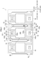
- FIG. 1 is a plan view of a fin (1) for a heat exchanger.
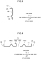
- FIG. 2 is a sectional end view taken along line II-II shown in FIG. 1 .
- FIG. 3 is a sectional end view taken along line III-III shown in FIG. 1 .
- FIG. 4 is a sectional end view taken along line IV-IV shown in FIG. 1 .
- FIG. 5 is a sectional end view taken along line V-V shown in FIG. 1 .
- an X-axis direction, a Y-axis direction, and a Z-axis direction are directions perpendicular to each other.
- the heat exchanger is provided in, for example, an indoor unit or outdoor unit of an air conditioner.
- the heat exchanger is a device that condenses or evaporates a refrigerant using air as a cooling source or a heating source, and is, for example, a component of a refrigerant circuit of a vapor compression refrigeration apparatus.
- the refrigerant circulating through the refrigerant circuit include a carbon dioxide refrigerant.
- the fin (1) includes a plurality of structural units (10).
- the structural units (10) are continuously arranged side by side in the X-axis direction.
- Each of the structural units (10) includes a plate-shaped portion (11), a continuous portion (12), a fin slit (13), a waffle portion (14), a first fin tab (15), a second fin tab (16), a flange (17), a drawn portion (18), and a dent.
- the plate-shaped portion (11) is a plate-shaped member having a thickness in the Z-axis direction.
- the plate-shaped portions (11) are arranged side by side in the X-axis direction.
- the continuous portion (12) is provided between an adjacent pair of plate-shaped portions (11).
- the continuous portion (12) is a plate-shaped member having a thickness in the Z-axis direction and surfaces that are perpendicular to the Z-axis direction on one side and the other side in the Z-axis direction.
- the continuous portion (12) is provided to be continuous with each of the adjacent plate-shaped portions (11).
- Each of the surfaces of the continuous portion (12) on the one side and the other side in the Z-axis direction is flush with the adjacent plate-shaped portions (11).
- the continuous portion (12) In the Y-axis direction, the continuous portion (12) has a smaller dimension than the plate-shaped portion (11).
- the continuous portion (12) is located between the plate-shaped portions (11) adjacent to each other.
- the continuous portion (12) is located on the other side of the fin (1) in the Y-axis direction.
- the fin slit (13) is a space formed between the adjacent plate-shaped portions (11) and the continuous portion (12).
- the fin slit (13) extends in the Y-axis direction. In the Y-axis direction, the fin slit (13) has a smaller dimension than the plate-shaped portion (11).
- the fin slit (13) is provided between the adjacent plate-shaped portions (11) on one side of the continuous portion (12) in the Y-axis direction.
- the fin slit (13) includes a first slit portion (131) and a second slit portion (132).
- the first slit portion (131) is a portion of the fin slit (13) located on one side in the Y-axis direction.
- the second slit portion (132) is a portion of the fin slit (13) located on the other side in the Y-axis direction.
- the second slit portion (132) is continuous with the first slit portion (131) and extends from the first slit portion (131) toward the other side in the Y-axis direction.
- a flat tube for sending a refrigerant is inserted into the fin slit (13).
- the dimension of the second slit portion (132) in the X-axis direction is set to match the dimension of the flat tube so that the flat tube can fit into the slit.
- the first slit portion (131) is configured to have a larger dimension than the second slit portion (132) in the X-axis direction so that the first slit portion (131) functions as a guide slit that guides the flat tube entering the fin slit (13). This allows easy insertion of the flat tube into the fin slit (13).
- the waffle portion (14) is provided on the plate-shaped portion (11), and is shaped to protrude from the plate-shaped portion (11) toward the one side in the Z-axis direction.
- the waffle portion (14) includes a center portion (141) located at the center of the plate-shaped portion (11) in the Y-axis direction, a first rib (142) formed on one side of the center portion (141) in the Y-axis direction, and a second rib (143) formed on the other side of the center portion (141) in the Y-axis direction.
- the center portion (141) is formed in a substantially rectangular shape, for example.
- the first rib (142) protrudes more toward the one side in the Z-axis direction than the center portion (141).
- the first rib (142) includes a first bridge portion (142a) and a pair of first extensions (142c).
- the first bridge portion (142a) is provided at an edge of the center portion (141) on the one side in the Y-axis direction, and extends in the X-axis direction.
- One of the pair of first extensions (142c) extends from an end of the first bridge portion (142a) on the one side in the X-axis direction to the one side in the Y-axis direction.
- the other of the pair of first extensions (142c) extends from an end of the first bridge portion (142a) on the other side in the X-axis direction to the one side in the Y-axis direction.
- the second rib (143) protrudes more toward the one side in the Z-axis direction than the center portion (141).
- the second rib (143) includes a second bridge portion (143a) and a pair of second extensions (143c).
- the second bridge portion (143a) is provided at an edge of the center portion (141) on the other side in the Y-axis direction, and extends in the X-axis direction.
- One of the second extensions (143c) in pair extends from an end of the second bridge portion (143a) on the one side in the X-axis direction to the other side in the Y-axis direction.
- the other of the second extensions (143c) in pair extends from an end of the second bridge portion (143a) on the other side in the X-axis direction to the other side in the Y-axis direction.
- the first fin tab (15) is provided in the plate-shaped portion (11) between the first extensions (142c) in pair.
- the first fin tab (15) includes a first through hole (151) and a first protrusion (152).
- the first through hole (151) is a hole penetrating the plate-shaped portion (11) in the Z-axis direction.
- the first through hole (151) is, for example, substantially rectangular.
- the first protrusion (152) is provided at an edge of the first through hole (151) on the other side in the X-axis direction, and is shaped to protrude from the plate-shaped portion (11) toward the one side in the Z-axis direction.
- the second fin tab (16) is provided in the plate-shaped portion (11) between the second extensions (143c) in pair.
- the second fin tab (16) includes a second through hole (161) and a second protrusion (162).
- the second through hole (161) is a hole penetrating the plate-shaped portion (11) in the Z-axis direction.
- the second through hole (161) is, for example, substantially rectangular.
- the second protrusion (162) is provided at an edge of the second through hole (161) on the one side in the X-axis direction, and is shaped to protrude from the plate-shaped portion (11) toward the one side in the Z-axis direction.
- the flange (17) has a shape obtained by bending part of the plate-shaped portion (11) at the edge of the fin slit (13) toward the one side in the Z-axis direction.
- the flange (17) is formed along an edge of the second slit portion (132) of the fin slit (13).
- the flange (17) has a substantially U-shape.
- the flange (17) maintains the strength of the fin (1), protecting the fin (1) from deformation when the flat tube is inserted into the fin slit (13).
- the flat tube inserted into the fin slit (13) can effectively make contact with the flange (17). This allows the flat tube to be effectively fixed to the fin (1) by, for example, brazing.
- the drawn portion (18) is provided in the continuous portion (12), and is shaped to protrude from the continuous portion (12) toward the one side in the Z-axis direction.
- the dent is provided in the continuous portion (12).
- the dent indicates a hit part of the continuous portion (12).
- the dent is in a location different from the drawn portion (18).
- the dent is provided, for example, in an area (19) of the continuous portion (12) located on the one side of the drawn portion (18) in the Y-axis direction.
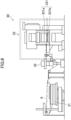
- FIG. 6 is a schematic view of a manufacturing apparatus (30) for the fin (1).
- the manufacturing apparatus (30) for the fin (1) will be described with reference to FIG. 6 .
- the manufacturing apparatus (30) for the fin (1) includes an uncoiler (31), a feeder (32), and a press (33).
- a plate-shaped fin material (A) is wound around the uncoiler (31).
- the fin material (A) is, for example, a member made of metal such as aluminum.
- the feeder (32) feeds the fin material (A) wound around the uncoiler (31) to the press (33).
- the feeder (32) includes, for example, a gripper feeder having a fixed clamp and a movable clamp.
- the feeder (32) feeds the fin material (A) to the press (33) by alternately repeating, for example, an action of moving the movable clamp holding the fin material (A) while the fixed clamp is releasing the fin material (A) and an action of returning the movable clamp releasing the fin material (A) to the former position while the fixed clamp is holding the fin material (A).
- the press (33) includes a die (331).
- the die (331) includes an upper die (331a) which can move up and down and a stationary lower die (331b).
- the lower die (331b) is disposed below the upper die (331a).
- the upper die (331a) and the lower die (331b) are suitably provided with punches and dies for forming the fin slit (13), the waffle portion (14), the first fin tab (15), the second fin tab (16), the flange (17), the drawn portion (18), and the dent.
- the upper die (331a) moves downward with the fin material (A) disposed on the lower die (331b)
- the fin material (A) is sandwiched between the upper die (331a) and the lower die (331b) and pressed by the die (331).
- components of the fin (1) such as the fin slit (13) and the waffle portion (14) are formed in the fin material (A) (see FIGS. 1 to 5 ).
- FIG. 7 is a flowchart of a method for manufacturing the fin (1).
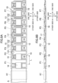
- FIGS. 8A and 8B are schematic views of a process of manufacturing the fin (1) by pressing using the die (331). The method for manufacturing the fin (1) will be described with reference to FIGS. 6 to 8B .
- the feeder (32) feeds the fin (1) to the one side in the X-axis direction.
- first point (P1) to a seventh point (P7) are set between the upper die (331a) and lower die (331b) of the die (331).
- the first point (P1) to the seventh point (P7) are located in the order of the first point (P1), the second point (P2), the third point (P3), the fourth point (P4), the fifth point (P5), the sixth point (P6), and the seventh point (P7) in the feeding direction of the fin (1) (toward the one side in the X-axis direction).
- the specific portion (A1) of the fin material (A) passes the first to seventh points (P1) to (P7) in the order of the first point (P1), the second point (P2), the third point (P3), the fourth point (P4), the fifth point (P5), the sixth point (P6), and the seventh point (P7).
- the specific portion (A1) of the fin material (A) that has reached the first point (P1) is pressed by the die (331) in Step S10. This pressing forms the waffle portion (14) in the specific portion (A1) (a waffle forming step).
- Step S20 the specific portion (A1) of the fin material (A) that has reached the second point (P2) is pressed by the die (331). This pressing forms the first fin tab (15), the second fin tab (16), and the first slit portion (131) of the fin slit (13) in the specific portion (A1) (a tab forming step).
- Step S30 the specific portion (A1) of the fin material (A) that has reached the third point (P3) is pressed by the die (331). This pressing forms the continuous portion (12) and the second slit portion (132) of the fin slit (13) in the specific portion (A1) (a cutting step).
- Step S40 the specific portion (A1) of the fin material (A) that has reached the fourth point (P4) is pressed by the die (331). This pressing forms the flange (17) in the specific portion (A1) (a flanging step).
- Step S50 the specific portion (A1) of the fin material (A) that has reached the fifth point (P5) is pressed by the die (331). This pressing forms the drawn portion (18) in the specific portion (A1) (a drawing step).
- Step S60 the specific portion (A1) of the fin material (A) that has reached the sixth point (P6) is pressed by the die (331). This pressing cuts an unwanted part of the specific portion (A1) so that the fin slit (13) communicates with external space (cut step).
- Step S70 the specific portion (A1) of the fin material (A) that has reached the seventh point (P7) is pressed by the die (331).
- This pressing hits the continuous portion (12) of the specific portion (A1), thereby forming a dent in the continuous portion (12) (hitting step).
- the dent is formed in the area (19) of the continuous portion (12).
- the continuous portion (12) is hit from the side toward which the drawn portion (18) protrudes.
- the structural unit (10) of the fin (1) is formed in the specific portion (A1) of the fin material (A).
- Each of the first to seventh points (P1) to (P7) is spaced apart from the adjacent point in the feeding direction by a distance L.
- the fin material (A) is fed by the distance L in the feeding direction (to the one side in the X-axis direction)
- the fin material (A) is pressed by the die (331).
- processes of Steps S10 to S70 described above are performed on the entire fin material (A).
- multiple structural units (10) are formed to be arranged side by side in the X-axis direction as illustrated in FIG. 1 , and thus, the fin (1) is manufactured.
- the drawn portion (18) protruding with respect to the continuous portion (12) is formed in the continuous portion (12) in the drawing step.
- the fin material (A) is warped to be convex toward the continuous portion (12) (see FIG. 9A ) as a result of the formation of the fin slit (13) and other components in the fin material (A)
- the warp toward the continuous portion (12) can be corrected by the drawn portion (18) formed in the continuous portion (12), thereby reducing the warp of the fin (1).
- the continuous portion (12) is excessively drawn by the formation of the drawn portion (18)
- the fin material (A) is warped to be convex toward the fin slit (13).
- the dimension and depth of the drawn portion (18) are controlled so that the continuous portion (12) is not excessively drawn by the formation of the drawn portion (18).
- the continuous portion (12) can be stretched by hitting the continuous portion (12) in the hitting step. This can correct the length of the fin (1) so that the fin (1) is not excessively shorter than a predetermined target length.
- the present disclosure is useful for a method for manufacturing a fin.
Landscapes
- Engineering & Computer Science (AREA)
- Mechanical Engineering (AREA)
- Physics & Mathematics (AREA)
- Thermal Sciences (AREA)
- General Engineering & Computer Science (AREA)
- Geometry (AREA)
- Heat-Exchange Devices With Radiators And Conduit Assemblies (AREA)
- Cooling Or The Like Of Semiconductors Or Solid State Devices (AREA)
- Cooling Or The Like Of Electrical Apparatus (AREA)
Abstract
Description
- The present disclosure relates to a method for manufacturing a fin.
-
Patent Document 1 discloses a mold apparatus for manufacturing a fin. The mold apparatus described inPatent Document 1 manufactures the fin by pressing a thin metal plate. When the fin is manufactured, pressure is applied to the thin metal plate by press working. However, the pressure is applied unevenly to part of the thin metal plate, and the fin may be warped. - Patent Document 1:
Japanese Patent No. 2695126 - An object of the present disclosure is to reduce warp of the fin.
- A first aspect is directed to a method for manufacturing a fin. The method for manufacturing the fin is a method for processing a plate-shaped fin material (A) into a fin (1) for a heat exchanger. The method for manufacturing the fin includes: a waffle forming step of forming a waffle portion and a plate-shaped portion (11) around the waffle portion in the fin material (A); a cutting step of forming a continuous portion (12) continuous with the plate-shaped portion (11) and a fin slit (13) for receiving a flat tube in a side of the plate-shaped portion (11) of the fin material (A); and a drawing step of forming a drawn portion (18) protruding with respect to the continuous portion (12) in the continuous portion (12).
- In the first aspect, warp of the fin (1) can be reduced.
- A second aspect is an embodiment of the first aspect. In the second aspect, the method further includes a hitting step of hitting the continuous portion (12).
- In the second aspect, the length of the fin (1) can be corrected so that the fin (1) is not excessively shorter than a predetermined target length.
- A third aspect is an embodiment of the second aspect. In the third aspect, in the hitting step, the continuous portion (12) is hit from a side toward which the drawn portion (18) protrudes.
- In the third aspect, the continuous portion (12) of the fin (1) can be hit from the side toward which the drawn portion (18) protrudes.
- A fourth aspect is an embodiment of any one of the first to third aspects. In the fourth aspect, the method further includes a flanging step of forming a flange (17) at an edge of the fin slit (13).
- In the fourth aspect, the flange (17) maintains the strength of the fin (1), thereby protecting the fin (1) from deformation when the flat tube is inserted into the fin slit (13).
- A fifth aspect is an embodiment of any one of the first to fourth aspects. In the fifth aspect, the method further includes: a step of forming a plurality of the fins (1) on the fin material (A); and a cut step of cutting a portion between the fins (1) adjacent to each other. The hitting step is performed after the cut step is finished.
- In the fifth aspect, the length of each of the fins (1) after the cutting can be corrected by the hitting step.
-
-
FIG. 1 is a plan view of a fin according to an embodiment. -
FIG. 2 is a sectional end view of the fin shown inFIG. 1 taken along line II-II. -
FIG. 3 is a sectional end view of the fin shown inFIG. 1 taken along line III-III. -
FIG. 4 is a sectional end view of the fin shown inFIG. 1 taken along line IV-IV -
FIG. 5 is a sectional end view of the fin shown inFIG. 1 taken along line V-V. -
FIG. 6 is a view of an apparatus for manufacturing the fin. -
FIG. 7 is a flowchart of a method for manufacturing the fin. -
FIG. 8A is a plan view of a process of manufacturing the fin.FIG. 8B is a front view of the process of manufacturing the fin. -
FIG. 9A is a view of a warped fin material.FIG. 9B is a view of a warped fin material. - Embodiments of the present disclosure will be described in detail below with reference to the drawings. The present disclosure is not limited to the embodiments shown below, and various changes can be made within the scope without departing from the technical concept of the present disclosure. Each of the drawings is intended to illustrate the present disclosure conceptually, and dimensions, ratios, or numbers may be exaggerated or simplified as necessary for the sake of ease of understanding.
- An exemplary embodiment will be described in detail below with reference to the drawings.
-
FIG. 1 is a plan view of a fin (1) for a heat exchanger.FIG. 2 is a sectional end view taken along line II-II shown inFIG. 1 .FIG. 3 is a sectional end view taken along line III-III shown inFIG. 1 .FIG. 4 is a sectional end view taken along line IV-IV shown inFIG. 1 .FIG. 5 is a sectional end view taken along line V-V shown inFIG. 1 . InFIGS. 1 to 5 , an X-axis direction, a Y-axis direction, and a Z-axis direction are directions perpendicular to each other. The heat exchanger is provided in, for example, an indoor unit or outdoor unit of an air conditioner. The heat exchanger is a device that condenses or evaporates a refrigerant using air as a cooling source or a heating source, and is, for example, a component of a refrigerant circuit of a vapor compression refrigeration apparatus. Examples of the refrigerant circulating through the refrigerant circuit include a carbon dioxide refrigerant. - As illustrated in
FIGS. 1 to 5 , the fin (1) includes a plurality of structural units (10). The structural units (10) are continuously arranged side by side in the X-axis direction. Each of the structural units (10) includes a plate-shaped portion (11), a continuous portion (12), a fin slit (13), a waffle portion (14), a first fin tab (15), a second fin tab (16), a flange (17), a drawn portion (18), and a dent. - The plate-shaped portion (11) is a plate-shaped member having a thickness in the Z-axis direction. The plate-shaped portions (11) are arranged side by side in the X-axis direction. The continuous portion (12) is provided between an adjacent pair of plate-shaped portions (11).
- The continuous portion (12) is a plate-shaped member having a thickness in the Z-axis direction and surfaces that are perpendicular to the Z-axis direction on one side and the other side in the Z-axis direction. The continuous portion (12) is provided to be continuous with each of the adjacent plate-shaped portions (11). Each of the surfaces of the continuous portion (12) on the one side and the other side in the Z-axis direction is flush with the adjacent plate-shaped portions (11). In the Y-axis direction, the continuous portion (12) has a smaller dimension than the plate-shaped portion (11). The continuous portion (12) is located between the plate-shaped portions (11) adjacent to each other. The continuous portion (12) is located on the other side of the fin (1) in the Y-axis direction.
- The fin slit (13) is a space formed between the adjacent plate-shaped portions (11) and the continuous portion (12). The fin slit (13) extends in the Y-axis direction. In the Y-axis direction, the fin slit (13) has a smaller dimension than the plate-shaped portion (11). The fin slit (13) is provided between the adjacent plate-shaped portions (11) on one side of the continuous portion (12) in the Y-axis direction. For the fin slit (13), one side and the other side in the X-axis direction are blocked by the plate-shaped portions (11), an opening is formed on one side in the Y-axis direction to open the one side, the other side in the Y-axis direction is blocked by the continuous portion (12), and one side and the other side in the Z-axis direction are open. The fin slit (13) includes a first slit portion (131) and a second slit portion (132). The first slit portion (131) is a portion of the fin slit (13) located on one side in the Y-axis direction. The second slit portion (132) is a portion of the fin slit (13) located on the other side in the Y-axis direction. The second slit portion (132) is continuous with the first slit portion (131) and extends from the first slit portion (131) toward the other side in the Y-axis direction.
- A flat tube for sending a refrigerant is inserted into the fin slit (13). The dimension of the second slit portion (132) in the X-axis direction is set to match the dimension of the flat tube so that the flat tube can fit into the slit. The first slit portion (131) is configured to have a larger dimension than the second slit portion (132) in the X-axis direction so that the first slit portion (131) functions as a guide slit that guides the flat tube entering the fin slit (13). This allows easy insertion of the flat tube into the fin slit (13).
- The waffle portion (14) is provided on the plate-shaped portion (11), and is shaped to protrude from the plate-shaped portion (11) toward the one side in the Z-axis direction. The waffle portion (14) includes a center portion (141) located at the center of the plate-shaped portion (11) in the Y-axis direction, a first rib (142) formed on one side of the center portion (141) in the Y-axis direction, and a second rib (143) formed on the other side of the center portion (141) in the Y-axis direction. The center portion (141) is formed in a substantially rectangular shape, for example. The first rib (142) protrudes more toward the one side in the Z-axis direction than the center portion (141). The first rib (142) includes a first bridge portion (142a) and a pair of first extensions (142c). The first bridge portion (142a) is provided at an edge of the center portion (141) on the one side in the Y-axis direction, and extends in the X-axis direction. One of the pair of first extensions (142c) extends from an end of the first bridge portion (142a) on the one side in the X-axis direction to the one side in the Y-axis direction. The other of the pair of first extensions (142c) extends from an end of the first bridge portion (142a) on the other side in the X-axis direction to the one side in the Y-axis direction. The second rib (143) protrudes more toward the one side in the Z-axis direction than the center portion (141). The second rib (143) includes a second bridge portion (143a) and a pair of second extensions (143c). The second bridge portion (143a) is provided at an edge of the center portion (141) on the other side in the Y-axis direction, and extends in the X-axis direction. One of the second extensions (143c) in pair extends from an end of the second bridge portion (143a) on the one side in the X-axis direction to the other side in the Y-axis direction. The other of the second extensions (143c) in pair extends from an end of the second bridge portion (143a) on the other side in the X-axis direction to the other side in the Y-axis direction.
- The first fin tab (15) is provided in the plate-shaped portion (11) between the first extensions (142c) in pair. The first fin tab (15) includes a first through hole (151) and a first protrusion (152). The first through hole (151) is a hole penetrating the plate-shaped portion (11) in the Z-axis direction. The first through hole (151) is, for example, substantially rectangular. The first protrusion (152) is provided at an edge of the first through hole (151) on the other side in the X-axis direction, and is shaped to protrude from the plate-shaped portion (11) toward the one side in the Z-axis direction.
- The second fin tab (16) is provided in the plate-shaped portion (11) between the second extensions (143c) in pair. The second fin tab (16) includes a second through hole (161) and a second protrusion (162). The second through hole (161) is a hole penetrating the plate-shaped portion (11) in the Z-axis direction. The second through hole (161) is, for example, substantially rectangular. The second protrusion (162) is provided at an edge of the second through hole (161) on the one side in the X-axis direction, and is shaped to protrude from the plate-shaped portion (11) toward the one side in the Z-axis direction.
- The flange (17) has a shape obtained by bending part of the plate-shaped portion (11) at the edge of the fin slit (13) toward the one side in the Z-axis direction. The flange (17) is formed along an edge of the second slit portion (132) of the fin slit (13). The flange (17) has a substantially U-shape. The flange (17) maintains the strength of the fin (1), protecting the fin (1) from deformation when the flat tube is inserted into the fin slit (13). The flat tube inserted into the fin slit (13) can effectively make contact with the flange (17). This allows the flat tube to be effectively fixed to the fin (1) by, for example, brazing.
- The drawn portion (18) is provided in the continuous portion (12), and is shaped to protrude from the continuous portion (12) toward the one side in the Z-axis direction. The dent is provided in the continuous portion (12). The dent indicates a hit part of the continuous portion (12). In the continuous portion (12), the dent is in a location different from the drawn portion (18). The dent is provided, for example, in an area (19) of the continuous portion (12) located on the one side of the drawn portion (18) in the Y-axis direction.
-
FIG. 6 is a schematic view of a manufacturing apparatus (30) for the fin (1). The manufacturing apparatus (30) for the fin (1) will be described with reference toFIG. 6 . - As illustrated in
FIG. 6 , the manufacturing apparatus (30) for the fin (1) includes an uncoiler (31), a feeder (32), and a press (33). A plate-shaped fin material (A) is wound around the uncoiler (31). The fin material (A) is, for example, a member made of metal such as aluminum. The feeder (32) feeds the fin material (A) wound around the uncoiler (31) to the press (33). The feeder (32) includes, for example, a gripper feeder having a fixed clamp and a movable clamp. The feeder (32) feeds the fin material (A) to the press (33) by alternately repeating, for example, an action of moving the movable clamp holding the fin material (A) while the fixed clamp is releasing the fin material (A) and an action of returning the movable clamp releasing the fin material (A) to the former position while the fixed clamp is holding the fin material (A). The press (33) includes a die (331). The die (331) includes an upper die (331a) which can move up and down and a stationary lower die (331b). The lower die (331b) is disposed below the upper die (331a). The upper die (331a) and the lower die (331b) are suitably provided with punches and dies for forming the fin slit (13), the waffle portion (14), the first fin tab (15), the second fin tab (16), the flange (17), the drawn portion (18), and the dent. When the upper die (331a) moves downward with the fin material (A) disposed on the lower die (331b), the fin material (A) is sandwiched between the upper die (331a) and the lower die (331b) and pressed by the die (331). As a result, components of the fin (1) such as the fin slit (13) and the waffle portion (14) are formed in the fin material (A) (seeFIGS. 1 to 5 ). -
FIG. 7 is a flowchart of a method for manufacturing the fin (1).FIGS. 8A and 8B are schematic views of a process of manufacturing the fin (1) by pressing using the die (331). The method for manufacturing the fin (1) will be described with reference toFIGS. 6 to 8B . In this embodiment, the feeder (32) feeds the fin (1) to the one side in the X-axis direction. - As illustrated in
FIGS. 6 ,8A, and 8B , seven points from a first point (P1) to a seventh point (P7) are set between the upper die (331a) and lower die (331b) of the die (331). The first point (P1) to the seventh point (P7) are located in the order of the first point (P1), the second point (P2), the third point (P3), the fourth point (P4), the fifth point (P5), the sixth point (P6), and the seventh point (P7) in the feeding direction of the fin (1) (toward the one side in the X-axis direction). - The following description will be made focusing on a specific portion (A1) of the fin material (A). While the fin material (A) is being fed, the specific portion (A1) of the fin material (A) passes the first to seventh points (P1) to (P7) in the order of the first point (P1), the second point (P2), the third point (P3), the fourth point (P4), the fifth point (P5), the sixth point (P6), and the seventh point (P7).
- As illustrated in
FIGS. 6 to 8B , the specific portion (A1) of the fin material (A) that has reached the first point (P1) is pressed by the die (331) in Step S10. This pressing forms the waffle portion (14) in the specific portion (A1) (a waffle forming step). - In Step S20, the specific portion (A1) of the fin material (A) that has reached the second point (P2) is pressed by the die (331). This pressing forms the first fin tab (15), the second fin tab (16), and the first slit portion (131) of the fin slit (13) in the specific portion (A1) (a tab forming step).
- In Step S30, the specific portion (A1) of the fin material (A) that has reached the third point (P3) is pressed by the die (331). This pressing forms the continuous portion (12) and the second slit portion (132) of the fin slit (13) in the specific portion (A1) (a cutting step).
- In Step S40, the specific portion (A1) of the fin material (A) that has reached the fourth point (P4) is pressed by the die (331). This pressing forms the flange (17) in the specific portion (A1) (a flanging step).
- In Step S50, the specific portion (A1) of the fin material (A) that has reached the fifth point (P5) is pressed by the die (331). This pressing forms the drawn portion (18) in the specific portion (A1) (a drawing step).
- In Step S60, the specific portion (A1) of the fin material (A) that has reached the sixth point (P6) is pressed by the die (331). This pressing cuts an unwanted part of the specific portion (A1) so that the fin slit (13) communicates with external space (cut step).
- In Step S70, the specific portion (A1) of the fin material (A) that has reached the seventh point (P7) is pressed by the die (331). This pressing hits the continuous portion (12) of the specific portion (A1), thereby forming a dent in the continuous portion (12) (hitting step). In this embodiment, the dent is formed in the area (19) of the continuous portion (12). In the hitting step of this embodiment, the continuous portion (12) is hit from the side toward which the drawn portion (18) protrudes. As a result, the structural unit (10) of the fin (1) (see
FIG. 1 ) is formed in the specific portion (A1) of the fin material (A). - Each of the first to seventh points (P1) to (P7) is spaced apart from the adjacent point in the feeding direction by a distance L. Each time the fin material (A) is fed by the distance L in the feeding direction (to the one side in the X-axis direction), the fin material (A) is pressed by the die (331). Thus, processes of Steps S10 to S70 described above are performed on the entire fin material (A). As a result, multiple structural units (10) are formed to be arranged side by side in the X-axis direction as illustrated in
FIG. 1 , and thus, the fin (1) is manufactured. - As described above, the drawn portion (18) protruding with respect to the continuous portion (12) is formed in the continuous portion (12) in the drawing step. Thus, although the fin material (A) is warped to be convex toward the continuous portion (12) (see
FIG. 9A ) as a result of the formation of the fin slit (13) and other components in the fin material (A), the warp toward the continuous portion (12) can be corrected by the drawn portion (18) formed in the continuous portion (12), thereby reducing the warp of the fin (1). If the continuous portion (12) is excessively drawn by the formation of the drawn portion (18), the fin material (A) is warped to be convex toward the fin slit (13). Thus, for the fin (1) with less warp as illustrated inFIG. 1 , the dimension and depth of the drawn portion (18) are controlled so that the continuous portion (12) is not excessively drawn by the formation of the drawn portion (18). - The continuous portion (12) can be stretched by hitting the continuous portion (12) in the hitting step. This can correct the length of the fin (1) so that the fin (1) is not excessively shorter than a predetermined target length.
- While the embodiments and the variations thereof have been described above, it will be understood that various changes in form and details may be made without departing from the spirit and scope of the claims (e.g., (1) below). The embodiments, the variation thereof, and the other embodiments may be combined and replaced with each other without deteriorating intended functions of the present disclosure.
- (1) In the method for manufacturing the fin (1), a plurality of fins (1) may be formed on a single fin material (A). In this case, the fins (1) are formed in parallel on the single fin material (A), and a cut step of cutting a portion between the adjacent fins (1) is added. Further, the hitting step is performed after the cut step, thereby correcting the length of each of the fins (1).
- As can be seen from the foregoing description, the present disclosure is useful for a method for manufacturing a fin.
-
- 1
- Fin
- 11
- Plate-Shaped Portion
- 12
- Continuous Portion
- 13
- Fin Slit
- 17
- Flange
- 18
- Drawn Portion
- A
- Fin Material
Claims (5)
- A method for manufacturing a fin by processing a plate-shaped fin material (A) into a fin (1) for a heat exchanger, the method comprising:a waffle forming step of forming a waffle portion and a plate-shaped portion (11) around the waffle portion in the fin material (A);a cutting step of forming a continuous portion (12) continuous with the plate-shaped portion (11) and a fin slit (13) for receiving a flat tube in a side of the plate-shaped portion (11) of the fin material (A); anda drawing step of forming a drawn portion (18) protruding with respect to the continuous portion (12) in the continuous portion (12).
- The method of claim 1, further comprising:
a hitting step of hitting the continuous portion (12). - The method of claim 2, wherein
in the hitting step, the continuous portion (12) is hit from a side toward which the drawn portion (18) protrudes. - The method of any one of claims 1 to 3, further comprising:
a flanging step of forming a flange (17) at an edge of the fin slit (13). - The method of any one of claims 1 to 4, further comprising:a step of forming a plurality of the fins (1) on the fin material (A); anda cut step of cutting a portion between the fins (1) adjacent to each other, whereinthe hitting step is performed after the cut step is finished.
Applications Claiming Priority (2)
| Application Number | Priority Date | Filing Date | Title |
|---|---|---|---|
| JP2022060674A JP7364953B1 (en) | 2022-03-31 | 2022-03-31 | Fin manufacturing method |
| PCT/JP2023/002278 WO2023188750A1 (en) | 2022-03-31 | 2023-01-25 | Method for manufacturing fin |
Publications (2)
| Publication Number | Publication Date |
|---|---|
| EP4461432A1 true EP4461432A1 (en) | 2024-11-13 |
| EP4461432A4 EP4461432A4 (en) | 2025-05-07 |
Family
ID=88200738
Family Applications (1)
| Application Number | Title | Priority Date | Filing Date |
|---|---|---|---|
| EP23778788.2A Pending EP4461432A4 (en) | 2022-03-31 | 2023-01-25 | METHOD FOR MANUFACTURING A RIB |
Country Status (5)
| Country | Link |
|---|---|
| US (1) | US20250012517A1 (en) |
| EP (1) | EP4461432A4 (en) |
| JP (1) | JP7364953B1 (en) |
| CN (1) | CN118871225B (en) |
| WO (1) | WO2023188750A1 (en) |
Family Cites Families (15)
| Publication number | Priority date | Publication date | Assignee | Title |
|---|---|---|---|---|
| JPS57202927A (en) * | 1981-06-05 | 1982-12-13 | Fujitsu Ltd | Eliminating method for strain of hoop band |
| JPS59141330A (en) * | 1983-01-27 | 1984-08-14 | Fujitsu Ltd | Production of comb-shaped rod |
| JP2695126B2 (en) | 1994-02-10 | 1997-12-24 | 日高精機株式会社 | Mold equipment |
| JP2012154491A (en) * | 2011-01-21 | 2012-08-16 | Daikin Industries Ltd | Air conditioner |
| JP5523495B2 (en) * | 2011-04-22 | 2014-06-18 | 三菱電機株式会社 | Finned tube heat exchanger and refrigeration cycle apparatus |
| WO2013160951A1 (en) * | 2012-04-26 | 2013-10-31 | 三菱電機株式会社 | Heat exchanger, method for manufacturing heat exchanger, and air conditioner |
| US10113812B2 (en) * | 2013-02-18 | 2018-10-30 | Denso Corporation | Heat exchanger and manufacturing method thereof |
| WO2015029145A1 (en) | 2013-08-27 | 2015-03-05 | 日高精機株式会社 | Device for manufacturing flat tube fin |
| WO2015058452A1 (en) * | 2013-10-21 | 2015-04-30 | 美的集团股份有限公司 | Heat exchanger fin and heat exchanger using heat exchanger fin |
| CN104482791A (en) * | 2014-12-02 | 2015-04-01 | 珠海格力电器股份有限公司 | Heat exchanger fin and heat exchanger |
| JP2017172810A (en) * | 2016-03-18 | 2017-09-28 | 三菱電機株式会社 | Fin tube heat exchanger manufacturing method and fin tube heat exchanger |
| CN106288911B (en) * | 2016-09-07 | 2018-08-14 | 珠海格力电器股份有限公司 | Fin and radiator comprising same |
| JP6897372B2 (en) | 2017-07-03 | 2021-06-30 | ダイキン工業株式会社 | Heat exchanger |
| JP7044991B2 (en) * | 2018-11-07 | 2022-03-31 | ダイキン工業株式会社 | Heat exchanger and air conditioner |
| CN111059953B (en) | 2019-12-03 | 2025-06-10 | 珠海格力电器股份有限公司 | Heat exchanger fin and heat exchanger |
-
2022
- 2022-03-31 JP JP2022060674A patent/JP7364953B1/en active Active
-
2023
- 2023-01-25 CN CN202380027285.5A patent/CN118871225B/en active Active
- 2023-01-25 EP EP23778788.2A patent/EP4461432A4/en active Pending
- 2023-01-25 WO PCT/JP2023/002278 patent/WO2023188750A1/en not_active Ceased
-
2024
- 2024-09-19 US US18/890,205 patent/US20250012517A1/en active Pending
Also Published As
| Publication number | Publication date |
|---|---|
| CN118871225A (en) | 2024-10-29 |
| US20250012517A1 (en) | 2025-01-09 |
| EP4461432A4 (en) | 2025-05-07 |
| CN118871225B (en) | 2025-03-21 |
| JP7364953B1 (en) | 2023-10-19 |
| WO2023188750A1 (en) | 2023-10-05 |
| JP2023158226A (en) | 2023-10-27 |
Similar Documents
| Publication | Publication Date | Title |
|---|---|---|
| JP5578378B2 (en) | Production equipment for heat exchanger fins | |
| US9816761B2 (en) | Method for manufacturing heat exchanger | |
| US10406588B2 (en) | Apparatus for inserting flattened tubes into heat exchanger fins | |
| US20160082555A1 (en) | Manufacturing method of heat exchanger and refrigeration cycle apparatus | |
| JPH1089884A (en) | Header plate made of aluminum substrate material | |
| US5797291A (en) | Die set for manufacturing heat exchanging fin of heat exchanger | |
| US20250012517A1 (en) | Method for manufacturing fin | |
| US10220431B2 (en) | Offset fin manufacturing method and offset fin manufacturing apparatus | |
| US20210138592A1 (en) | Method of manufacturing heat sink and heat sink | |
| JPH06154924A (en) | Press working method | |
| JP2003126929A (en) | Die for press working | |
| US20250300191A1 (en) | Method for Forming a Polar Plate of a Fuel Cell, and Associated Forming Plant | |
| WO2015029145A1 (en) | Device for manufacturing flat tube fin | |
| JP5623309B2 (en) | Modified cross-section copper alloy sheet excellent in press workability and manufacturing method thereof | |
| US20190301818A1 (en) | Metal plate burring method | |
| JP5881548B2 (en) | FIN AND TUBE HEAT EXCHANGER, AIR CONDITIONER EQUIPPED WITH THE SAME, AND METHOD FOR PRODUCING FIN AND TUBE HEAT EXCHANGER | |
| CN212703980U (en) | Accurate car cross slab right modulus of continuity of blank | |
| JP2015123455A (en) | Fin manufacturing apparatus | |
| JPS5841637A (en) | Molding method of corrugated fin | |
| KR102908493B1 (en) | Roll forming method | |
| KR20120114763A (en) | Tube-insertion hole for header pipe of regenerator and punch for processing thereof | |
| JP4765116B2 (en) | Manufacturing method of heat sink parts | |
| US20220111431A1 (en) | Device With Multiple Coined Areas Having Multiple Mechanical Properties | |
| JPS5982127A (en) | Production of needle-like fin group in heat exchanger | |
| CN121263259A (en) | Processing device, method for manufacturing metal member, and metal member |
Legal Events
| Date | Code | Title | Description |
|---|---|---|---|
| STAA | Information on the status of an ep patent application or granted ep patent |
Free format text: STATUS: THE INTERNATIONAL PUBLICATION HAS BEEN MADE |
|
| PUAI | Public reference made under article 153(3) epc to a published international application that has entered the european phase |
Free format text: ORIGINAL CODE: 0009012 |
|
| STAA | Information on the status of an ep patent application or granted ep patent |
Free format text: STATUS: REQUEST FOR EXAMINATION WAS MADE |
|
| 17P | Request for examination filed |
Effective date: 20240809 |
|
| AK | Designated contracting states |
Kind code of ref document: A1 Designated state(s): AL AT BE BG CH CY CZ DE DK EE ES FI FR GB GR HR HU IE IS IT LI LT LU LV MC ME MK MT NL NO PL PT RO RS SE SI SK SM TR |
|
| P01 | Opt-out of the competence of the unified patent court (upc) registered |
Free format text: CASE NUMBER: APP_953/2025 Effective date: 20250108 |
|
| A4 | Supplementary search report drawn up and despatched |
Effective date: 20250407 |
|
| RIC1 | Information provided on ipc code assigned before grant |
Ipc: B21D 22/02 20060101ALI20250401BHEP Ipc: B21D 31/06 20060101ALI20250401BHEP Ipc: B21D 28/26 20060101ALI20250401BHEP Ipc: B21D 28/10 20060101ALI20250401BHEP Ipc: B21D 22/20 20060101ALI20250401BHEP Ipc: B21D 19/08 20060101ALI20250401BHEP Ipc: F28F 1/32 20060101ALI20250401BHEP Ipc: F28F 1/30 20060101ALI20250401BHEP Ipc: F28F 1/02 20060101ALI20250401BHEP Ipc: F28D 1/053 20060101ALI20250401BHEP Ipc: B21D 53/08 20060101AFI20250401BHEP |
|
| DAV | Request for validation of the european patent (deleted) | ||
| DAX | Request for extension of the european patent (deleted) | ||
| STAA | Information on the status of an ep patent application or granted ep patent |
Free format text: STATUS: EXAMINATION IS IN PROGRESS |
|
| 17Q | First examination report despatched |
Effective date: 20260107 |