EP4461177A1 - Autonomes arbeitsgerät und antriebseinheit für ein autonomes arbeitsgerät - Google Patents
Autonomes arbeitsgerät und antriebseinheit für ein autonomes arbeitsgerät Download PDFInfo
- Publication number
- EP4461177A1 EP4461177A1 EP23172149.9A EP23172149A EP4461177A1 EP 4461177 A1 EP4461177 A1 EP 4461177A1 EP 23172149 A EP23172149 A EP 23172149A EP 4461177 A1 EP4461177 A1 EP 4461177A1
- Authority
- EP
- European Patent Office
- Prior art keywords
- toothing
- tooth element
- working device
- tooth
- gear
- Prior art date
- Legal status (The legal status is an assumption and is not a legal conclusion. Google has not performed a legal analysis and makes no representation as to the accuracy of the status listed.)
- Granted
Links
Images

Classifications
-
- A—HUMAN NECESSITIES
- A47—FURNITURE; DOMESTIC ARTICLES OR APPLIANCES; COFFEE MILLS; SPICE MILLS; SUCTION CLEANERS IN GENERAL
- A47L—DOMESTIC WASHING OR CLEANING; SUCTION CLEANERS IN GENERAL
- A47L9/00—Details or accessories of suction cleaners, e.g. mechanical means for controlling the suction or for effecting pulsating action; Storing devices specially adapted to suction cleaners or parts thereof; Carrying-vehicles specially adapted for suction cleaners
- A47L9/009—Carrying-vehicles; Arrangements of trollies or wheels; Means for avoiding mechanical obstacles
-
- A—HUMAN NECESSITIES
- A47—FURNITURE; DOMESTIC ARTICLES OR APPLIANCES; COFFEE MILLS; SPICE MILLS; SUCTION CLEANERS IN GENERAL
- A47L—DOMESTIC WASHING OR CLEANING; SUCTION CLEANERS IN GENERAL
- A47L11/00—Machines for cleaning floors, carpets, furniture, walls, or wall coverings
- A47L11/40—Parts or details of machines not provided for in groups A47L11/02 - A47L11/38, or not restricted to one of these groups, e.g. handles, arrangements of switches, skirts, buffers, levers
- A47L11/4063—Driving means; Transmission means therefor
- A47L11/4066—Propulsion of the whole machine
-
- A—HUMAN NECESSITIES
- A47—FURNITURE; DOMESTIC ARTICLES OR APPLIANCES; COFFEE MILLS; SPICE MILLS; SUCTION CLEANERS IN GENERAL
- A47L—DOMESTIC WASHING OR CLEANING; SUCTION CLEANERS IN GENERAL
- A47L5/00—Structural features of suction cleaners
- A47L5/12—Structural features of suction cleaners with power-driven air-pumps or air-compressors, e.g. driven by motor vehicle engine vacuum
- A47L5/22—Structural features of suction cleaners with power-driven air-pumps or air-compressors, e.g. driven by motor vehicle engine vacuum with rotary fans
-
- A—HUMAN NECESSITIES
- A47—FURNITURE; DOMESTIC ARTICLES OR APPLIANCES; COFFEE MILLS; SPICE MILLS; SUCTION CLEANERS IN GENERAL
- A47L—DOMESTIC WASHING OR CLEANING; SUCTION CLEANERS IN GENERAL
- A47L2201/00—Robotic cleaning machines, i.e. with automatic control of the travelling movement or the cleaning operation
Definitions
- the invention relates to a working device, in particular a cleaning device for autonomously cleaning a processing environment, with at least one housing, at least one drive unit and at least one control device.
- the drive unit has at least one motor and at least one drive wheel.
- the working device is designed and configured to move autonomously in a processing environment.
- Generic work devices are known in the prior art in a large number of designs. Such work devices are designed to move autonomously in a processing environment and to complete work tasks.
- An example of such work devices are cleaning devices that carry out cleaning tasks in a processing environment, transport robots in warehouse logistics or security robots that are used for monitoring purposes.
- a cleaning device is designed, for example, as a vacuum robot, mop robot or vacuum and mop robot.
- Such work devices usually have at least one control device that includes a data processing device and that uses a plurality of sensors to ensure navigation of the work device in the processing environment and to control the completion of work tasks in the processing environment.
- Tools designed as cleaning devices that are suitable for commercial applications usually have a larger construction volume, heavier weight, higher movement speeds and more power than cleaning devices used in households.
- there are increased requirements for operational safety e.g. with regard to the risk of falling on edges and stairs and when in contact with people or other tools.
- the installation space required for the required basic components is usually very large. Due to the space required for these basic components, the installation zones for accommodating additional equipment components, such as energy storage, electronics, work tools and sensors, are either limited or the size of the work equipment must be increased accordingly in order to accommodate all components in its entire construction volume.
- the invention is therefore based on the object of specifying a working device, in particular for commercial applications, in which the operational reliability is increased and at the same time the size of the working device is reduced.
- the drive unit has at least one self-locking gear.
- the gear has at least one first tooth element with a first toothing, in particular annular, and at least one second tooth element with a second toothing, in particular annular.
- the first tooth element is arranged within the second tooth element and the first toothing is at least partially in engagement with the second toothing.
- the drive wheel can be driven by the motor via the gear.
- the gear is advantageously arranged in the drive path between the motor and the drive wheel.
- the work device is designed for autonomous movement in a processing environment and for completing work tasks.
- the Work device designed as a cleaning device, transport device in transport logistics or safety robot for environmental monitoring.
- the work device is preferably designed as a cleaning device for cleaning a processing environment.
- the work device designed as a cleaning device is advantageously a cleaning device with a suction and/or wiping function, in particular a vacuum robot, a wiping robot or a vacuum and wiping robot.
- the working device has in particular at least one control device and a plurality of sensors which control the autonomous movement and cleaning of a processing environment by the cleaning device.
- the control device preferably has at least one data processing device with at least one processor and at least one memory.
- At least or exactly two drive units are arranged on the housing of the implement, each of which has at least one motor, in particular an electric motor, at least one self-locking gear and at least one drive wheel.
- the motor is preferably a brushless DC motor.
- the two motors of the drive units can be controlled independently of one another.
- Each motor drives at least indirectly at least or exactly one drive wheel via the gear.
- Each drive unit is, for example, at least partially movable essentially vertically, i.e. essentially orthogonal to a surface of the processing environment, on or at least partially in the housing, in particular an underside of the housing.
- Each drive unit preferably has a drive unit housing, which is advantageously attached to the housing of the working device.
- the working device has at least one energy storage device which is used to supply voltage to the working device, in particular to supply voltage to the control device and in particular to a working tool, in particular a cleaning tool, and is electrically connected in the housing.
- the energy storage device is designed as an accumulator with at least one cell, in particular a plurality of cells.
- Self-locking of the transmission of a drive unit means that the transmission stops when there is no more torque acting on the drive side, regardless of whether or not there is still a torque acting on the output side.
- the self-locking could also be referred to as self-braking.
- the transmission is designed in particular such that a torque on the output side cannot cause the transmission to move.
- the transmission advantageously stops when no more torque is introduced from the drive side.
- the transmission is designed in particular such that it cannot be reversed on the output side.
- the transmission advantageously has at least one drive side, to which the motor is connected, for example, and at least one output side, to which the drive wheel is connected, for example.
- the transmission is preferably designed to be statically and dynamically self-locking, so that the transmission in particular remains stationary when no torque is introduced from the drive side, even if there is still torque on the output side - here the drive wheel - and that it cannot be moved from the resting state by a torque introduced on the output side - here the drive wheel.
- the transmission has at least one first tooth element with a first toothing, in particular annular, and at least one second tooth element with a second toothing, in particular annular. The first tooth element is arranged so that it can move within the second tooth element.
- the first tooth element is held rotatably within the second tooth element.
- the second tooth element is preferably arranged in a stationary manner.
- the first toothing is at least partially in engagement with the second toothing.
- the first toothing and the second toothing are preferably ring-shaped, thus preferably forming a closed ring.
- the first toothed element rolls with its first toothing on the second toothing of the second toothed element or that the first toothing moves relative to the second toothing when the gear moves.
- the interaction of the toothings is preferably designed in such a way that the self-locking of the gear is achieved.
- the first toothing is an external toothing and the second toothing is an internal toothing.
- the first tooth element is designed as a toothed ring with an external toothing and/or the second tooth element is designed as a toothed ring with an internal toothing. It is also particularly provided that the first tooth element is designed as a toothed disk.
- a motor shaft of the motor is arranged coaxially with the wheel axle of the drive wheel.
- the motor is arranged in the drive unit in an axial line with the wheel axle of the drive wheel, although the motor shaft and the wheel axle of the drive wheel are not directly connected to one another.
- the self-locking gear for example a wave gear, is arranged between the motor and the drive wheel to ensure an emergency stop when the motor is switched off.
- the motor of the drive unit or the motors of the drive units can be switched off by the control device, for example using information, i.e. data, signals or measured values, from an environmental sensor system.
- the environmental sensor system comprises, for example, at least one optical sensor, in particular for monitoring the environment, and/or at least one distance sensor, with which in particular the distance to a surface of the processing environment is measured in order to detect building edges or stairs and prevent falls.
- the present invention has the advantage over the prior art that when the motor is switched off, the drive wheel is immediately blocked by the self-locking mechanism of the gear. A torque emanating from the drive wheel does not result in any further movement of the gear. Furthermore, the drive wheel or wheels cannot rotate when the implement is at a standstill. Due to the positive locking of the intermeshing teeth, no rotation can be introduced into the gear via the drive wheel, since the tooth flanks of the teeth of the first and second gearing press against each other. These properties of the gear mean that the presence of a special emergency brake is unnecessary, since all that is required to stop the implement in an emergency is to switch off the motor. Because a special emergency brake can be omitted, the required installation space and thus the size and weight of the implement are reduced compared to known implements.
- the first tooth element is elastically deformable, in particular radially elastically deformable.
- the first tooth element is coupled, for example, to the output shaft of the transmission or to the wheel axle of the drive wheel.
- the elastically deformable, first tooth element in the gear preferably realizes the self-locking of the gear.
- the first tooth element is, for example, movably held in the gear and, during a movement, only a part of its teeth engage with corresponding teeth of the second tooth element.
- the first tooth element for example as a toothed ring or toothed disk, rolls with its teeth on corresponding teeth in the gear.
- the first tooth element performs a wobbling movement within the second tooth element.
- an at least partially elastic deformation of the tooth element takes place.
- the tooth element is designed to be radially elastic, i.e., for example, deformable in relation to its diameter or in relation to its outer contour. In particular, an elastic deformation and a wobbling movement of the first tooth element occurs.
- a further embodiment of the working device provides that a tooth engagement between the first toothing and the second toothing can be effected by means of at least one guide means, in particular that the guide means has at least or exactly one rolling body, preferably at least or exactly two rolling bodies, or at least or exactly three rolling bodies, or at least one rotatable disk.
- the guide means preferably guides the first toothed element within the transmission.
- the guide means acts on the first toothed element in such a way that the guide means causes an engagement, in particular local, of teeth of the first toothing with teeth of the second toothing.
- the guide means causes an engagement between the first toothing and the second toothing in the circumference of a contact surface between the guide means and the first toothed element.
- the guide means preferably acts on the first toothed element in such a way that the first toothing moves relative to the second toothing when the transmission is driven by the motor.
- the guide means is advantageously movable, in particular rotatable, by the motor.
- the guide means is designed as a rolling body, e.g. as a roller or roller bearing, and acts on the first toothed element from an inner side.
- the first toothed element is designed in particular as a toothed ring with an external toothing.
- the first toothing of the first toothed element is pressed by the rolling body into engagement with the second toothing of the second toothed element.
- the rolling body is held rotatably around the motor shaft of the motor, whereby the motor shaft does not coincide with a rolling axis of the rolling body.
- the rolling body can, for example, cause the first toothed element to roll on the second toothed element and thus cause a relative movement between the first and second toothing.
- the rotation resulting from the movement of the first toothed element is, for example, transmitted to the wheel axle of the drive wheel.
- the rotation is transmitted, for example, by means of a plain bearing described below, in particular to enable a wobbling movement of the first tooth element.
- a balancing weight is connected to the rolling body in order to compensate for an imbalance caused by the rotation of the rolling body.
- the guide means has at least two rolling bodies, and that the rolling bodies are held in such a way that they can rotate about a common axis that is positioned between the rolling bodies.
- Each rolling body itself can rotate about an axis of rotation.
- a rotation of the rolling bodies - including the respective axis of rotation - about the common axis of the rolling bodies can be effected by the motor.
- a rotation of each rolling body about its own axis of rotation is achieved, for example, by rolling, in particular on an inner surface of the first tooth element.
- the rolling bodies are arranged in such a way that they bring the first toothing of the first tooth element into engagement with the second toothing of the second tooth element opposite one another.
- the first toothing is in engagement with the second toothing, for example, at least in the area of the rolling bodies or only in the area of the rolling bodies. It is provided that a part of the first toothing and the second toothing in the areas between the rolling bodies is at least partially in engagement with one another, in particular depending on the wobbling movement of the first tooth element relative to the second tooth element.
- the engagement of the first toothing in the second toothing can be effected by a rotatably mounted disk, in particular an eccentrically mounted disk or an oval disk.
- the disk is preferably arranged in the gear unit within the first tooth element, so that a rotation of the disk caused by the motor causes an engagement, in particular local, of the first toothing with the second toothing.
- the guide means for example a disc or a ring, slides along the first tooth element.
- a further embodiment of the tool provides that force is transmitted between the first tooth element and the second tooth element only via one to 15 teeth. It is provided that, especially when more than one to 15 teeth are engaged, force is actually transmitted only via the limited number of teeth. For example, it is also provided that force is transmitted via at least or exactly one tooth or via at least or exactly two teeth or via at least or exactly three teeth. It is also preferably provided that force is transmitted between the first toothing and the second toothing via 1.7% to 17% of the teeth of the first toothing.
- the first toothing and the second toothing have a different number of teeth.
- the first toothing has at least or exactly one tooth less, at least or exactly two teeth less, at least or exactly three teeth less than the second toothing.
- the tooth jump is particularly accompanied by a deformation of the first tooth element, which is advantageously designed to be deformable due to its material properties and geometry. It is preferably provided that the tooth jump is brought about by the wobbling movement and/or the deformation of the first tooth element.
- the position of the possible tooth jump can be determined by the position of the guide means and the first tooth element at the time of assembly.
- the assignment of the tooth jump position to one of the two areas in which the teeth do not engage remains constant as long as the guide means and the first tooth element are not dismantled.
- a design with a two-tooth difference between the gear teeth is subject to the same conditions in a system with two rolling elements as a guide.
- a decision can be made as to whether the tooth jump should be in a single area between the two areas with engagement, or whether there should be a tooth jump of one tooth spacing in each of the two areas between the areas with engagement.
- the difference lies in the required deformation, because a tooth jump of two or more teeth in just one area requires a greater deformation movement of the first tooth element, which can affect the service life of the gear depending on the material and/or the size of the transmitted torque.
- the first toothing has exactly one tooth less, for example 59 teeth, than the second toothing, for example 60 teeth.
- the first tooth element rotates by one tooth width relative to the second toothing when at least one toothed area between the two toothings has completed one revolution in the second toothing. After 59 revolutions of the toothed area, the first tooth element has then rotated, for example, once around the own axis - if necessary taking into account any wobbling movement.
- the guide means is designed as an elliptical disk that slides along the inside of the first tooth element, at least one toothed area has moved around once after the disk has rotated.
- the guide means has, for example, two rotatable roller bodies within the first tooth element
- the first tooth element rotates by one tooth width relative to the second toothing for each revolution of the roller bodies about the common axis arranged between the roller bodies, thus completing a full revolution after 59 revolutions of the roller bodies about the common axis arranged between the roller bodies or after 59 revolutions of the motor axis.
- the roller bodies are coupled to the motor and can be rotated by the motor about an axis positioned between the roller bodies. This results in a gear reduction of 59:1.
- Each roller body rotates when rotating about the common axis, particularly depending on its diameter, with any number of revolutions about its respective axis of rotation.
- the drive wheel can be rotated with the first toothed element, for example via at least one plain bearing.
- the second toothed element is advantageously held stationary.
- the first toothing moves relative to the second toothing - caused by the tooth overlap.
- the resulting rotation of the first tooth element is transmitted to the drive wheel as a rotary movement, for example with at least one plain bearing.
- the first toothed element is designed as a toothed ring and the second toothed element as a toothed ring.
- the first toothed ring is held in the second toothed ring and is pressed by the guide means, for example in the form of two rolling bodies acting opposite one another on the inner circumference of the first toothed ring, into engagement with the second toothing of the second toothed ring with an internal toothing.
- the first toothed ring and the second toothed ring advantageously have a different number of teeth, so that the tooth jump described above occurs when the guide means moves.
- the second gear ring is held in place so that when the guide body rotates due to the motor, the first gear ring rotates in the second gear ring.
- the movement of the first gear ring in the second gear ring is transferred to the wheel axle of the drive wheel.
- the gear system designed in this way has a reduction ratio of 59:1, for example, and is self-locking.
- first tooth element and/or the second tooth element is/are made at least partially, in particular completely, from polyoxymethylene (POM), polypropylene carbonate (PPC), polyamide (PA), polypropylene (PP), a thermoplastic elastomer and/or a silicone.
- POM polyoxymethylene
- PPC polypropylene carbonate
- PA polyamide
- PP polypropylene
- thermoplastic elastomer a thermoplastic elastomer and/or a silicone.
- the first tooth element is made as a first toothed ring with external teeth from polyoxymethylene (POM), polypropylene carbonate (PPC), polyamide (PA), polypropylene (PP), a thermoplastic elastomer and/or a silicone and/or the second tooth element is made as a second toothed ring with internal teeth from polyoxymethylene (POM), polypropylene carbonate (PPC), polyamide (PA), polypropylene (PP), a thermoplastic elastomer and/or a silicone.
- POM polyoxymethylene
- PPC polypropylene carbonate
- PA polyamide
- PP polypropylene
- a thermoplastic elastomer and/or a silicone a silicone.
- the transmission has at least one driver and the driver is coupled to the first toothed element.
- the driver is advantageously connected to the wheel axle of the drive wheel.
- the driver has a disk-shaped base body.
- the first toothed element is designed as a first toothed ring with external teeth and the driver is arranged at least partially within the toothed ring, in particular without disturbing a movement of the guide means.
- the driver is provided with at least one plain bearing with the first toothed element, in particular the first toothed ring, is coupled.
- the use is advantageous if the first tooth element deforms during rotation, so that the deformation and any wobbling movement do not affect the driver.
- the driver has a disk-shaped base body from which at least one pin extends in the radial direction.
- the pin engages with a pin bearing arranged on the inner circumference of the first tooth element, in particular the first toothed ring, for example in the form of two projections arranged parallel to one another.
- the pin and the pin bearing form the plain bearing, which compensates in particular for deformations in the radial direction, but transmits rotation to the driver and thus to the drive wheel.
- the driver is connected to the first toothed element by at least four plain bearings, which are in particular evenly distributed over the circumference. This improves the transmission of force to the driver.
- the first tooth element is formed in one piece with the driver.
- the first tooth element and the driver are connected to one another via elastic elements.
- the elastic elements compensate in particular for a deformation and/or a wobbling movement of the first tooth element, in particular of the first tooth ring, in the radial direction, but transmit the rotation of the first tooth element to the driver.
- the first tooth element and the driver are manufactured as a two-component component, for example with a harder component for the driver and the first tooth element and a softer component for the elastic elements in between.
- This design has the advantage that the number of components is reduced and the loss-producing friction in the plain bearings is avoided.
- a further embodiment of the working device provides that the drive unit on the working device is movable, for example pivotable and/or translational is held in a movable manner.
- Each working unit is movably attached to an underside of the housing of the working device, for example with a pivot bearing.
- the drive unit is pressed into a position pivoted against the underside of the working device by a spring preload between the housing and an arm that can swing around the pivot bearing.
- the drive unit is held on an underside of the housing of the working unit so that it can move in translation.
- the translational mobility is realized, for example, by means of bending beams and/or plain bearings.
- the control device In order to switch off the power to the motor in critical operational situations, the control device must be able to identify such situations.
- the work device has at least one environmental sensor system.
- the control device is designed to switch off the power to at least one motor or all motors of all drive units using information, e.g. at least one measured value, at least one signal or data, from the environmental sensor system if the information indicates an operationally critical situation, for example damage to the environment or the work device.
- the environmental sensor system has at least one sensor, preferably a plurality of sensors, with which the environment of the work device can be monitored.
- the environmental sensor system comprises at least one optical sensor and/or at least one acoustic sensor and/or at least one electromagnetic sensor.
- control unit processes information from the environmental sensor system and can identify a critical operating situation that requires the engine to be switched off based on the exceedance of threshold values and/or a profile of criteria of predefined situations.
- the invention further relates to a drive unit for a working device, wherein the drive unit is designed in particular according to one of the described embodiments.
- the drive unit has, for example, at least one motor and at least one drive wheel and is characterized in that at least one self-locking gear is present, wherein the drive wheel can be driven by the motor via the gear.
- the gear has at least one first tooth element with a first toothing, in particular annular, and at least one second tooth element with a second toothing, in particular annular.
- the first tooth element is arranged within the second tooth element.
- the first toothing is at least partially in engagement with the second toothing.
- Fig. 1 shows an embodiment of a working device 1 in a perspective side view.
- the working device 1 has a housing 2, two drive units 3 arranged on the underside of the housing 2 and at least one control device arranged in the housing 2.
- the working device 1 is designed as a cleaning device, namely as a vacuum robot, and can move autonomously in a processing environment 6.
- the working device 1 has an environmental sensor system 24 with which the processing environment 6 can be continuously recorded.
- the control device is set up to switch off the power to at least one motor 4 or all motors 4 of all drive units 3 using information, e.g. at least one measured value, at least one signal or data, from the environmental sensor system 24 if the information indicates an operationally critical situation, for example damage to the environment or the work device 1.
- FIG. 2 shows a first section through the embodiment along a motor shaft 9 of the motor 4
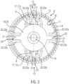
- Fig. 3 shows a second section through the embodiment orthogonal to the motor shaft 9.
- Each drive unit 3 has a motor 4, a drive wheel 5 and a self-locking gear 8.
- the self-locking gear 8 is arranged between the motor 4 and the drive wheel 5 in such a way that the drive wheel 5 can be driven with the motor 4 via the gear 8.
- the motor 4 is designed as a brushless DC motor.
- the gear 8 has a gear housing 8a in which the components of the gear 8 are held.
- the gearbox 8 according to Fig. 2 and 3 is self-locking, in particular statically and dynamically self-locking, so that it can be moved by the motor 4, in particular by the motor shaft 9 of the motor 4, i.e. from the drive side, but cannot be moved from the output side, namely the wheel axle 10 of the drive wheel 5.
- the wheel axle 10 is in Fig. 2 only presented as an approach.
- the gear 8 has, in particular for realizing the self-locking, an elastically deformable, first tooth element 11 with a first toothing 12 designed as an external toothing.
- the first tooth element 11 is designed as a first toothed ring.
- the first toothing 12 of the first tooth element 11 interacts at least locally, namely in two oppositely arranged areas 13, with a second toothing 15 of a second tooth element 14.
- the second tooth element 14 is designed as a second toothed ring with internal toothing, which here forms the second toothing 15.
- the second tooth element 14 is firmly connected to the housing 8a of the gear 8 or is designed as one piece with the housing 8a of the gear 8.
- the motor shaft 9 of the motor 4 is arranged coaxially in the axial direction one behind the other with the wheel axle 10 of the drive wheel 5.
- a guide bearing 16 is connected to the motor shaft 9 in a rotationally fixed manner, on which a guide means 17 in the form of two rolling elements 17a is arranged.
- the rolling elements 17a can be rotated about the motor shaft 9 by means of the motor 4 and the guide bearing 16, each rolling element 17a in turn being mounted rotatably about a rolling element axis R on a bearing projection 7 of the guide bearing 16.
- the rolling elements 17a are arranged in the gear 8 in such a way that they cause the first toothing 12 to mesh with the second toothing 15 at least in the opposite areas 13.
- the toothing 12, 15 In the areas of the toothing 12, 15 arranged between the areas 13, the toothing 12, 15 do not mesh or only partially mesh. According to Fig. 2 the gears 12, 15 engage at least partially with each other in the area shown on the right between the areas 13. In particular, in the areas arranged between the areas 13, no force is transmitted between the gears 12, 15. The local engagement of the first gear 12 in the second gear 15 as well as the non-engagement or only partial engagement of the gears 12, 15 in the areas in between is in Fig. 3 shown schematically.
- the first tooth element 11 which is designed as a first toothed ring, is elastically designed and is elastically deformed by the action of the guide means 17 or the action of the rolling bodies 17a.
- the first toothing 12 has exactly one tooth less than the second toothing 15.
- the first toothing 12 has 59 teeth and the second toothing 15 has 60 teeth.
- a driver 19 is arranged and centrally mounted in the gear 8.
- the driver 19 is positively connected to the wheel axle 10 of the drive wheel 5 and transmits its movement to the Wheel axle 10.
- the driver 19 has a substantially disc-shaped base body 20.
- each pin bearing 22 consists of two projections 22a that are arranged essentially parallel to one another and extend radially inwards from the first tooth element 11.
- the pins 21 and the pin bearings 22 together form a total of four plain bearings 23 that are evenly distributed over the circumference.
- the plain bearings 23 have the function of decoupling the wobbling movement and deformation of the first tooth element 11 from the rotational movement, so that only the pure rotational movement of the first tooth element 11 is transmitted to the driver 19. The plain bearings 23 therefore ensure radial compensation without interrupting the power transmission.
- the gear 8 designed in this way has a self-locking mechanism, so that rotation of the wheel axle 10 stops immediately when the motor 4 is de-energized.
- the self-locking mechanism of the gear 8 is achieved by the fact that when a torque is introduced via the wheel axle 10, the force would be transmitted to the first tooth element 11 via the plain bearings 23, but then the first toothing 12 could not move relative to the second toothing 15 because the tooth flanks of the teeth of the toothings 12, 15 are in contact with one another.
- a gear of this type is also referred to as a wave gear. Since the gear 8 is self-locking, i.e. cannot be set in rotation via the wheel axle 10 and stops when the motor 4 is switched off, the self-locking gear 8 fulfills the function of an emergency brake for the work tool 1.
Landscapes
- Engineering & Computer Science (AREA)
- Mechanical Engineering (AREA)
- Lifting Devices For Agricultural Implements (AREA)
- Transplanting Machines (AREA)
- Control Of Position, Course, Altitude, Or Attitude Of Moving Bodies (AREA)
- Retarders (AREA)
Abstract
Description
- Die Erfindung betrifft ein Arbeitsgerät, insbesondere ein Reinigungsgerät zum autonomen Reinigen einer Bearbeitungsumgebung, mit mindestens einem Gehäuse, mindestens einer Antriebseinheit und mindestens einer Steuereinrichtung. Die Antriebseinheit weist mindestens einen Motor und mindestens ein Antriebsrad auf. Das Arbeitsgerät ist dazu ausgebildet und eingerichtet, sich in einer Bearbeitungsumgebung autonom fortzubewegen.
- Gattungsgemäße Arbeitsgeräte sind im Stand der Technik in einer Vielzahl von Ausgestaltungen bekannt. Derartige Arbeitsgeräte sind dazu ausgebildet, sich in einer Bearbeitungsumgebung autonom fortzubewegen und Arbeitsaufgaben zu erledigen. Ein Beispiel für solche Arbeitsgeräte sind Reinigungsgeräte, die in einer Bearbeitungsumgebung Reinigungsaufgaben erledigen, Transportroboter in der Lagerlogistik oder Sicherheitsroboter, die zu Überwachungszwecken eingesetzt werden. Ein Reinigungsgerät ist beispielsweise als Saugroboter, Wischroboter oder Saug- und Wischroboter ausgebildet. Üblicherweise verfügen derartige Arbeitsgeräte über mindestens eine Steuereinrichtung, die eine Datenverarbeitungseinrichtung umfasst, und die mit einer Mehrzahl von Sensoren eine Navigation des Arbeitsgerätes in der Bearbeitungsumgebung gewährleistet sowie das Erledigen von Arbeitsaufgaben in der Bearbeitungsumgebung steuert.
- Als Reinigungsgeräte ausgebildete Arbeitsgeräte, die für gewerbliche Anwendungen geeignet sind, verfügen gegenüber Reinigungsgeräten, die in Haushalten eingesetzt werden, üblicherweise über ein größeres Bauvolumen, höheres Gewicht, höhere Bewegungsgeschwindigkeiten und mehr Leistung. Darüber hinaus werden erhöhte Anforderungen an die Betriebssicherheit gestellt, z. B. hinsichtlich der Absturzgefahr an Kanten und Treppen sowie bei Kontakt zu Personen oder weiteren Arbeitsgeräten.
- Für die Betriebssicherheit eines Arbeitsgerätes ist es daher von gesteigerter Bedeutung, dass bei Erkennen eines Hindernisses oder einer kritischen Betriebssituation eine unverzügliche Reaktion des sich bewegenden Arbeitsgerätes erforderlich ist, um eine Schädigung im Umfeld des Arbeitsgerätes und/oder eine Beschädigung des Arbeitsgerätes zu verhindern.
- Bei bekannten Arbeitsgeräten ist der Bedarf an Bauraum für die erforderlichen Grundkomponenten zudem üblicherweise sehr groß. Infolge des für diese Grundkomponenten benötigten Raumes sind die Einbauzonen für die Unterbringung weiterer Geräteeinbauten, wie Energiespeicher, Elektronik, Arbeitswerkzeuge und Sensorik, entweder limitiert oder die Größe des Arbeitsgerätes muss zur Unterbringung aller Komponenten in seinem gesamten Bauvolumen entsprechend vergrößert werden.
- Der Erfindung liegt daher die Aufgabe zugrunde, ein Arbeitsgerät, insbesondere für gewerbliche Anwendungen, anzugeben, bei dem die Betriebssicherheit gesteigert und gleichzeitig die Größe des Arbeitsgeräts reduziert ist.
- Die vorgenannte Aufgabe ist bei einem gattungsgemäßen Arbeitsgerät gemäß dem Kennzeichnungsteil des Anspruchs 1 dadurch gelöst, dass die Antriebseinheit mindestens ein selbsthemmendes Getriebe ausweist. Das Getriebe weist mindestens ein erstes Zahnelement mit einer, insbesondere ringförmigen, ersten Verzahnung und mindestens ein zweites Zahnelement mit einer, insbesondere ringförmigen, zweiten Verzahnung auf. Das erste Zahnelement ist innerhalb des zweiten Zahnelements angeordnet und die erste Verzahnung ist zumindest teilweise im Eingriff mit der zweiten Verzahnung. Das Antriebsrad ist mit dem Motor über das Getriebe antreibbar. Das Getriebe ist vorteilhaft im Antriebspfad zwischen Motor und Antriebrad angeordnet.
- Das Arbeitsgerät ist zur autonomen Fortbewegung in einer Bearbeitungsumgebung und zur Erledigung von Arbeitsaufgaben ausgebildet. Beispielsweise ist das Arbeitsgerät als Reinigungsgerät, Transportgerät in der Transportlogistik oder Sicherheitsroboter zur Umgebungsüberwachung ausgebildet. Vorzugsweise ist das Arbeitsgerät als Reinigungsgerät zum Reinigen einer Bearbeitungsumgebung ausgebildet. Bei dem als Reinigungsgerät ausgebildeten Arbeitsgerät handelt es sich vorteilhaft um ein Reinigungsgerät mit Saug- und/oder Wischfunktion, insbesondere um einen Saugroboter, einen Wischroboter oder einen Saug- und Wischroboter.
- Das Arbeitsgerät verfügt insbesondere über mindestens eine Steuereinrichtung und eine Mehrzahl an Sensoren, die das autonome Bewegen und Reinigen einer Bearbeitungsumgebung durch das Reinigungsgerät steuern. Die Steuereinrichtung weist vorzugsweise mindestens eine Datenverarbeitungseinrichtung mit mindestens einem Prozessor und mindestens einem Speicher auf.
- An dem Gehäuse des Arbeitsgeräts sind beispielsweise mindestens oder genau zwei Antriebseinheiten angeordnet, die jeweils mindestens einen Motor, insbesondere einen Elektromotor, mindestens ein selbsthemmendes Getriebe und mindestens ein Antriebsrad aufweisen. Der Motor ist vorzugsweise ein bürstenloser Gleichstrommotor. Die beiden Motoren der Antriebseinheiten sind unabhängig voneinander ansteuerbar. Jeder Motor treibt über das Getriebe zumindest mittelbar mindestens oder genau ein Antriebsrad an.
- Jede Antriebseinheit ist beispielsweise zumindest teilweise im Wesentlichen vertikal bewegbar, also im Wesentlichen orthogonal zu einer Oberfläche der Bearbeitungsumgebung, an bzw. zumindest teilweise in dem Gehäuse, insbesondere einer Unterseite des Gehäuses, angeordnet. Jede Antriebseinheit weist vorzugsweise ein Antriebseinheitsgehäuse auf, das vorteilhaft an dem Gehäuse des Arbeitsgeräts befestigt ist.
- Des Weiteren weist das Arbeitsgerät mindestens einen Energiespeicher auf, der zur Spannungsversorgung des Arbeitsgerätes, insbesondere zur Spannungsversorgung der Steuereinrichtung und insbesondere eines Arbeitswerkzeugs, insbesondere eines Reinigungswerkzeugs, ausgebildet und im Gehäuse elektrisch verschaltet ist. Beispielsweise ist der Energiespeicher als Akkumulator mit mindestens einer Zelle, insbesondere einer Mehrzahl von Zellen, ausgebildet.
- Eine Selbsthemmung des Getriebes einer Antriebseinheit nach dem Verständnis der vorliegenden Erfindung bedeutet, dass das Getriebe stehenbleibt, wenn an der Antriebsseite kein Drehmoment mehr wirkt, unabhängig davon, ob an der Abtriebsseite noch ein Drehmoment wirkt oder nicht. Die Selbsthemmung könnte auch als Selbstbremsung bezeichnet werden. Das Getriebe ist insbesondere so ausgebildet, dass ein Drehmoment an der Abtriebsseite keine Bewegung des Getriebes bewirken kann. Das Getriebe bleibt vorteilhaft stehen, wenn von der Antriebsseite kein Drehmoment mehr eingeleitet wird. Das Getriebe ist insbesondere derart ausgebildet, dass es auf der Abtriebsseite nicht rückdrehbar ist.
- Das Getriebe weist vorteilhaft mindestens eine Antriebsseite auf, mit der beispielsweise der Motor verbunden ist, und mindestens eine Abtriebsseite auf, mit der beispielsweise das Antriebsrad verbunden ist. Das Getriebe ist vorzugsweise statisch und dynamisch selbsthemmend ausgebildet, so dass das Getriebe insbesondere stehen bleibt, wenn kein Drehmoment von der Antriebsseite eingeleitet wird, selbst wenn an der Abtriebsseite - hier dem Antriebsrad - noch ein Drehmoment anliegt, und dass es aus dem ruhenden Zustand nicht durch ein an der Abtriebsseite - hier dem Antriebsrad - eingeleiteten Drehmoment bewegbar ist. Das Getriebe weist mindestens ein erstes Zahnelement mit einer, insbesondere ringförmigen, ersten Verzahnung und mindestens ein zweites Zahnelement mit einer, insbesondere ringförmigen, zweiten Verzahnung auf. Das erste Zahnelement ist innerhalb des zweiten Zahnelements bewegbar angeordnet. Beispielsweise ist das erste Zahnelement innerhalb des zweiten Zahnelements rotierbar gehalten. Das zweite Zahnelement ist vorzugsweise ortsfest angeordnet. Die erste Verzahnung ist zumindest teilweise im Eingriff mit der zweiten Verzahnung. Die erste Verzahnung und die zweite Verzahnung sind vorzugsweise ringförmig ausgebildet, bilden also vorzugsweise einen geschlossenen Ring aus.
- Beispielsweise ist vorgesehen, dass das erste Zahnelement mit seiner ersten Verzahnung auf der zweiten Verzahnung des zweiten Zahnelements abrollt bzw. sich die erste Verzahnung bei einer Bewegung des Getriebes relativ zur zweiten Verzahnung bewegt. Das Zusammenwirken der Verzahnungen ist vorzugsweise derart ausgebildet, dass darüber die Selbsthemmung des Getriebes verwirklicht wird.
- Es ist insbesondere vorgesehen, dass die erste Verzahnung eine Außenverzahnung und die zweite Verzahnung eine Innenverzahnung ist. Beispielsweise ist das erste Zahnelement als Zahnring mit einer Außenverzahnung und/oder das zweite Zahnelement als Zahnring mit einer Innenverzahnung ausgebildet. Es ist insbesondere auch vorgesehen, dass das erste Zahnelement als Zahnscheibe ausgebildet ist.
- Insbesondere für die Reduzierung des Bauraums hat es sich als vorteilhaft herausgestellt, wenn vorgesehen ist, dass eine Motorwelle des Motors koaxial mit der Radachse des Antriebsrades angeordnet ist. Der Motor ist in der Antriebseinheit räumlich in einer Achslinie mit der Radachse des Antriebsrades angeordnet, wobei jedoch die Motorwelle und die Radachse des Antriebsrades nicht direkt durchgehend miteinander verbunden sind. Zwischen dem Motor und dem Antriebsrad ist das selbsthemmende Getriebe, beispielsweise ein Wellgetriebe, angeordnet, um einen Nothalt beim Abschalten des Motors zu gewährleisten.
- Der Motor der Antriebseinheit bzw. die Motoren der Antriebseinheiten ist/sind beispielsweise von der Steuereinrichtung abschaltbar, beispielsweise unter Verwendung von Informationen, also Daten, Signale oder Messwerte, eines Umgebungssensorsystems. Das Umgebungssensorsystem umfasst beispielsweise mindestens einen optischen Sensor, insbesondere zur Überwachung der Umgebung, und/oder mindestens einen Abstandssensor, mit dem insbesondere der Abstand zu einer Oberfläche der Bearbeitungsumgebung gemessen wird, um Gebäudekanten oder Treppen zu erkennen und ein Abstürzen zu verhindern.
- Die vorliegende Erfindung weist dadurch gegenüber dem Stand der Technik den Vorteil auf, dass bei einem Abschalten des Motors das Antriebsrad durch die Selbsthemmung des Getriebes sofort blockiert ist. Ein von dem Antriebsrad ausgehendes Drehmoment führt zu keiner weiteren Bewegung des Getriebes. Ferner kann keine Drehung des Antriebsrades bzw. der Antriebsräder im Stillstand des Arbeitsgerätes erfolgen. Durch den Formschluss der ineinandergreifenden Zähne kann über das Antriebsrad keine Drehung in das Getriebe eingeleitet werden, da sich die Zahnflanken der Zähne der ersten und zweiten Verzahnung gegeneinanderdrücken. Durch diese Eigenschaften des Getriebes wird das Vorhandensein einer speziellen Notbremse entbehrlich, da für einen Nothalt des Arbeitsgerätes lediglich der Motor stromlos geschaltet werden muss. Dadurch, dass eine spezielle Notbremse entfallen kann, wird der erforderliche Bauraum und damit die Größe und das Gewicht des Arbeitsgerätes gegenüber bekannten Arbeitsgeräten reduziert.
- Eine Ausgestaltung des Arbeitsgerätes sieht vor, dass das erste Zahnelement elastisch verformbar, insbesondere radialelastisch verformbar, ist. Das erste Zahnelement ist beispielsweise mit der Abtriebswelle des Getriebes bzw. mit der Radachse des Antriebsrades gekoppelt.
- Das elastisch verformbare, erste Zahnelement in dem Getriebe realisiert vorzugsweise die Selbsthemmung des Getriebes. Das erste Zahnelement ist beispielsweise bewegbar in dem Getriebe gehalten und bei einer Bewegung nur mit einem Teil seiner Zähne im Eingriff mit korrespondierenden Zähnen des zweiten Zahnelements. Beispielsweise rollt das erste Zahnelement, beispielsweise als Zahnring oder Zahnscheibe, mit seinen Zähnen auf korrespondierenden Zähnen im Getriebe ab. Insbesondere ist vorgesehen, dass das erste Zahnelement innerhalb des zweiten Zahnelements eine Taumelbewegung vollzieht. Vorteilhaft erfolgt bei einer Bewegung in dem zweiten Zahnelement eine zumindest teilweise elastische Verformung des Zahnelements. Vorzugsweise ist vorgesehen, dass das Zahnelement radialelastisch ausgebildet ist, also beispielsweise in Bezug auf seinen Durchmesser bzw. in Bezug auf seine Außenkontur verformbar ist. Besonders erfolgt eine elastische Verformung und eine Taumelbewegung des ersten Zahnelements.
- Eine weitere Ausgestaltung des Arbeitsgerätes sieht vor, dass ein Zahneingriff zwischen erster Verzahnung und zweiter Verzahnung mittels mindestens eines Führungsmittels bewirkbar ist, insbesondere dass das Führungsmittel mindestens oder genau einen Rollkörper, vorzugsweise mindestens oder genau zwei Rollkörper, oder mindestens oder genau drei Rollkörper, oder mindestens eine rotierbare Scheibe aufweist.
- Das Führungsmittel führt vorzugsweise das erste Zahnelement innerhalb des Getriebes. Insbesondere wirkt das Führungsmittel derart auf das erste Zahnelement ein, dass das Führungsmittel einen, insbesondere lokalen, Eingriff von Zähnen der ersten Verzahnung mit Zähnen der zweiten Verzahnung bewirkt. Beispielsweise bewirkt das Führungsmittel einen Eingriff zwischen erster Verzahnung und zweiter Verzahnung im Umfang einer Kontaktfläche zwischen Führungsmittel und erstem Zahnelement. Vorzugsweise wirkt das Führungsmittel derart auf das erste Zahnelement ein, dass sich die erste Verzahnung relativ zur zweiten Verzahnung bewegt, wenn das Getriebe von dem Motor angetrieben wird. Vorteilhaft ist das Führungsmittel von dem Motor bewegbar, insbesondere rotierbar.
- Beispielsweise ist das Führungsmittel als Rollkörper, z. B. als Rolle oder Wälzlager, ausgebildet und wirkt von einer Innenseite auf das erste Zahnelement ein. Das erste Zahnelement ist insbesondere als Zahnring mit einer Außenverzahnung ausgebildet. Die erste Verzahnung des ersten Zahnelements wird von dem Rollkörper in Eingriff mit der zweiten Verzahnung des zweiten Zahnelements gepresst. Vorzugsweise ist der Rollkörper um die Motorwelle des Motors rotierbar gehalten, wobei die Motorwelle nicht mit einer Rollachse des Rollkörpers zusammenfällt. Dadurch kann der Rollkörper beispielsweise ein Abrollen des ersten Zahnelements auf dem zweiten Zahnelement und damit eine Relativbewegung zwischen erster und zweiter Verzahnung bewirken. Die aus der Bewegung des ersten Zahnelements resultierende Rotation wird beispielsweise auf die Radachse des Antriebsrades übertragen. Das Übertragen der Rotation erfolgt beispielsweise mittels eines nachfolgend beschriebenen Gleitlagers, insbesondere um eine Taumelbewegung des ersten Zahnelements zu ermöglichen. Es ist auch vorgesehen, dass ein Ausgleichsgewicht mit dem Rollkörper verbunden ist, um eine Unwucht durch die Rotation des Rollkörpers auszugleichen
- Vorzugweise ist vorgesehen, dass das Führungsmittel mindestens zwei Rollkörper aufweist, und dass die Rollkörper derart gehalten sind, dass sie um eine gemeinsame Achse, die zwischen den Rollkörpern positioniert ist, rotierbar sind. Jeder Rollkörper selbst ist um eine Rotationsachse rotierbar. Beispielsweise ist eine Rotation der Rollkörper - einschließlich der jeweiligen Rotationsachse - um die gemeinsame Achse der Rollkörper durch den Motor bewirkbar. Eine Rotation jedes Rollkörpers um die eigene Rotationsachse wird beispielsweise durch ein Abrollen, insbesondere auf eine Innenfläche des ersten Zahnelements, realisiert. Die Rollkörper sind so angeordnet, dass sie gegenüberliegend zueinander die erste Verzahnung des ersten Zahnelements in Eingriff mit der zweiten Verzahnung des zweiten Zahnelements bringen. Die erste Verzahnung steht beispielsweise zumindest im Bereich der Rollkörper oder nur im Bereich der Rollkörper mit der zweiten Verzahnung im Eingriff. Es ist vorgesehen, dass ein Teil der ersten Verzahnung und der zweiten Verzahnung in den Bereichen zwischen den Rollkörpern zumindest teilweise im Eingriff miteinander steht, insbesondere in Abhängigkeit von der Taumelbewegung des ersten Zahnelements zum zweiten Zahnelement.
- Alternativ zu den Rollkörpern ist vorgesehen, dass der Eingriff der ersten Verzahnung in die zweite Verzahnung durch eine rotierbar gelagerte Scheibe, insbesondere eine exzentrisch gelagerte Scheibe oder eine ovale Scheibe, bewirkbar ist. Die Scheibe ist vorzugsweise im Getriebe innerhalb des ersten Zahnelements angeordnet, so dass eine durch den Motor bewirkte Rotation der Scheibe einen, insbesondere lokalen, Eingriff der ersten Verzahnung mit der zweiten Verzahnung bewirkt. Vorzugsweise ist vorgesehen, dass das Führungsmittel, beispielsweise eine Scheibe oder ein Ring, an dem ersten Zahnelement entlanggleitet.
- Als besonders vorteilhaft hat sich gemäß einer weiteren Ausgestaltung herausgestellt, wenn vorgesehen ist, dass zwischen erster Verzahnung und zweiter Verzahnung etwa 5 % bis 85 % der Gesamtzahl der Zähne der ersten Verzahnung zumindest teilweise, insbesondere vollständig, im Eingriff miteinander sind. Insbesondere befinden sich etwa 25% bis 75% der Gesamtzahl der Zähne der ersten Verzahnung zumindest teilweise, insbesondere vollständig, im Eingriff mit der zweiten Verzahnung. Dadurch ist sowohl eine vorteilhafte Kraftübertragung als auch eine Selbsthemmung gewährleistet.
- Eine weitere Ausgestaltung des Arbeitsgeräts sieht vor, dass eine Kraftübertragung zwischen dem ersten Zahnelement und dem zweiten Zahnelement nur über einen bis 15 Zähne erfolgt. Es ist vorgesehen, dass, insbesondere auch wenn mehr als ein bis 15 Zähne im Eingriff sind, eine Kraftübertragung tatsächlich nur über die begrenzte Anzahl an Zähnen erfolgt. Beispielsweise ist auch vorgesehen, dass die Kraftübertragung über mindestens oder genau einen Zahn oder über mindestens oder genau zwei Zähne oder über mindestens oder genau drei Zähne erfolgt. Vorzugsweise ist auch vorgesehen, dass eine Kraftübertragung zwischen erster Verzahnung und zweiter Verzahnung über 1,7% bis 17% der Zähne der ersten Verzahnung erfolgt.
- Insbesondere um eine vorteilhafte Relativbewegung zwischen dem ersten Zahnelement und dem zweiten Zahnelement zu bewirken, ist gemäß einer weiteren Ausgestaltung vorgesehen, dass die erste Verzahnung und die zweite Verzahnung eine unterschiedliche Anzahl an Zähnen aufweisen. Beispielsweise ist vorgesehen, dass die erste Verzahnung mindestens oder genau einen Zahn weniger, mindestens oder genau zwei Zähne weniger, mindestens oder genau drei Zähne weniger als die zweite Verzahnung aufweist. Das hat einen Zahnübersprung zwischen dem ersten Zahnelement und dem zweiten Zahnelement bzw. der ersten Verzahnung und der zweiten Verzahnung zur Folge, der in dem Zwischenraum bzw. in den Zwischenräumen stattfindet, in dem das Führungsmittel die beiden Verzahnungen nicht in Eingriff miteinander presst. Der Zahnübersprung geht insbesondere mit einer Verformung des ersten Zahnelements einher, das vorteilhaft durch seine Materialeigenschaften und Geometrie entsprechend verformbar ausgelegt ist. Es ist vorzugsweise vorgesehen, dass der Zahnübersprung durch die Taumelbewegung und/oder die Verformung des ersten Zahnelements bewirkt wird.
- Bei Getrieben mit einem Zahn Unterschied und bei zwei Rollkörpern als Führungsmittel kann die Position des möglichen Zahnübersprungs durch die Lage des Führungsmittels und des ersten Zahnelements im Zeitpunkt der Montage festgelegt werden. Die Zuordnung der Zahnübersprungsposition zu einem der beiden Bereiche, in denen kein Eingriff der Zähne erfolgt bleibt konstant bestehen, solange Führungsmittel und erstes Zahnelement nicht mehr demontiert werden.
- Eine Ausführung mit zwei Zähnen Differenz zwischen den Verzahnungen unterliegt bei einem System mit zwei Rollkörpern als Führungsmittel gleichen Bedingungen. Hier kann jedoch bei der Montage entschieden werden, ob der Zahnübersprung in einem einzigen Bereich zwischen den beiden Bereichen mit Eingriff liegen soll, oder ob in jedem beiden Bereiche zwischen den Bereichen mit Eingriff jeweils ein Zahnübersprung um einen Zahnabstand erfolgt. Der Unterschied liegt in der erforderlichen Deformierung, denn ein Zahnübersprung von zwei oder mehr Zähnen in nur einem Bereich erfordert eine stärkere Deformationsbewegung des ersten Zahnelements, die je nach Material und/oder Größe des übertragenen Drehmoments Einfluss auf die Lebensdauer des Getriebes nehmen kann.
- Besonders vorteilhaft ist vorgesehen, dass die erste Verzahnung genau einen Zahn weniger, beispielsweise 59 Zähne, als die zweite Verzahnung, beispielsweise 60 Zähne, aufweist. Bei kontinuierlicher Bewegung des Führungsmittels verdreht sich das erste Zahnelement um eine Zahnbreite gegenüber der zweiten Verzahnung, wenn mindestens ein verzahnter Bereich zwischen den beiden Verzahnungen einen Umlauf in der zweiten Verzahnung vollzogen hat. Nach 59 Umläufen des verzahnten Bereiches hat sich das erste Zahnelement dann beispielsweise einmal um die eigene Achse gedreht - ggf. unter Berücksichtigung einer etwaigen Taumelbewegung. Ist das Führungsmittel als elliptische Scheibe ausgebildet, die an der Innenseite des ersten Zahnelements entlanggleitet, ist mindestens ein verzahnter Bereich nach einer Rotation der Scheibe einmal umlaufend gewandert. Weist das Führungsmittel beispielsweise zwei rotierbare Rollkörper innerhalb des ersten Zahnelements auf, verdreht sich das erste Zahnelement je Umdrehung der Rollkörper um die zwischen den Rollkörpern angeordnete, gemeinsame Achse um eine Zahnbreite gegenüber der zweiten Verzahnung, schließt also eine vollständige Umdrehung nach 59 Umdrehungen der Rollkörper um die gemeinsame, zwischen den Rollkörpern angeordnete Achse bzw. nach 59 Umdrehungen der Achse des Motors ab. Die Rollkörper sind dabei mit dem Motor gekoppelt und von dem Motor um eine zwischen den Rollkörpern positionierte Achse drehbar. Damit ist eine Getriebeuntersetzung von 59:1 realisiert. Jeder Rollkörper rotiert bei einer Rotation um die gemeinsame Achse, insbesondere in Abhängigkeit von seinem Durchmesser, mit einer beliebigen Anzahl von Umdrehungen um seine jeweilige Rotationsachse. Das Antriebsrad ist, beispielsweise über mindestens ein Gleitlager, mit dem ersten Zahnelement drehbar. Das zweite Zahnelement ist vorteilhaft ortsfest gehalten.
- Durch die unterschiedliche Anzahl der Zähne bewegt sich folglich - bewirkt durch den Zahnübersprung - die erste Verzahnung relativ zur zweiten Verzahnung. Die daraus resultierende Rotation des ersten Zahnelements wird, beispielsweise mit mindestens einem Gleitlager, als Drehbewegung auf das Antriebsrad übertragen.
- Bevorzugt ist vorgesehen, dass das erste Zahnelement als Zahnring und das zweite Zahnelement als Zahnring ausgebildet sind. Der erste Zahnring ist in dem zweiten Zahnring gehalten und wird von dem Führungsmittel, beispielsweise in Form von zwei gegenüberliegend auf den Innenumfang des ersten Zahnrings wirkenden Rollkörpern, in Eingriff mit der zweiten Verzahnung des zweiten Zahnrings mit einer Innenverzahnung gepresst. Der erste Zahnring und der zweite Zahnring weisen vorteilhaft eine unterschiedliche Anzahl an Zähnen auf, so dass bei einer Bewegung des Führungsmittels der vorstehend beschriebene Zahnübersprung erfolgt. Der zweite Zahnring ist ortsfest gehalten, so dass bei einer durch den Motor bewirkten Rotation des Führungskörpers der erste Zahnring im zweiten Zahnring umläuft. Die Bewegung des ersten Zahnrings im zweiten Zahnring wird auf die Radachse des Antriebsrades übertragen. Das so ausgebildete Getriebe weist beispielsweise eine Untersetzung von 59:1 auf und ist selbsthemmend.
- Um eine Beschädigung der Komponenten des Getriebes insbesondere auch bei stoßartigen Belastungen zu verhindern, ist gemäß einer weiteren Ausgestaltung vorgesehen, dass das erste Zahnelement und/oder das zweite Zahnelement zumindest teilweise, insbesondere vollständig, aus Polyoxymethylen (POM), Polypropylencarbonat (PPC), Polyamid (PA), Polypropylen (PP), einem thermoplastischen Elastomer und/oder einem Silikon hergestellt ist. Beispielsweise ist das erste Zahnelement als erster Zahnring mit einer Außenverzahnung aus Polyoxymethylen (POM), Polypropylencarbonat (PPC), Polyamid (PA), Polypropylen (PP), einem thermoplastischen Elastomer und/oder einem Silikon hergestellt und/oder das zweite Zahnelement als zweiter Zahnring mit einer Innenverzahnung aus Polyoxymethylen (POM), Polypropylencarbonat (PPC), Polyamid (PA), Polypropylen (PP), einem thermoplastischen Elastomer und/oder einem Silikon hergestellt.
- Um die Rotation des ersten Zahnelements in dem Getriebe vorteilhaft auf die Achse des Antriebsrades zu übertragen, ist gemäß einer weiteren Ausgestaltung vorgesehen, dass das Getriebe mindestens einen Mitnehmer aufweist, und dass der Mitnehmer mit dem ersten Zahnelement gekoppelt ist. Der Mitnehmer ist vorteilhaft mit der Radachse des Antriebsrades verbunden. Beispielsweise weist der Mitnehmer einen scheibenförmigen Grundkörper auf. Beispielsweise ist das erste Zahnelement als erster Zahnring mit einer Außenverzahnung ausgebildet und der Mitnehmer ist zumindest teilweise innerhalb des Zahnrings angeordnet, insbesondere ohne eine Bewegung des Führungsmittels zu stören.
- Als vorteilhaft hat sich herausgestellt, wenn der Mitnehmer mit mindestens einem Gleitlager mit dem ersten Zahnelement, insbesondere dem ersten Zahnring, gekoppelt ist. Die Verwendung ist vorteilhaft, wenn sich das erste Zahnelement bei einer Rotation verformt, so dass sich die Verformung sowie eine etwaige Taumelbewegung nicht auf den Mitnehmer auswirkt. Beispielsweise weist der Mitnehmer einen scheibenförmigen Grundköper auf, von dem sich in radialer Richtung mindestens ein Zapfen erstreckt. Der Zapfen steht in Eingriff mit einem auf dem Innenumfang des ersten Zahnelements, insbesondere des ersten Zahnrings, angeordneten Zapfenlager, beispielsweise in Form von zwei parallel zueinander angeordneten Vorsprüngen. Der Zapfen und das Zapfenlager bilden das Gleitlager, das insbesondere Verformungen in radialer Richtung ausgleicht, aber eine Rotation auf den Mitnehmer und damit auf das Antriebsrad überträgt.
- Vorteilhaft ist vorgesehen, dass der Mitnehmer mit mindestens vier Gleitlagern, die insbesondere gleichmäßig über den Umfang verteilt sind, mit dem ersten Zahnelement verbunden ist. Dadurch wird die Kraftübertragung auf den Mitnehmer verbessert.
- Um vorteilhaft die Anzahl an für das Getriebe erforderlichen Bauteilen zu reduzieren, ist gemäß einer weiteren Ausgestaltung vorgesehen, dass das erste Zahnelement einstückig mit dem Mitnehmer ausgebildet ist. Insbesondere ist vorgesehen, dass das erste Zahnelement und der Mitnehmer über elastische Elemente miteinander verbunden sind. Die elastischen Elemente gleichen insbesondere eine Verformung und/oder eine Taumelbewegung des ersten Zahnelements, insbesondere des ersten Zahnrings, in radialer Richtung aus, übertragen aber die Rotation des ersten Zahnelements auf den Mitnehmer. Beispielsweise sind das erste Zahnelement und der Mitnehmer als Zweikomponentenbauteil gefertigt, beispielsweise mit einer härteren Komponente für den Mitnehmer und das erste Zahnelement und einer weicheren Komponente für die elastischen Elemente dazwischen.
- Diese Ausgestaltung weist den Vorteil auf, dass die Bauteilanzahl verringert ist und die verlustbehaftete Reibung in den Gleitlagern vermieden wird.
- Eine weitere Ausgestaltung des Arbeitsgerätes sieht vor, dass die Antriebseinheit an dem Arbeitsgerät bewegbar, beispielsweise verschwenkbar und/oder translatorisch bewegbar gehalten ist. Jede Arbeitseinheit ist beispielsweise mit einem Drehlager an einer Unterseite des Gehäuses des Arbeitsgeräts bewegbar befestigt.
- Beispielsweise ist vorgesehen, dass die Antriebseinheit durch eine Federvorbelastung zwischen dem Gehäuse und einem um das Drehlager herum schwingbaren Arm in eine gegen die Unterseite des Arbeitsgeräts ausgeschwenkte Position gedrückt wird. Alternativ dazu ist vorgesehen, dass die Antriebseinheit translatorisch bewegbar an einer Unterseite des Gehäuses der Arbeitseinheit gehalten ist. Die translatorische Bewegbarkeit ist beispielsweise mittels Biegebalken und/oder Gleitlagern realisiert.
- Um den Motor in betriebskritischen Situationen stromlos zu schalten, muss die Steuereinrichtung derartige Situationen identifizieren können. Dazu weist das Arbeitsgerät gemäß einer weiteren Ausgestaltung mindestens ein Umgebungssensorsystem auf. Die Steuereinrichtung ist dazu eingerichtet, unter Verwendung von Informationen, z. B. mindestens einem Messwert, mindestens einem Signal oder Daten, des Umgebungssensorsystems den mindestens einen Motor bzw. alle Motoren aller Antriebseinheiten stromlos zu schalten, wenn die Informationen auf eine betriebskritische Situation, beispielsweise eine Schädigung der Umgebung oder des Arbeitsgeräts, hinweisen.
- Das Umgebungssensorsystem weist mindestens einen Sensor, vorzugsweise eine Mehrzahl von Sensoren auf, mit dem/denen die Umgebung des Arbeitsgerätes überwachbar ist. Beispielsweise umfasst das Umgebungssensorsystem mindestens einen optischen Sensor und/oder mindestens einen akustischen Sensor und/oder mindestens einen elektromagnetischen Sensor.
- Die Steuereinheit verarbeitet beispielsweise Informationen des Umgebungssensorsystems und kann anhand der Überschreitung von Schwellenwerten und/oder eines Profils von Kriterien vordefinierter Situationen eine kritische Betriebssituation identifizieren, die das Ausschalten des Motors erforderlich macht.
- Die Erfindung betrifft ferner eine Antriebseinheit für ein Arbeitsgerät, wobei die Antriebseinheit insbesondere nach einem der beschriebenen Ausführungsbeispiele ausgebildet ist. Die Antriebseinheit weist beispielsweise mindestens einen Motor und mindestens ein Antriebsrad auf und zeichnet sich dadurch aus, dass mindestens ein selbsthemmendes Getriebe vorhanden ist, wobei das Antriebsrad mit dem Motor über das Getriebe antreibbar ist. Das Getriebe weist mindestens ein erstes Zahnelement mit einer, insbesondere ringförmigen, ersten Verzahnung und mindestens ein zweites Zahnelement mit einer, insbesondere ringförmigen, zweiten Verzahnung auf. Das erste Zahnelement ist innerhalb des zweiten Zahnelements angeordnet. Die erste Verzahnung ist zumindest teilweise im Eingriff mit der zweiten Verzahnung.
- Weitere vorteilhafte Ausgestaltungen der Erfindung ergeben sich aus der folgenden Figurenbeschreibung und den abhängigen Unteransprüchen.
- Es zeigen:
- Fig. 1
- ein Ausführungsbeispiel eines als Reinigungsgerät ausgebildeten Arbeitsgerätes in einer perspektivischen Ansicht,
- Fig. 2
- ein erstes Ausführungsbeispiel einer Antriebseinheit für ein Arbeitsgerät in einem Schnitt, und
- Fig. 3
- das Ausführungsbeispiel der Antriebseinheit für ein Arbeitsgerät gemäß
Fig. 2 in einem weiteren Schnitt. - In den verschiedenen Figuren der Zeichnung sind gleiche Teile stets mit denselben Bezugszeichen versehen.
- Zu der anschließenden Beschreibung wird beansprucht, dass die Erfindung nicht auf die Ausführungsbeispiele und dabei nicht auf alle oder mehrere Merkmale von beschriebenen Merkmalskombinationen beschränkt ist, vielmehr ist jedes einzelne Teilmerkmal des/jedes Ausführungsbeispiels auch losgelöst von allen anderen im Zusammenhang damit beschriebenen Teilmerkmalen für sich und auch in Kombination mit beliebigen Merkmalen eines anderen Ausführungsbeispiels von Bedeutung für den Gegenstand der Erfindung.
-
Fig. 1 zeigt ein Ausführungsbeispiel eines Arbeitsgerätes 1 in perspektivischer Seitenansicht. Das Arbeitsgerät 1 weist ein Gehäuse 2, zwei an der Unterseite des Gehäuses 2 angeordnete Antriebseinheiten 3 und mindestens eine in dem Gehäuse 2 angeordnete Steuereinrichtung auf. Das Arbeitsgerät 1 ist als Reinigungsgerät, nämlich als Saugroboter ausgebildet und kann sich in einer Bearbeitungsumgebung 6 autonom fortbewegen. - Das Arbeitsgerät 1 gemäß
Fig. 1 weist ein Umgebungssensorsystem 24 auf, mit dem die Bearbeitungsumgebung 6 kontinuierlich erfassbar ist. Die Steuereinrichtung ist dazu eingerichtet, unter Verwendung von Informationen, z. B. mindestens einem Messwert, mindestens einem Signal oder Daten, des Umgebungssensorsystems 24 den mindestens einen Motor 4 bzw. alle Motoren 4 aller Antriebseinheiten 3 stromlos zu schalten, wenn die Informationen auf eine betriebskritische Situation, beispielsweise eine Schädigung der Umgebung oder des Arbeitsgeräts 1, hinweisen. - Ein Ausführungsbeispiel eines Motor 4 mit einem Getriebe 8 für eine Antriebseinheit 3 für das Arbeitsgerät 1 ist in den
Fig. 2 undFig. 3 dargestellt.Fig. 2 zeigt einen ersten Schnitt durch das Ausführungsbeispiel entlang einer Motorwelle 9 des Motors 4,Fig. 3 zeigt einen zweiten Schnitt durch das Ausführungsbeispiel orthogonal zur Motorwelle 9. Jede Antriebseinheit 3 weist einen Motor 4, ein Antriebsrad 5 sowie ein selbsthemmendes Getriebe 8 auf. Das selbsthemmende Getriebe 8 ist derart zwischen dem Motor 4 und dem Antriebsrad 5 angeordnet, dass das Antriebsrad 5 mit dem Motor 4 über das Getriebe 8 antreibbar ist. Der Motor 4 ist als bürstenloser Gleichstrommotor ausgebildet. Das Getriebe 8 weist ein Getriebegehäuse 8a auf, in dem die Komponenten des Getriebes 8 gehalten sind. - Das Getriebe 8 gemäß
Fig. 2 und3 ist selbsthemmend, insbesondere statisch und dynamisch selbsthemmend, ausgebildet, so dass es zwar von dem Motor 4, insbesondere von der Motorwelle 9 des Motors 4, also von der Antriebsseite her, bewegbar ist, jedoch von der Abtriebsseite, nämlich der Radachse 10 des Antriebsrades 5, nicht bewegbar ist. Die Radachse 10 ist inFig. 2 nur als Ansatz dargestellt. - Das Getriebe 8 weist, insbesondere zur Realisierung der Selbsthemmung, ein elastisch verformbares, erstes Zahnelement 11 mit einer als Außenverzahnung ausgebildeten ersten Verzahnung 12 auf. Das erste Zahnelement 11 ist als erster Zahnring ausgebildet. Die erste Verzahnung 12 des ersten Zahnelements 11 wirkt zumindest lokal, nämlich in zwei gegenüberliegend angeordneten Bereichen 13, mit einer zweiten Verzahnung 15 eines zweiten Zahnelements 14 zusammen. Das zweite Zahnelement 14 ist als zweiter Zahnring mit Innenverzahnung ausgebildet, die hier die zweite Verzahnung 15 bildet. Das zweite Zahnelement 14 ist fest mit dem Gehäuse 8a des Getriebes 8 verbunden oder einstückig mit dem Gehäuse 8a des Getriebes 8 ausgebildet.
- Die Motorwelle 9 des Motors 4 ist koaxial in axialer Richtung hintereinander mit der Radachse 10 des Antriebsrades 5 angeordnet. Mit der Motorwelle 9 ist ein Führungslager 16 drehfest verbunden, an dem ein Führungsmittel 17 in Form von zwei Rollkörpern 17a angeordnet ist. Die Rollkörper 17a sind mittels des Motors 4 und des Führungslagers 16 um die Motorwelle 9 rotierbar, wobei jeder Rollkörper 17a wiederum um eine Rollkörperachse R auf einem Lagervorsprung 7 des Führungslagers 16 rotierbar gelagert ist. Die Rollkörper 17a sind derart in dem Getriebe 8 angeordnet, dass sie einen Zahneingriff der ersten Verzahnung 12 mit der zweiten Verzahnung 15 zumindest in den gegenüberliegenden Bereichen 13 bewirken. In den zwischen den Bereichen 13 angeordneten Bereichen der Verzahnungen 12, 15 greifen die Verzahnungen 12, 15 nicht oder nur teilweise ineinander. Gemäß
Fig. 2 greifen die Verzahnungen 12, 15 in dem rechts zwischen den Bereichen 13 dargestellten Bereich zumindest teilweise ineinander ein. Insbesondere erfolgt in den zwischen den Bereichen 13 angeordneten Bereichen keine Kraftübertragung zwischen den Verzahnungen 12, 15. Der lokale Eingriff der ersten Verzahnung 12 in die zweite Verzahnung 15 sowie der nicht oder nur teilweise Eingriff der Verzahnungen 12, 15 in den dazwischenliegenden Bereichen ist inFig. 3 schematisch dargestellt. - Um den Eingriff der Verzahnungen 12, 15 in den Bereichen 13 zu verwirklichen, ist das als erster Zahnring ausgebildete erste Zahnelement 11 elastisch ausgebildet und verformt sich durch die Einwirkung des Führungsmittels 17 bzw. die Einwirkung der Rollkörper 17a elastisch.
- Bei diesem Ausführungsbeispiel gemäß
Fig. 2 undFig. 3 weist die erste Verzahnung 12 genau einen Zahn weniger als die zweite Verzahnung 15 auf. Die erste Verzahnung 12 weist 59 Zähne und die zweite Verzahnung 15 weist 60 Zähne auf. Wird nun das Führungsmittel 17 von dem Motor 4 um die Motorwelle 9 rotiert, rollen die Rollkörper 17a auf einem Innenumfang 18 des ersten Zahnelements 11 ab und bringen die erste Verzahnung 12 und die zweite Verzahnung 15 in Eingriff. Wenn das Führungselement 17 bzw. die Rollkörper 17a um die Motorwelle 9 rotieren, "wandert" die Verformung des ersten Zahnelements 11 und damit auch die Bereiche 13, in denen der Zahneingriff realisiert ist, umlaufend in dem zweiten Zahnelement 14. Durch die unterschiedliche Zahnanzahl erfolgt in den Bereichen, in denen die Verzahnungen 12, 15 nicht in Eingriff sind, ein Zahnübersprung, so dass sich die erste Verzahnung 12 relativ zur zweiten Verzahnung 15 bewegt und sich das erste Zahnelement 11 dadurch innerhalb des zweiten Zahnelements 14 rotierend bewegt. Diese Rotation wird bei diesem Ausführungsbeispiel durch die unterschiedliche Zahnanzahl bewirkt, die gleichzeitig ein Untersetzungsverhältnis von 59:1 realisiert. - Um diese Rotationsbewegung des ersten Zahnelements 11 auf die Radachse 10 des Antriebsrades 5 zu übertragen, ist in dem Getriebe 8 ein Mitnehmer 19 angeordnet und zentral gelagert. Der Mitnehmer 19 ist formschlüssig mit der Radachse 10 des Antriebsrades 5 verbunden und überträgt seine Bewegung auf die Radachse 10. Der Mitnehmer 19 weist einen im Wesentlichen scheibenförmigen Grundkörper 20 auf.
- Ausgehend von dem Grundkörper 20 des Mitnehmers 19 erstrecken sich in radialer Richtung vier gleichmäßig über den Umfang verteilte Zapfen 21. Die Zapfen 21 wirken formschlüssig mit vier ebenfalls gleichmäßig über den Umfang verteilten und an dem ersten Zahnelement 11 angeordneten Zapfenlagern 22 zusammen. Jedes Zapfenlager 22 besteht aus zwei im Wesentlichen parallel zueinander angeordneten Vorsprüngen 22a, die sich ausgehend von dem ersten Zahnelement 11 radial nach innen erstrecken. Die Zapfen 21 und die Zapfenlager 22 bilden zusammen insgesamt vier gleichmäßig über den Umgang verteilte Gleitlager 23 aus. Die Gleitlager 23 haben die Funktion, dass die Taumelbewegung und Verformung des ersten Zahnelements 11 von der Rotationsbewegung entkoppelt wird, so dass nur die reine Rotationsbewegung des ersten Zahnelements 11 auf den Mitnehmer 19 übertragen wird. Die Gleitlager 23 sorgen folglich für einen radialen Ausgleich, ohne dass es zu einer Unterbrechung der Kraftübertragung kommt.
- Das derart ausgebildete Getriebe 8 weist eine Selbsthemmung auf, so dass eine Rotation der Radachse 10 unverzüglich stoppt, wenn der Motor 4 stromlos geschaltet wird. Die Selbsthemmung des Getriebes 8 wird dadurch realisiert, dass bei einer Einleitung eines Drehmomentes über die Radachse 10 die Kraft zwar über die Gleitlager 23 auf das erste Zahnelement 11 übertragen würde, sich dann aber die erste Verzahnung 12 nicht relativ zur zweiten Verzahnung 15 bewegen könnte, da die Zahnflanken der Zähne der Verzahnungen 12, 15 gegeneinander anstehen. Ein derartiges Getriebe wird auch als Wellgetriebe bezeichnet. Da das Getriebe 8 selbsthemmend ist, also nicht über die Radachse 10 in eine Rotationsbewegung versetzt werden kann und bei abgeschaltetem Motor 4 stoppt, erfüllt das selbsthemmende Getriebe 8 die Funktion einer Notbremse des Arbeitsgerätes 1.
-
- 1
- Arbeitsgerät
- 2
- Gehäuse
- 3
- Antriebseinheit
- 4
- Motor
- 5
- Antriebsrad
- 6
- Bearbeitungsumgebung
- 7
- Lagervorsprung
- 8
- Getriebe
- 8a
- Getriebegehäuse
- 9
- Motorwelle
- 10
- Radachse von 5
- 11
- Erstes Zahnelement
- 12
- Verzahnung von 11
- 13
- Bereich
- 14
- Zweites Zahnelement
- 15
- Verzahnung von 14
- 16
- Führungslager
- 17
- Führungsmittel
- 17a
- Rollkörper
- 18
- Innenumfang von 11
- 19
- Mitnehmer
- 20
- Grundkörper
- 21
- Zapfen
- 22
- Zapfenlager
- 22a
- Vorsprung
- 23
- Gleitlager
- 24
- Umgebungssensorsystem
- R
- Rollkörperachse
Claims (14)
- Arbeitsgerät (1), mit mindestens einem Gehäuse (2), mindestens einer Antriebseinheit (3) und mindestens einer Steuereinrichtung, wobei die Antriebseinheit (3) mindestens einen Motor (4) und mindestens ein Antriebsrad (5) aufweist, wobei das Arbeitsgerät (1) dazu ausgebildet und eingerichtet ist, sich in einer Bearbeitungsumgebung (6) autonom fortzubewegen,
dadurch gekennzeichnet, dass
die Antriebseinheit (3) mindestens ein selbsthemmendes Getriebe (8) aufweist, dass das Getriebe (8) mindestens ein erstes Zahnelement (11) mit einer ersten Verzahnung (12) und mindestens ein zweites Zahnelement (14) mit einer zweiten Verzahnung (15) aufweist, dass das erste Zahnelement (11) innerhalb des zweiten Zahnelements (14) angeordnet ist, dass die erste Verzahnung (12) zumindest teilweise im Eingriff mit der zweiten Verzahnung (15) ist, und dass das Antriebsrad (5) mit dem Motor (4) über das Getriebe (8) antreibbar ist. - Arbeitsgerät (1) nach Anspruch 1,
dadurch gekennzeichnet, dass
das erste Zahnelement (11) elastisch verformbar, insbesondere radialelastisch verformbar, ist. - Arbeitsgerät (1) nach Anspruch 1 oder 2,
dadurch gekennzeichnet, dass
ein Zahneingriff zwischen erster Verzahnung (12) und zweiter Verzahnung (15) mittels mindestens eines Führungsmittels (17) bewirkbar ist, insbesondere dass das Führungsmittel (17) mindestens oder genau einen Rollkörper (17a), vorzugsweise mindestens oder genau zwei Rollkörper (17a), oder mindestens oder genau drei Rollkörper (17a), oder mindestens eine rotierbare Scheibe aufweist. - Arbeitsgerät (1) nach einem der Ansprüche 1 bis 3,
dadurch gekennzeichnet, dass
zwischen erster Verzahnung (12) und zweiter Verzahnung (15) etwa 5 % bis 85 %, insbesondere etwa 25% bis 75%, der Gesamtzahl der Zähne der ersten Verzahnung (12) zumindest teilweise miteinander im Eingriff sind. - Arbeitsgerät (1) nach einem der Ansprüche 1 bis 4,
dadurch gekennzeichnet, dass
eine Kraftübertragung zwischen dem ersten Zahnelement (11) und dem zweiten Zahnelement (14) über einen bis 15 Zähne erfolgt, insbesondere über mindestens oder genau einen Zahn oder mindestens oder genau zwei Zähne oder mindestens oder genau drei Zähne erfolgt. - Arbeitsgerät (1) nach einem der Ansprüche 1 bis 5,
dadurch gekennzeichnet, dass
die erste Verzahnung (12) und die zweite Verzahnung (15) eine unterschiedliche Anzahl an Zähnen aufweisen, insbesondere dass die erste Verzahnung (12) mindestens oder genau einen Zahn weniger, mindestens oder genau zwei Zähne weniger, mindestens oder genau drei Zähne weniger als die zweite Verzahnung (15) aufweist. - Arbeitsgerät (1) nach einem der Ansprüche 1 bis 6,
dadurch gekennzeichnet, dass
das erste Zahnelement (11) und/oder das zweite Zahnelement (14) zumindest teilweise, insbesondere vollständig, aus Polyoxymethylen (POM), Polypropylencarbonat (PPC), Polyamid (PA), Polypropylen (PP), einem thermoplastischen Elastomer und/oder einem Silikon hergestellt sind/ist. - Arbeitsgerät (1) nach einem der Ansprüche 1 bis 7,
dadurch gekennzeichnet, dass
das Getriebe (8) mindestens einen Mitnehmer (19) aufweist, und dass der Mitnehmer (19) mit dem ersten Zahnelement (11) gekoppelt ist, insbesondere dass der Mitnehmer (19) mit der Radachse (10) des Antriebsrades (5) verbunden ist. - Arbeitsgerät (1) nach Anspruch 8,
dadurch gekennzeichnet, dass
der Mitnehmer (19) mittels mindestens eines Gleitlagers (23), insbesondere mittels mindestens vier Gleitlagern (23), mit dem ersten Zahnelement (11) gekoppelt ist. - Arbeitsgerät (1) nach Anspruch 9,
dadurch gekennzeichnet, dass
das erste Zahnelement (11) einstückig mit dem Mitnehmer (19) ausgebildet ist, insbesondere dass das erste Zahnelement (11) und der Mitnehmer (19) über elastische Elemente miteinander verbunden sind. - Arbeitsgerät (1) nach einem der Ansprüche 1 bis 10,
dadurch gekennzeichnet, dass
die Antriebseinheit (3) an dem Arbeitsgerät (1) bewegbar, beispielsweise verschwenkbar und/oder translatorisch bewegbar gehalten ist, insbesondere dass eine translatorische Bewegbarkeit mittels Biegebalken und/oder Gleitlagern realisiert ist. - Arbeitsgerät (1) nach einem der Ansprüche 1 bis 11,
dadurch gekennzeichnet, dass
mindestens ein Umgebungssensorsystem (24) vorhanden ist, und dass die Steuereinrichtung dazu ausgebildet und eingerichtet ist, unter Verwendung von Informationen des Umgebungssensorsystems (24) den Motor (4) stromlos zu schalten, um das Arbeitsgerät (1) zu bremsen. - Antriebseinheit (3) für ein Arbeitsgerät (1), insbesondere nach einem der Ansprüche 1 bis 12, aufweisend mindestens einen Motor (4) und mindestens ein Antriebsrad (5),
dadurch gekennzeichnet, dass
mindestens ein selbsthemmendes Getriebe (8) vorhanden ist, dass das Getriebe (8) mindestens ein erstes Zahnelement (11) mit einer ersten Verzahnung (12) und mindestens ein zweites Zahnelement(14) mit einer zweiten Verzahnung (15) aufweist, dass das zweite Zahnelement (14) innerhalb des ersten Zahnelements (11) angeordnet ist, dass die erste Verzahnung (12) zumindest teilweise im Eingriff mit der zweiten Verzahnung (15) ist, und dass das Antriebsrad (5) mit dem Motor (4) über das Getriebe (8) antreibbar ist. - Antriebseinheit (3) nach Anspruch 13,
gekennzeichnet durch
den Merkmalsinhalt mindestens eines Anspruchs oder mehrerer Ansprüche der Ansprüche 2 bis 10.
Priority Applications (1)
| Application Number | Priority Date | Filing Date | Title |
|---|---|---|---|
| EP23172149.9A EP4461177B1 (de) | 2023-05-08 | 2023-05-08 | Autonomes arbeitsgerät und antriebseinheit für ein autonomes arbeitsgerät |
Applications Claiming Priority (1)
| Application Number | Priority Date | Filing Date | Title |
|---|---|---|---|
| EP23172149.9A EP4461177B1 (de) | 2023-05-08 | 2023-05-08 | Autonomes arbeitsgerät und antriebseinheit für ein autonomes arbeitsgerät |
Publications (2)
| Publication Number | Publication Date |
|---|---|
| EP4461177A1 true EP4461177A1 (de) | 2024-11-13 |
| EP4461177B1 EP4461177B1 (de) | 2025-08-20 |
Family
ID=86330694
Family Applications (1)
| Application Number | Title | Priority Date | Filing Date |
|---|---|---|---|
| EP23172149.9A Active EP4461177B1 (de) | 2023-05-08 | 2023-05-08 | Autonomes arbeitsgerät und antriebseinheit für ein autonomes arbeitsgerät |
Country Status (1)
| Country | Link |
|---|---|
| EP (1) | EP4461177B1 (de) |
Citations (2)
| Publication number | Priority date | Publication date | Assignee | Title |
|---|---|---|---|---|
| US9950586B2 (en) * | 2014-03-13 | 2018-04-24 | Samsung Electronics Co., Ltd. | Driving unit and cleaning robot comprising same |
| US20180184875A1 (en) * | 2016-12-30 | 2018-07-05 | Lg Electronics Inc. | Cleaner |
-
2023
- 2023-05-08 EP EP23172149.9A patent/EP4461177B1/de active Active
Patent Citations (2)
| Publication number | Priority date | Publication date | Assignee | Title |
|---|---|---|---|---|
| US9950586B2 (en) * | 2014-03-13 | 2018-04-24 | Samsung Electronics Co., Ltd. | Driving unit and cleaning robot comprising same |
| US20180184875A1 (en) * | 2016-12-30 | 2018-07-05 | Lg Electronics Inc. | Cleaner |
Also Published As
| Publication number | Publication date |
|---|---|
| EP4461177B1 (de) | 2025-08-20 |
Similar Documents
| Publication | Publication Date | Title |
|---|---|---|
| DE112020003561T5 (de) | Kupplungsvorrichtung | |
| DE112020003574T5 (de) | Kupplungsvorrichtung | |
| DE112015005185T5 (de) | Antriebskraftübertragungsvorrichtung | |
| DE112019003315T5 (de) | Elektronische Lenkvorrichtung | |
| DE112020003581T5 (de) | Kupplungsvorrichtung | |
| DE112007002103B4 (de) | Rollelement-Schraubspindelvorrichtung | |
| EP3548772B1 (de) | Traktionsgetriebe und antriebseinheit für ein kraftfahrzeug | |
| DE60025230T2 (de) | Elektrisches bremsbetätigungsmodul für flugzeuge | |
| DE4333375B4 (de) | Antriebsvorrichtung für einen Roboter | |
| DE102011101131A1 (de) | Getriebe zur Übertragung eines Drehmoments | |
| EP3364074B1 (de) | Wälzlagergetriebe | |
| EP3581830A1 (de) | Getriebeanordnung | |
| EP2726749B1 (de) | Kompakte axial-radial-lagerung | |
| WO2020098859A1 (de) | Bremssystem, achsträgereinheit für ein fahrzeug, fahrzeug mit einer derartigen achsträgereinheit und antriebseinheit | |
| EP2255104B1 (de) | Getriebe | |
| DE112021006251T5 (de) | Kupplungsvorrichtung | |
| DE2947088C2 (de) | Getriebe | |
| EP4461177B1 (de) | Autonomes arbeitsgerät und antriebseinheit für ein autonomes arbeitsgerät | |
| EP3769990B1 (de) | Teilbarer radantrieb | |
| WO2006024306A1 (de) | Sperrdifferential mit kronenrädern | |
| EP3033549A1 (de) | Multifunktionslagerringe für leichtbaudifferenziale mit umgreifender rinne | |
| EP1512211A1 (de) | Elektromotorischer antrieb mit einem stator und einem rotor in kombination mit einem exzentergetriebe | |
| DE102021209955B4 (de) | Getriebe für ein Flurförderfahrzeug sowie Flurförderfahrzeug mit dem Getriebe | |
| WO2013110575A1 (de) | Servogetriebe für eine hilfskraftlenkung | |
| EP4334234A1 (de) | Hubvorrichtung, hubeinheit und transportfahrzeug |
Legal Events
| Date | Code | Title | Description |
|---|---|---|---|
| PUAI | Public reference made under article 153(3) epc to a published international application that has entered the european phase |
Free format text: ORIGINAL CODE: 0009012 |
|
| STAA | Information on the status of an ep patent application or granted ep patent |
Free format text: STATUS: REQUEST FOR EXAMINATION WAS MADE |
|
| 17P | Request for examination filed |
Effective date: 20240408 |
|
| AK | Designated contracting states |
Kind code of ref document: A1 Designated state(s): AL AT BE BG CH CY CZ DE DK EE ES FI FR GB GR HR HU IE IS IT LI LT LU LV MC ME MK MT NL NO PL PT RO RS SE SI SK SM TR |
|
| GRAP | Despatch of communication of intention to grant a patent |
Free format text: ORIGINAL CODE: EPIDOSNIGR1 |
|
| STAA | Information on the status of an ep patent application or granted ep patent |
Free format text: STATUS: GRANT OF PATENT IS INTENDED |
|
| INTG | Intention to grant announced |
Effective date: 20250318 |
|
| GRAS | Grant fee paid |
Free format text: ORIGINAL CODE: EPIDOSNIGR3 |
|
| GRAA | (expected) grant |
Free format text: ORIGINAL CODE: 0009210 |
|
| STAA | Information on the status of an ep patent application or granted ep patent |
Free format text: STATUS: THE PATENT HAS BEEN GRANTED |
|
| AK | Designated contracting states |
Kind code of ref document: B1 Designated state(s): AL AT BE BG CH CY CZ DE DK EE ES FI FR GB GR HR HU IE IS IT LI LT LU LV MC ME MK MT NL NO PL PT RO RS SE SI SK SM TR |
|
| REG | Reference to a national code |
Ref country code: GB Ref legal event code: FG4D Free format text: NOT ENGLISH |
|
| REG | Reference to a national code |
Ref country code: CH Ref legal event code: EP |
|
| REG | Reference to a national code |
Ref country code: DE Ref legal event code: R096 Ref document number: 502023001607 Country of ref document: DE |
|
| REG | Reference to a national code |
Ref country code: IE Ref legal event code: FG4D Free format text: LANGUAGE OF EP DOCUMENT: GERMAN |
|
| REG | Reference to a national code |
Ref country code: NL Ref legal event code: MP Effective date: 20250820 |
|
| PG25 | Lapsed in a contracting state [announced via postgrant information from national office to epo] |
Ref country code: IS Free format text: LAPSE BECAUSE OF FAILURE TO SUBMIT A TRANSLATION OF THE DESCRIPTION OR TO PAY THE FEE WITHIN THE PRESCRIBED TIME-LIMIT Effective date: 20251220 |
|
| PG25 | Lapsed in a contracting state [announced via postgrant information from national office to epo] |
Ref country code: NO Free format text: LAPSE BECAUSE OF FAILURE TO SUBMIT A TRANSLATION OF THE DESCRIPTION OR TO PAY THE FEE WITHIN THE PRESCRIBED TIME-LIMIT Effective date: 20251120 |
|
| REG | Reference to a national code |
Ref country code: LT Ref legal event code: MG9D |
|
| PG25 | Lapsed in a contracting state [announced via postgrant information from national office to epo] |
Ref country code: PT Free format text: LAPSE BECAUSE OF FAILURE TO SUBMIT A TRANSLATION OF THE DESCRIPTION OR TO PAY THE FEE WITHIN THE PRESCRIBED TIME-LIMIT Effective date: 20251222 |
|
| P01 | Opt-out of the competence of the unified patent court (upc) registered |
Free format text: CASE NUMBER: UPC_APP_0015524_4461177/2025 Effective date: 20251202 |
|
| PG25 | Lapsed in a contracting state [announced via postgrant information from national office to epo] |
Ref country code: FI Free format text: LAPSE BECAUSE OF FAILURE TO SUBMIT A TRANSLATION OF THE DESCRIPTION OR TO PAY THE FEE WITHIN THE PRESCRIBED TIME-LIMIT Effective date: 20250820 |
|
| PG25 | Lapsed in a contracting state [announced via postgrant information from national office to epo] |
Ref country code: HR Free format text: LAPSE BECAUSE OF FAILURE TO SUBMIT A TRANSLATION OF THE DESCRIPTION OR TO PAY THE FEE WITHIN THE PRESCRIBED TIME-LIMIT Effective date: 20250820 Ref country code: NL Free format text: LAPSE BECAUSE OF FAILURE TO SUBMIT A TRANSLATION OF THE DESCRIPTION OR TO PAY THE FEE WITHIN THE PRESCRIBED TIME-LIMIT Effective date: 20250820 |
|
| PG25 | Lapsed in a contracting state [announced via postgrant information from national office to epo] |
Ref country code: GR Free format text: LAPSE BECAUSE OF FAILURE TO SUBMIT A TRANSLATION OF THE DESCRIPTION OR TO PAY THE FEE WITHIN THE PRESCRIBED TIME-LIMIT Effective date: 20251121 |
|
| PG25 | Lapsed in a contracting state [announced via postgrant information from national office to epo] |
Ref country code: SE Free format text: LAPSE BECAUSE OF FAILURE TO SUBMIT A TRANSLATION OF THE DESCRIPTION OR TO PAY THE FEE WITHIN THE PRESCRIBED TIME-LIMIT Effective date: 20250820 |
|
| PG25 | Lapsed in a contracting state [announced via postgrant information from national office to epo] |
Ref country code: LV Free format text: LAPSE BECAUSE OF FAILURE TO SUBMIT A TRANSLATION OF THE DESCRIPTION OR TO PAY THE FEE WITHIN THE PRESCRIBED TIME-LIMIT Effective date: 20250820 |
|
| PG25 | Lapsed in a contracting state [announced via postgrant information from national office to epo] |
Ref country code: BG Free format text: LAPSE BECAUSE OF FAILURE TO SUBMIT A TRANSLATION OF THE DESCRIPTION OR TO PAY THE FEE WITHIN THE PRESCRIBED TIME-LIMIT Effective date: 20250820 Ref country code: PL Free format text: LAPSE BECAUSE OF FAILURE TO SUBMIT A TRANSLATION OF THE DESCRIPTION OR TO PAY THE FEE WITHIN THE PRESCRIBED TIME-LIMIT Effective date: 20250820 |
|
| PG25 | Lapsed in a contracting state [announced via postgrant information from national office to epo] |
Ref country code: RS Free format text: LAPSE BECAUSE OF FAILURE TO SUBMIT A TRANSLATION OF THE DESCRIPTION OR TO PAY THE FEE WITHIN THE PRESCRIBED TIME-LIMIT Effective date: 20251120 |
|
| PG25 | Lapsed in a contracting state [announced via postgrant information from national office to epo] |
Ref country code: ES Free format text: LAPSE BECAUSE OF FAILURE TO SUBMIT A TRANSLATION OF THE DESCRIPTION OR TO PAY THE FEE WITHIN THE PRESCRIBED TIME-LIMIT Effective date: 20250820 |
|
| PG25 | Lapsed in a contracting state [announced via postgrant information from national office to epo] |
Ref country code: SM Free format text: LAPSE BECAUSE OF FAILURE TO SUBMIT A TRANSLATION OF THE DESCRIPTION OR TO PAY THE FEE WITHIN THE PRESCRIBED TIME-LIMIT Effective date: 20250820 |
|
| PG25 | Lapsed in a contracting state [announced via postgrant information from national office to epo] |
Ref country code: DK Free format text: LAPSE BECAUSE OF FAILURE TO SUBMIT A TRANSLATION OF THE DESCRIPTION OR TO PAY THE FEE WITHIN THE PRESCRIBED TIME-LIMIT Effective date: 20250820 |
|
| PG25 | Lapsed in a contracting state [announced via postgrant information from national office to epo] |
Ref country code: IT Free format text: LAPSE BECAUSE OF FAILURE TO SUBMIT A TRANSLATION OF THE DESCRIPTION OR TO PAY THE FEE WITHIN THE PRESCRIBED TIME-LIMIT Effective date: 20250820 |
|
| PG25 | Lapsed in a contracting state [announced via postgrant information from national office to epo] |
Ref country code: CZ Free format text: LAPSE BECAUSE OF FAILURE TO SUBMIT A TRANSLATION OF THE DESCRIPTION OR TO PAY THE FEE WITHIN THE PRESCRIBED TIME-LIMIT Effective date: 20250820 |
|
| PG25 | Lapsed in a contracting state [announced via postgrant information from national office to epo] |
Ref country code: SK Free format text: LAPSE BECAUSE OF FAILURE TO SUBMIT A TRANSLATION OF THE DESCRIPTION OR TO PAY THE FEE WITHIN THE PRESCRIBED TIME-LIMIT Effective date: 20250820 Ref country code: EE Free format text: LAPSE BECAUSE OF FAILURE TO SUBMIT A TRANSLATION OF THE DESCRIPTION OR TO PAY THE FEE WITHIN THE PRESCRIBED TIME-LIMIT Effective date: 20250820 |
|
| REG | Reference to a national code |
Ref country code: DE Ref legal event code: R097 Ref document number: 502023001607 Country of ref document: DE |
|
| PLBE | No opposition filed within time limit |
Free format text: ORIGINAL CODE: 0009261 |
|
| STAA | Information on the status of an ep patent application or granted ep patent |
Free format text: STATUS: NO OPPOSITION FILED WITHIN TIME LIMIT |
|
| PG25 | Lapsed in a contracting state [announced via postgrant information from national office to epo] |
Ref country code: LT Free format text: LAPSE BECAUSE OF FAILURE TO SUBMIT A TRANSLATION OF THE DESCRIPTION OR TO PAY THE FEE WITHIN THE PRESCRIBED TIME-LIMIT Effective date: 20250820 |
|
| REG | Reference to a national code |
Ref country code: CH Ref legal event code: L10 Free format text: ST27 STATUS EVENT CODE: U-0-0-L10-L00 (AS PROVIDED BY THE NATIONAL OFFICE) Effective date: 20260701 |
|
| PGFP | Annual fee paid to national office [announced via postgrant information from national office to epo] |
Ref country code: DE Payment date: 20260520 Year of fee payment: 4 |
|
| PGFP | Annual fee paid to national office [announced via postgrant information from national office to epo] |
Ref country code: AT Payment date: 20260714 Year of fee payment: 4 |
|
| 26N | No opposition filed |
Effective date: 20260521 |