EP4460170A2 - Dehnbare anzeigetafel und anzeigevorrichtung - Google Patents
Dehnbare anzeigetafel und anzeigevorrichtung Download PDFInfo
- Publication number
- EP4460170A2 EP4460170A2 EP24200020.6A EP24200020A EP4460170A2 EP 4460170 A2 EP4460170 A2 EP 4460170A2 EP 24200020 A EP24200020 A EP 24200020A EP 4460170 A2 EP4460170 A2 EP 4460170A2
- Authority
- EP
- European Patent Office
- Prior art keywords
- sub
- optionally
- substrate
- layer
- light
- Prior art date
- Legal status (The legal status is an assumption and is not a legal conclusion. Google has not performed a legal analysis and makes no representation as to the accuracy of the status listed.)
- Pending
Links
Images




Classifications
-
- H—ELECTRICITY
- H10—SEMICONDUCTOR DEVICES; ELECTRIC SOLID-STATE DEVICES NOT OTHERWISE PROVIDED FOR
- H10K—ORGANIC ELECTRIC SOLID-STATE DEVICES
- H10K59/00—Integrated devices, or assemblies of multiple devices, comprising at least one organic light-emitting element covered by group H10K50/00
- H10K59/80—Constructional details
- H10K59/87—Passivation; Containers; Encapsulations
- H10K59/873—Encapsulations
-
- H—ELECTRICITY
- H10—SEMICONDUCTOR DEVICES; ELECTRIC SOLID-STATE DEVICES NOT OTHERWISE PROVIDED FOR
- H10K—ORGANIC ELECTRIC SOLID-STATE DEVICES
- H10K59/00—Integrated devices, or assemblies of multiple devices, comprising at least one organic light-emitting element covered by group H10K50/00
- H10K59/10—OLED displays
- H10K59/12—Active-matrix OLED [AMOLED] displays
- H10K59/122—Pixel-defining structures or layers, e.g. banks
-
- H—ELECTRICITY
- H10—SEMICONDUCTOR DEVICES; ELECTRIC SOLID-STATE DEVICES NOT OTHERWISE PROVIDED FOR
- H10K—ORGANIC ELECTRIC SOLID-STATE DEVICES
- H10K59/00—Integrated devices, or assemblies of multiple devices, comprising at least one organic light-emitting element covered by group H10K50/00
- H10K59/10—OLED displays
- H10K59/12—Active-matrix OLED [AMOLED] displays
- H10K59/124—Insulating layers formed between TFT elements and OLED elements
-
- H—ELECTRICITY
- H10—SEMICONDUCTOR DEVICES; ELECTRIC SOLID-STATE DEVICES NOT OTHERWISE PROVIDED FOR
- H10K—ORGANIC ELECTRIC SOLID-STATE DEVICES
- H10K59/00—Integrated devices, or assemblies of multiple devices, comprising at least one organic light-emitting element covered by group H10K50/00
- H10K59/10—OLED displays
- H10K59/12—Active-matrix OLED [AMOLED] displays
- H10K59/131—Interconnections, e.g. wiring lines or terminals
-
- H—ELECTRICITY
- H10—SEMICONDUCTOR DEVICES; ELECTRIC SOLID-STATE DEVICES NOT OTHERWISE PROVIDED FOR
- H10K—ORGANIC ELECTRIC SOLID-STATE DEVICES
- H10K59/00—Integrated devices, or assemblies of multiple devices, comprising at least one organic light-emitting element covered by group H10K50/00
- H10K59/80—Constructional details
- H10K59/87—Passivation; Containers; Encapsulations
- H10K59/873—Encapsulations
- H10K59/8731—Encapsulations multilayered coatings having a repetitive structure, e.g. having multiple organic-inorganic bilayers
-
- H—ELECTRICITY
- H10—SEMICONDUCTOR DEVICES; ELECTRIC SOLID-STATE DEVICES NOT OTHERWISE PROVIDED FOR
- H10K—ORGANIC ELECTRIC SOLID-STATE DEVICES
- H10K77/00—Constructional details of devices covered by this subclass and not covered by groups H10K10/80, H10K30/80, H10K50/80 or H10K59/80
- H10K77/10—Substrates, e.g. flexible substrates
- H10K77/111—Flexible substrates
-
- H—ELECTRICITY
- H10—SEMICONDUCTOR DEVICES; ELECTRIC SOLID-STATE DEVICES NOT OTHERWISE PROVIDED FOR
- H10K—ORGANIC ELECTRIC SOLID-STATE DEVICES
- H10K2102/00—Constructional details relating to the organic devices covered by this subclass
- H10K2102/301—Details of OLEDs
- H10K2102/311—Flexible OLED
Definitions
- the present application relates to the field of display technology, in particular to a stretchable display panel and a display device.
- stretchable organic light-emitting diode (OLED) display panels have attracted much attentions and developments in the display industry due to their unique display form.
- existing stretchable OLED display panels can initially achieve a stretching rate of 10% but have relatively poor encapsulation reliability.
- an embodiment of the present application provides a stretchable display panel.
- the stretchable display panel includes a substrate and a plurality of pixel islands disposed on the substrate. The plurality of pixel islands are spaced from each other.
- the pixel island has a light-emitting area and a non-light-emitting area adjacent to the light-emitting area.
- the pixel island includes a driving layer group, a pixel-defining structure, a light-emitting unit, and an encapsulating layer.
- the driving layer group is disposed on the substrate.
- the pixel-defining structure is disposed on the driving layer group.
- the pixel-defining structure defines a pixel opening located in the light-emitting area.
- At least one groove is located in the non-light-emitting area and at a side of the pixel-defining structure away from the driving layer group, extending through the pixel-defining structure and a part of the driving layer group along a thickness direction of the substrate.
- the light-emitting unit is disposed in the pixel opening.
- the encapsulating layer covers a surface of the light-emitting unit away from the substrate and a surface of the groove.
- the groove is disposed in the pixel-defining structure and located in the non-light-emitting area, the groove extends through the pixel-defining structure and a part of the driving layer group, and the encapsulating layer extends to cover the surface of the groove.
- the groove can mitigate the extending tendency of cracks toward the light-emitting area; on the other hand, the groove can increase a contact area of the encapsulating layer, enhancing the overall encapsulation reliability of the encapsulating layer, thereby increasing the service life of the stretchable display panel.
- an embodiment of the present application provides another stretchable display panel.
- the stretchable display panel includes a substrate and a plurality of pixel islands disposed on the substrate. The plurality of pixel islands are spaced from each other.
- the pixel island has a light-emitting area and a non-light-emitting area adjacent to the light-emitting area.
- the pixel island includes a driving layer group, a light-emitting unit, an encapsulation auxiliary structure, and an encapsulating layer.
- the driving layer group is disposed on the substrate.
- the light-emitting unit is disposed on the driving layer group and is located in the light-emitting area.
- the encapsulation auxiliary structure is disposed on the driving layer group and located in the non-light-emitting area. At least one slot is disposed at a side of the encapsulation auxiliary structure away from the driving layer group.
- the encapsulation auxiliary structure includes an inorganic material.
- the encapsulating layer covers a surface of the light-emitting unit away from the substrate and a surface of the slot.
- the encapsulation auxiliary structure is disposed on the driving layer group, the slot is disposed in the encapsulation auxiliary structure, and the encapsulating layer extends to cover the surface of the slot.
- the slot can mitigate the extending tendency of cracks toward the light-emitting area; on the other hand, the slot can increase a contact area of the encapsulating layer, improving the encapsulation performance of the encapsulating layer.
- the encapsulating layer is in direct contact with the slot defined by the inorganic material, improving the film adhesion of the encapsulating layer, which further improves the encapsulation performance of the encapsulating layer, thereby enhancing the overall encapsulation reliability of the encapsulating layer, and increasing the service life of the stretchable display panel.
- an embodiment of the present application provides yet another stretchable display panel.
- the stretchable display panel includes a substrate and a plurality of pixel islands disposed on the substrate. The plurality of pixel islands are spaced from each other.
- the pixel island includes a driving layer group, a light-emitting unit, at least one protective structure, and an encapsulating layer.
- the driving layer group is disposed on the substrate and includes a main body portion and an edge portion connected to the main body portion.
- the light-emitting unit is disposed on the main body portion.
- the protective structure is disposed on the edge portion and includes at least one concave portion.
- the encapsulating layer covers a surface of the light-emitting unit away from the substrate and a surface of the concave portion.
- the protective structure is disposed on the edge portion and includes the concave portion, and the encapsulating layer extends to cover the surface of the concave portion.
- the concave portion can mitigate the extending tendency of cracks toward the main body portion; on the other hand, the concave portion can increase a contact area of the encapsulating layer, enhancing the overall encapsulation reliability of the encapsulating layer, thereby increasing the service life of the stretchable display panel.
- an embodiment of the present application provides a display device including the stretchable display panel in any one of the embodiments of the first aspect, the second aspect, or the third aspect.
- the extending tendency of cracks toward the light-emitting unit can be mitigated; on the other hand, a contact area of the encapsulating layer can be increased, enhancing the overall encapsulation reliability of the encapsulating layer, thereby increasing the service life of the stretchable display panel.
- stretchable display panel 1. substrate; 2. pixel island; 2a. light-emitting area; 2b. non-light-emitting area; 2b1. transitional area; 2b2. encapsulation area; 21. driving layer group; 211. base layer; 2111. main body portion; 2112. edge portion; 212. interlayer insulating layer; 213. planarizing layer; 2131. recess portion; 214. connecting line; 2141. first connecting line portion; 2142. second connecting line portion; 2143. third connecting line portion; 2144. first through-hole structure; 2145. second through-hole structure; 215. gate electrode insulating layer; 216. capacitance insulating layer; 217. blocking layer; 218. buffer layer; 219. gate electrode; 22.
- pixel-defining structure 23. light-emitting unit; 231. first electrode; 232. light-emitting functional portion; 233. second electrode; 24. encapsulating layer; 25. groove; 251. first groove segment; 252. first main groove; 253. first sub-groove; 253a. first end; 253b. second end; 26. protective structure; 26a. concave portion; 26b. sub-structure; 261. first sub-portion; 262. second sub-portion; 263. third sub-portion; 27. encapsulation auxiliary structure; 271. slot; 272. protrusion portion; 3. connecting wire.
- the present application provides embodiments of a stretchable display panel and a display device, which have enhanced encapsulation reliability.
- the stretchable display panel can be a stretchable organic light-emitting diode (OLED) display panel, a stretchable quantum dot light-emitting diode (QLED) display panel, etc.
- OLED organic light-emitting diode
- QLED quantum dot light-emitting diode
- an embodiment of the present application provides a stretchable display panel 100.
- the stretchable display panel 100 includes a substrate 1 and a plurality of pixel islands 2.
- the plurality of pixel islands 2 are disposed on the substrate 1 and are spaced from each other.
- the pixel island 2 has a light-emitting area 2a and a non-light-emitting area 2b adjacent to the light-emitting area 2a.
- the substrate 1 is a flexible substrate and is stretchable.
- the pixel island 2 includes a driving layer group 21, a pixel-defining structure 22, a light-emitting unit 23, and an encapsulating layer 24.
- the driving layer group 21 is disposed on the substrate 1.
- the pixel-defining structure 22 is disposed on the driving layer group 21.
- the pixel-defining structure 22 defines a pixel opening located in the light-emitting area 2a.
- At least one groove 25 is located in the non-light-emitting area 2b and located at a side of the pixel-defining structure 22 away from the driving layer group 21.
- the groove 25 extends through the pixel-defining structure 22 and a part of the driving layer group 21 along a thickness direction of the substrate 1.
- the light-emitting unit 23 is disposed in the pixel opening.
- the encapsulating layer 24 covers a surface of the light-emitting unit 23 away from the substrate 1 and a surface of the groove 25.
- the encapsulating layer 24 is an inorganic encapsulating film layer.
- the encapsulating layer 24 extends from the surface of the light-emitting unit 23 toward the non-light-emitting area 2b, and covers the exposed surface of the pixel-defining structure 22 and the surface of the groove 25. It should be not that when A is referred to as covering a side, a surface, a wall, etc. of B, A is in direct contact with B.
- the groove 25 extends through the pixel-defining structure 22 and a part of the driving layer group 21 along the thickness direction of the substrate 1, which means that a part of the side wall of the groove 25 is located in the pixel-defining structure 22, and the bottom and another part of the side wall of the groove 25 are located in the driving layer group 21.
- the groove 25 extends through a part of the driving layer group 21, so that the depth of the groove 25 can be increased, thereby increasing the area of the surface of the groove 25.
- the encapsulating layer 24 covers the surface of the groove 25, so that the area covered by the encapsulating layer 24 is increased.
- the non-light-emitting area 2b includes a transitional area 2b 1 and an encapsulation area 2b2.
- the transitional area 2b1 is located between the encapsulation area 2b2 and the light-emitting area 2a.
- the groove 25 can be located in the encapsulation area 2b2.
- the non-light-emitting area 2b surrounds a periphery of the light-emitting area 2a.
- the pixel-defining structure 22 can be a pixel-defining layer, or other structures for defining the position of the light-emitting unit.
- the specific components of the pixel-defining structure 22 are not limited in the embodiments of the present application.
- the groove 25 is disposed in the pixel-defining structure 22 and located in the non-light-emitting area 2b, the groove 25 extends through the pixel-defining structure 22 and a part of the driving layer group 21, and the encapsulating layer 24 extends to cover the surface of the groove 25.
- the groove 25 can block the crack expansion to a certain extent, thereby mitigating the extending tendency of the crack toward the light-emitting area 2a.
- the groove 25 can increase the contact area of the encapsulating layer 24, enhancing the overall encapsulation reliability of the encapsulating layer 24, thereby increasing the service life of the stretchable display panel 100.
- the driving layer group 21 includes a base layer 211, and the driving layer group 21 is disposed on the substrate 1 through the base layer 211.
- the driving layer group 21 does not include the base layer 211. That is, the driving layer group 21 is directly disposed on the substrate 1.
- the substrate 1 can includes a stretching area and a pixel area. The driving layer group 21 is located in the pixel area. When the display panel is stretched, the stretching area is extended, and the pixel area is not extendable.
- the light-emitting unit 23 includes a first electrode 231, a light-emitting functional portion 232, and a second electrode 233 stacked in a direction away from the substrate 1.
- the light-emitting functional portion 232 at least includes an emission layer (EML).
- the light-emitting functional portion 232 can further include one or more of a hole injection layer (HIL), a hole transport layer (HTL), an electron injection layer (EIL), an electron transport layer (ETL), a hole block layer (HBL), or an electron block layer (EBL).
- the light-emitting functional portion 232 can be a light-emitting layer stack which includes at least two emission layers and a charge generation layer (CGL) located between two adjacent emission layers.
- the driving layer group 21 includes an inorganic film layer and an organic film layer.
- the inorganic film layer is disposed between the substrate 1 and the organic film layer.
- the groove 25 at least extends through the organic film layer to expose a part of the inorganic film layer.
- the encapsulating layer 24 covers the exposed surface of the inorganic film layer.
- the exposed surface of the inorganic film layer can form the surface of the groove 25. That is, a part of the surface of the groove 25 is an inorganic surface.
- the encapsulating layer 24 is in direct contact with the inorganic surface, which can improve the film adhesion with the encapsulating layer 24, thereby further improving the encapsulation performance of the encapsulating layer 24, so as to enhance the overall encapsulation reliability of the encapsulating layer 24, and increase the service life of the stretchable display panel 100.
- the groove 25 only extends through the organic film layer, ending at the upper surface of the inorganic film layer.
- the groove 25 extends through the organic film layer and a part of the inorganic film layer.
- the depth of the groove 25 is increased, thereby increasing the area of the surface of the groove 25.
- the bottom and a part of the side wall of the groove 25 are located in the inorganic film layer, which increases the contact area between the encapsulating layer 24 and the inorganic surface, thereby improving the film adhesion with the encapsulating layer 24, so as to further enhance the overall encapsulation reliability of the encapsulating layer 24, and increase the service life of the stretchable display panel 100.
- the driving layer group 21 includes an interlayer insulating layer 212 and a planarizing layer 213.
- the interlayer insulating layer 212 is located between the substrate 1 and the planarizing layer 213.
- the material of the interlayer insulating layer 212 includes an inorganic material.
- the material of the planarizing layer 213 includes an organic material. That is, the interlayer insulating layer 212 is an inorganic film layer, and the planarizing layer 213 is an organic film layer.
- the groove 25 extends through the planarizing layer 213 and a part of the interlayer insulating layer 212.
- the depth of the groove 25 is increased, thereby increasing the area of the surface of the groove 25.
- the bottom and a part of the side wall of the groove 25 are located in the interlayer insulating layer 212, which increases the contact area between the encapsulating layer 24 and the inorganic surface, thereby improving the film adhesion with the encapsulating layer 24, so as to further enhance the overall encapsulation reliability of the encapsulating layer 24, and increase the service life of the stretchable display panel 100.
- the encapsulating layer 24 when the encapsulating layer 24 is in contact with the interlayer insulating layer 212, the encapsulating layer 24 can completely encapsulate the light-emitting unit 23 in the light-emitting area 2a and the planarizing layer 213 (i.e., an organic film layer).
- the interlayer insulating layer 212 can block infiltration of water and oxygen toward the light-emitting unit 23 from the side of the interlayer insulating layer 212 adjacent to the substrate 1, and the encapsulating layer 24 can block infiltration of water and oxygen toward the light-emitting unit 23 from the side of the encapsulating layer 24 away from the substrate 1. That is, a double-sided blocking structure is formed, which further improves the encapsulation reliability and ensures the encapsulation stability between the upper and lower film layers.
- the stretchable display panel 100 further includes a connecting wire 3.
- Adjacent pixel islands 2 are connected through the connecting wire 3.
- the driving layer group 21 includes a connecting line 214.
- the connecting line 214 is electrically connected to the connecting wire 3.
- the driving layer group 21 includes a pixel driving circuit.
- One end of the connecting line 214 is connected to the pixel driving circuit, and another end of the connecting line 214 is connected to the connecting wire 3. That is, the pixel driving circuits of adjacent pixel islands 2 are connected through the connecting wire 3 and the connecting lines 214.
- the connecting line 214 includes a first connecting line portion 2141 and a second connecting line portion 2142.
- One end of the second connecting line portion 2142 is electrically connected to the first connecting line portion 2141, and another end of the second connecting line portion 2142 is electrically connected to the connecting wire 3.
- the first connecting line portion 2141 and the second connecting line portion 2142 are disposed in different layers. In an example, the end of the first connecting line portion 2141 away from the second connecting line portion 2142 is connected to the pixel driving circuit.
- two structures being disposed "in a (or the) same layer” means that the two structures are made of a same material and formed in a same process; and two structures being disposed “in different layers” means that the two structures are formed separately in different processes.
- one end of the second connecting line portion 2142 is electrically connected to the first connecting line portion 2141, and the "electrically connected” here means that the two connecting line portions can be directly electrically connected or indirectly electrically connected together.
- another end of the second connecting line portion 2142 is electrically connected to the connecting wire 3, which means that the second connecting line portion 2142 and the connecting wire 3 can be directly electrically connected or indirectly electrically connected together.
- the circuit arrangement in the driving layer group 21 may be affected by the groove 25 extended into the driving layer group 21.
- the first connecting line portion 2141 and the second connecting line portion 2142 are disposed in different layers to avoid the groove 25, so as to optimize the layout of the connecting line 214 and reduce the influence of the groove 25 on the connecting line 214.
- the driving layer group 21 further includes a gate electrode insulating layer 215 and a capacitance insulating layer 216.
- the gate electrode insulating layer 215 and the capacitance insulating layer 216 are located between the substrate 1 and the interlayer insulating layer 212.
- the gate electrode insulating layer 215 is located between the substrate 1 and the capacitance insulating layer 216.
- the second connecting line portion 2142 is located between the gate electrode insulating layer 215 and the capacitance insulating layer 216.
- the second connecting line portion 2142 is disposed between the gate electrode insulating layer 215 and the capacitance insulating layer 216, which is conducive to avoiding the groove 25 and reducing the influence of the groove 25 on the connecting line 214.
- the driving layer group 21 further includes a gate electrode 219.
- the gate electrode 219 is located between the gate electrode insulating layer 215 and the capacitance insulating layer 216.
- the second connecting line portion 2142 and the gate electrode 219 are disposed in a same layer. As such, the gate electrode 219 and the second connecting line portion 2142 can be formed simultaneously, which simplifies the manufacturing processes of the stretchable display panel 100 and reduces the manufacturing cost.
- the first connecting line portion 2141 is located between the interlayer insulating layer 212 and the planarizing layer 213.
- a first metal layer (M1) can disposed between the gate electrode insulating layer 215 and the capacitance insulating layer 216.
- the first metal layer typically includes the gate electrode 219 and a capacitor lower plate (not labeled).
- the first metal layer further includes the second connecting line portion 2142.
- a third metal layer (M3) is disposed between the interlayer insulating layer 212 and the planarizing layer 213.
- the third metal layer includes some leading wires of the pixel driving circuit.
- the third metal layer further includes the first connecting line portion 2141, thereby simplifying the manufacturing processes of the stretchable display panel 100 and reducing the manufacturing cost.
- an orthographic projection of the second connecting line portion 2142 on the substrate 1 overlaps with an orthographic projection of the groove 25 on the substrate 1.
- the groove 25 overlaps with the second connecting line portion 2142 in the vertical direction.
- the groove 25 will interfere with the second connecting line portion 2142, affecting not only the arrangement of the connecting line 214 but also the arrangement of the groove 25.
- the first connecting line portion 2141 is electrically connected to the second connecting line portion 2142 via a first through-hole structure 2144, so that the first connecting line portion 2141 and the second connecting line portion 2142 can be electrically connected in a simple manner, facilitating the manufacturing.
- an orthographic projection of the first connecting line portion 2141 on the substrate 1 overlaps with an orthographic projection of the second connecting line portion 2142 on the substrate 1.
- the difficulty of electrical connection between the first connecting line portion 2141 and the second connecting line portion 2142 is reduced, improving the reliability of electrical connection therebetween.
- the connecting line 214 further includes a third connecting line portion 2143.
- the second connecting line portion 2142 is electrically connected to the connecting wire 3 through the third connecting line portion 2143.
- the third connecting line portion 2143 and the second connecting line portion 2142 are disposed in different layers.
- the second connecting line portion 2142 is electrically connected to the connecting wire 3 through the third connecting line portion 2143.
- the difficulty of electrical connection between the connecting line 214 and the connecting wire 3 is reduced.
- the layout of the connecting line 214 is optimized, which reduces the influence of the groove 25 on the connecting line 214.
- the third connecting line portion 2143 and the first connecting line portion 2141 are disposed in a same layer.
- the first connecting line portion 2141 and the third connecting line portion 2143 can be manufactured simultaneously, which can simplify the manufacturing processes and reduce the manufacturing difficulty of the connecting line 214.
- the third connecting line portion 2143 is electrically connected to the second connecting line portion 2142 via a second through-hole structure 2145.
- the third connecting line portion 2143 and the second connecting line portion 2142 can be electrically connected in a simple manner, facilitating the manufacturing.
- an orthographic projection of the third connecting line portion 2143 on the substrate 1 overlaps with an orthographic projection of the second connecting line portion 2142 on the substrate 1.
- the difficulty of electrical connection between the third connecting line portion 2143 and the second connecting line portion 2142 is reduced, improving the reliability of electrical connection therebetween.
- an orthographic projection of the encapsulating layer 24 on the pixel-defining structure 22 covers the groove 25. That is, the encapsulating layer 24 completely covers the entire surface of the groove 25. As such, the encapsulating layer 24 can have a relatively large contact area, further improving the encapsulation reliability of the encapsulating layer 24.
- a plurality of grooves 25 are disposed in the pixel-defining structure 22.
- the plurality of grooves 25 are spaced from each other and located in the non-light-emitting area 2b.
- the encapsulating layer 24 covers the surfaces of the plurality of grooves 25.
- the grooves 25 can effectively block the crack expansion and further mitigate the extending tendency of the cracks toward the light-emitting area 2a.
- the contact area of the encapsulating layer 24 can be increased, which can enhance the encapsulation reliability of the encapsulating layer 24.
- the contact area between the encapsulating layer 24 and the inorganic surface can be increased, which further improves the film adhesion with the encapsulating layer 24, enhancing the overall encapsulation reliability of the encapsulating layer 24, and increasing the service life of the stretchable display panel 100.
- the number of the grooves 25 or the number of groove groups is not less than five, so that the encapsulating layer 24 can have further enhanced encapsulation reliability.
- the width of the encapsulation area 2b2 can be set in a range from 20 ⁇ m to 30 ⁇ m, and the width of the non-light-emitting area 2b 1 can be reduced by about 4 ⁇ m to about 24 ⁇ m on the premise of achieving the same encapsulation effect when compared with the structure without the groove 25 in the related art, thereby being conducive to reducing the width of the encapsulation frame of the pixel island 2.
- the non-light-emitting area 2b surrounds a periphery of the light-emitting area 2a
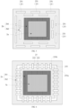
- the grooves 25 also surround the periphery of the light-emitting area 2a. That is, the grooves 25 are disposed at all sides of the light-emitting area 2a.
- the encapsulation reliability at all sides of the light-emitting area 2a is enhanced, thereby further increasing the service life of the stretchable display panel 100 and improving the space utilization rate of the pixel island 2.
- the saved space can be allocated to the light-emitting area 2a or the connecting wire 3, which is beneficial to improving the service life and stretching rate of the stretchable display panel 100.
- the orthographic projection of the groove 25 on the substrate 1 is shaped as a closed ring. As such, the encapsulation reliability of the periphery of the light-emitting area 2a is uniformly improved, ensuring good encapsulation reliability of the encapsulating layer 24.
- the orthographic projection of the groove 25 on the substrate 1 can be shaped as a rectangular ring, a circular ring, a triangular ring, or the like.
- the groove 25 includes a plurality of first groove segments 251.
- the plurality of first groove segments 251 are spaced from each other and together surround the periphery of the light-emitting area 2a.
- the encapsulation reliability of the periphery of the light-emitting area 2a can be enhanced, while the occupied area of the groove 25 can be reduced, thereby reducing the cost of etching the groove 25.
- the plurality of first groove segments 251 uniformly surround the periphery of the light-emitting area 2a, so that the encapsulation reliability of the periphery of the light-emitting area 2a can be improved uniformly.
- each groove 25 includes a plurality of first groove segments 251.
- a gap exists between two adjacent first groove segments 251.
- the gap of one groove 25 is located corresponding to one first groove segment 251 of another groove 25.
- the first groove segments 251 of the two adjacent grooves 25 are disposed in a staggered manner, which not only reduces the occupied area of the grooves 25 but also further improves the encapsulation reliability of the encapsulating layer 24.
- the groove 25 includes a first main groove 252 and a plurality of first sub-grooves 253.
- An orthographic projection of the first main groove 252 on the substrate 1 is shaped as a closed ring.
- the first main groove 252 surrounds the periphery of the light-emitting area 2a.
- the plurality of first sub-grooves 253 are spaced from each other and together surround the periphery of the light-emitting area 2a.
- An orthographic projection of the first sub-grooves 253 on the substrate 1 overlaps with the orthographic projection of the first main groove 252 on the substrate 1.
- the contact area between the encapsulating layer 24 and the groove 25 is further increased, thereby enhancing the encapsulation reliability of the encapsulating layer 24.
- the first sub-groove 253 includes a first end 253a and a second end 253b opposite to the first end.
- the first end 253a is located at the side of the first main groove 252 adjacent to the light-emitting area 2a
- the second end 253b is located at the side of the first main groove 252 away from the light-emitting area 2a. That is, the first sub-grooves 253 intersect with the first main groove 252.
- the contact area between the encapsulating layer 24 and the groove 25 is further increased, thereby enhancing the encapsulation reliability of the encapsulating layer 24.
- the encapsulating layer 24 covers the first sub-grooves 253 and the first main groove 252, the first main groove 252 and the first sub-groove 253 form a latch structure.
- the latch structure can alleviate expansion of the peeling.
- the latch structure can block the crack extension. Therefore, the overall encapsulation reliability of the encapsulating layer 24 is enhanced, and the service life of the stretchable display panel 100 is increased.
- the dimension of the orthographic projection of the groove 25 on the substrate 1 along a first direction X is a first width W 1 .
- the distance between two adjacent grooves 25 is a first spacing L 1 .
- the first width W 1 is greater than or equal to the first spacing L 1 .
- the first direction X is perpendicular to the thickness direction of the substrate 1 and perpendicular to the length direction of the orthographic projection of the groove 25 on the substrate 1.
- the difficulty of etching the groove 25 can be reduced, and the adhesion stability between the encapsulating layer 24 and the groove 25 can be increased.
- the number of the grooves 25 in a limited space can be increased.
- the driving layer group 21 includes a main body portion 2111 and an edge portion 2112 connected to the main body portion 2111.
- the pixel-defining structure 22 and the light-emitting unit 23 are both disposed on the main body portion 2111.
- the pixel island further includes at least one protective structure 26 disposed on the edge portion 2112.
- the protective structure 26 includes at least one concave portion 26a.
- the encapsulating layer 24 further covers the surface of the concave portion 26a.
- the protective structure 26 is configured to mitigate the crack extension toward the main body portion 2111. Specifically, the protective structure 26 mitigates the extension of the cracks through the concave portion 26a.
- the concave portion 26a can mitigate the extending tendency of the crack toward the main body portion 2111; and on the other hand, the concave portion 26a can increase the contact area of the encapsulating layer 24, thereby enhancing the overall encapsulation reliability of the encapsulating layer 24, and further increasing the service life of the stretchable display panel 100.
- the size of the main body portion 2111 is greater than the size of the edge portion 2112. That is, the thickness of the main body portion 2111 is greater than the thickness of the edge portion 2112.
- the driving layer group 21 includes a base layer 211, and the base layer 211 is disposed on the substrate 1.
- Other film layers of the driving layer group 21, such as a blocking layer 217, a buffer layer 218, a gate electrode insulating layer 215, a capacitance insulating layer 216, an interlayer insulating layer 212, and a planarizing layer 213, are stacked on the base layer 211.
- the main body portion 2111 and the edge portion 2112 are belonged to the base layer 211.
- the edge of the base layer 211 is thinned to form the edge portion 2112, and the area of the base layer 211 that is not thinned forms the main body portion 2111.
- the encapsulating layer 24 at the edge portion 2112 of the pixel island 2 is easy to crack.
- the protective structure 26 can mitigate the extension of the cracks in the encapsulating layer 24 at the edge portion 2112 of the pixel island 2 toward a side surface of the main body portion 2111 and the light-emitting area 2a.
- the protective structure 26 can block and mitigate the crack extension, effectively protecting the encapsulating layer 24 on the side surface and upper surface of the pixel island 2, thereby enhancing the encapsulation reliability.
- the encapsulating layer 24 further covers a side surface of the pixel-defining structure 22 and a side surface of the main body portion 2111. Specifically, the encapsulating layer 24 extends along the upper surface of the pixel-defining structure 22 toward the edge portion 2112, and covers the side surface of the pixel-defining structure 22 and the side surface of the main body portion 2111 on its extending path. As such, the contact area of the encapsulating layer 24 is increased, thereby enhancing the encapsulation reliability of the encapsulating layer 24.
- the edge portion 2112 surrounds the periphery of the main body portion 2111, and the protective structure 26 also surrounds the periphery of the main body portion 2111.
- the encapsulation reliability of all sides of the light-emitting area 2a can be enhanced, thereby further improving the protection effect of the protective structure 26.
- a plurality of protective structures 26 spaced from each other are disposed on the edge portion 2112.
- the encapsulating layer 24 covers the concave portion 26a of each protective structure 26.
- one protective structure 26 surrounds the periphery of the main body portion 2111, and another protective structure 26 surrounds the periphery of the one protective structure 26.
- the two protective structures 26 coaxially surround the periphery of the light-emitting area 2a, which is conducive to forming multiple layers of protective structures 26 that are coaxially arranged around the periphery of the light-emitting area 2a, thereby further enhancing the encapsulation reliability and the protection effect.
- the protective structure 26 includes a plurality of sub-structures 26b, and the plurality of sub-structures 26b are spaced from each other and together surround the periphery of the main body portion 2111.
- the encapsulation reliability of the periphery of the light-emitting area 2a can be enhanced, while the occupied area of the protective structure 26 can be reduced.
- the plurality of sub-structures 26b uniformly surround the periphery of the light-emitting area 2a, so that the encapsulation reliability of the periphery of the light-emitting area 2a can be uniformly enhanced.
- each protective structure 26 includes a plurality of sub-structures 26b.
- a gap exists between two adjacent sub-structures 26b.
- the gap of one protective structure 26 is located corresponding to one sub-structure 26b of another protective structure 26.
- the sub-structures 26b of the two adjacent protective structures 26 are disposed in a staggered manner, which not only reduces the occupied area of the protective structure 26, but also further enhances the encapsulation reliability of the encapsulating layer 24.
- the dimension of the orthographic projection of the protective structure 26 on the substrate 1 along the first direction X is a second width W 2 .
- the distance between two adjacent protective structures 26 is a second spacing L 2 .
- the second width W 2 is greater than or equal to the second spacing L 2 .
- the first direction X is perpendicular to the thickness direction of the substrate 1 and perpendicular to the length direction of the protective structure 26.
- the adhesion stability between the encapsulating layer 24 and the protective structure 26 can be increased, and the space occupied by the protective structure 26 can be reduced.
- the encapsulating layer 24 can be deposited between two adjacent protective structures 26, ensuring good structural contact between the encapsulating layer 24 and the two protective structures 26, thereby enhancing the encapsulation reliability of the encapsulating layer 24.
- the concave portion 26a is located on at least one side of the protective structure 26 along the first direction X.
- the protective structure 26 includes a concave portion 26a at one side along the first direction X.
- the cross section of the protective structure 26 has a "C" shape.
- the protective structure 26 includes a plurality of concave portions 26a, and the encapsulating layer 24 covers surfaces of the plurality of concave portions 26a.
- the protective structure 26 can more effectively block the crack expansion; and on the other hand, the contact area between the encapsulating layer 24 and the protective structure 26 can be increased, thereby enhancing the overall encapsulation reliability of the encapsulating layer 24, and further increasing the service life of the stretchable display panel 100.
- the protective structure 26 includes two concave portions 26a, and openings of the two concave portions 26a are opposite to each other.
- the encapsulating layer 24 completely covers the two concave portions 26a of the protective structure 26, on the one hand, when the cracks in the encapsulating layer 24 extend, they extends along relatively tortuous paths, increasing the difficulty of crack extension, thereby further blocking the crack expansion; on the other hand, when peeling occurs in the encapsulating layer 24, the two concave portions 26a of the protective structure 26 form a latch structure to lock the encapsulating layer 24, thereby reducing the peeling tendency of the encapsulating layer 24.
- the protective structure 26 includes a first sub-portion 261 and a second sub-portion 262 which are sequentially stacked on the edge portion 2112. Two opposite ends of the second sub-portion 262 along the first direction X respectively protrude from the side surfaces of the first sub-portion 261.
- the first direction X is perpendicular to the thickness direction of the substrate 1.
- the first sub-portion 261, the protruding portion of the second sub-portion 262, and the edge portion 2112 together define the concave portion 26a.
- the protective structure 26 can have a simple structure.
- the cross section of the protective structure 26 has a "T" shape.
- the protective structure 26 includes a third sub-portion 263, a first sub-portion 261, and a second sub-portion 262 which are sequentially stacked on the edge portion 2112. Two opposite ends of the third sub-portion 263 along the first direction X respectively protrude from the side surfaces of the first sub-portion 261. Two opposite ends of the second sub-portion 262 along the first direction X respectively protrude from the side surfaces of the first sub-portion 261.
- the first direction X is perpendicular to the thickness direction of the substrate 1.
- the protruding portion of the third sub-portion 263, the first sub-portion 261, and the protruding portion of the second sub-portion 262 together define the concave portion 26a. As such, the contact area between the protective structure 26 and the encapsulating layer 24 is increased, which is conducive to improving the adhesion stability between the protective structure 26 and the encapsulating layer 24.
- the cross section of the protective structure 26 has an "I" shape.
- the third sub-portion 263 and the second sub-portion 262 are made of a same material.
- the third sub-portion 263 and the first section 261 are made of different materials.
- the material of the third sub-portion 263 includes titanium, and the material of the first sub-portion 261 includes aluminum.
- the protective structure 26 is a structure composed of three metal layers of titanium-aluminum-titanium. As such, the protective structure 26 can be formed by side-etching a metal layer stack. It can be understood that the protective structure 26 can be alternatively a metal layer stack made of other materials.
- an embodiment of the present application provides another stretchable display panel 100.
- the stretchable display panel 100 includes a substrate 1 and a plurality of pixel islands 2.
- the plurality of pixel islands 2 are disposed on the substrate 1 and are spaced from each other.
- the pixel island 2 has a light-emitting area 2a and a non-light-emitting area 2b adjacent to the light-emitting area 2a.
- the substrate 1 is a flexible substrate 1 and is stretchable.
- the pixel island 2 includes a driving layer group 21, a light-emitting unit 23, an encapsulation auxiliary structure 27, and an encapsulating layer 24.
- the driving layer group 21 is disposed on the substrate 1.
- the light-emitting unit 23 is disposed on the driving layer group 21 and is located in the light-emitting area 2a.
- the encapsulation auxiliary structure 27 is disposed on the driving layer group 21 and is located in the non-light-emitting area 2b.
- At least one slot 271 is disposed at a side of the encapsulation auxiliary structure 27 away from the driving layer group 21.
- the encapsulation auxiliary structure 27 includes an inorganic material.
- the encapsulating layer 24 covers a surface of the light-emitting unit 23 away from the substrate 1 and a surface of the slot 271.
- the encapsulating layer 24 is an inorganic encapsulating film layer.
- the encapsulating layer 24 extends from the surface of the light-emitting unit 23 toward the non-light-emitting area 2b, and covers the surface of the encapsulation auxiliary structure 27 and the surface of the slot 271.
- the slot 271 is an inorganic slot. That is, the surface of the slot 271 is made of an inorganic material.
- the non-light-emitting area 2b includes a transitional area 2b1 and an encapsulation area 2b2.
- the transitional area 2b 1 is located between the encapsulation area 2b2 and the light-emitting area 2a.
- the encapsulation auxiliary structure 27 can be disposed in the encapsulation area 2b2.
- the non-light-emitting area 2b surrounds a periphery of the light-emitting area 2a.
- the encapsulation auxiliary structure 27 is disposed on the driving layer group 21, the slot 271 is disposed in the encapsulation auxiliary structure 27, and the encapsulating layer 24 extends to cover the surface of the slot 27.
- the slot 271 can mitigate the extending tendency of cracks toward the light-emitting area 2a.
- the slot 271 can increase the contact area of the encapsulating layer 24, improving the encapsulation performance of the encapsulating layer 24.
- the encapsulating layer 24 is in direct contact with the inorganic slot 271, and that is, an inorganic film layer is in contact with another inorganic film layer, thereby improving the film adhesion of the encapsulating layer 24, which further improves the encapsulation performance of the encapsulating layer 24, thereby enhancing the overall encapsulation reliability of the encapsulating layer 24, and increasing the service life of the stretchable display panel 100.
- a plurality of slots 271 are spaced from each other and disposed at the side of the encapsulation auxiliary structure 27 away from the driving layer group 21.
- the encapsulating layer 24 covers the surfaces of the plurality of slots 271.
- the slots 271 can effectively block the crack expansion and further mitigate the extending tendency of the cracks toward the light-emitting area 2a.
- the contact area between the encapsulating layer 24 and the inorganic surfaces of the slots 271 can be increased, which can further improve the film adhesion of the encapsulating layer 24, thereby enhancing the overall encapsulation reliability of the encapsulating layer 24, and increasing the service life of the stretchable display panel 100.
- the number of the slots 271 or the number of slot groups is not less than 5, so that the encapsulating layer 24 can have further enhanced encapsulation reliability.
- the inventors have discovered through research that by arranging the slot 271 in such a way described in the embodiments of the present application, such as arranging five groups of slots 271, the width of the non-light-emitting area 2b 1 can be reduced by about 14 ⁇ m to about 24 ⁇ m on the premise of achieving the same encapsulation effect when compared with the structure without the slot 271 in the related art, thereby being conducive to reducing the width of the encapsulation frame of the pixel island 2.
- an orthographic projection of the encapsulating layer 24 on the substrate 1 covers an orthographic projection of the slot 271 on the substrate 1. That is, the encapsulating layer 24 completely covers the entire surfaces of the slots 271. As such, the encapsulating layer 24 can have a relatively large contact area, further improving the encapsulation reliability of the encapsulating layer 24.
- the layout of the slots 271 in the embodiments of the present application can refer to the layout of the grooves 25 shown in FIG. 3 to FIG. 6 .
- the encapsulation auxiliary structure 27 surrounds the periphery of the light-emitting area 2a, and the slots 271 also surround the periphery of the light-emitting area 2a. That is, the slots 271 are disposed at all sides of the light-emitting area 2a. As such, the encapsulation reliability at all sides of the light-emitting area 2a is enhanced, thereby further increasing the service life of the stretchable display panel 100.
- the orthographic projection of the slot 271 on the substrate 1 is shaped as a closed ring. As such, the encapsulation reliability of the periphery of the light-emitting area 2a can be uniformly improved, ensuring good encapsulation reliability of the encapsulating layer 24.
- the orthographic projection of the slot 271 on the substrate 1 can be shaped as a rectangular ring, a circular ring, a triangular ring, or the like.
- the slot 271 includes a plurality of second slot segments, and the plurality of second slot segments are spaced from each other and together surround the periphery of the light-emitting area 2a.
- the encapsulation reliability of the periphery of the light-emitting area 2a can be enhanced, while the occupied area of the slot 271 can be reduced, thereby reducing the cost of etching the slot 271.
- the plurality of second slot segments uniformly surround the periphery of the light-emitting area 2a, so that the encapsulation reliability of the periphery of the light-emitting area 2a can be uniformly improved.
- each slot 271 in two adjacent slots 271, includes a plurality of second slot segments. In the same slot 271, a gap exists between two adjacent second slot segments. In the two adjacent slots 271, the gap of one slot 271 is located corresponding to one second slot segment of another slot 271.
- the second slot segments of the two adjacent slots 271 are disposed in a staggered manner, which not only reduces the occupied area of the slot 271 but also further improves the encapsulation reliability of the encapsulating layer 24.
- the slot 271 includes a second main slot and a plurality of second sub-slot.
- An orthographic projection of the second main slot on the substrate 1 is shaped as a closed ring.
- the second main slot surrounds the periphery of the light-emitting area 2a.
- the plurality of second sub-slots are spaced from each other and together surround the periphery of the light-emitting area 2a.
- An orthographic projection of the second sub-slots on the substrate 1 overlaps with the orthographic projection of the second main slot on the substrate 1.
- the contact area between the encapsulating layer 24 and the slot 271 is further increased, thereby enhancing the encapsulation reliability of the encapsulating layer 24.
- the second sub-slot includes a third end and a fourth end opposite to the third end.
- the third end is located at the side of the second main slot adjacent to the light-emitting area 2a
- the fourth end is located at the side of the second main slot away from the light-emitting area 2b. That is, the second sub-slots intersect with the second main slot.
- the contact area between the encapsulating layer 24 and the slot 271 is further increased, thereby enhancing the encapsulation reliability of the encapsulating layer 24.
- the encapsulating layer 24 covers the second sub-slots and the second main slot, the second main slot and the second sub-slot form a latch structure.
- the latch structure can alleviate expansion of the peeling.
- the latch structure can block the crack extension.
- the dimension of the orthographic projection of the slot 271 on the substrate 1 along a first direction X is a third width W 3 .
- the distance between two adjacent slots 271 is a third spacing L 3 .
- the third width W 3 is greater than or equal to the third spacing L 3 .
- the first direction X is perpendicular to the thickness direction of the substrate 1, and perpendicular to the length direction of the orthographic projection of the slot 271 on the substrate 1.
- the difficulty of etching the slot 271 can be reduced, and the adhesion stability between the encapsulating layer 24 and the slot 271 can be increased.
- the number of the slots 271 in a limited space can be increased.
- the encapsulation auxiliary structure 27 includes at least one protrusion portion 272 disposed at a side adjacent to the driving layer group 21, and the driving layer group 21 includes at least one recess portion 2131 disposed at a side adjacent to the encapsulation auxiliary structure 27.
- the at least one protrusion portion 272 mates with the at least one recess portion 2131.
- the contact area between the encapsulation auxiliary structure 27 and the driving layer group 21 can be increased, which increases the bonding force between the encapsulation auxiliary structure 27 to the driving layer group 21, thereby improving the stability of the encapsulation auxiliary structure 27.
- the encapsulation auxiliary structure 27 includes a plurality of protrusion portions 272 spaced from each other and disposed at a side adjacent to the driving layer group 21, and the driving layer group 21 includes a plurality of recess portions 2131 disposed at a side adjacent to the encapsulation auxiliary structure 27.
- the plurality of protrusion portions 272 mate with the plurality of recess portions 2131 in a one-to-one correspondence.
- the contact area between the encapsulation auxiliary structure 27 and the driving layer group 21 can be further increased, which increases the bonding force between the encapsulation auxiliary structure 27 to the driving layer group 21, thereby improving the stability of the encapsulation auxiliary structure 27.
- a plurality of slots 271 are spaced from each other and disposed in the encapsulation auxiliary structure 27.
- An orthographic projection of the slot 271 on the driving layer group 21 overlaps with an orthographic projection of the protrusion portion 272 on the driving layer group 21. That is, the orthographic projection of the slot 271 on the driving layer group 21 falls within the orthographic projection of the protrusion portion 272 on the driving layer group 21. In other words, the position of the slot 271 is in alignment with the position of the protrusion portion 272.
- the orthographic projections of two slots 271 on the driving layer group 21 both fall within the orthographic projection of one protrusion portion 272 on the driving layer group 21.
- the slot 271 can be relatively deep, thereby increasing the contact area between the encapsulating layer 24 and the slot 271; on the other hand, the thickness of the encapsulation auxiliary structure 27 (i.e., the size of the encapsulation auxiliary structure 27 along the thickness direction of the substrate 1) at various positions can be increased, ensuring relatively high structural strength of the encapsulation auxiliary structure 27, so that the encapsulation auxiliary structure 27 is less likely to break.
- the plurality of slots 271 and the plurality of protrusion portions 272 are in a one-to-one correspondence.
- An orthographic projection of each slot 271 on the driving layer group 21 overlaps with an orthographic projection of the corresponding protrusion portion 272 on the driving layer group 21. That is, the slots 271 and the protrusion portions 272 are opposite to each other in a one-to-one correspondence at both sides of the encapsulation auxiliary structure 27.
- the thickness of the encapsulation auxiliary structure 27 i.e., the size of the encapsulation auxiliary structure 27 along the thickness direction of the substrate 1 at various positions can be increased, ensuring relatively high structural strength of the encapsulation auxiliary structure 27, so that the encapsulation auxiliary structure 27 is less likely to break.
- the driving layer group 21 includes a planarizing layer 213.
- the recess portion 2131 is disposed on a surface of the planarizing layer 213 away from the substrate 1.
- the pixel island 2 further includes a pixel-defining structure 22.
- the pixel-defining structure 22 is disposed on the surface of the planarizing layer 213 away from the substrate 1.
- the pixel-defining structure 22 defines a pixel opening located in the light-emitting area 2a.
- the light-emitting unit 23 is disposed in the pixel opening.
- the size of the recess portion 2131 is Hi, and the size of the planarizing layer 213 is H 2 .
- H 1 and H 2 satisfy a relationship of H 1 ⁇ 0.5H 2 .
- planarizing layer 213 located directly below the recess portion 2131 can be relatively thick, ensuring the structural strength of the planarizing layer 213, so that the planarizing layer 213 is less likely to break.
- a surface of the encapsulation auxiliary structure 27 adjacent to the driving layer group 21 is a flat surface. As such, the manufacturing difficulty of the encapsulation auxiliary structure 27 can be reduced.
- the stretchable display panel 100 includes a pixel-defining structure 22.
- the pixel-defining structure 22 is disposed on the driving layer group 21.
- the pixel-defining structure 22 defines a pixel opening located in the light-emitting area 2a.
- the light-emitting unit 23 is disposed in the pixel opening.
- a surface of the pixel-defining structure 22 adjacent to the driving layer group 21 is flush with the surface of the encapsulation auxiliary structure 27 adjacent to the driving layer group 21.
- the pixel-defining structure 22 and the encapsulation auxiliary structure 27 can be formed on the same surface of the same film layer, avoiding adverse effect of the encapsulation auxiliary structure 27 on the layout of the connecting lines and the layout of the film layers in the driving layer group 21.
- the driving layer group 21 includes a planarizing layer 213.
- the pixel-defining structure 22 and the encapsulation auxiliary structure 27 are disposed on the surface of the planarizing layer 213 away from the substrate 1.
- the pixel-defining structure 22 is adjacent to the encapsulation auxiliary structure 27, which is beneficial for the encapsulating layer 24 extends from the surface of the pixel-defining structure 22 to the surface of the encapsulation auxiliary structure 27, thereby forming a continuous film layer structure.
- the driving layer group 21 includes a main body portion 2111 and an edge portion 2112 connected to the main body portion 2111.
- the light-emitting unit 23 is disposed on the main body portion 2111.
- the pixel island 2 further includes at least one protective structure 26 disposed on the edge portion 2112.
- the protective structure 26 includes at least one concave portion 26a.
- the encapsulating layer 24 further covers a surface of the concave portion 26a.
- the stretchable display panel 100 includes a pixel-defining structure 22.
- the pixel-defining structure 22 is disposed on the main body portion 2111.
- the pixel-defining structure 22 defines a pixel opening located in the light-emitting area 2a.
- the light-emitting unit 23 is disposed in the pixel opening.
- the encapsulating layer 24 further covers a side surface of the pixel-defining structure 22 and a side surface of the main body portion 2111. Specifically, the encapsulating layer 24 extends along the upper surface of the pixel-defining structure 22 toward the edge portion 2112, and covers the side surface of the pixel-defining structure 22 and the side surface of the main body portion 2111 on its extending path. As such, the contact area of the encapsulating layer 24 is increased, thereby enhancing the encapsulation reliability of the encapsulating layer 24.
- the protective structure 26 includes two concave portions 26a, and openings of the two concave portions 26a are opposite to each other.
- the encapsulating layer 24 completely covers the two concave portions 26a of the protective structure 26, on the one hand, when the cracks in the encapsulating layer 24 extend, they extends along relatively tortuous paths, increasing the difficulty of crack extension, thereby further blocking the crack expansion; on the other hand, when peeling occurs in the encapsulating layer 24, the two concave portions 26a of the protective structure 26 form a latch structure to lock the encapsulating layer 24, thereby reducing the peeling tendency of the encapsulating layer 24.
- the stretchable display panel 100 further includes a connecting wire 3.
- Adjacent pixel islands 2 are connected through the connecting wire 3.
- the driving layer group 21 includes a connecting line 214, and the connecting line 214 is electrically connected to the connecting wire 3.
- the driving layer group 21 includes a pixel driving circuit.
- One end of the connecting line 214 is connected to the pixel driving circuit, and another end of the connecting line 214 is connected to the connecting wire 3. That is, the pixel driving circuits of adjacent pixel islands 2 are connected through the connecting wire 3 and the connecting lines 214.
- the connecting line 214 is disposed between the interlayer insulating layer 212 and the planarizing layer 213.
- a third metal layer can be disposed between the interlayer insulating layer 212 and the planarizing layer 213.
- the third metal layer includes some leading wires of the pixel driving circuit.
- the third metal layer further includes the connecting line 214, thereby simplifying the manufacturing processes of the stretchable display panel 100 and reducing the manufacturing cost.
- the display panel provided by the second aspect can reduce the adverse effect on the connecting line 214 in the driving layer group 21 caused by the layout of the slots 271, thereby reducing the manufacturing cost of the display panel.
- an embodiment of the present application provides yet another stretchable display panel 100.
- the stretchable display panel 100 includes a substrate 1 and a plurality of pixel islands 2.
- the plurality of pixel islands 2 are disposed on the substrate 1 and spaced from each other.
- the pixel island 2 has a light-emitting area 2a and a non-light-emitting area 2b adjacent to the light-emitting area 2a.
- the substrate 1 is a flexible substrate 1 and is stretchable.
- the pixel island 2 includes a driving layer group 21, a pixel-defining structure 22, a light-emitting unit 23, and an encapsulating layer 24.
- the driving layer group 21 is disposed on the substrate 1.
- the driving layer group 21 includes a main body portion 2111 and an edge portion 2112 connected to the main body portion 2111.
- the light-emitting unit 23 is disposed on the main body portion 2111.
- the pixel island further includes at least one protective structure 26 disposed on the edge portion 2112.
- the protective structure 26 includes at least one concave portion 26a.
- the encapsulating layer 24 covers a surface of the light-emitting unit 23 away from the substrate 1 and a surface of the concave portion 26a.
- the encapsulating layer 24 is an inorganic encapsulating layer film layer.
- the encapsulating layer 24 extends from the surface of the light-emitting unit 23 toward the edge portion 2112, and covers the surface of the protective structure 26 and the surface of the concave portion 26a.
- the protective structure 26 is configured to mitigate the crack extension toward the main body portion 2111. Specifically, the protective structure 26 mitigates the extension of the cracks through the concave portion 26a.
- the protective structure 26 is disposed on the edge portion 2112 and includes the concave portion 26a, and the encapsulating layer 24 extends to and cover the surface of the concave portion 26a.
- the concave portion 26a can mitigate the extending tendency of the cracks toward the main body portion 2111; and on the other hand, the concave portion 26a can increase the contact area of the encapsulating layer 24, thereby enhancing the overall encapsulation reliability of the encapsulating layer 24, and further increasing the service life of the stretchable display panel 100.
- the driving layer group 21 includes a base layer 211, and the driving layer group 21 is disposed on the substrate 1 through the base layer 211. In another embodiment, the driving layer group 21 does not include the base layer 211. That is, the driving layer group 21 is directly disposed on the substrate 1.
- the substrate 1 can includes a stretching area and a pixel area. The driving layer group 21 is located in the pixel area. When the display panel is stretched, the stretching area is extended, and the pixel area is not extendable.
- the material of the protective structure 26 can be an inorganic material, so as to improve the adhesion between the encapsulating layer 24 and the protective structure 26, thereby enhancing the encapsulation reliability.
- the driving layer group 21 includes a base layer 211 and a functional layer group disposed on the base layer 211.
- the base layer includes the main body portion 2111 and the edge portion 2112. As such, after the formation of the base layer 211, the edge of the base layer 211 is thinned to form the edge portion 2112, and the area of the base layer 211 that is not thinned forms the main body portion 2111.
- the encapsulating layer 24 further covers a side surface of the functional layer group. That is, the encapsulating layer 24 extends toward the edge portion 2112 and covers the side surface of the functional layer group on its extending path. As such, the contact area of the encapsulating layer 24 can be increased, thereby enhancing the encapsulation reliability of the encapsulating layer 24.
- the functional layer group includes a blocking layer 217 and a buffer layer 218 which are stacked one on another.
- the blocking layer 217 is located between the base layer 211 and the buffer layer 218.
- the encapsulating layer 24 further covers side surfaces of the blocking layer 217 and the buffer layer 218. That is, the encapsulating layer 24 extends toward the edge portion 2112, and covers the side surfaces of the blocking layer 217 and the buffer layer 218 on its extending path. As such, the contact area of the encapsulating layer 24 can be increased, thereby enhancing the encapsulation reliability of the encapsulating layer 24.
- the functional layer group further includes a gate electrode insulating layer 215 disposed at a side of the buffer layer 218 away from the base layer 211.
- the encapsulating layer 24 further covers a side surface of the gate electrode insulating layer 215. That is, the encapsulating layer 24 extends toward the edge portion 2112, and covers the side surface of the gate electrode insulating layer 215 on its extending path. As such, the contact area of the encapsulating layer 24 can be increased, thereby enhancing the encapsulation reliability of the encapsulating layer 24.
- the functional layer group further includes a capacitance insulating layer 216 disposed at a side of the gate electrode insulating layer 215 away from the base layer 211.
- the encapsulating layer 24 further covers a side surface of the capacitance insulating layer 216. That is, the encapsulating layer 24 extends toward the edge portion 2112, and covers the side surface of the capacitance insulating layer 216 on its extending path. As such, the contact area of the encapsulating layer 24 can be increased, thereby enhancing the encapsulation reliability of the encapsulating layer 24.
- the functional layer group further includes an interlayer insulating layer 212 disposed at a side of the capacitance insulating layer 216 away from the base layer 211.
- the encapsulating layer 24 further covers a side surface of the interlayer insulating layer 212. That is, the encapsulating layer 24 extends toward the edge portion 2112, and covers the side surface of the interlayer insulating layer 212 on its extending path. As such, the contact area of the encapsulating layer 24 can be increased, thereby enhancing the encapsulation reliability of the encapsulating layer 24.
- the functional layer group further includes a planarizing layer 213 disposed at a side of the interlayer insulating layer 212 away from the base layer 211.
- the encapsulating layer 24 further covers a side surface of the planarizing layer 213. That is, the encapsulating layer 24 extends toward the edge portion 2112, and covers the side surface of the planarizing layer 213 on its extending path. As such, the contact area of the encapsulating layer 24 can be increased, thereby enhancing the encapsulation reliability of the encapsulating layer 24.
- stretchable display panel 100 provided in the third aspect can include other features of the stretchable display panel 100 provided in the first aspect and/or other features of the stretchable display panel 100 provided in the second aspect, which will not be repeated in the embodiments of the present application.
- an embodiment of the present application provides a display device, including the stretchable display panel in any one of the embodiments of the first aspect, the second aspect, or the third aspect.
- the display device can be a smart wearable display device, a laptop computer, a mobile phone, a wireless device, a personal digital assistant (PDA), a handheld or portable computer, a GPS receiver or navigator, a camera, an MP4 video player, a camcorder, a game console, a watch, a clock, a calculator, a television monitor, a flat panel display, a computer monitor, a car display (e.g., an odometer display, etc.), a navigator, a cockpit controller and/or display, a display of a camera view (e.g., a display of a rearview camera in a vehicle), an electronic photo, an electronic billboard or sign, a projector, etc.
- a camera view e.g., a display of a rearview camera in a vehicle
- an electronic photo e.g., an electronic billboard or sign, a projector, etc.
- the extending tendency of cracks toward the light-emitting unit can be mitigated; on the other hand, the contact area of the encapsulating layer can be increased, thereby enhancing the overall encapsulation reliability and further increasing the service life of the display device.
Landscapes
- Engineering & Computer Science (AREA)
- Microelectronics & Electronic Packaging (AREA)
- Chemical & Material Sciences (AREA)
- Inorganic Chemistry (AREA)
- Devices For Indicating Variable Information By Combining Individual Elements (AREA)
- Electroluminescent Light Sources (AREA)
- Illuminated Signs And Luminous Advertising (AREA)
- Measuring Pulse, Heart Rate, Blood Pressure Or Blood Flow (AREA)
Applications Claiming Priority (1)
| Application Number | Priority Date | Filing Date | Title |
|---|---|---|---|
| CN202311199578.XA CN119654001A (zh) | 2023-09-15 | 2023-09-15 | 可拉伸显示面板及显示装置 |
Publications (2)
| Publication Number | Publication Date |
|---|---|
| EP4460170A2 true EP4460170A2 (de) | 2024-11-06 |
| EP4460170A3 EP4460170A3 (de) | 2025-03-26 |
Family
ID=92792211
Family Applications (1)
| Application Number | Title | Priority Date | Filing Date |
|---|---|---|---|
| EP24200020.6A Pending EP4460170A3 (de) | 2023-09-15 | 2024-09-12 | Dehnbare anzeigetafel und anzeigevorrichtung |
Country Status (4)
| Country | Link |
|---|---|
| US (1) | US20250008820A1 (de) |
| EP (1) | EP4460170A3 (de) |
| JP (1) | JP7752224B2 (de) |
| CN (1) | CN119654001A (de) |
Family Cites Families (4)
| Publication number | Priority date | Publication date | Assignee | Title |
|---|---|---|---|---|
| KR102814723B1 (ko) * | 2019-06-21 | 2025-05-30 | 삼성디스플레이 주식회사 | 표시 장치 |
| CN110416266B (zh) * | 2019-07-29 | 2022-07-22 | 京东方科技集团股份有限公司 | 显示基板及包含其的显示面板 |
| CN111370454B (zh) * | 2020-03-18 | 2023-12-29 | 京东方科技集团股份有限公司 | 可拉伸显示器件的制造方法及可拉伸显示器件 |
| CN116210363A (zh) * | 2021-09-28 | 2023-06-02 | 京东方科技集团股份有限公司 | 显示基板及其制备方法、显示装置 |
-
2023
- 2023-09-15 CN CN202311199578.XA patent/CN119654001A/zh active Pending
-
2024
- 2024-09-11 JP JP2024157354A patent/JP7752224B2/ja active Active
- 2024-09-12 US US18/883,097 patent/US20250008820A1/en active Pending
- 2024-09-12 EP EP24200020.6A patent/EP4460170A3/de active Pending
Also Published As
| Publication number | Publication date |
|---|---|
| CN119654001A (zh) | 2025-03-18 |
| US20250008820A1 (en) | 2025-01-02 |
| KR20240141671A (ko) | 2024-09-27 |
| JP2024169453A (ja) | 2024-12-05 |
| JP7752224B2 (ja) | 2025-10-09 |
| EP4460170A3 (de) | 2025-03-26 |
Similar Documents
| Publication | Publication Date | Title |
|---|---|---|
| US11871606B2 (en) | Display substrate and display device | |
| CN110165071B (zh) | 一种有机发光显示面板及有机发光显示装置 | |
| US11107875B2 (en) | Display panel, fabrication and driving method thereof, and display device | |
| CN119907415B (zh) | 显示面板和显示装置 | |
| CN115274790B (zh) | 显示面板及其制作方法 | |
| CN119053200A (zh) | 显示面板、显示面板的制备方法及显示装置 | |
| CN117156902A (zh) | 显示面板及其制作方法、显示装置 | |
| US11355730B2 (en) | Light emitting panel and display device | |
| CN116390573A (zh) | 显示面板及显示装置 | |
| CN119907416A (zh) | 显示面板、显示装置和显示面板的制备方法 | |
| CN118890923A (zh) | 显示面板及显示装置 | |
| CN118139472A (zh) | 显示面板、显示面板的制备方法及显示装置 | |
| CN119136583A (zh) | 显示面板和显示装置 | |
| CN118660573A (zh) | 显示面板及显示装置 | |
| EP4460170A2 (de) | Dehnbare anzeigetafel und anzeigevorrichtung | |
| US20250072229A1 (en) | Display panel and method for manufacturing the same | |
| CN114335093A (zh) | 柔性显示面板及其制作方法以及显示装置 | |
| KR102955141B1 (ko) | 스트레처블 디스플레이 패널 및 디스플레이 장치 | |
| US12256623B2 (en) | OLED display panel and electronic device with improved encapsulation effect | |
| CN223987346U (zh) | 显示面板和显示装置 | |
| US20250176393A1 (en) | Display panel and display device | |
| US20250133881A1 (en) | Display panel and display device | |
| US20250072244A1 (en) | Display panel and display device | |
| CN120112091B (zh) | 显示面板和显示装置 | |
| US20250126939A1 (en) | Display apparatus and method of manufacturing the same |
Legal Events
| Date | Code | Title | Description |
|---|---|---|---|
| PUAI | Public reference made under article 153(3) epc to a published international application that has entered the european phase |
Free format text: ORIGINAL CODE: 0009012 |
|
| STAA | Information on the status of an ep patent application or granted ep patent |
Free format text: STATUS: REQUEST FOR EXAMINATION WAS MADE |
|
| 17P | Request for examination filed |
Effective date: 20240912 |
|
| AK | Designated contracting states |
Kind code of ref document: A2 Designated state(s): AL AT BE BG CH CY CZ DE DK EE ES FI FR GB GR HR HU IE IS IT LI LT LU LV MC ME MK MT NL NO PL PT RO RS SE SI SK SM TR |
|
| PUAL | Search report despatched |
Free format text: ORIGINAL CODE: 0009013 |
|
| AK | Designated contracting states |
Kind code of ref document: A3 Designated state(s): AL AT BE BG CH CY CZ DE DK EE ES FI FR GB GR HR HU IE IS IT LI LT LU LV MC ME MK MT NL NO PL PT RO RS SE SI SK SM TR |
|
| RIC1 | Information provided on ipc code assigned before grant |
Ipc: H10K 77/10 20230101ALI20250219BHEP Ipc: H10K 59/122 20230101AFI20250219BHEP |