EP4459768A1 - Wiederaufladbares batteriemodul - Google Patents
Wiederaufladbares batteriemodul Download PDFInfo
- Publication number
- EP4459768A1 EP4459768A1 EP22916696.2A EP22916696A EP4459768A1 EP 4459768 A1 EP4459768 A1 EP 4459768A1 EP 22916696 A EP22916696 A EP 22916696A EP 4459768 A1 EP4459768 A1 EP 4459768A1
- Authority
- EP
- European Patent Office
- Prior art keywords
- unit cells
- rechargeable battery
- battery module
- side plate
- protrusion
- Prior art date
- Legal status (The legal status is an assumption and is not a legal conclusion. Google has not performed a legal analysis and makes no representation as to the accuracy of the status listed.)
- Pending
Links
Images


Classifications
-
- H—ELECTRICITY
- H01—ELECTRIC ELEMENTS
- H01M—PROCESSES OR MEANS, e.g. BATTERIES, FOR THE DIRECT CONVERSION OF CHEMICAL ENERGY INTO ELECTRICAL ENERGY
- H01M50/00—Constructional details or processes of manufacture of the non-active parts of electrochemical cells other than fuel cells, e.g. hybrid cells
- H01M50/20—Mountings; Secondary casings or frames; Racks, modules or packs; Suspension devices; Shock absorbers; Transport or carrying devices; Holders
- H01M50/289—Mountings; Secondary casings or frames; Racks, modules or packs; Suspension devices; Shock absorbers; Transport or carrying devices; Holders characterised by spacing elements or positioning means within frames, racks or packs
- H01M50/291—Mountings; Secondary casings or frames; Racks, modules or packs; Suspension devices; Shock absorbers; Transport or carrying devices; Holders characterised by spacing elements or positioning means within frames, racks or packs characterised by their shape
-
- H—ELECTRICITY
- H01—ELECTRIC ELEMENTS
- H01M—PROCESSES OR MEANS, e.g. BATTERIES, FOR THE DIRECT CONVERSION OF CHEMICAL ENERGY INTO ELECTRICAL ENERGY
- H01M10/00—Secondary cells; Manufacture thereof
- H01M10/04—Construction or manufacture in general
- H01M10/0486—Frames for plates or membranes
-
- H—ELECTRICITY
- H01—ELECTRIC ELEMENTS
- H01M—PROCESSES OR MEANS, e.g. BATTERIES, FOR THE DIRECT CONVERSION OF CHEMICAL ENERGY INTO ELECTRICAL ENERGY
- H01M10/00—Secondary cells; Manufacture thereof
- H01M10/60—Heating or cooling; Temperature control
- H01M10/62—Heating or cooling; Temperature control specially adapted for specific applications
- H01M10/623—Portable devices, e.g. mobile telephones, cameras or pacemakers
-
- H—ELECTRICITY
- H01—ELECTRIC ELEMENTS
- H01M—PROCESSES OR MEANS, e.g. BATTERIES, FOR THE DIRECT CONVERSION OF CHEMICAL ENERGY INTO ELECTRICAL ENERGY
- H01M10/00—Secondary cells; Manufacture thereof
- H01M10/60—Heating or cooling; Temperature control
- H01M10/62—Heating or cooling; Temperature control specially adapted for specific applications
- H01M10/625—Vehicles
-
- H—ELECTRICITY
- H01—ELECTRIC ELEMENTS
- H01M—PROCESSES OR MEANS, e.g. BATTERIES, FOR THE DIRECT CONVERSION OF CHEMICAL ENERGY INTO ELECTRICAL ENERGY
- H01M50/00—Constructional details or processes of manufacture of the non-active parts of electrochemical cells other than fuel cells, e.g. hybrid cells
- H01M50/20—Mountings; Secondary casings or frames; Racks, modules or packs; Suspension devices; Shock absorbers; Transport or carrying devices; Holders
- H01M50/204—Racks, modules or packs for multiple batteries or multiple cells
- H01M50/207—Racks, modules or packs for multiple batteries or multiple cells characterised by their shape
- H01M50/209—Racks, modules or packs for multiple batteries or multiple cells characterised by their shape adapted for prismatic or rectangular cells
-
- H—ELECTRICITY
- H01—ELECTRIC ELEMENTS
- H01M—PROCESSES OR MEANS, e.g. BATTERIES, FOR THE DIRECT CONVERSION OF CHEMICAL ENERGY INTO ELECTRICAL ENERGY
- H01M50/00—Constructional details or processes of manufacture of the non-active parts of electrochemical cells other than fuel cells, e.g. hybrid cells
- H01M50/20—Mountings; Secondary casings or frames; Racks, modules or packs; Suspension devices; Shock absorbers; Transport or carrying devices; Holders
- H01M50/262—Mountings; Secondary casings or frames; Racks, modules or packs; Suspension devices; Shock absorbers; Transport or carrying devices; Holders with fastening means, e.g. locks
- H01M50/264—Mountings; Secondary casings or frames; Racks, modules or packs; Suspension devices; Shock absorbers; Transport or carrying devices; Holders with fastening means, e.g. locks for cells or batteries, e.g. straps, tie rods or peripheral frames
-
- H—ELECTRICITY
- H01—ELECTRIC ELEMENTS
- H01M—PROCESSES OR MEANS, e.g. BATTERIES, FOR THE DIRECT CONVERSION OF CHEMICAL ENERGY INTO ELECTRICAL ENERGY
- H01M50/00—Constructional details or processes of manufacture of the non-active parts of electrochemical cells other than fuel cells, e.g. hybrid cells
- H01M50/20—Mountings; Secondary casings or frames; Racks, modules or packs; Suspension devices; Shock absorbers; Transport or carrying devices; Holders
- H01M50/289—Mountings; Secondary casings or frames; Racks, modules or packs; Suspension devices; Shock absorbers; Transport or carrying devices; Holders characterised by spacing elements or positioning means within frames, racks or packs
- H01M50/293—Mountings; Secondary casings or frames; Racks, modules or packs; Suspension devices; Shock absorbers; Transport or carrying devices; Holders characterised by spacing elements or positioning means within frames, racks or packs characterised by the material
-
- H—ELECTRICITY
- H01—ELECTRIC ELEMENTS
- H01M—PROCESSES OR MEANS, e.g. BATTERIES, FOR THE DIRECT CONVERSION OF CHEMICAL ENERGY INTO ELECTRICAL ENERGY
- H01M50/00—Constructional details or processes of manufacture of the non-active parts of electrochemical cells other than fuel cells, e.g. hybrid cells
- H01M50/50—Current conducting connections for cells or batteries
- H01M50/572—Means for preventing undesired use or discharge
- H01M50/584—Means for preventing undesired use or discharge for preventing incorrect connections inside or outside the batteries
- H01M50/586—Means for preventing undesired use or discharge for preventing incorrect connections inside or outside the batteries inside the batteries, e.g. incorrect connections of electrodes
-
- H—ELECTRICITY
- H01—ELECTRIC ELEMENTS
- H01M—PROCESSES OR MEANS, e.g. BATTERIES, FOR THE DIRECT CONVERSION OF CHEMICAL ENERGY INTO ELECTRICAL ENERGY
- H01M2220/00—Batteries for particular applications
- H01M2220/20—Batteries in motive systems, e.g. vehicle, ship, plane
-
- H—ELECTRICITY
- H01—ELECTRIC ELEMENTS
- H01M—PROCESSES OR MEANS, e.g. BATTERIES, FOR THE DIRECT CONVERSION OF CHEMICAL ENERGY INTO ELECTRICAL ENERGY
- H01M2220/00—Batteries for particular applications
- H01M2220/30—Batteries in portable systems, e.g. mobile phone, laptop
-
- Y—GENERAL TAGGING OF NEW TECHNOLOGICAL DEVELOPMENTS; GENERAL TAGGING OF CROSS-SECTIONAL TECHNOLOGIES SPANNING OVER SEVERAL SECTIONS OF THE IPC; TECHNICAL SUBJECTS COVERED BY FORMER USPC CROSS-REFERENCE ART COLLECTIONS [XRACs] AND DIGESTS
- Y02—TECHNOLOGIES OR APPLICATIONS FOR MITIGATION OR ADAPTATION AGAINST CLIMATE CHANGE
- Y02E—REDUCTION OF GREENHOUSE GAS [GHG] EMISSIONS, RELATED TO ENERGY GENERATION, TRANSMISSION OR DISTRIBUTION
- Y02E60/00—Enabling technologies; Technologies with a potential or indirect contribution to GHG emissions mitigation
- Y02E60/10—Energy storage using batteries
Definitions
- the present disclosure relates to a rechargeable battery module.
- a rechargeable battery is a battery that is repeatedly charged and discharged, unlike a primary battery.
- Small capacity rechargeable batteries are used in small portable electronic devices such as mobile phones, tablet computers, and laptop computers, while large capacity rechargeable batteries may be used as a power source for driving motors in hybrid vehicles and electric vehicles.
- the rechargeable battery may be configured of unit cells, or as seen in the example used for motor driving, the rechargeable battery may be configured in a module state in which a plurality of unit cells are electrically connected, and in a pack state in which a plurality of these modules are connected again.
- a rechargeable battery module may be configured by arranging a plurality of unit cells in one direction. End plates may be disposed at both ends of the rechargeable battery module along the arrangement direction, and side plates may be disposed at both side surfaces thereof to fix a plurality of arranged unit cells.
- the end plate and the side plate are required to be designed to be suitable for fastening structures configuring the rechargeable battery module so that the plurality of unit cells may be combined with each other and firmly fixed.
- An aspect of the present disclosure attempts to provide a rechargeable battery module designed so that side plates may be firmly attached to side surfaces of a plurality of unit cells stacked.
- An embodiment provides a rechargeable battery module including: a plurality of unit cells arranged and stacked in a first direction and electrically connected to each other, an end plate disposed adjacent to an outermost unit cell of the plurality of unit cells and supporting the plurality of unit cells, and a side plate extending long along the first direction and supporting the plurality of unit cells.
- the side plate includes a main body fixed to the plurality of unit cells by an adhesive provided between the side plate and each of the plurality of unit cells; and a position fixing member integrally extending from a first surface of the main body facing the plurality of unit cells and positioned between the plurality of unit cells.
- the position fixing member is disposed in a space between the plurality of unit cells, and the adhesive is in close contact with the position fixing member within the space between the plurality of unit cells to be positioned within the space between the plurality of unit cells.
- the position fixing member may be configured as a protrusion by embossing.
- At least one or more of the protrusions may be disposed between neighboring unit cells among the plurality of unit cells.
- the adhesive may be in direct contact with neighboring unit cells among the plurality of unit cells.
- the unit cell When viewed in a second direction perpendicular to the first direction, the unit cell may be configured as a prismatic rechargeable battery of which corner portions are rounded, and the protrusion may be configured to have a shape in which a first curvature portion corresponding to a curvature of the corner portion is symmetrically disposed.
- a first interval which is an interval between a side surface of the unit cell and a main body of the side plate, may be the same as a second interval, which is an interval between the curvature portion of the corner portion of the unit cell and the first curvature portion of the protrusion.
- the number of the plurality of unit cells may be sixteen, and the protrusion may be respectively interposed between the plurality of unit cells.
- An insulating member may be respectively disposed between the plurality of unit cells.
- the insulating member may be installed in an insulating frame, and the insulating frame may include a frame main body on which the insulating member is supported, and a fixing portion extending from an end portion of the frame main body to be disposed in a space between the plurality of unit cells and fixed to the position fixing member by the adhesive.
- a first interval which is an interval between a side surface of the unit cell and a main body of the side plate, may be the same as a third interval, which is an interval between a curvature portion of the fixing portion and the first curvature portion of the protrusion.
- the position fixing member disposed on the side plate corresponding to between the unit cells may sufficiently push the adhesive into a space between the unit cells.
- the adhesive may fix the plurality of unit cells and the side plate while maintaining a uniform thickness between the plurality of unit cells and the side plate.
- the fixing structure described above may serve as an element that may increase the performance of the rechargeable battery module by strengthening the rigidity of the rechargeable battery module.
- the phrase “in a plan view” or “on a plane” means viewing a target portion from the top
- the phrase “in a cross-sectional view” or “on a cross-section” means viewing a cross-section formed by vertically cutting a target portion from the side.
- connection does not only mean when two or more elements are directly connected, but also when two or more elements are indirectly connected through other elements, and when they are physically connected or electrically connected, and further, it may be referred to by different names depending on a position or function, and may also be referred to as a case in which respective parts that are substantially integrated are linked to each other.
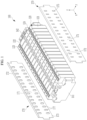
- FIG. 1 illustrates a partially exploded perspective view of a rechargeable battery module according to an embodiment
- FIG. 2 illustrates a perspective view of a rechargeable battery module according to an embodiment.
- a rechargeable battery module 100 includes a plurality of unit cells 120, end plates 141 and 142 disposed adjacent to and outside the outermost unit cell 120, and side plates 170 disposed to support side surfaces of the plurality of unit cells 120.
- the plurality of unit cells 120 may be arranged and stacked in a first direction (an x-axis direction in FIG. 1 ) and electrically and mechanically connected to each other.
- Each of the plurality of unit cells 120 may be formed of a prismatic rechargeable battery, and may be electrically connected through a bus bar (not shown).
- the unit cell 120 may include a case 121 in which an electrode assembly is embedded, a cap plate 122 coupled to an opening of the case 121, and a first electrode terminal 123 and a second electrode terminal 124 installed in the cap plate 122.
- the first electrode terminal 123 may be a negative electrode terminal
- the second electrode terminal 124 can be a positive electrode terminal.
- the case 121 may have a rectangular parallelepiped shape in which a side surface having a wide width and a side surface having a narrow width are disposed opposite to each other.
- the case 121 may have a rounded corner (see FIG. 3 ) at each corner when viewed in a second direction (z-axis direction of FIG. 1 ) perpendicular to the first direction (x).
- the present disclosure is not limited to the unit cell structure described above.
- the end plates 141 and 142 may support the plurality of unit cells 120 by pressing them in the first direction (x) while being in close contact with the outer surface of the outermost unit cell 120.
- the end plates 141 and 142 may be fixed to the outermost unit cell 120 by an adhesive.
- the side plate 170 includes a plate-shaped main body 171 extending long in the first direction (x), and may be disposed to face both side surfaces of the unit cell 120 to support the side surfaces of the plurality of unit cells 120, for example, a side surface having a narrow width of the case 121 of the unit cell 120.
- the main body 171 of the side plate 170 may partially protrude from both ends thereof in the first direction (x) to be connected to the end plates 141 and 142, and the upper end thereof may be bent inward to be fixed to the upper edge of the plurality of unit cells 120.
- a pair of side plates 170 may be provided, one on both side surfaces of the plurality of unit cells 120 having a narrow width.
- the rigidity of the battery module may be reinforced by fixing the side plate 170 to the unit cell 120 through a fixing member such as an adhesive. That is, the side plate 170 may be pressed and fixed to the side surfaces of the plurality of unit cells 120 while the adhesive is applied to the side surface having a narrow width of each of the plurality of unit cells 120 along the first direction (x).
- a fixing member such as an adhesive
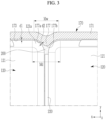
- the side plate 170 may be coupled to the plurality of unit cells 120 in the correct position by a position fixing member 175 integrally extending from a first surface 173 of the main body 171.
- the position fixing member 175 may be configured as a protrusion 177 by embossing.
- the protrusion 177 is disposed in the space between the plurality of unit cells 120, as shown in FIG. 3 .
- the protrusion 177 may be previously formed in the main body 171 of the side plate 170 according to the interval between the plurality of unit cells 120 aligned along the first direction (x).
- the protrusion 177 may be provided by embossing the main body 171 of the side plate 170 so that its center coincides with the center of the space between neighboring unit cells 120.
- sixteen unit cells 120 are stacked, and the protrusions 177 may be disposed in two rows horizontally on the main body 171 of the side plate 170 so that they may be respectively disposed in the spaces between the plurality of unit cells 120.
- the arrangement of the position fixing members 175 in the present disclosure is not limited thereto. That is, the protrusion 177 may be provided on the main body 171 of the side plate 170 so that at least one or more of the plurality of unit cells 120 may be disposed between neighboring unit cells.
- the protrusion 177 may have a shape in which a first curvature portion 177a having a curvature corresponding to a curvature of a corner portion 121a of the case 121 of the unit cell 120 is disposed symmetrically when viewed in the second direction (z). Between both first curvature portions 177a, a second curvature portion 177b connecting them may be disposed.
- a maximum width Mw of the protrusion 177 in the first direction (x) may be smaller than a maximum distance Md between the corner portions 121a of each of the adjacent battery cells 120, and a length of the protrusion 177 in the second direction (z) may be appropriately set in consideration of a height of the side plate 170.
- the protrusion 177 may be in close contact with the adhesive 200 provided in the space between the unit cells 120 so that the adhesive 200 may be filled in the space between the unit battery cells 120.
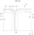
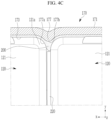
- FIG. 4A to FIG. 4C illustrate processes in which the side plate 170 is fixed to the plurality of unit cells 120 during a manufacturing process of the rechargeable battery module 100.
- the adhesive 200 is provided directly on a side surface having a narrow width of the cases 121 of the plurality of unit cells 120 along the first direction (x).
- the adhesive 200 is also positioned between the unit cells 120 due to its own viscosity, and maintains a state in which it is not completely filled in the space between the unit cells 120.
- An insulating member 220 may be disposed between the plurality of unit cells 120 to prevent an electrical short circuit thereof.
- the side plate 170 is disposed so that the protrusion 177 faces the adhesive 200, and when the side plate 170 is pressed toward the plurality of unit cells 120, as shown in FIG. 4C , the protrusion 177 pushes a corresponding portion of the adhesive 200 positioned between the plurality of unit cells 120, allowing the corresponding portion of the adhesive 200 to be pushed into the space between the plurality of unit cells 120.
- the corresponding portion of the adhesive 200 positioned between the plurality of unit cells 120 may be pushed by the protrusion 177 to a desired position, for example, a position where the adhesive 200 contacts the insulating member 220.
- the first surface 173 of the main body 171 of the side plate 170 may be in close contact with and fixed to the adhesive 200 provided on the side surface having the narrow width of the cases 121 of the plurality of unit cells 120.
- the pressing of the side plate 170 with respect to the plurality of unit cells 120 is preferably performed until a first distance d1 between the side surface having the narrow width of the case 121 of the unit cell 120 and the main body of the side plate and a second distance d2, which is a distance between a curvature portion of the corner portion 121a of the case 121 of the unit cell 120 and the first curvature portion 177a of the protrusion 177, become equal.
- the embossing for forming the protrusion 177 is preferably performed so that the relationship between the distances d1 and d2 may be set.
- the position fixing member 175 provided on the side plate 170 may push the adhesive 120 positioned between the plurality of unit cells 120 to a desired position. Accordingly, the side plate 170 may be firmly fixed to the plurality of unit cells 120 by the adhesive 200 that directly contacts the corner as well as the side surface having the narrow width of the case 121 of the plurality of unit cells 120.
- the fixing structure of the side plate 170 may prevent the plurality of battery cells 120 from moving along the arrangement direction thereof, that is, the first direction (x) in the rechargeable battery module 100.
- the side plate 170 may be designed and prepared in advance so that the position fixing member 175 of the side plate 170 may be inserted into the space between the unit cells 120.
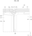
- FIG. 5 schematically illustrates a perspective view of a rechargeable battery module 300 according to another embodiment of the present disclosure.
- the rechargeable battery module 300 according to another embodiment is substantially the same as the rechargeable battery module 100 according to the above-described embodiment. Therefore, for convenience, identical constituent elements are denoted by the same reference numerals.
- the insulating member 220 disposed between a plurality of unit cells (not shown for better understanding and ease of description) is installed in the insulating frame 240, and the protrusion 177, which is the position fixing member 175 of the side plate 170, is inserted into the fixing portion 244 integrally configured at both ends of the insulating frame 240 and fixed by the adhesive 200.
- the fixing portion 244 may be disposed in the space between the plurality of unit cells 120, the inner surface (the surface facing the protrusion) thereof may have a curvature corresponding to the curvature of the first curvature portion 177a and the second curvature portions 177a and 177b of the protrusion 177, and the outer surface (the surface facing the unit cell) thereof may have a curvature corresponding to the curvature of the corner portion 121a of the case 121 of the unit cell 120.
- the side plate 170 may be fixed to the plurality of unit cells 120 by closely contacting the first surface 173 and the protrusion 177 of the main body 171 thereof to the adhesive 200 provided on the side surface having the narrow width of the case 121 of the plurality of unit cells 120 and provided on the inner surface of the fixing portion 244 of the insulating frame 240.
- a rechargeable battery module including a prismatic rechargeable battery has been described as an example, but a battery module having a structure in which unit cells of various types and shapes are stacked and pressed and supported by end plates and side plates may be implemented by applying the characteristic structure of the present disclosure.
Landscapes
- Chemical & Material Sciences (AREA)
- Chemical Kinetics & Catalysis (AREA)
- Electrochemistry (AREA)
- General Chemical & Material Sciences (AREA)
- Engineering & Computer Science (AREA)
- Manufacturing & Machinery (AREA)
- Life Sciences & Earth Sciences (AREA)
- Biophysics (AREA)
- Battery Mounting, Suspending (AREA)
Applications Claiming Priority (2)
| Application Number | Priority Date | Filing Date | Title |
|---|---|---|---|
| KR1020210193101A KR20230102737A (ko) | 2021-12-30 | 2021-12-30 | 이차 전지 모듈 |
| PCT/KR2022/021384 WO2023128555A1 (ko) | 2021-12-30 | 2022-12-27 | 이차 전지 모듈 |
Publications (2)
| Publication Number | Publication Date |
|---|---|
| EP4459768A1 true EP4459768A1 (de) | 2024-11-06 |
| EP4459768A4 EP4459768A4 (de) | 2025-10-15 |
Family
ID=86999833
Family Applications (1)
| Application Number | Title | Priority Date | Filing Date |
|---|---|---|---|
| EP22916696.2A Pending EP4459768A4 (de) | 2021-12-30 | 2022-12-27 | Wiederaufladbares batteriemodul |
Country Status (5)
| Country | Link |
|---|---|
| US (1) | US20250070367A1 (de) |
| EP (1) | EP4459768A4 (de) |
| KR (1) | KR20230102737A (de) |
| CN (1) | CN118661325A (de) |
| WO (1) | WO2023128555A1 (de) |
Families Citing this family (1)
| Publication number | Priority date | Publication date | Assignee | Title |
|---|---|---|---|---|
| KR102705199B1 (ko) * | 2023-11-15 | 2024-09-11 | 주식회사 입실론엑스 | 에너지 저장 장치 |
Family Cites Families (8)
| Publication number | Priority date | Publication date | Assignee | Title |
|---|---|---|---|---|
| JP5542549B2 (ja) * | 2009-08-31 | 2014-07-09 | 株式会社東芝 | 二次電池装置 |
| KR101966352B1 (ko) * | 2011-03-10 | 2019-04-09 | 에스케이이노베이션 주식회사 | 셀 고정 부재가 구비되는 배터리 |
| JP6010326B2 (ja) * | 2011-06-02 | 2016-10-19 | 株式会社東芝 | 二次電池装置、二次電池装置の製造方法 |
| KR102058689B1 (ko) * | 2015-09-22 | 2019-12-23 | 주식회사 엘지화학 | 배터리 모듈, 이러한 배터리 모듈을 포함하는 배터리 팩 및 이러한 배터리 팩을 포함하는 자동차 |
| US10770765B2 (en) * | 2016-09-28 | 2020-09-08 | Lg Chem, Ltd. | Battery module with improved frame structure and frame assembly for the battery module |
| PL3723156T3 (pl) * | 2019-04-12 | 2025-10-06 | Samsung Sdi Co., Ltd. | Element dystansowy dla stosu baterii |
| EP3799148B1 (de) * | 2019-09-30 | 2023-11-15 | Samsung SDI Co., Ltd. | Batteriemodul mit flexibler verbindungsleitung |
| WO2021253353A1 (zh) * | 2020-06-18 | 2021-12-23 | 东莞新能安科技有限公司 | 电池外壳及带有该电池外壳的电池包 |
-
2021
- 2021-12-30 KR KR1020210193101A patent/KR20230102737A/ko active Pending
-
2022
- 2022-12-27 WO PCT/KR2022/021384 patent/WO2023128555A1/ko not_active Ceased
- 2022-12-27 US US18/724,110 patent/US20250070367A1/en active Pending
- 2022-12-27 CN CN202280086814.4A patent/CN118661325A/zh active Pending
- 2022-12-27 EP EP22916696.2A patent/EP4459768A4/de active Pending
Also Published As
| Publication number | Publication date |
|---|---|
| KR20230102737A (ko) | 2023-07-07 |
| CN118661325A (zh) | 2024-09-17 |
| US20250070367A1 (en) | 2025-02-27 |
| EP4459768A4 (de) | 2025-10-15 |
| WO2023128555A1 (ko) | 2023-07-06 |
Similar Documents
| Publication | Publication Date | Title |
|---|---|---|
| US8852789B2 (en) | Battery module having battery cell holder | |
| US9203065B2 (en) | Battery module | |
| CN107591500B (zh) | 电池子模块载体、电池子模块、电池系统和车辆 | |
| US11431063B2 (en) | Battery module having structure facilitating series-parallel connections and battery pack comprising same | |
| US9455425B2 (en) | Battery module | |
| US9450219B2 (en) | Battery module | |
| EP2562842B1 (de) | Batteriemodul | |
| EP2590242B1 (de) | Verfahren und Vorrichtung zur Verbesserung der Leistung eines Batteriemoduls durch Angleichen der Spannung | |
| US20150086834A1 (en) | Battery module having holder | |
| KR101526457B1 (ko) | 라운드 코너를 포함하는 전극조립체 | |
| EP2450990A2 (de) | Batteriemodul mit Batteriezellenhalter | |
| CN113748563A (zh) | 电池模块及其制造方法 | |
| CN109075304B (zh) | 具有隔膜的可再充电电池 | |
| EP4207448A2 (de) | Sammelschienenhalter, sammelschienenanordnung und batteriemodul | |
| EP4053988B1 (de) | Batteriemodul mit schienenartiger halterung und batteriepack damit | |
| EP4459768A1 (de) | Wiederaufladbares batteriemodul | |
| EP4145605A1 (de) | Wiederaufladbares batteriemodul | |
| CN113508492A (zh) | 电化学电池模块 | |
| CN109923730B (zh) | 电池模块和包括该电池模块的电池组 | |
| EP4266465A1 (de) | Batteriemodul | |
| EP4376185A1 (de) | Batteriepack und verfahren zur montage davon | |
| US20250132439A1 (en) | Rechargeable battery module | |
| CN118801032A (zh) | 可再充电电池模组 | |
| KR20230061982A (ko) | 이차 전지 |
Legal Events
| Date | Code | Title | Description |
|---|---|---|---|
| STAA | Information on the status of an ep patent application or granted ep patent |
Free format text: STATUS: THE INTERNATIONAL PUBLICATION HAS BEEN MADE |
|
| PUAI | Public reference made under article 153(3) epc to a published international application that has entered the european phase |
Free format text: ORIGINAL CODE: 0009012 |
|
| STAA | Information on the status of an ep patent application or granted ep patent |
Free format text: STATUS: REQUEST FOR EXAMINATION WAS MADE |
|
| 17P | Request for examination filed |
Effective date: 20240620 |
|
| AK | Designated contracting states |
Kind code of ref document: A1 Designated state(s): AL AT BE BG CH CY CZ DE DK EE ES FI FR GB GR HR HU IE IS IT LI LT LU LV MC ME MK MT NL NO PL PT RO RS SE SI SK SM TR |
|
| DAV | Request for validation of the european patent (deleted) | ||
| DAX | Request for extension of the european patent (deleted) | ||
| REG | Reference to a national code |
Ref country code: DE Ref legal event code: R079 Free format text: PREVIOUS MAIN CLASS: H01M0050289000 Ipc: H01M0050209000 |
|
| A4 | Supplementary search report drawn up and despatched |
Effective date: 20250915 |
|
| RIC1 | Information provided on ipc code assigned before grant |
Ipc: H01M 50/209 20210101AFI20250909BHEP Ipc: H01M 50/264 20210101ALI20250909BHEP Ipc: H01M 50/289 20210101ALI20250909BHEP Ipc: H01M 50/291 20210101ALI20250909BHEP Ipc: H01M 10/04 20060101ALI20250909BHEP Ipc: H01M 50/204 20210101ALI20250909BHEP Ipc: H01M 10/623 20140101ALI20250909BHEP Ipc: H01M 10/625 20140101ALI20250909BHEP |