EP4459727A1 - Procédé de fabrication d'un accumulateur et accumulateur - Google Patents
Procédé de fabrication d'un accumulateur et accumulateur Download PDFInfo
- Publication number
- EP4459727A1 EP4459727A1 EP24173484.7A EP24173484A EP4459727A1 EP 4459727 A1 EP4459727 A1 EP 4459727A1 EP 24173484 A EP24173484 A EP 24173484A EP 4459727 A1 EP4459727 A1 EP 4459727A1
- Authority
- EP
- European Patent Office
- Prior art keywords
- contact element
- edge region
- metal foil
- electrode
- housing part
- Prior art date
- Legal status (The legal status is an assumption and is not a legal conclusion. Google has not performed a legal analysis and makes no representation as to the accuracy of the status listed.)
- Pending
Links
Images


Classifications
-
- H—ELECTRICITY
- H01—ELECTRIC ELEMENTS
- H01M—PROCESSES OR MEANS, e.g. BATTERIES, FOR THE DIRECT CONVERSION OF CHEMICAL ENERGY INTO ELECTRICAL ENERGY
- H01M10/00—Secondary cells; Manufacture thereof
- H01M10/04—Construction or manufacture in general
- H01M10/0431—Cells with wound or folded electrodes
-
- H—ELECTRICITY
- H01—ELECTRIC ELEMENTS
- H01M—PROCESSES OR MEANS, e.g. BATTERIES, FOR THE DIRECT CONVERSION OF CHEMICAL ENERGY INTO ELECTRICAL ENERGY
- H01M10/00—Secondary cells; Manufacture thereof
- H01M10/05—Accumulators with non-aqueous electrolyte
- H01M10/058—Construction or manufacture
- H01M10/0587—Construction or manufacture of accumulators having only wound construction elements, i.e. wound positive electrodes, wound negative electrodes and wound separators
-
- H—ELECTRICITY
- H01—ELECTRIC ELEMENTS
- H01M—PROCESSES OR MEANS, e.g. BATTERIES, FOR THE DIRECT CONVERSION OF CHEMICAL ENERGY INTO ELECTRICAL ENERGY
- H01M50/00—Constructional details or processes of manufacture of the non-active parts of electrochemical cells other than fuel cells, e.g. hybrid cells
- H01M50/10—Primary casings; Jackets or wrappings
- H01M50/102—Primary casings; Jackets or wrappings characterised by their shape or physical structure
- H01M50/107—Primary casings; Jackets or wrappings characterised by their shape or physical structure having curved cross-section, e.g. round or elliptic
-
- H—ELECTRICITY
- H01—ELECTRIC ELEMENTS
- H01M—PROCESSES OR MEANS, e.g. BATTERIES, FOR THE DIRECT CONVERSION OF CHEMICAL ENERGY INTO ELECTRICAL ENERGY
- H01M50/00—Constructional details or processes of manufacture of the non-active parts of electrochemical cells other than fuel cells, e.g. hybrid cells
- H01M50/50—Current conducting connections for cells or batteries
- H01M50/543—Terminals
- H01M50/547—Terminals characterised by the disposition of the terminals on the cells
- H01M50/548—Terminals characterised by the disposition of the terminals on the cells on opposite sides of the cell
-
- H—ELECTRICITY
- H01—ELECTRIC ELEMENTS
- H01M—PROCESSES OR MEANS, e.g. BATTERIES, FOR THE DIRECT CONVERSION OF CHEMICAL ENERGY INTO ELECTRICAL ENERGY
- H01M50/00—Constructional details or processes of manufacture of the non-active parts of electrochemical cells other than fuel cells, e.g. hybrid cells
- H01M50/50—Current conducting connections for cells or batteries
- H01M50/543—Terminals
- H01M50/552—Terminals characterised by their shape
-
- H—ELECTRICITY
- H01—ELECTRIC ELEMENTS
- H01M—PROCESSES OR MEANS, e.g. BATTERIES, FOR THE DIRECT CONVERSION OF CHEMICAL ENERGY INTO ELECTRICAL ENERGY
- H01M50/00—Constructional details or processes of manufacture of the non-active parts of electrochemical cells other than fuel cells, e.g. hybrid cells
- H01M50/50—Current conducting connections for cells or batteries
- H01M50/543—Terminals
- H01M50/564—Terminals characterised by their manufacturing process
- H01M50/566—Terminals characterised by their manufacturing process by welding, soldering or brazing
Definitions
- the invention relates to a method for producing a rechargeable battery, in particular a method for producing an electrode lead of a rechargeable battery, and a rechargeable battery that can be produced by the method according to the invention.
- the metal foils which in particular contact the anode and/or the cathode of the accumulator, are wound together with other flat components of the accumulator, such as in particular the electrodes of the accumulator, preferably in a spiral shape, to form an electrode coil.
- Such accumulators can be manufactured by placing the electrode windings in cup-shaped housing parts.
- the cup-shaped housing part can be closed with a lid, which can be electrically insulated from the housing part.
- a pole can be led through the lid, which is electrically contacted with one of the metal foils of the electrode winding.
- the other metal foil of the electrode winding is electrically contacted with the cup, which thus forms the second pole of the resulting accumulator.
- a method for producing an accumulator and an accumulator are known in which edge areas of the metal foils for contacting the electrodes on the two opposite end faces of the electrode winding protrude from the other layered components of the electrode winding.
- the edge areas are welded to contact elements, which in turn are welded to poles that are passed through corresponding insulating covers on both end faces of the circular cylindrical accumulator.
- the contact enables short current paths and such accumulators are well suited for applications in which the accumulators must deliver high electrical power.
- the disadvantage is that such accumulators require more installation space and are more expensive to manufacture, since corresponding contact elements with attached poles have to be installed on both end faces of the circular cylindrical housing.
- An accumulator with a more economical installation space requirement can be manufactured by, for example, DE 10 2022 111 706.5 , the electrode coil is welded to the bottom of a cup-shaped housing part.
- the welding process is difficult to master in practice and there is always a risk of leaks in the housing if holes are accidentally created in the bottom during welding.
- the object of the invention is therefore to provide a method for producing an accumulator and an accumulator in which the aforementioned disadvantages do not occur or at least occur to a reduced extent.
- the method for producing the accumulator provides that metal foils which contact the electrodes of the accumulator are wound together with the electrodes of the accumulator to form an at least substantially cylindrical, in particular circular cylindrical, electrode coil in such a way that on one of the two opposite end faces of the electrode coil a first edge region of a first metal foil for contacting a first electrode protrudes from the other layered components of the electrode coil.
- the end faces are understood to mean the sides of the electrode coil that correspond to the base areas of the circular cylinder describing the geometric shape of the electrode coil.
- the electrode coil is introduced into a cup-shaped housing part and, in order to contact the first electrode of the accumulator, the first edge region of the first metal foil of the first electrode and/or a first contact element that is electrically conductively connected to the first edge region is glued to the bottom of the housing part.
- the electrode coil with the protruding first edge region of the first metal foil and/or the first contact element that is electrically conductively connected to the first edge region is pressed in particular onto the bottom of the housing part.
- an electrically conductive adhesive is used in the process for producing the bond.
- Such an electrically conductive adhesive has the advantage that an electrical connection between the first metal foil or the first contact element and the floor is established via the adhesive.
- An electrically conductive adhesive is to be understood here in particular as a permanently electrically conductive adhesive, i.e. in particular an adhesive that has a corresponding electrical conductivity after it has completely hardened.
- the first electrode can in particular be the cathode.
- the metal foil used to contact the first electrode, and in particular the first contact element in this case preferably consists of aluminum or an aluminum alloy.
- the housing part and in particular the base of the housing part in this case also consists in particular of aluminum or an aluminum alloy.
- the first electrode can alternatively be the anode.
- the metal foil used to contact the first electrode, and in particular the first contact element in this case preferably consists of copper or a copper alloy.
- the housing part and in particular the base of the housing part in this case consists in particular of a steel.
- the housing part can in particular be deep-drawn. It has been shown that by means of deep-drawing, which preferably takes place in several stages, sufficient dimensional accuracy of the housing part and in particular of the base can be achieved in order to carry out the bonding in a reproducible manner.
- the method provides in particular that the edge region of the first metal foil is bent over, at least in partial sections, before the edge region is bonded to the floor, in such a way that a surface bonding of at least partial sections of the edge region to the floor is achieved. It has been shown that the bonding of the floor to the metal foil can be improved if the metal foil and the floor lie flat against each other. For this purpose, it can be useful if the edge area or at least sections of the edge area are bent over. In this context, the edge area or sections of the edge area are bent over, at least essentially, by 90°.
- the edge region can be cut, particularly before the sections are bent, so that sections of the edge region are created that can be bent independently of one another. This can significantly facilitate the bending of the edge region by approximately 90°, particularly in the case of a circular cylindrical electrode coil and a corresponding spiral course of the edge region protruding from the electrode coil. It can happen that sections, particularly adjacent sections, of the edge region overlap after bending.
- the edge region is welded to the first contact element before the first contact element connected to the edge region is glued to the base.
- the method then provides in particular for the electrode coil with the welded contact element to be introduced into the housing part for the purpose of gluing.
- the first contact element can be welded to the edge region significantly more easily if the welding takes place before the electrode coil is introduced into the housing part.
- the bonding between the first contact element and the base can take place largely independently of whether the first contact element is already welded to the electrode coil.
- the production sequence of first welding the first contact element to the electrode coil and only then introducing this into the housing part in order to glue the first contact element to the base is therefore advantageous.
- the battery is preferably a lithium-ion battery.
- Lithium-ion batteries enable the storage of comparatively large amounts of energy with low weight and space requirements.
- the method according to the invention therefore offers high added value, particularly in the production of these accumulators.
- the accumulator preferably has an at least substantially cylindrical geometry.
- An at least substantially cylindrical geometry is to be understood in particular as a geometry in which the main dimensions of the accumulator form a cylindrical geometry.
- Individual elements of the accumulator, for example the poles, can have a design that deviates from a strict cylindrical shape. Accumulators with a cylindrical geometry are already standardized as a design, which is why the accumulators can usually be easily replaced.
- the accumulator takes on a circular-cylindrical shape, at least essentially.
- the axis of the spiral winding preferably corresponds to the central axis of the cylinder.
- the axis here is understood to mean in particular the linear center of the spiral winding.
- a physical axis in the sense of a corresponding component can be present, but is not absolutely necessary.
- the method can provide that a second metal foil is welded to a second contact element to contact a second electrode of the accumulator.
- the contact element is particularly flat and oriented at right angles to the axis of the electrode coil.
- the ordinal number "second" is used only to linguistically distinguish this contact element from the first contact element. Under no circumstances does the second contact element necessarily require the presence of the optional first contact element.
- the second metal foil in particular the area of the second metal foil to be connected to the bottom of the second contact element, protrudes in the direction of the second contact element, preferably in the direction of the axis of the electrode winding, relative to the other flat or layered components of the accumulator, such as the cathode, the anode or another metal foil.
- the method can provide that, in order to weld the first edge region to the first contact element and/or to weld the second edge region to the second contact element, the first and/or the second edge region is brought into contact with a first surface of the respective contact element oriented at right angles to the respective metal foil and is welded to the respective contact element by applying a laser beam to a second surface of the respective contact element facing away from the first surface of the respective contact element.
- a region of the first metal foil and/or a region of the second metal foil is bent over in order to weld the first edge region to the first contact element and/or to weld the second edge region to the second contact element.
- the bending of the region of the respective metal foil can expediently take place before and/or during the winding of the metal foil.
- a variety of bending methods can be used, preferably a flanging method.
- the welding of the metal foil to the first contact element and/or the second contact element then preferably takes place in the region of the bend created. This increases the contact surface of the metal foil on the first contact element and/or the second contact element, which has a positive effect on the welding.
- the bend can be a bend of 180°, for example.
- edge region which is connected to the contact element does not, in case of doubt, mean the edge region of the original metal foil before bending, but rather the part of the metal foil which, after the metal foil has been bent, forms the new edge of the metal foil created by the bending.
- the first metal foil and/or the second metal foil protrudes from the other layered components of the accumulator by at least 1 mm, preferably at least 2 mm, and/or at most 8 mm, preferably at most 6 mm.
- This protruding area of the metal foil enables It is possible to contact the metal foil using the method according to the invention, whereby the risk of impairing and/or damaging other layered components of the accumulator by the welding is excluded or at least reduced.
- the thickness of the first and/or second contact element is preferably at least 0.05 mm, particularly preferably at least 0.15 mm, and/or preferably at most 1.5 mm, particularly preferably at most 0.6 mm.
- first and/or second metal foil is welded to a projecting region of the first surface of the first contact element and/or the first surface of the second.
- a projecting region on the first contact element and/or the second contact element makes it possible to establish a defined local contact between the metal foil and the first contact element and/or the second contact element at which the welding takes place.
- the respective contact element preferably has a recessed region on its surface opposite the projecting region. This recessed region is preferably designed to be complementary to the projecting region in terms of its shape.
- the projecting region and the recessed region can be designed together as a bead in the respective contact element. This design has the advantage that it is easy to produce and means that the thickness of the respective contact element in the affected region remains at least approximately constant.
- the projecting region preferably projects by at least 0.3 mm, particularly preferably by at least 0.5 mm, and/or preferably by at most 2 mm, particularly preferably by at most 1.5 mm, relative to the surrounding first surface of the respective contact element.
- the respective projecting area or the respective bead is preferably linear and has a width of preferably at least 0.5 mm, particularly preferably at least 1 mm, and/or preferably at most 5 mm, particularly preferably at most 3 mm.
- the protruding area in the plane in which the respective metal foil comes into contact with a protruding area, the protruding area preferably with the metal foil. If the accumulator is folded and/or wound up, this results in a plurality of individual contact points between the edge area of the respective metal foil and the respective contact element, which leads to reliable welding at these points.
- the first metal foil and/or the second metal foil preferably has a thickness of at least 0.001 mm, particularly preferably of at least 0.005 mm, and/or preferably of at most 0.02 mm, particularly preferably of at most 0.012 mm.
- a pole element is connected, in particular welded, to the second contact element to form the pole of the accumulator.
- the geometry of the second contact element which is preferably flat or plate-shaped, can be designed independently of the shape of the pole. This is particularly advantageous because the shape of the pole is subject to restrictions that regularly depend on the intended use of the accumulator produced and/or technical standards.
- the pole element can be connected to the second contact element, for example, by means of an overlap weld or a fillet weld.
- connection of the pole element to the second contact element can be carried out with the same laser as the welding of the metal foil to the second contact element. This makes it possible, for example, to weld the metal foil to the second contact element and to weld the pole element to the contact element in the same device, which simplifies the manufacture of the accumulator.
- the pole element can, for example, have a thread to form the pole of the accumulator. With such a thread, the accumulator can be reliably electrically connected to the device supplied by the accumulator. become.
- the pole element has a sealing surface.
- the sealing surface serves in particular to connect the pole element to the housing of the accumulator.
- a sealed and preferably electrically insulated accumulator can be created, with the pole element remaining accessible for the purpose of electrically contacting the accumulator.
- the electrical insulation of the accumulator can be arranged between the housing part and a cover of the housing and/or the pole element and a cover of the housing.
- the pole element preferably covers - at least partially - weld seams for connecting the second metal foil to the second contact element.
- Such a design of the accumulator can be produced in particular by first welding the second metal foil to the second contact element and then the second contact element to the pole element.
- the pole element and in particular the sealing surface of the pole element can be arranged in an area on the second surface of the second contact element, which is also used for welding the second contact element to the metal foil.
- pole element is pressed against the second contact element when it is welded to the second contact element. It has been shown that in this way the formation of gaps that can occur between the pole element and the second contact element can be effectively prevented.
- the laser used to weld the first metal foil to the first contact element, the second metal foil to the second contact element and/or the second contact element to the pole element is preferably a fiber laser.
- Fiber lasers also referred to as fibers, use the doped core of a glass fiber as an active medium.
- the advantage of fiber lasers is that the possible great length of the laser-active fiber enables high amplification.
- the average power, in particular the constant power of the laser in continuous operation of the laser when welding the first metal foil to the first contact element and/or the second metal foil to the second contact element is at least 100 W, particularly preferably at least 200 W and/or at most 700 W, particularly preferably at most 500 W. At these powers, particularly good results with regard to welding could be achieved.
- the average power, in particular the constant power of the laser in continuous operation is preferably at least 500 W, particularly preferably at least 700 W, and/or preferably at most 1500 W, particularly preferably at most 1000 W.
- the wavelength of the laser used to weld the first metal foil to the first contact element, the second metal foil to the second contact element and/or the second contact element to the pole element is preferably 1070 nm. Good results can be achieved with a laser of this wavelength, and lasers of this wavelength are also commercially available.
- a single-mode laser is used to weld the first metal foil to the first contact element, the second metal foil to the second contact element and/or the second contact element to the pole element.
- these lasers only waves of a single desired mode are amplified, while other modes are suppressed.
- Such lasers ideally have only a single, narrow spectral line. This means that the laser beam reaches a high optical quality, which particularly affects its good focusability.
- the laser used to weld the first metal foil to the first contact element, the second metal foil to the second contact element and/or the second contact element to the pole element is focused using a focusing optic.
- a focusing optic enables the laser beam to be bundled. It has been shown that for the method according to the invention, focusing optics with a focal length of at least 10 mm, preferably at least 100 mm and/or at most 5000 mm, preferably at most 500 mm, lead to particularly good results. This applies both to the welding of the respective metal foil to the corresponding contact element and to the welding of the second contact element to the pole element.
- the laser beam used to weld the first metal foil to the first contact element, the second metal foil to the second contact element and/or the second contact element to the pole element has a focus diameter of at least 1 ⁇ m, preferably at least 10 ⁇ m and/or at most 500 ⁇ m, preferably at most 50 ⁇ m. It has been shown that with these focus diameters, a particularly good welding of the respective metal foil and/or the pole element to the corresponding contact element can be achieved. This applies both to the welding of the respective metal foil to the corresponding contact element and to the welding of the second contact element to the pole element.
- the point of impact of the laser on the respective contact element which is preferably the focus of the laser beam, is moved along a movement path that results from the superposition of a feed movement and an oscillating movement.
- this may apply to the point of impact of the laser beam on the pole element.
- the feed movement is the movement with which the point of impact of the laser follows the course of the weld seam to be produced.
- the speed The speed at which the point of impact moves on the surface of the respective contact element or, if applicable, the pole element along the weld seam is referred to in this context as the feed rate.
- the feed rate is preferably at least 10 mm/s, preferably at least 70 mm/s, and/or at most 200 mm/s, preferably at most 150 mm/s. It has been shown that these feed rates enable the weld seams to be produced comparatively quickly while at the same time maintaining high quality. It is understood that - in the case of superimposing the feed movement with an oscillating movement - the feed rate is not the absolute speed of the resulting movement in the feed direction, but an average movement speed in the feed direction.
- the oscillating movement which is preferably superimposed on the feed movement, preferably has a frequency of at least 100 Hz, preferably at least 500 Hz and/or at most 5000 Hz, preferably at most 1500 Hz.
- the amplitude of the oscillating movement is preferably at least 0.02 mm, preferably at least 0.1 mm, and/or at most 0.5 mm, preferably at most 1 mm. It has been shown that a local power modulation can be realized, which enables particularly good melt pool control.
- the radius of the circle described by the oscillating movement corresponds to the amplitude with respect to the values given above.
- an average amplitude is to be regarded as the amplitude.
- the method can in particular provide that the power of the laser beam is varied during the welding of the metal foil to the first contact element and/or the second contact element.
- the power of the laser beam can be increased at the beginning of the production of a weld seam and/or reduced at the end of the production of a weld seam.
- the increase and/or lowering the power can be done continuously, for example in the form of a ramp. It has been shown that this can prevent the formation of holes in the contact element during welding.
- the welding of the metal foils to the respective contact element and/or the bending of the metal foils takes place before the electrode coil is introduced into the housing part and/or before the first edge region and/or the first contact element is provided with adhesive, in particular conductive adhesive, before being introduced into the housing part.
- the adhesive can also be introduced into the housing part before the electrode coil is introduced into the housing part.
- the base of the housing part in particular is provided with the adhesive before the electrode coil is introduced into the housing part.
- the accumulator can be provided with a cover.
- the method can provide for a cover to be attached to the housing part. This can be done, for example, by welding, or alternatively and/or additionally, for example, by flanging, edge regions of the cover and the housing part.
- the accumulator can be filled with an electrolyte.
- the electrolyte is filled in particular through a filling opening provided for this purpose in the accumulator, which is closed after the accumulator has been filled with the electrolyte.
- the method can provide that a defined time interval between the introduction of the adhesive and the filling of the battery with the electrolyte is maintained or at least not undercut. adhesive time to cure before the adhesive is exposed to the electrolyte.
- the invention further relates to an accumulator which can be produced using the method described above.
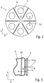
- the exemplary accumulator advantageously has a second contact element 2, which is welded to a second metal foil 3 of an electrode coil 1.
- a second contact element 2 which is welded to a second metal foil 3 of an electrode coil 1.
- An edge region of the second metal foil 3 is brought into contact with a first surface 4 of the contact element 2 during the electrode winding 1 shown.
- the second contact element 2 is welded to the second metal foil 3.
- the second metal foil 3 is wound with other flat components of the accumulator, in particular the electrodes, to form a spiral winding. This results in a circular cylindrical structure of the electrode winding 1.
- the second metal foil 3 is arranged at right angles to the first surface 4 of the second contact element 2.
- the second contact element 2 in the example shown has an opening 7, preferably a plurality of openings 7.
- the first surface 4 of the second contact element 2 in the example shown has a plurality of projecting regions 8.
- the projecting regions 8 are advantageously designed as beads 9.
- the second metal foil 3 and the projecting regions 8 are advantageously oriented to one another in such a way that they cross one another.
- the second contact element 2 has a thickness of 0.3 mm.
- the projecting areas 8 protrude by 0.4 mm compared to the first surface.
- the second metal foil 3 has a bent region 10.
- the second metal foil 3 rests in the region of the bend 11 on the projecting region 9 of the first surface 4 of the second contact element 2.
- the thickness of the second metal foil 3 is preferably 0.01 mm.
- FIG. 3 corresponding section line 12 in Fig. 2 shown schematically.
- the second metal foil 3 and the second contact element 2 are each welded with a single-mode fiber laser with a wavelength of 1070 nm.
- a single-mode fiber laser with a wavelength of 1070 nm.
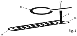
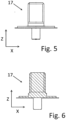
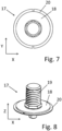
- the laser can also be used in the context of the method according to the invention to weld a pole element 17 to the second contact element 2.
- the pole element 17 has a sealing surface 18. It serves to provide a pole of the accumulator, which in the example shown expediently has a thread 19.
- the pole element 17 with its sealing surface 18 partially covers the beads 9 along which the weld seams between the second contact element 2 and the second metal foil 3 are made.
- connection area 20 surrounds the sealing surface 18.
- the laser power is expediently increased to 800 W, for example.
- the focal length of the focusing optics used in the exemplary embodiment is 330 mm.
- the feed movement 14 of the laser beam is also superimposed by an oscillating movement 15 during the exemplary welding of the pole element.
- the frequency of the circular oscillating movement is 800 Hz, for example, and the amplitude is 0.2 mm.
- the feed speed can be 100 mm/s, for example.
- the pole element 17 is advantageously made of the same material as the second contact element 2, preferably copper.
- the unit thus produced from the electrode coil 1 and the second contact element 2 with the welded pole element 17 can now be introduced into a cup-shaped housing part 21.
- a first edge region of a first metal foil 23 of a first electrode of the electrode coil 1 can be glued to the base 22 of the housing part 21.
- sections of the first edge region of the first metal foil 23 can be bent, in particular by 90° as shown, in order to enable a surface bond between the metal foil 23 and the base 22 of the housing part 21.
- Fig. 10 an alternative embodiment is shown in which, during the manufacture of the battery shown, the first edge region of the first metal foil 23 is not glued directly to the base 22 of the housing part 21, but is first welded to a first contact element 25.
- the first contact element 25 is in turn glued to the base 22 of the housing part 21.
- the welding of the first contact element 25 to the first edge region of the first metal foil 23 can be carried out analogously to the welding of the second contact element 2 to the second metal foil 3 described above.
- the first contact element 25 can have corresponding projecting regions 8 designed as beads 9, analogously to the second contact element 2 described above, as is shown by way of example in Figure 10 is shown.
Landscapes
- Chemical & Material Sciences (AREA)
- Chemical Kinetics & Catalysis (AREA)
- Electrochemistry (AREA)
- General Chemical & Material Sciences (AREA)
- Engineering & Computer Science (AREA)
- Manufacturing & Machinery (AREA)
- Connection Of Batteries Or Terminals (AREA)
Applications Claiming Priority (1)
| Application Number | Priority Date | Filing Date | Title |
|---|---|---|---|
| DE102023111321.6A DE102023111321A1 (de) | 2023-05-02 | 2023-05-02 | Verfahren zur Herstellung eines Akkumulators und Akkumulator |
Publications (1)
| Publication Number | Publication Date |
|---|---|
| EP4459727A1 true EP4459727A1 (fr) | 2024-11-06 |
Family
ID=90925149
Family Applications (1)
| Application Number | Title | Priority Date | Filing Date |
|---|---|---|---|
| EP24173484.7A Pending EP4459727A1 (fr) | 2023-05-02 | 2024-04-30 | Procédé de fabrication d'un accumulateur et accumulateur |
Country Status (2)
| Country | Link |
|---|---|
| EP (1) | EP4459727A1 (fr) |
| DE (1) | DE102023111321A1 (fr) |
Citations (4)
| Publication number | Priority date | Publication date | Assignee | Title |
|---|---|---|---|---|
| CN203617380U (zh) * | 2013-12-18 | 2014-05-28 | 山东精工电子科技有限公司 | 圆柱形抗震锂离子电池 |
| DE102017006229A1 (de) | 2017-07-03 | 2019-01-03 | Monbat New Power GmbH | Verfahren und Vorrichtung zur Herstellung eines Akkumulators und Akkumulator |
| CN113555602A (zh) * | 2021-08-19 | 2021-10-26 | 多氟多新能源科技有限公司 | 一种新型圆柱锂离子电池及其制作方法 |
| DE102022111706A1 (de) | 2022-05-10 | 2023-11-16 | Monbat New Power GmbH | Verfahren zur Herstellung eines Akkumulators und Akkumulator |
Family Cites Families (2)
| Publication number | Priority date | Publication date | Assignee | Title |
|---|---|---|---|---|
| CN102197530B (zh) * | 2008-09-09 | 2015-10-21 | 江森自控帅福得先进能源动力系统有限责任公司 | 具有折叠电极的电化学电池单元 |
| KR102616467B1 (ko) * | 2018-09-27 | 2023-12-21 | 삼성에스디아이 주식회사 | 이차 전지 |
-
2023
- 2023-05-02 DE DE102023111321.6A patent/DE102023111321A1/de active Pending
-
2024
- 2024-04-30 EP EP24173484.7A patent/EP4459727A1/fr active Pending
Patent Citations (5)
| Publication number | Priority date | Publication date | Assignee | Title |
|---|---|---|---|---|
| CN203617380U (zh) * | 2013-12-18 | 2014-05-28 | 山东精工电子科技有限公司 | 圆柱形抗震锂离子电池 |
| DE102017006229A1 (de) | 2017-07-03 | 2019-01-03 | Monbat New Power GmbH | Verfahren und Vorrichtung zur Herstellung eines Akkumulators und Akkumulator |
| EP3649683B1 (fr) * | 2017-07-03 | 2021-10-27 | Monbat New Power GmbH | Procédé et dispositif pour la fabrication d'un accumulateur et accumulateur |
| CN113555602A (zh) * | 2021-08-19 | 2021-10-26 | 多氟多新能源科技有限公司 | 一种新型圆柱锂离子电池及其制作方法 |
| DE102022111706A1 (de) | 2022-05-10 | 2023-11-16 | Monbat New Power GmbH | Verfahren zur Herstellung eines Akkumulators und Akkumulator |
Also Published As
| Publication number | Publication date |
|---|---|
| DE102023111321A1 (de) | 2024-11-07 |
Similar Documents
| Publication | Publication Date | Title |
|---|---|---|
| EP3649683B1 (fr) | Procédé et dispositif pour la fabrication d'un accumulateur et accumulateur | |
| DE202022003221U1 (de) | Batterie mit Stromabnehmer, Batteriepack und Fahrzeug mit einer solchen Batterie | |
| EP3017509B1 (fr) | Procédé de raccordement d'un conducteur électrique à un élément de contact électrique | |
| DE60003862T2 (de) | Dichte Batterie, geeignet für die Herstellung in einer schlanken rechteckigen Form | |
| DE112012006588T5 (de) | Verfahren zur Herstellung einer Batterie und Batterie | |
| EP2381234B1 (fr) | Composant fonctionnel comme moyen de mesure de pression doté d'un film métallique en matériau spécial, procédé de soudage d'un film métallique en matériau spécial et dispositif de soudage au rayon laser associé | |
| EP3642898A2 (fr) | Bloc-batterie | |
| EP3555964B1 (fr) | Raccordement d'un connecteur électrique et d'un conducteur multibrin | |
| DE102010013351A1 (de) | Kontaktelement für Ableiter galvanischer Zellen | |
| EP2978085A2 (fr) | Méthode et assemblage pour connexion electrique de fils métalliques | |
| EP4117066B1 (fr) | Procédé et dispositif de fabrication d'un composant pour un élément de batterie, ainsi que composant | |
| DE102011085467A1 (de) | Elektrochemische Vorrichtung | |
| EP3878248B1 (fr) | Système de carte de circuits imprimés, accumulateur d'énergie électrique et procédé de fabrication d'un système de carte de circuits imprimés | |
| DE102022111706A1 (de) | Verfahren zur Herstellung eines Akkumulators und Akkumulator | |
| DE202023003047U1 (de) | Zylindrische Batteriezelle, Batteriepack und Fahrzeug | |
| WO2019040956A1 (fr) | Composant de stator pour machine électrique | |
| DE102012216475A1 (de) | Überlappschweißung von Zellverbindern an Batteriezellen | |
| WO2011012201A1 (fr) | Batterie et procédé de production d'une batterie | |
| EP0133883B1 (fr) | Connecteur pour soudage par ultrasons | |
| DE102016206334A1 (de) | Energiespeicherzellengehäuse, Engergiespeicherzele und Verfahren zu deren Herstellung | |
| EP4459727A1 (fr) | Procédé de fabrication d'un accumulateur et accumulateur | |
| DE102016225252A1 (de) | Elektrischer Energiespeicher, insbesondere Batteriezelle, mit Bauraum-optimierter Elektrodenverschaltung | |
| DE102022111707A1 (de) | Verfahren zur Herstellung eines Akkumulators und Akkumulator | |
| DE102012204377B4 (de) | Verfahren zum Strahlschweißen eines Mehrblech-Arbeitsstapels oder eines Batteriemoduls | |
| DE102012025004A1 (de) | Fügeverbindung zwischen einem Polterminal, einer elektrischen Speicherzelle und einem Polverbinder, Speicherzellen-Pack mit einer Mehrzahl derartiger Speicherzellen sowie Verfahren zur Herstellung besagter Fügeverbindung |
Legal Events
| Date | Code | Title | Description |
|---|---|---|---|
| PUAI | Public reference made under article 153(3) epc to a published international application that has entered the european phase |
Free format text: ORIGINAL CODE: 0009012 |
|
| STAA | Information on the status of an ep patent application or granted ep patent |
Free format text: STATUS: THE APPLICATION HAS BEEN PUBLISHED |
|
| AK | Designated contracting states |
Kind code of ref document: A1 Designated state(s): AL AT BE BG CH CY CZ DE DK EE ES FI FR GB GR HR HU IE IS IT LI LT LU LV MC ME MK MT NL NO PL PT RO RS SE SI SK SM TR |
|
| STAA | Information on the status of an ep patent application or granted ep patent |
Free format text: STATUS: REQUEST FOR EXAMINATION WAS MADE |
|
| 17P | Request for examination filed |
Effective date: 20250506 |