EP4459727A1 - Method for producing a rechargeable battery, and rechargeable battery - Google Patents
Method for producing a rechargeable battery, and rechargeable battery Download PDFInfo
- Publication number
- EP4459727A1 EP4459727A1 EP24173484.7A EP24173484A EP4459727A1 EP 4459727 A1 EP4459727 A1 EP 4459727A1 EP 24173484 A EP24173484 A EP 24173484A EP 4459727 A1 EP4459727 A1 EP 4459727A1
- Authority
- EP
- European Patent Office
- Prior art keywords
- contact element
- edge region
- metal foil
- electrode
- housing part
- Prior art date
- Legal status (The legal status is an assumption and is not a legal conclusion. Google has not performed a legal analysis and makes no representation as to the accuracy of the status listed.)
- Pending
Links
Images


Classifications
-
- H—ELECTRICITY
- H01—ELECTRIC ELEMENTS
- H01M—PROCESSES OR MEANS, e.g. BATTERIES, FOR THE DIRECT CONVERSION OF CHEMICAL ENERGY INTO ELECTRICAL ENERGY
- H01M10/00—Secondary cells; Manufacture thereof
- H01M10/04—Construction or manufacture in general
- H01M10/0431—Cells with wound or folded electrodes
-
- H—ELECTRICITY
- H01—ELECTRIC ELEMENTS
- H01M—PROCESSES OR MEANS, e.g. BATTERIES, FOR THE DIRECT CONVERSION OF CHEMICAL ENERGY INTO ELECTRICAL ENERGY
- H01M10/00—Secondary cells; Manufacture thereof
- H01M10/05—Accumulators with non-aqueous electrolyte
- H01M10/058—Construction or manufacture
- H01M10/0587—Construction or manufacture of accumulators having only wound construction elements, i.e. wound positive electrodes, wound negative electrodes and wound separators
-
- H—ELECTRICITY
- H01—ELECTRIC ELEMENTS
- H01M—PROCESSES OR MEANS, e.g. BATTERIES, FOR THE DIRECT CONVERSION OF CHEMICAL ENERGY INTO ELECTRICAL ENERGY
- H01M50/00—Constructional details or processes of manufacture of the non-active parts of electrochemical cells other than fuel cells, e.g. hybrid cells
- H01M50/10—Primary casings; Jackets or wrappings
- H01M50/102—Primary casings; Jackets or wrappings characterised by their shape or physical structure
- H01M50/107—Primary casings; Jackets or wrappings characterised by their shape or physical structure having curved cross-section, e.g. round or elliptic
-
- H—ELECTRICITY
- H01—ELECTRIC ELEMENTS
- H01M—PROCESSES OR MEANS, e.g. BATTERIES, FOR THE DIRECT CONVERSION OF CHEMICAL ENERGY INTO ELECTRICAL ENERGY
- H01M50/00—Constructional details or processes of manufacture of the non-active parts of electrochemical cells other than fuel cells, e.g. hybrid cells
- H01M50/50—Current conducting connections for cells or batteries
- H01M50/543—Terminals
- H01M50/547—Terminals characterised by the disposition of the terminals on the cells
- H01M50/548—Terminals characterised by the disposition of the terminals on the cells on opposite sides of the cell
-
- H—ELECTRICITY
- H01—ELECTRIC ELEMENTS
- H01M—PROCESSES OR MEANS, e.g. BATTERIES, FOR THE DIRECT CONVERSION OF CHEMICAL ENERGY INTO ELECTRICAL ENERGY
- H01M50/00—Constructional details or processes of manufacture of the non-active parts of electrochemical cells other than fuel cells, e.g. hybrid cells
- H01M50/50—Current conducting connections for cells or batteries
- H01M50/543—Terminals
- H01M50/552—Terminals characterised by their shape
-
- H—ELECTRICITY
- H01—ELECTRIC ELEMENTS
- H01M—PROCESSES OR MEANS, e.g. BATTERIES, FOR THE DIRECT CONVERSION OF CHEMICAL ENERGY INTO ELECTRICAL ENERGY
- H01M50/00—Constructional details or processes of manufacture of the non-active parts of electrochemical cells other than fuel cells, e.g. hybrid cells
- H01M50/50—Current conducting connections for cells or batteries
- H01M50/543—Terminals
- H01M50/564—Terminals characterised by their manufacturing process
- H01M50/566—Terminals characterised by their manufacturing process by welding, soldering or brazing
Definitions
- the invention relates to a method for producing a rechargeable battery, in particular a method for producing an electrode lead of a rechargeable battery, and a rechargeable battery that can be produced by the method according to the invention.
- the metal foils which in particular contact the anode and/or the cathode of the accumulator, are wound together with other flat components of the accumulator, such as in particular the electrodes of the accumulator, preferably in a spiral shape, to form an electrode coil.
- Such accumulators can be manufactured by placing the electrode windings in cup-shaped housing parts.
- the cup-shaped housing part can be closed with a lid, which can be electrically insulated from the housing part.
- a pole can be led through the lid, which is electrically contacted with one of the metal foils of the electrode winding.
- the other metal foil of the electrode winding is electrically contacted with the cup, which thus forms the second pole of the resulting accumulator.
- a method for producing an accumulator and an accumulator are known in which edge areas of the metal foils for contacting the electrodes on the two opposite end faces of the electrode winding protrude from the other layered components of the electrode winding.
- the edge areas are welded to contact elements, which in turn are welded to poles that are passed through corresponding insulating covers on both end faces of the circular cylindrical accumulator.
- the contact enables short current paths and such accumulators are well suited for applications in which the accumulators must deliver high electrical power.
- the disadvantage is that such accumulators require more installation space and are more expensive to manufacture, since corresponding contact elements with attached poles have to be installed on both end faces of the circular cylindrical housing.
- An accumulator with a more economical installation space requirement can be manufactured by, for example, DE 10 2022 111 706.5 , the electrode coil is welded to the bottom of a cup-shaped housing part.
- the welding process is difficult to master in practice and there is always a risk of leaks in the housing if holes are accidentally created in the bottom during welding.
- the object of the invention is therefore to provide a method for producing an accumulator and an accumulator in which the aforementioned disadvantages do not occur or at least occur to a reduced extent.
- the method for producing the accumulator provides that metal foils which contact the electrodes of the accumulator are wound together with the electrodes of the accumulator to form an at least substantially cylindrical, in particular circular cylindrical, electrode coil in such a way that on one of the two opposite end faces of the electrode coil a first edge region of a first metal foil for contacting a first electrode protrudes from the other layered components of the electrode coil.
- the end faces are understood to mean the sides of the electrode coil that correspond to the base areas of the circular cylinder describing the geometric shape of the electrode coil.
- the electrode coil is introduced into a cup-shaped housing part and, in order to contact the first electrode of the accumulator, the first edge region of the first metal foil of the first electrode and/or a first contact element that is electrically conductively connected to the first edge region is glued to the bottom of the housing part.
- the electrode coil with the protruding first edge region of the first metal foil and/or the first contact element that is electrically conductively connected to the first edge region is pressed in particular onto the bottom of the housing part.
- an electrically conductive adhesive is used in the process for producing the bond.
- Such an electrically conductive adhesive has the advantage that an electrical connection between the first metal foil or the first contact element and the floor is established via the adhesive.
- An electrically conductive adhesive is to be understood here in particular as a permanently electrically conductive adhesive, i.e. in particular an adhesive that has a corresponding electrical conductivity after it has completely hardened.
- the first electrode can in particular be the cathode.
- the metal foil used to contact the first electrode, and in particular the first contact element in this case preferably consists of aluminum or an aluminum alloy.
- the housing part and in particular the base of the housing part in this case also consists in particular of aluminum or an aluminum alloy.
- the first electrode can alternatively be the anode.
- the metal foil used to contact the first electrode, and in particular the first contact element in this case preferably consists of copper or a copper alloy.
- the housing part and in particular the base of the housing part in this case consists in particular of a steel.
- the housing part can in particular be deep-drawn. It has been shown that by means of deep-drawing, which preferably takes place in several stages, sufficient dimensional accuracy of the housing part and in particular of the base can be achieved in order to carry out the bonding in a reproducible manner.
- the method provides in particular that the edge region of the first metal foil is bent over, at least in partial sections, before the edge region is bonded to the floor, in such a way that a surface bonding of at least partial sections of the edge region to the floor is achieved. It has been shown that the bonding of the floor to the metal foil can be improved if the metal foil and the floor lie flat against each other. For this purpose, it can be useful if the edge area or at least sections of the edge area are bent over. In this context, the edge area or sections of the edge area are bent over, at least essentially, by 90°.
- the edge region can be cut, particularly before the sections are bent, so that sections of the edge region are created that can be bent independently of one another. This can significantly facilitate the bending of the edge region by approximately 90°, particularly in the case of a circular cylindrical electrode coil and a corresponding spiral course of the edge region protruding from the electrode coil. It can happen that sections, particularly adjacent sections, of the edge region overlap after bending.
- the edge region is welded to the first contact element before the first contact element connected to the edge region is glued to the base.
- the method then provides in particular for the electrode coil with the welded contact element to be introduced into the housing part for the purpose of gluing.
- the first contact element can be welded to the edge region significantly more easily if the welding takes place before the electrode coil is introduced into the housing part.
- the bonding between the first contact element and the base can take place largely independently of whether the first contact element is already welded to the electrode coil.
- the production sequence of first welding the first contact element to the electrode coil and only then introducing this into the housing part in order to glue the first contact element to the base is therefore advantageous.
- the battery is preferably a lithium-ion battery.
- Lithium-ion batteries enable the storage of comparatively large amounts of energy with low weight and space requirements.
- the method according to the invention therefore offers high added value, particularly in the production of these accumulators.
- the accumulator preferably has an at least substantially cylindrical geometry.
- An at least substantially cylindrical geometry is to be understood in particular as a geometry in which the main dimensions of the accumulator form a cylindrical geometry.
- Individual elements of the accumulator, for example the poles, can have a design that deviates from a strict cylindrical shape. Accumulators with a cylindrical geometry are already standardized as a design, which is why the accumulators can usually be easily replaced.
- the accumulator takes on a circular-cylindrical shape, at least essentially.
- the axis of the spiral winding preferably corresponds to the central axis of the cylinder.
- the axis here is understood to mean in particular the linear center of the spiral winding.
- a physical axis in the sense of a corresponding component can be present, but is not absolutely necessary.
- the method can provide that a second metal foil is welded to a second contact element to contact a second electrode of the accumulator.
- the contact element is particularly flat and oriented at right angles to the axis of the electrode coil.
- the ordinal number "second" is used only to linguistically distinguish this contact element from the first contact element. Under no circumstances does the second contact element necessarily require the presence of the optional first contact element.
- the second metal foil in particular the area of the second metal foil to be connected to the bottom of the second contact element, protrudes in the direction of the second contact element, preferably in the direction of the axis of the electrode winding, relative to the other flat or layered components of the accumulator, such as the cathode, the anode or another metal foil.
- the method can provide that, in order to weld the first edge region to the first contact element and/or to weld the second edge region to the second contact element, the first and/or the second edge region is brought into contact with a first surface of the respective contact element oriented at right angles to the respective metal foil and is welded to the respective contact element by applying a laser beam to a second surface of the respective contact element facing away from the first surface of the respective contact element.
- a region of the first metal foil and/or a region of the second metal foil is bent over in order to weld the first edge region to the first contact element and/or to weld the second edge region to the second contact element.
- the bending of the region of the respective metal foil can expediently take place before and/or during the winding of the metal foil.
- a variety of bending methods can be used, preferably a flanging method.
- the welding of the metal foil to the first contact element and/or the second contact element then preferably takes place in the region of the bend created. This increases the contact surface of the metal foil on the first contact element and/or the second contact element, which has a positive effect on the welding.
- the bend can be a bend of 180°, for example.
- edge region which is connected to the contact element does not, in case of doubt, mean the edge region of the original metal foil before bending, but rather the part of the metal foil which, after the metal foil has been bent, forms the new edge of the metal foil created by the bending.
- the first metal foil and/or the second metal foil protrudes from the other layered components of the accumulator by at least 1 mm, preferably at least 2 mm, and/or at most 8 mm, preferably at most 6 mm.
- This protruding area of the metal foil enables It is possible to contact the metal foil using the method according to the invention, whereby the risk of impairing and/or damaging other layered components of the accumulator by the welding is excluded or at least reduced.
- the thickness of the first and/or second contact element is preferably at least 0.05 mm, particularly preferably at least 0.15 mm, and/or preferably at most 1.5 mm, particularly preferably at most 0.6 mm.
- first and/or second metal foil is welded to a projecting region of the first surface of the first contact element and/or the first surface of the second.
- a projecting region on the first contact element and/or the second contact element makes it possible to establish a defined local contact between the metal foil and the first contact element and/or the second contact element at which the welding takes place.
- the respective contact element preferably has a recessed region on its surface opposite the projecting region. This recessed region is preferably designed to be complementary to the projecting region in terms of its shape.
- the projecting region and the recessed region can be designed together as a bead in the respective contact element. This design has the advantage that it is easy to produce and means that the thickness of the respective contact element in the affected region remains at least approximately constant.
- the projecting region preferably projects by at least 0.3 mm, particularly preferably by at least 0.5 mm, and/or preferably by at most 2 mm, particularly preferably by at most 1.5 mm, relative to the surrounding first surface of the respective contact element.
- the respective projecting area or the respective bead is preferably linear and has a width of preferably at least 0.5 mm, particularly preferably at least 1 mm, and/or preferably at most 5 mm, particularly preferably at most 3 mm.
- the protruding area in the plane in which the respective metal foil comes into contact with a protruding area, the protruding area preferably with the metal foil. If the accumulator is folded and/or wound up, this results in a plurality of individual contact points between the edge area of the respective metal foil and the respective contact element, which leads to reliable welding at these points.
- the first metal foil and/or the second metal foil preferably has a thickness of at least 0.001 mm, particularly preferably of at least 0.005 mm, and/or preferably of at most 0.02 mm, particularly preferably of at most 0.012 mm.
- a pole element is connected, in particular welded, to the second contact element to form the pole of the accumulator.
- the geometry of the second contact element which is preferably flat or plate-shaped, can be designed independently of the shape of the pole. This is particularly advantageous because the shape of the pole is subject to restrictions that regularly depend on the intended use of the accumulator produced and/or technical standards.
- the pole element can be connected to the second contact element, for example, by means of an overlap weld or a fillet weld.
- connection of the pole element to the second contact element can be carried out with the same laser as the welding of the metal foil to the second contact element. This makes it possible, for example, to weld the metal foil to the second contact element and to weld the pole element to the contact element in the same device, which simplifies the manufacture of the accumulator.
- the pole element can, for example, have a thread to form the pole of the accumulator. With such a thread, the accumulator can be reliably electrically connected to the device supplied by the accumulator. become.
- the pole element has a sealing surface.
- the sealing surface serves in particular to connect the pole element to the housing of the accumulator.
- a sealed and preferably electrically insulated accumulator can be created, with the pole element remaining accessible for the purpose of electrically contacting the accumulator.
- the electrical insulation of the accumulator can be arranged between the housing part and a cover of the housing and/or the pole element and a cover of the housing.
- the pole element preferably covers - at least partially - weld seams for connecting the second metal foil to the second contact element.
- Such a design of the accumulator can be produced in particular by first welding the second metal foil to the second contact element and then the second contact element to the pole element.
- the pole element and in particular the sealing surface of the pole element can be arranged in an area on the second surface of the second contact element, which is also used for welding the second contact element to the metal foil.
- pole element is pressed against the second contact element when it is welded to the second contact element. It has been shown that in this way the formation of gaps that can occur between the pole element and the second contact element can be effectively prevented.
- the laser used to weld the first metal foil to the first contact element, the second metal foil to the second contact element and/or the second contact element to the pole element is preferably a fiber laser.
- Fiber lasers also referred to as fibers, use the doped core of a glass fiber as an active medium.
- the advantage of fiber lasers is that the possible great length of the laser-active fiber enables high amplification.
- the average power, in particular the constant power of the laser in continuous operation of the laser when welding the first metal foil to the first contact element and/or the second metal foil to the second contact element is at least 100 W, particularly preferably at least 200 W and/or at most 700 W, particularly preferably at most 500 W. At these powers, particularly good results with regard to welding could be achieved.
- the average power, in particular the constant power of the laser in continuous operation is preferably at least 500 W, particularly preferably at least 700 W, and/or preferably at most 1500 W, particularly preferably at most 1000 W.
- the wavelength of the laser used to weld the first metal foil to the first contact element, the second metal foil to the second contact element and/or the second contact element to the pole element is preferably 1070 nm. Good results can be achieved with a laser of this wavelength, and lasers of this wavelength are also commercially available.
- a single-mode laser is used to weld the first metal foil to the first contact element, the second metal foil to the second contact element and/or the second contact element to the pole element.
- these lasers only waves of a single desired mode are amplified, while other modes are suppressed.
- Such lasers ideally have only a single, narrow spectral line. This means that the laser beam reaches a high optical quality, which particularly affects its good focusability.
- the laser used to weld the first metal foil to the first contact element, the second metal foil to the second contact element and/or the second contact element to the pole element is focused using a focusing optic.
- a focusing optic enables the laser beam to be bundled. It has been shown that for the method according to the invention, focusing optics with a focal length of at least 10 mm, preferably at least 100 mm and/or at most 5000 mm, preferably at most 500 mm, lead to particularly good results. This applies both to the welding of the respective metal foil to the corresponding contact element and to the welding of the second contact element to the pole element.
- the laser beam used to weld the first metal foil to the first contact element, the second metal foil to the second contact element and/or the second contact element to the pole element has a focus diameter of at least 1 ⁇ m, preferably at least 10 ⁇ m and/or at most 500 ⁇ m, preferably at most 50 ⁇ m. It has been shown that with these focus diameters, a particularly good welding of the respective metal foil and/or the pole element to the corresponding contact element can be achieved. This applies both to the welding of the respective metal foil to the corresponding contact element and to the welding of the second contact element to the pole element.
- the point of impact of the laser on the respective contact element which is preferably the focus of the laser beam, is moved along a movement path that results from the superposition of a feed movement and an oscillating movement.
- this may apply to the point of impact of the laser beam on the pole element.
- the feed movement is the movement with which the point of impact of the laser follows the course of the weld seam to be produced.
- the speed The speed at which the point of impact moves on the surface of the respective contact element or, if applicable, the pole element along the weld seam is referred to in this context as the feed rate.
- the feed rate is preferably at least 10 mm/s, preferably at least 70 mm/s, and/or at most 200 mm/s, preferably at most 150 mm/s. It has been shown that these feed rates enable the weld seams to be produced comparatively quickly while at the same time maintaining high quality. It is understood that - in the case of superimposing the feed movement with an oscillating movement - the feed rate is not the absolute speed of the resulting movement in the feed direction, but an average movement speed in the feed direction.
- the oscillating movement which is preferably superimposed on the feed movement, preferably has a frequency of at least 100 Hz, preferably at least 500 Hz and/or at most 5000 Hz, preferably at most 1500 Hz.
- the amplitude of the oscillating movement is preferably at least 0.02 mm, preferably at least 0.1 mm, and/or at most 0.5 mm, preferably at most 1 mm. It has been shown that a local power modulation can be realized, which enables particularly good melt pool control.
- the radius of the circle described by the oscillating movement corresponds to the amplitude with respect to the values given above.
- an average amplitude is to be regarded as the amplitude.
- the method can in particular provide that the power of the laser beam is varied during the welding of the metal foil to the first contact element and/or the second contact element.
- the power of the laser beam can be increased at the beginning of the production of a weld seam and/or reduced at the end of the production of a weld seam.
- the increase and/or lowering the power can be done continuously, for example in the form of a ramp. It has been shown that this can prevent the formation of holes in the contact element during welding.
- the welding of the metal foils to the respective contact element and/or the bending of the metal foils takes place before the electrode coil is introduced into the housing part and/or before the first edge region and/or the first contact element is provided with adhesive, in particular conductive adhesive, before being introduced into the housing part.
- the adhesive can also be introduced into the housing part before the electrode coil is introduced into the housing part.
- the base of the housing part in particular is provided with the adhesive before the electrode coil is introduced into the housing part.
- the accumulator can be provided with a cover.
- the method can provide for a cover to be attached to the housing part. This can be done, for example, by welding, or alternatively and/or additionally, for example, by flanging, edge regions of the cover and the housing part.
- the accumulator can be filled with an electrolyte.
- the electrolyte is filled in particular through a filling opening provided for this purpose in the accumulator, which is closed after the accumulator has been filled with the electrolyte.
- the method can provide that a defined time interval between the introduction of the adhesive and the filling of the battery with the electrolyte is maintained or at least not undercut. adhesive time to cure before the adhesive is exposed to the electrolyte.
- the invention further relates to an accumulator which can be produced using the method described above.
- the exemplary accumulator advantageously has a second contact element 2, which is welded to a second metal foil 3 of an electrode coil 1.
- a second contact element 2 which is welded to a second metal foil 3 of an electrode coil 1.
- An edge region of the second metal foil 3 is brought into contact with a first surface 4 of the contact element 2 during the electrode winding 1 shown.
- the second contact element 2 is welded to the second metal foil 3.
- the second metal foil 3 is wound with other flat components of the accumulator, in particular the electrodes, to form a spiral winding. This results in a circular cylindrical structure of the electrode winding 1.
- the second metal foil 3 is arranged at right angles to the first surface 4 of the second contact element 2.
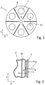
- the second contact element 2 in the example shown has an opening 7, preferably a plurality of openings 7.
- the first surface 4 of the second contact element 2 in the example shown has a plurality of projecting regions 8.
- the projecting regions 8 are advantageously designed as beads 9.
- the second metal foil 3 and the projecting regions 8 are advantageously oriented to one another in such a way that they cross one another.
- the second contact element 2 has a thickness of 0.3 mm.
- the projecting areas 8 protrude by 0.4 mm compared to the first surface.
- the second metal foil 3 has a bent region 10.
- the second metal foil 3 rests in the region of the bend 11 on the projecting region 9 of the first surface 4 of the second contact element 2.
- the thickness of the second metal foil 3 is preferably 0.01 mm.
- FIG. 3 corresponding section line 12 in Fig. 2 shown schematically.
- the second metal foil 3 and the second contact element 2 are each welded with a single-mode fiber laser with a wavelength of 1070 nm.
- a single-mode fiber laser with a wavelength of 1070 nm.
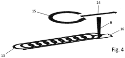
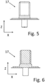
- the laser can also be used in the context of the method according to the invention to weld a pole element 17 to the second contact element 2.
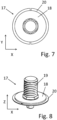
- the pole element 17 has a sealing surface 18. It serves to provide a pole of the accumulator, which in the example shown expediently has a thread 19.
- the pole element 17 with its sealing surface 18 partially covers the beads 9 along which the weld seams between the second contact element 2 and the second metal foil 3 are made.
- connection area 20 surrounds the sealing surface 18.
- the laser power is expediently increased to 800 W, for example.
- the focal length of the focusing optics used in the exemplary embodiment is 330 mm.
- the feed movement 14 of the laser beam is also superimposed by an oscillating movement 15 during the exemplary welding of the pole element.
- the frequency of the circular oscillating movement is 800 Hz, for example, and the amplitude is 0.2 mm.
- the feed speed can be 100 mm/s, for example.
- the pole element 17 is advantageously made of the same material as the second contact element 2, preferably copper.
- the unit thus produced from the electrode coil 1 and the second contact element 2 with the welded pole element 17 can now be introduced into a cup-shaped housing part 21.
- a first edge region of a first metal foil 23 of a first electrode of the electrode coil 1 can be glued to the base 22 of the housing part 21.
- sections of the first edge region of the first metal foil 23 can be bent, in particular by 90° as shown, in order to enable a surface bond between the metal foil 23 and the base 22 of the housing part 21.
- Fig. 10 an alternative embodiment is shown in which, during the manufacture of the battery shown, the first edge region of the first metal foil 23 is not glued directly to the base 22 of the housing part 21, but is first welded to a first contact element 25.
- the first contact element 25 is in turn glued to the base 22 of the housing part 21.
- the welding of the first contact element 25 to the first edge region of the first metal foil 23 can be carried out analogously to the welding of the second contact element 2 to the second metal foil 3 described above.
- the first contact element 25 can have corresponding projecting regions 8 designed as beads 9, analogously to the second contact element 2 described above, as is shown by way of example in Figure 10 is shown.
Landscapes
- Chemical & Material Sciences (AREA)
- Chemical Kinetics & Catalysis (AREA)
- Electrochemistry (AREA)
- General Chemical & Material Sciences (AREA)
- Engineering & Computer Science (AREA)
- Manufacturing & Machinery (AREA)
- Connection Of Batteries Or Terminals (AREA)
Abstract
Die Erfindung betrifft ein Verfahren zur Herstellung eines Akkumulators, wobei Metallfolien (3, 23), welche Elektroden des Akkumulators kontaktieren, gemeinsam mit den Elektroden des Akkumulators derart zu einem, zumindest im Wesentlichen, zylindrischen, insbesondere kreiszylindrischen Elektrodenwickel (1) aufgewickelt werden, dass an einer der beiden sich gegenüberliegenden Stirnseiten des Elektrodenwickels (1) ein erster Randbereich einer ersten Metallfolie (23) zur Kontaktierung einer ersten Elektrode gegenüber den anderen schichtförmigen Bestandteilen des Elektrodenwickels (1) vorsteht. Der Elektrodenwickel (1) wird in ein becherförmiges Gehäuseteil (21) mit einem Boden (22) eingebracht und zur Kontaktierung der ersten Elektrode des Akkumulators der erste Randbereich der ersten Metallfolie (23) der ersten Elektrode und/oder ein mit dem ersten Randbereich elektrisch leitend verbundenes erstes Kontaktelement mit dem Boden (22) des Gehäuseteils (21) verklebt.

Description
Die Erfindung betrifft ein Verfahren zur Herstellung eines Akkumulators, insbesondere ein Verfahren zur Herstellung einer Elektrodenableitung eines Akkumulators, und einen nach dem erfindungsgemäßen Verfahren herstellbaren Akkumulator.The invention relates to a method for producing a rechargeable battery, in particular a method for producing an electrode lead of a rechargeable battery, and a rechargeable battery that can be produced by the method according to the invention.
Bei Akkumulatoren der in Rede stehenden Art sind die Metallfolien, welche insbesondere die Anode und/oder die Kathode des Akkumulators kontaktieren, gemeinsam mit anderen flächigen Bestandteilen des Akkumulators, wie insbesondere den Elektroden des Akkumulators, vorzugsweise spiralförmig, zu einem Elektrodenwickel aufgewickelt.In accumulators of the type in question, the metal foils, which in particular contact the anode and/or the cathode of the accumulator, are wound together with other flat components of the accumulator, such as in particular the electrodes of the accumulator, preferably in a spiral shape, to form an electrode coil.
Derartige Akkumulatoren können dadurch hergestellt werden, dass die Elektrodenwickel in becherförmige Gehäuseteile eingebracht werden. Der becherförmige Gehäuseteil kann mit einem Deckel verschlossen werden, der gegenüber dem Gehäuseteil elektrisch isoliert sein kann. Durch den Deckel hindurch kann ein Pol geführt werden, der mit einer der Metallfolien des Elektrodenwickels elektrisch kontaktiert wird. Die andere Metallfolie des Elektrodenwickels wird mit dem Becher elektrisch kontaktiert, der so den zweiten Pol des resultierenden Akkumulators bildet.Such accumulators can be manufactured by placing the electrode windings in cup-shaped housing parts. The cup-shaped housing part can be closed with a lid, which can be electrically insulated from the housing part. A pole can be led through the lid, which is electrically contacted with one of the metal foils of the electrode winding. The other metal foil of the electrode winding is electrically contacted with the cup, which thus forms the second pole of the resulting accumulator.
Aus der
Ein Akkumulator mit einem günstigeren Bauraumbedarf lässt sich herstellen, indem, wie beispielsweise in der
Aufgabe der Erfindung ist es daher, ein Verfahren zur Herstellung eines Akkumulators und einen Akkumulator zur Verfügung zu stellen, bei denen die vorgenannten Nachteile nicht oder zumindest im geminderten Umfang auftreten.The object of the invention is therefore to provide a method for producing an accumulator and an accumulator in which the aforementioned disadvantages do not occur or at least occur to a reduced extent.
Die Aufgabe wird gelöst durch ein Verfahren einen Akkumulator mit den Merkmalen der unabhängigen Ansprüche. Die Merkmale der abhängigen Ansprüche betreffen vorteilhafte Ausführungsformen.The object is achieved by a method for an accumulator having the features of the independent claims. The features of the dependent claims relate to advantageous embodiments.
Das Verfahren zur Herstellung des Akkumulators sieht vor, dass Metallfolien, welche die Elektroden des Akkumulators kontaktieren, gemeinsam mit den Elektroden des Akkumulators derart zu einem, zumindest im Wesentlichen, zylindrischen, insbesondere kreiszylindrischen, Elektrodenwickel aufgewickelt werden, dass an einer der beiden sich gegenüberliegenden Stirnseiten des Elektrodenwickels ein erster Randbereich einer ersten Metallfolie zur Kontaktierung einer ersten Elektrode gegenüber den anderen schichtförmigen Bestandteilen des Elektrodenwickels vorsteht. Unter den Stirnseiten sind dabei die Seiten des Elektrodenwickels zu verstehen, die den Grundflächen des die geometrische Form des Elektrodenwickels beschreibenden Kreiszylinders entsprechen.The method for producing the accumulator provides that metal foils which contact the electrodes of the accumulator are wound together with the electrodes of the accumulator to form an at least substantially cylindrical, in particular circular cylindrical, electrode coil in such a way that on one of the two opposite end faces of the electrode coil a first edge region of a first metal foil for contacting a first electrode protrudes from the other layered components of the electrode coil. The end faces are understood to mean the sides of the electrode coil that correspond to the base areas of the circular cylinder describing the geometric shape of the electrode coil.
Der Elektrodenwickel wird in ein becherförmiges Gehäuseteil eingebracht und zur Kontaktierung der ersten Elektrode des Akkumulators wird der erste Randbereich der ersten Metallfolie der ersten Elektrode und/oder ein mit dem ersten Randbereich elektrisch leitend verbundenes erstes Kontaktelement mit dem Boden des Gehäuseteils verklebt. Dabei wird der Elektrodenwickel mit dem vorstehenden ersten Randbereich der ersten Metallfolie und/oder das mit dem ersten Randbereich elektrisch leitend verbundenes erste Kontaktelement insbesondere an den Boden des Gehäuseteils angedrückt.The electrode coil is introduced into a cup-shaped housing part and, in order to contact the first electrode of the accumulator, the first edge region of the first metal foil of the first electrode and/or a first contact element that is electrically conductively connected to the first edge region is glued to the bottom of the housing part. The electrode coil with the protruding first edge region of the first metal foil and/or the first contact element that is electrically conductively connected to the first edge region is pressed in particular onto the bottom of the housing part.
Es hat sich überraschenderweise gezeigt, dass auf diese Weise eine zuverlässige elektrische Verbindung zwischen der ersten Metallfolie bzw. dem ersten Kontaktelement und dem Boden erzielt werden kann. Dabei kommt im Rahmen des Verfahrens zum Herstellen der Verklebung insbesondere ein elektrisch leitfähiger Klebstoff zum Einsatz. Ein derartiger elektrisch leitfähiger Klebstoff hat den Vorteil, dass eine elektrische Verbindung zwischen der ersten Metallfolie bzw. dem ersten Kontaktelement und dem Boden über den Klebstoff zustande kommt. Unter einem elektrisch leitfähigen Klebstoff ist hierbei insbesondere ein dauerhaft elektrisch leitfähiger Klebstoff zu verstehen, also insbesondere auch ein Klebstoff, der nach seinem vollständigen Aushärten eine entsprechende elektrische Leitfähigkeit aufweist.Surprisingly, it has been shown that a reliable electrical connection between the first metal foil or the first contact element and the floor can be achieved in this way. In particular, an electrically conductive adhesive is used in the process for producing the bond. Such an electrically conductive adhesive has the advantage that an electrical connection between the first metal foil or the first contact element and the floor is established via the adhesive. An electrically conductive adhesive is to be understood here in particular as a permanently electrically conductive adhesive, i.e. in particular an adhesive that has a corresponding electrical conductivity after it has completely hardened.
Bei der ersten Elektrode kann es sich insbesondere um die Kathode handeln. Die Metallfolie, die zur Kontaktierung der ersten Elektrode genutzt wird, und insbesondere das erste Kontaktelement, besteht in diesem Fall vorzugsweise aus Aluminium oder einer Aluminiumlegierung. Das Gehäuseteil und insbesondere der Boden des Gehäuseteils besteht in diesem Fall insbesondere ebenfalls aus Aluminium oder einer Aluminiumlegierung.The first electrode can in particular be the cathode. The metal foil used to contact the first electrode, and in particular the first contact element, in this case preferably consists of aluminum or an aluminum alloy. The housing part and in particular the base of the housing part in this case also consists in particular of aluminum or an aluminum alloy.
Bei der ersten Elektrode kann es sich alternativ um die Anode handeln. Die Metallfolie, die zur Kontaktierung der ersten Elektrode genutzt wird, und insbesondere das erste Kontaktelement, besteht in diesem Fall vorzugsweise aus Kupfer oder einer Kupferlegierung. Das Gehäuseteil und insbesondere der Boden des Gehäuseteils besteht in diesem Fall insbesondere aus einem Stahl.The first electrode can alternatively be the anode. The metal foil used to contact the first electrode, and in particular the first contact element, in this case preferably consists of copper or a copper alloy. The housing part and in particular the base of the housing part in this case consists in particular of a steel.
Das Gehäuseteil kann insbesondere tiefgezogen sein. Es hat sich gezeigt, dass mittels des Tiefziehens, das vorzugsweise in mehreren Stufen erfolgt, eine hinreichende Maßhaltigkeit des Gehäuseteils und insbesondere des Bodens erzielt werden kann, um die Verklebung reproduzierbar durchzuführen.The housing part can in particular be deep-drawn. It has been shown that by means of deep-drawing, which preferably takes place in several stages, sufficient dimensional accuracy of the housing part and in particular of the base can be achieved in order to carry out the bonding in a reproducible manner.
Das Verfahren sieht insbesondere vor, dass der Randbereich der ersten Metallfolie vor dem Verkleben des Randbereichs mit dem Boden, zumindest in Teilabschnitten, derart umgebogen wird, dass sich eine flächige Verklebung von zumindest Teilabschnitten des Randbereichs mit dem Boden ergibt. Es hat sich gezeigt, dass die Verklebung des Bodens mit der Metallfolie verbessert werden kann, wenn die Metallfolie und der Boden flächig aneinander anliegen. Dazu kann es sinnvoll sein, wenn der Randbereich oder zumindest Teilabschnitte des Randbereichs umgebogen werden. Der Randbereich bzw. die Teilabschnitte des Randbereichs werden in diesem Zusammenhang insbesondere um, zumindest im Wesentlichen, 90° umgebogen.The method provides in particular that the edge region of the first metal foil is bent over, at least in partial sections, before the edge region is bonded to the floor, in such a way that a surface bonding of at least partial sections of the edge region to the floor is achieved. It has been shown that the bonding of the floor to the metal foil can be improved if the metal foil and the floor lie flat against each other. For this purpose, it can be useful if the edge area or at least sections of the edge area are bent over. In this context, the edge area or sections of the edge area are bent over, at least essentially, by 90°.
Um das Umbiegen von Teilabschnitten zu erleichtern, kann der Randbereich, insbesondere vor dem Umbiegen der Teilbereiche, eingeschnitten werden, sodass Teilabschnitte des Randbereichs erzeugt werden, die unabhängig voneinander umgebogen werden können. Dies kann insbesondere bei einem kreiszylindrischen Elektrodenwickel und einem entsprechenden spiralförmigen Verlauf des von dem Elektrodenwickel hervorstehenden Randbereichs das Umbiegen desselben um ca. 90° signifikant erleichtern. Hierbei kann es vorkommen, dass sich Teilabschnitte, insbesondere benachbarte Teilabschnitte, des Randbereichs nach dem Umbiegen überlappen.In order to facilitate the bending of sections, the edge region can be cut, particularly before the sections are bent, so that sections of the edge region are created that can be bent independently of one another. This can significantly facilitate the bending of the edge region by approximately 90°, particularly in the case of a circular cylindrical electrode coil and a corresponding spiral course of the edge region protruding from the electrode coil. It can happen that sections, particularly adjacent sections, of the edge region overlap after bending.
Alternativ und/oder ergänzend ist es möglich, dass der Randbereich vor dem Verkleben des mit dem Randbereich verbundenen ersten Kontaktelements mit dem Boden mit dem ersten Kontaktelement verschweißt wird. Das Verfahren sieht dann insbesondere vor, dass der Elektrodenwickel mit dem angeschweißten Kontaktelement in das Gehäuseteil zum Zweck des Verklebens eingebracht wird. Das erste Kontaktelement lässt sich signifikant leichter mit dem Randbereich verschweißen, wenn das Verschweißen vor dem Einbringen des Elektrodenwickels das Gehäuseteil erfolgt. Die Verklebung zwischen dem ersten Kontaktelement und dem Boden hingegen kann weitgehend unabhängig davon erfolgen, ob das erste Kontaktelement bereits mit dem Elektrodenwickel verschweißt ist. Von daher ist die Herstellungsreihenfolge, zunächst das erste Kontaktelemente mit dem Elektrodenwickel zu verschweißen und dieses erst dann in das Gehäuseteil einzubringen, um das erste Kontaktelement mit dem Boden zu verkleben, vorteilhaft.Alternatively and/or additionally, it is possible for the edge region to be welded to the first contact element before the first contact element connected to the edge region is glued to the base. The method then provides in particular for the electrode coil with the welded contact element to be introduced into the housing part for the purpose of gluing. The first contact element can be welded to the edge region significantly more easily if the welding takes place before the electrode coil is introduced into the housing part. The bonding between the first contact element and the base, on the other hand, can take place largely independently of whether the first contact element is already welded to the electrode coil. The production sequence of first welding the first contact element to the electrode coil and only then introducing this into the housing part in order to glue the first contact element to the base is therefore advantageous.
Bei dem Akkumulator handelt es sich vorzugsweise um einen Lithium-Ionen-Akkumulator. Lithium-Ionen-Akkumulatoren ermöglichen die Speicherung vergleichsweise große Mengen Energie bei geringem Gewicht und Raumbedarf. Das erfindungsgemäße Verfahren bietet daher insbesondere bei der Herstellung dieser Akkumulatoren einen hohen Mehrwert.The battery is preferably a lithium-ion battery. Lithium-ion batteries enable the storage of comparatively large amounts of energy with low weight and space requirements. The method according to the invention therefore offers high added value, particularly in the production of these accumulators.
Bevorzugt weist der Akkumulator eine, zumindest im Wesentlichen, zylindrische Geometrie auf. Unter einer zumindest im Wesentlichen zylindrischen Geometrie ist insbesondere eine Geometrie zu verstehen, bei der die Hauptabmessungen des Akkumulators eine zylindrische Geometrie bilden. Einzelne Elemente des Akkumulators, beispielsweise die Pole, können hierbei eine von einer strengen Zylinderform abweichende Gestaltung aufweisen. Akkumulatoren mit zylindrischer Geometrie sind als Bauform bereits standardisiert, weshalb regelmäßig ein einfacher Austausch der Akkumulatoren möglich ist.The accumulator preferably has an at least substantially cylindrical geometry. An at least substantially cylindrical geometry is to be understood in particular as a geometry in which the main dimensions of the accumulator form a cylindrical geometry. Individual elements of the accumulator, for example the poles, can have a design that deviates from a strict cylindrical shape. Accumulators with a cylindrical geometry are already standardized as a design, which is why the accumulators can usually be easily replaced.
Der Akkumulator nimmt durch die spiralförmige Aufwicklung insbesondere eine, zumindest im Wesentlichen, kreiszylindrische Form an. Die Achse der spiralförmigen Wicklung entspricht hierbei bevorzugt der Mittelachse des Zylinders. Unter der Achse ist hierbei insbesondere das linienförmige Zentrum der spiralförmigen Wicklung zu verstehen. Eine physische Achse im Sinne eines entsprechenden Bauteils kann vorhanden sein, ist jedoch nicht zwingend notwendig.Due to the spiral winding, the accumulator takes on a circular-cylindrical shape, at least essentially. The axis of the spiral winding preferably corresponds to the central axis of the cylinder. The axis here is understood to mean in particular the linear center of the spiral winding. A physical axis in the sense of a corresponding component can be present, but is not absolutely necessary.
Das Verfahren kann vorsehen, dass zur Kontaktierung einer zweiten Elektrode des Akkumulators eine zweite Metallfolie zur Kontaktierung der zweiten Elektrode mit einem zweiten Kontaktelement verschweißt wird. Hierbei ist das Kontaktelement insbesondere flächig und rechtwinklig zur Achse des Elektrodenwickels orientiert. Dabei dient die Ordnungszahl "zweiten" lediglich der sprachlichen Unterscheidung dieses Kontaktelements von dem ersten Kontaktelement. Keinesfalls setzt das zweite Kontaktelement zwingend das Vorhandensein des optionalen ersten Kontaktelements voraus.The method can provide that a second metal foil is welded to a second contact element to contact a second electrode of the accumulator. In this case, the contact element is particularly flat and oriented at right angles to the axis of the electrode coil. The ordinal number "second" is used only to linguistically distinguish this contact element from the first contact element. Under no circumstances does the second contact element necessarily require the presence of the optional first contact element.
Es ist vorteilhaft, wenn die zweite Metallfolie, insbesondere der mit dem Boden dem zweiten Kontaktelement zu verbindende Bereich der zweiten Metallfolie, gegenüber den anderen flächigen bzw. schichtförmigen Bestandteilen des Akkumulators, wie beispielsweise der Kathode, der Anode oder einer weiteren Metallfolie, in Richtung des zweiten Kontaktelements, vorzugsweise in Richtung der Achse des Elektrodenwickels, vorsteht.It is advantageous if the second metal foil, in particular the area of the second metal foil to be connected to the bottom of the second contact element, protrudes in the direction of the second contact element, preferably in the direction of the axis of the electrode winding, relative to the other flat or layered components of the accumulator, such as the cathode, the anode or another metal foil.
Das Verfahren kann vorsehen, dass zum Verschweißen des ersten Randbereichs mit dem ersten Kontaktelement und/oder zum Verschweißen des zweiten Randbereichs mit dem zweiten Kontaktelement der erste und/oder der zweite Randbereich mit einer rechtwinklig zur jeweiligen Metallfolie orientierten ersten Fläche des jeweiligen Kontaktelements in Kontakt gebracht und durch die Beaufschlagung einer von der ersten Fläche des jeweiligen Kontaktelements abgewandten zweiten Fläche des jeweiligen Kontaktelements mit einem Laserstrahl mit dem jeweiligen Kontaktelement verschweißt wird.The method can provide that, in order to weld the first edge region to the first contact element and/or to weld the second edge region to the second contact element, the first and/or the second edge region is brought into contact with a first surface of the respective contact element oriented at right angles to the respective metal foil and is welded to the respective contact element by applying a laser beam to a second surface of the respective contact element facing away from the first surface of the respective contact element.
Es ist vorteilhaft, wenn zum Verschweißen des ersten Randbereichs mit dem ersten Kontaktelement und/oder zum Verschweißen des zweiten Randbereichs mit dem zweiten Kontaktelement ein Bereich der ersten Metallfolie und/oder ein Bereich der zweiten Metallfolie umgebogen wird. Das Umbiegen des Bereichs der jeweiligen Metallfolie kann zweckmäßigerweise vor und/oder während dem Aufwickeln der Metallfolie erfolgen. Es kann eine Vielzahl von Biegeverfahren zum Einsatz kommen, bevorzugt handelt es sich um ein Bördelverfahren. Das Verschwei-ßen der Metallfolie mit dem ersten Kontaktelement und/oder dem zweiten Kontaktelement erfolgt dann vorzugsweise im Bereich der erzeugten Biegung. Hierdurch wird die Anlagefläche der Metallfolie am ersten Kontaktelement und/oder am zweiten Kontaktelement vergrößert, was sich positiv auf die Verschweißung auswirkt. Bei der Biegung kann es sich beispielsweise um eine Umbiegung um 180° handeln. Es sind jedoch auch andere Gestaltungen der Biegung denkbar, insbesondere kann auch ein mehrfaches Umbiegen erfolgen. Es versteht sich in diesem Zusammenhang, dass unter dem Randbereich, der mit dem Kontaktelement verbunden wird, im Zweifel nicht der Randbereich der ursprünglichen Metallfolie vor dem Umbiegen zu verstehen ist, sondern vielmehr der Teil der Metallfolie, der nach dem Umbiegen der Metallfolie den durch das Umbiegen erzeugten neuen Rand der Metallfolie bildet.It is advantageous if a region of the first metal foil and/or a region of the second metal foil is bent over in order to weld the first edge region to the first contact element and/or to weld the second edge region to the second contact element. The bending of the region of the respective metal foil can expediently take place before and/or during the winding of the metal foil. A variety of bending methods can be used, preferably a flanging method. The welding of the metal foil to the first contact element and/or the second contact element then preferably takes place in the region of the bend created. This increases the contact surface of the metal foil on the first contact element and/or the second contact element, which has a positive effect on the welding. The bend can be a bend of 180°, for example. However, other designs of the bend are also conceivable, in particular multiple bending can also take place. In this context, it is understood that the edge region which is connected to the contact element does not, in case of doubt, mean the edge region of the original metal foil before bending, but rather the part of the metal foil which, after the metal foil has been bent, forms the new edge of the metal foil created by the bending.
Hierbei ist es vorteilhaft, wenn die erste Metallfolie und/oder die zweite Metallfolie gegenüber den anderen schichtförmigen Bestandteilen des Akkumulators wenigstens 1 mm, vorzugsweise wenigstens 2 mm, und/oder höchstens 8 mm, vorzugsweise höchstens 6 mm, vorsteht. Dieser vorstehende Bereich der Metallfolie ermöglicht es, die Metallfolie mit dem erfindungsgemäßen Verfahren zu kontaktieren, wobei das Risiko, andere schichtförmige Bestandteile des Akkumulators durch die Verschweißung zu beeinträchtigen und/oder zu beschädigen, ausgeschlossen oder zumindest gesenkt wird.It is advantageous if the first metal foil and/or the second metal foil protrudes from the other layered components of the accumulator by at least 1 mm, preferably at least 2 mm, and/or at most 8 mm, preferably at most 6 mm. This protruding area of the metal foil enables It is possible to contact the metal foil using the method according to the invention, whereby the risk of impairing and/or damaging other layered components of the accumulator by the welding is excluded or at least reduced.
Die Dicke des ersten und/oder zweiten Kontaktelements beträgt bevorzugt wenigstens 0,05 mm, besonders bevorzugt wenigstens 0,15 mm, und/oder bevorzugt höchstens 1,5 mm, besonders bevorzugt höchstens 0,6 mm.The thickness of the first and/or second contact element is preferably at least 0.05 mm, particularly preferably at least 0.15 mm, and/or preferably at most 1.5 mm, particularly preferably at most 0.6 mm.
Es ist vorteilhaft, wenn die erste und/oder zweite Metallfolie an einen vorspringenden Bereich der ersten Fläche des ersten Kontaktelements und/oder der ersten Fläche des zweiten angeschweißt wird. Ein derartiger vorspringender Bereich an dem ersten Kontaktelement und/oder dem zweiten Kontaktelement ermöglicht es, einen definierten lokalen Kontakt zwischen der Metallfolie und dem ersten Kontaktelement und/oder dem zweiten Kontaktelement herzustellen, an dem die Schwei-ßung erfolgt. Dabei weist das jeweilige Kontaktelement bevorzugt an seiner dem vorspringenden Bereich gegenüberliegenden Fläche einen zurückspringenden Bereich auf. Dieser zurückspringende Bereich ist bevorzugt hinsichtlich seiner Form komplementär zu dem vorspringenden Bereich gestaltet. dabei können der vorspringende Bereich und der zurückspringende Bereich gemeinsam als Sicke in dem jeweiligen Kontaktelement ausgeführt sein. Diese Gestaltung hat den Vorteil, dass sie in einfacher Weise herzustellen ist und dazu führt, dass die Dicke des jeweiligen Kontaktelements im betroffenen Bereich zumindest annähernd konstant bleibt.It is advantageous if the first and/or second metal foil is welded to a projecting region of the first surface of the first contact element and/or the first surface of the second. Such a projecting region on the first contact element and/or the second contact element makes it possible to establish a defined local contact between the metal foil and the first contact element and/or the second contact element at which the welding takes place. The respective contact element preferably has a recessed region on its surface opposite the projecting region. This recessed region is preferably designed to be complementary to the projecting region in terms of its shape. The projecting region and the recessed region can be designed together as a bead in the respective contact element. This design has the advantage that it is easy to produce and means that the thickness of the respective contact element in the affected region remains at least approximately constant.
Der vorspringende Bereich springt bevorzugt um wenigstens 0,3 mm, besonders bevorzugt um wenigstens 0,5 mm, und/oder bevorzugt um höchstens 2 mm, besonders bevorzugt um höchstens 1,5 mm, gegenüber der umliegenden ersten Fläche des jeweiligen Kontaktelements vor.The projecting region preferably projects by at least 0.3 mm, particularly preferably by at least 0.5 mm, and/or preferably by at most 2 mm, particularly preferably by at most 1.5 mm, relative to the surrounding first surface of the respective contact element.
Der jeweilige vorspringende Bereich bzw. die jeweilige Sicke ist bevorzugt linienförmig gestaltet und weist eine Breite von bevorzugt wenigstens 0,5 mm, besonders bevorzugt von wenigstens 1 mm, und/oder bevorzugt von höchstens 5 mm, besonders bevorzugt von höchstens 3 mm, auf. Dabei kreuzt sich in der Ebene, in der die jeweilige Metallfolie mit einem vorspringenden Bereich in Kontakt gelangt, der vorspringende Bereich bevorzugt mit der Metallfolie. Bei gefalteter und/oder aufgewickelten Bauweise des Akkumulators ergeben sich so eine Mehrzahl einzelner Berührungspunkte zwischen dem Randbereich der jeweiligen Metallfolie und dem jeweiligen Kontaktelement, was zu einer zuverlässigen Verschweißung an diesen Stellen führt.The respective projecting area or the respective bead is preferably linear and has a width of preferably at least 0.5 mm, particularly preferably at least 1 mm, and/or preferably at most 5 mm, particularly preferably at most 3 mm. In this case, in the plane in which the respective metal foil comes into contact with a protruding area, the protruding area preferably with the metal foil. If the accumulator is folded and/or wound up, this results in a plurality of individual contact points between the edge area of the respective metal foil and the respective contact element, which leads to reliable welding at these points.
Die erste Metallfolie und/oder die zweite Metallfolie weist bevorzugt eine Dicke von wenigstens 0,001 mm, besonders bevorzugt von wenigstens 0,005 mm, und/oder bevorzugt von höchstens 0,02 mm, besonders bevorzugt von höchstens 0,012 mm auf.The first metal foil and/or the second metal foil preferably has a thickness of at least 0.001 mm, particularly preferably of at least 0.005 mm, and/or preferably of at most 0.02 mm, particularly preferably of at most 0.012 mm.
Es ist vorteilhaft, wenn ein Polelement zur Bildung des Pols des Akkumulators mit dem zweiten Kontaktelement verbunden, insbesondere verschweißt, wird. Auf diese Weise kann das zweite Kontaktelement in seiner Geometrie, die bevorzugt flächig bzw. plättchenförmig ist, unabhängig von der Form des Pols gestaltet werden. Dies ist insbesondere deswegen von Vorteil, da die Form des Pols Beschränkungen unterliegt, die regelmäßig von der geplanten Verwendung des hergestellten Akkumulators und/oder technischen Standards abhängen.It is advantageous if a pole element is connected, in particular welded, to the second contact element to form the pole of the accumulator. In this way, the geometry of the second contact element, which is preferably flat or plate-shaped, can be designed independently of the shape of the pole. This is particularly advantageous because the shape of the pole is subject to restrictions that regularly depend on the intended use of the accumulator produced and/or technical standards.
Die Verbindung des Polelements mit dem zweiten Kontaktelement kann beispielsweise durch eine Überlappungs-Verschweißung oder eine Kehlnaht-Verschweißung erfolgen.The pole element can be connected to the second contact element, for example, by means of an overlap weld or a fillet weld.
In vorteilhafter Weise kann die Verbindung des Polelements mit dem zweiten Kontaktelement mit demselben Laser erfolgen wie die Verschweißung der Metallfolie mit dem zweiten Kontaktelement. Dies ermöglicht es beispielsweise, die Verschweißung der Metallfolie mit dem zweiten Kontaktelement und die Verschweißung des Polelements mit dem Kontaktelement in der gleichen Vorrichtung vorzunehmen, was die Herstellung des Akkumulators vereinfacht.Advantageously, the connection of the pole element to the second contact element can be carried out with the same laser as the welding of the metal foil to the second contact element. This makes it possible, for example, to weld the metal foil to the second contact element and to weld the pole element to the contact element in the same device, which simplifies the manufacture of the accumulator.
Das Polelement kann beispielsweise ein Gewinde zur Bildung des Pols des Akkumulators aufweisen. Mit einem derartigen Gewinde kann der Akkumulator zuverlässig elektrisch mit der von dem Akkumulator versorgten Einrichtung verbunden werden.The pole element can, for example, have a thread to form the pole of the accumulator. With such a thread, the accumulator can be reliably electrically connected to the device supplied by the accumulator. become.
Es ist vorteilhaft, wenn das Polelement eine Dichtfläche aufweist. Die Dichtfläche dient insbesondere der Verbindung des Polelements mit dem Gehäuse des Akkumulators. Auf diese Weise kann ein dichter und vorzugsweise elektrisch isolierter Akkumulator geschaffen werden, wobei das Polelement zum Zwecke der elektrischen Kontaktierung des Akkumulators zugänglich bleibt. Die elektrische Isolierung des Akkumulators kann zwischen dem Gehäuseteil und einem Deckel des Gehäuses und/oder dem Polelement und einem Deckel des Gehäuses angeordnet sein.It is advantageous if the pole element has a sealing surface. The sealing surface serves in particular to connect the pole element to the housing of the accumulator. In this way, a sealed and preferably electrically insulated accumulator can be created, with the pole element remaining accessible for the purpose of electrically contacting the accumulator. The electrical insulation of the accumulator can be arranged between the housing part and a cover of the housing and/or the pole element and a cover of the housing.
Bevorzugt überdeckt das Polelement - zumindest teilweise - Schweißnähte zum Verbinden der zweiten Metallfolie mit dem zweiten Kontaktelement. Eine solche Bauweise des Akkumulators lässt sich insbesondere erzeugen, indem zunächst die zweite Metallfolie mit dem zweiten Kontaktelement, und danach das zweite Kontaktelement mit dem Polelement verschweißt wird. Auf diese Weise kann das Polelement und insbesondere die Dichtfläche des Polelements in einem Bereich auf der zweiten Fläche des zweiten Kontaktelements angeordnet werden, der ebenfalls zum Verschweißen des zweiten Kontaktelements mit der Metallfolie genutzt wird.The pole element preferably covers - at least partially - weld seams for connecting the second metal foil to the second contact element. Such a design of the accumulator can be produced in particular by first welding the second metal foil to the second contact element and then the second contact element to the pole element. In this way, the pole element and in particular the sealing surface of the pole element can be arranged in an area on the second surface of the second contact element, which is also used for welding the second contact element to the metal foil.
Es ist vorteilhaft, wenn das Polelement beim Verschweißen mit dem zweiten Kontaktelement an das zweite Kontaktelement angepresst wird. Es hat sich gezeigt, dass auf diese Weise die Bildung von Spalten, zu denen es zwischen dem Polelement und dem zweiten Kontaktelement kommen kann, wirksam verhindert werden kann.It is advantageous if the pole element is pressed against the second contact element when it is welded to the second contact element. It has been shown that in this way the formation of gaps that can occur between the pole element and the second contact element can be effectively prevented.
Bevorzugt handelt es sich bei dem Laser, mit dem die erste Metallfolie mit dem ersten Kontaktelement, die zweite Metallfolie mit dem zweiten Kontaktelement und/oder das zweite Kontaktelement mit dem Polelement verschweißt wird, um einen Faserlaser. Faserlaser, die auch als Faser bezeichnet werden, nutzen den dotierten Kern einer Glasfaser als aktives Medium. Der Vorteil der Faserlaser ist, dass durch die mögliche große Länge der laseraktiven Faser eine hohe Verstärkung möglich ist.The laser used to weld the first metal foil to the first contact element, the second metal foil to the second contact element and/or the second contact element to the pole element is preferably a fiber laser. Fiber lasers, also referred to as fibers, use the doped core of a glass fiber as an active medium. The advantage of fiber lasers is that the possible great length of the laser-active fiber enables high amplification.
Der Laser, mit dem die erste Metallfolie mit dem ersten Kontaktelement, die zweite Metallfolie mit dem zweiten Kontaktelement und/oder das zweite Kontaktelement mit dem Polelement verschweißt wird, wird hierbei vorzugsweise kontinuierlich, also als Dauerstrich-Laser, betrieben. Bei diesem Betrieb wird der Laserstrahl insbesondere nicht gepulst. Es hat sich gezeigt, dass sich mit dem kontinuierlichen Betrieb des Lasers besonders gute Ergebnisse hinsichtlich der Verschweißung erzielen lassen.The laser used to connect the first metal foil with the first contact element, the second Metal foil is welded to the second contact element and/or the second contact element is welded to the pole element, preferably operated continuously, i.e. as a continuous wave laser. In this mode, the laser beam is not pulsed. It has been shown that particularly good results in terms of welding can be achieved with continuous operation of the laser.
Bevorzugt beträgt die mittlere Leistung, insbesondere die konstante Leistung des Lasers im kontinuierlichen Betrieb des Lasers beim Verschweißen der ersten Metallfolie mit dem ersten Kontaktelement und/oder der zweiten Metallfolie mit dem zweiten Kontaktelement wenigstens 100 W, besonders bevorzugt wenigstens 200 W und/oder höchstens 700 W, besonders bevorzugt höchstens 500 W. Bei diesen Leistungen konnten besonders gute Ergebnisse hinsichtlich der Verschweißung erzielt werden.Preferably, the average power, in particular the constant power of the laser in continuous operation of the laser when welding the first metal foil to the first contact element and/or the second metal foil to the second contact element is at least 100 W, particularly preferably at least 200 W and/or at most 700 W, particularly preferably at most 500 W. At these powers, particularly good results with regard to welding could be achieved.
Wenn mit dem Laser das Polelement mit dem zweiten Kontaktelement verschweißt wird, so ist es sinnvoll, die Laserleistung zu diesem Zweck zu erhöhen. Beim Verschweißen des Polelements mit dem zweiten Kontaktelement beträgt die mittlere Leistung, insbesondere die konstante Leistung des Lasers im kontinuierlichen Betrieb bevorzugt wenigstens 500 W, besonders bevorzugt wenigstens 700 W, und/oder bevorzugt höchstens 1500 W, besonders bevorzugt höchstens 1000 W.If the pole element is welded to the second contact element using the laser, it is advisable to increase the laser power for this purpose. When welding the pole element to the second contact element, the average power, in particular the constant power of the laser in continuous operation is preferably at least 500 W, particularly preferably at least 700 W, and/or preferably at most 1500 W, particularly preferably at most 1000 W.
Die Wellenlänge des Lasers, mit dem die erste Metallfolie mit dem ersten Kontaktelement, die zweite Metallfolie mit dem zweiten Kontaktelement und/oder das zweite Kontaktelement mit dem Polelement verschweißt wird, beträgt vorzugsweise 1070 nm. Mit einem Laser dieser Wellenlänge können gute Ergebnisse erzielt werden, zudem sind Laser dieser Wellenlänge kommerziell verfügbar.The wavelength of the laser used to weld the first metal foil to the first contact element, the second metal foil to the second contact element and/or the second contact element to the pole element is preferably 1070 nm. Good results can be achieved with a laser of this wavelength, and lasers of this wavelength are also commercially available.
Bevorzugt wird ein Singlemode-Laser zum Verschweißen der ersten Metallfolie mit dem ersten Kontaktelement, der zweiten Metallfolie mit dem zweiten Kontaktelement und/oder des zweite Kontaktelements mit dem Polelement verwendet. Bei diesen Lasern werden lediglich Wellen einer einzigen gewünschten Mode verstärkt, während andere Moden unterdrückt werden. Derartige Laser weisen im Idealfall lediglich eine einzige, schmale Spektrallinie auf. Hierdurch erreicht der Laserstrahl eine hohe optische Qualität, was sich insbesondere auf dessen gute Fokussierbarkeit auswirkt.Preferably, a single-mode laser is used to weld the first metal foil to the first contact element, the second metal foil to the second contact element and/or the second contact element to the pole element. With these lasers, only waves of a single desired mode are amplified, while other modes are suppressed. Such lasers ideally have only a single, narrow spectral line. This means that the laser beam reaches a high optical quality, which particularly affects its good focusability.
Bevorzugt wird der Laser, mit dem die erste Metallfolie mit dem ersten Kontaktelement, die zweite Metallfolie mit dem zweiten Kontaktelement und/oder das zweite Kontaktelement mit dem Polelement verschweißt wird, mit einer Fokussieroptik fokussiert. Eine solche Fokussieroptik ermöglicht die Bündelung des Laserstrahls. Es hat sich gezeigt, dass für das erfindungsgemäße Verfahren Fokussieroptiken mit einer Brennweite von wenigstens 10 mm, vorzugsweise wenigstens 100 mm und/oder höchstens 5000 mm, vorzugsweise höchstens 500 mm, zu besonders guten Ergebnissen führen. Dies gilt sowohl für die Verschweißung der jeweiligen Metallfolie mit dem entsprechenden Kontaktelement, als auch für die Verschweißung des zweiten Kontaktelements mit dem Polelement.Preferably, the laser used to weld the first metal foil to the first contact element, the second metal foil to the second contact element and/or the second contact element to the pole element is focused using a focusing optic. Such a focusing optic enables the laser beam to be bundled. It has been shown that for the method according to the invention, focusing optics with a focal length of at least 10 mm, preferably at least 100 mm and/or at most 5000 mm, preferably at most 500 mm, lead to particularly good results. This applies both to the welding of the respective metal foil to the corresponding contact element and to the welding of the second contact element to the pole element.
Bevorzugt weist der verwendete Laserstrahl, mit dem die erste Metallfolie mit dem ersten Kontaktelement, die zweite Metallfolie mit dem zweiten Kontaktelement und/oder das zweite Kontaktelement mit dem Polelement verschweißt wird, einen Fokusdurchmesser von wenigstens 1 µm, vorzugsweise wenigstens 10 µm und/oder höchstens 500 µm, vorzugsweise höchstens 50 µm auf. Es hat sich gezeigt, dass sich mit diesen Fokusdurchmessern eine besonders gute Verschweißung der jeweiligen Metallfolie und/oder des Polelements mit dem entsprechenden Kontaktelement erzielen lässt. Dies gilt sowohl für die Verschweißung der jeweiligen Metallfolie mit dem entsprechenden Kontaktelement, als auch für die Verschweißung des zweiten Kontaktelements mit dem Polelement.Preferably, the laser beam used to weld the first metal foil to the first contact element, the second metal foil to the second contact element and/or the second contact element to the pole element has a focus diameter of at least 1 µm, preferably at least 10 µm and/or at most 500 µm, preferably at most 50 µm. It has been shown that with these focus diameters, a particularly good welding of the respective metal foil and/or the pole element to the corresponding contact element can be achieved. This applies both to the welding of the respective metal foil to the corresponding contact element and to the welding of the second contact element to the pole element.
Bevorzugt wird der Auftreffpunkt des Lasers auf dem jeweiligen Kontaktelement, bei dem es sich vorzugsweise um den Fokus des Laserstrahls handelt, entlang einer Bewegungsbahn bewegt, die sich aus der Überlagerung einer Vorschubbewegung und einer oszillierenden Bewegung ergibt. Beim Verschweißen des zweiten Kontaktelements mit dem Polelement gilt dies gegebenenfalls für den Auftreffpunkt des Laserstrahls auf dem Polelement.Preferably, the point of impact of the laser on the respective contact element, which is preferably the focus of the laser beam, is moved along a movement path that results from the superposition of a feed movement and an oscillating movement. When welding the second contact element to the pole element, this may apply to the point of impact of the laser beam on the pole element.
Bei der Vorschubbewegung handelt es sich um die Bewegung, mit der der Auftreffpunkt des Lasers dem Verlauf der herzustellenden Schweißnaht folgt. Die Geschwindigkeit, mit der der Auftreffpunkt sich auf der Oberfläche des jeweiligen Kontaktelements bzw. gegebenenfalls des Polelements entlang der Schweißnaht bewegt, wird in diesem Zusammenhang als Vorschubgeschwindigkeit bezeichnet. Die Vorschubgeschwindigkeit beträgt vorzugsweise wenigstens 10 mm/s, vorzugsweise wenigstens 70 mm/s, und/oder höchstens 200 mm/s, vorzugsweise höchstens 150 mm/s. Es hat sich gezeigt, dass sich mit diesen Vorschubgeschwindigkeiten eine vergleichsweise schnelle Herstellung der Schweißnähte mit gleichzeitig hoher Qualität erzielen lässt. Es versteht sich, dass - im Fall der Überlagerung der Vorschubbewegung mit einer oszillierenden Bewegung - nicht die absolute Geschwindigkeit der resultierenden Bewegung in Vorschubrichtung, sondern eine mittlere Bewegungsgeschwindigkeit in Vorschubrichtung als Vorschubgeschwindigkeit anzusehen ist.The feed movement is the movement with which the point of impact of the laser follows the course of the weld seam to be produced. The speed, The speed at which the point of impact moves on the surface of the respective contact element or, if applicable, the pole element along the weld seam is referred to in this context as the feed rate. The feed rate is preferably at least 10 mm/s, preferably at least 70 mm/s, and/or at most 200 mm/s, preferably at most 150 mm/s. It has been shown that these feed rates enable the weld seams to be produced comparatively quickly while at the same time maintaining high quality. It is understood that - in the case of superimposing the feed movement with an oscillating movement - the feed rate is not the absolute speed of the resulting movement in the feed direction, but an average movement speed in the feed direction.
Die oszillierende Bewegung, die vorzugsweise von der Vorschubbewegung überlagert wird, weist vorzugsweise eine Frequenz von wenigstens 100 Hz, vorzugsweise wenigstens 500Hz und/oder höchstens 5000 Hz, vorzugsweise höchstens 1500 Hz auf. Die Amplitude der oszillierenden Bewegung beträgt vorzugsweise wenigstens 0,02 mm, vorzugsweise wenigstens 0,1mm, und/oder höchstens 0,5 mm, vorzugsweise höchstens 1mm. Es hat sich gezeigt, dass eine örtliche Leistungsmodulation realisiert werden kann, die eine besonders gute Schmelzbadkontrolle ermöglicht.The oscillating movement, which is preferably superimposed on the feed movement, preferably has a frequency of at least 100 Hz, preferably at least 500 Hz and/or at most 5000 Hz, preferably at most 1500 Hz. The amplitude of the oscillating movement is preferably at least 0.02 mm, preferably at least 0.1 mm, and/or at most 0.5 mm, preferably at most 1 mm. It has been shown that a local power modulation can be realized, which enables particularly good melt pool control.
Es kann sich bevorzugt um eine kreisförmige oszillierende Bewegung handeln. In diesem Fall entspricht der Radius des durch die oszillierende Bewegung beschriebenen Kreises der Amplitude im Hinblick auf die vorstehend angegebenen Werte. Im Fall komplexer oszillierender Bewegungen, wie beispielsweise einer elliptischen oszillierenden Bewegung, ist entsprechend eine mittlere Amplitude als Amplitude anzusehen.It can preferably be a circular oscillating movement. In this case, the radius of the circle described by the oscillating movement corresponds to the amplitude with respect to the values given above. In the case of complex oscillating movements, such as an elliptical oscillating movement, an average amplitude is to be regarded as the amplitude.
Das Verfahren kann insbesondere vorsehen, dass die Leistung des Laserstrahls während des Verschweißens der Metallfolie dem ersten Kontaktelement und/oder dem zweiten Kontaktelement variiert wird. Insbesondere kann die Leistung des Laserstrahls bei zu Beginn der Herstellung einer Schweißnaht gesteigert und/oder zum Ende der Herstellung einer Schweißnaht abgesenkt wird. Das Steigern und/oder Absenken der Leistung kann kontinuierlich, beispielsweise in Gestalt einer Rampe, erfolgen. Es hat sich gezeigt, dass dadurch insbesondere eine Bildung von Löchern im Kontaktelement während des Schweißens vermieden werden kann.The method can in particular provide that the power of the laser beam is varied during the welding of the metal foil to the first contact element and/or the second contact element. In particular, the power of the laser beam can be increased at the beginning of the production of a weld seam and/or reduced at the end of the production of a weld seam. The increase and/or lowering the power can be done continuously, for example in the form of a ramp. It has been shown that this can prevent the formation of holes in the contact element during welding.
Für das Herstellen des Akkumulators ist es vorteilhaft, wenn das Verschweißen der Metallfolien mit dem jeweiligen Kontaktelement und/oder das Umbiegen der Metallfolien erfolgt, bevor der Elektrodenwickel in das Gehäuseteil eingebracht wird und/oder bevor der erste Randbereich und/oder das erste Kontaktelement vor dem Einbringen in das Gehäuseteil mit, insbesondere leitfähigem, Klebstoff versehen wird. Alternativ und/oder ergänzend kann der Klebstoff auch vor dem Einbringen des Elektrodenwickels in das Gehäuseteil in das Gehäuseteil eingebracht werden. Hierbei wird insbesondere der Boden des Gehäuseteils mit dem Klebstoff versehen, bevor der Elektrodenwickel in das Gehäuseteil eingebracht wird.For the manufacture of the accumulator, it is advantageous if the welding of the metal foils to the respective contact element and/or the bending of the metal foils takes place before the electrode coil is introduced into the housing part and/or before the first edge region and/or the first contact element is provided with adhesive, in particular conductive adhesive, before being introduced into the housing part. Alternatively and/or additionally, the adhesive can also be introduced into the housing part before the electrode coil is introduced into the housing part. In this case, the base of the housing part in particular is provided with the adhesive before the electrode coil is introduced into the housing part.
Nach dem Einbringen des Elektrodenwickels in das Gehäuseteil und insbesondere nach dem Verkleben des Bodens mit dem ersten Kontaktelement und/oder dem ersten Randbereich kann der Akkumulator mit einem Deckel versehen werden. Dabei kann das Verfahren vorsehen, dass ein Deckel an dem Gehäuseteil angebracht wird. Dies kann beispielsweise durch Verschweißen, alternativ und/oder ergänzend auch beispielsweise durch ein Umbördeln, von Randbereichen des Deckels und des Gehäuseteils erfolgen.After the electrode coil has been inserted into the housing part and in particular after the base has been glued to the first contact element and/or the first edge region, the accumulator can be provided with a cover. The method can provide for a cover to be attached to the housing part. This can be done, for example, by welding, or alternatively and/or additionally, for example, by flanging, edge regions of the cover and the housing part.
Nach dem Einbringen des Elektrodenwickels in das Gehäuseteil und insbesondere nach dem Verkleben des Bodens mit dem ersten Kontaktelement und/oder dem ersten Randbereich, weiter insbesondere nach dem Versehen des Akkumulators mit einem Deckel, kann der Akkumulator mit einem Elektrolyten befüllt werden. Das Befüllen mit dem Elektrolyten erfolgt insbesondere durch eine hierfür im Ackumulator vorgesehene Einfüllöffnung, die nach dem Befüllen des Akkumulators mit dem Elektrolyten verschlossen wird.After the electrode coil has been inserted into the housing part and in particular after the base has been glued to the first contact element and/or the first edge region, and in particular after the accumulator has been provided with a cover, the accumulator can be filled with an electrolyte. The electrolyte is filled in particular through a filling opening provided for this purpose in the accumulator, which is closed after the accumulator has been filled with the electrolyte.
Das Verfahren kann hierbei vorsehen, dass ein definiertes Zeitintervall zwischen dem Einbringen des Klebstoffs und dem Befüllen des Akkumulators mit dem Elektrolyten eingehalten oder zumindest nicht unterschritten wird. Hierdurch wird dem Klebstoff Zeit zum Aushärten verschafft, bevor der Klebstoff dem Elektrolyten ausgesetzt wird.The method can provide that a defined time interval between the introduction of the adhesive and the filling of the battery with the electrolyte is maintained or at least not undercut. adhesive time to cure before the adhesive is exposed to the electrolyte.
Die Erfindung betrifft weiterhin einen Akkumulator, der mit dem vorstehend beschriebenen Verfahren herstellbar ist.The invention further relates to an accumulator which can be produced using the method described above.
Die Erfindung wird im Folgenden anhand der
-
Fig. 1 zeigt eine schematische perspektivische Darstellung eines Elektrodenwickels eines beispielhaften, mit dem erfindungsgemäßen Verfahren hergestellten Akkumulators. -
Fig. 2 zeigt eine schematische Darstellung eines beispielhaften Kontaktelements in einer Draufsicht. -
Fig. 3 zeigt eine Detaildarstellung einer beispielhaften erfindungsgemäßen Verschweißung der Metallfolie mit dem Kontaktelement. -
Fig. 4 zeigt eine schematische Darstellung einer beispielhaften Bewegungsbahn des Lasers beim Verschweißen. -
Fig. 5 zeigt eine Seitenansicht eines beispielhaften Polelements. -
Fig. 6 zeigt das Polelement in eine Schnittdarstellung. -
Fig. 7 zeigt das Polelement in einer Draufsicht. -
Fig. 8 zeigt das Polelement in einer perspektivischen Darstellung, -
Fig. 9 zeigt eine Schnittdarstellung eines Beispielhaften Akkumulators, -
Fig. 10 zeigt eine Schnittdarstellung eines Beispielhaften Akkumulators nach einem weiteren Ausführungsbeispiel.
-
Fig. 1 shows a schematic perspective representation of an electrode winding of an exemplary accumulator produced using the method according to the invention. -
Fig. 2 shows a schematic representation of an exemplary contact element in a plan view. -
Fig. 3 shows a detailed representation of an exemplary welding of the metal foil with the contact element according to the invention. -
Fig. 4 shows a schematic representation of an example movement path of the laser during welding. -
Fig. 5 shows a side view of an exemplary pole element. -
Fig. 6 shows the pole element in a sectional view. -
Fig. 7 shows the pole element in a top view. -
Fig. 8 shows the pole element in a perspective view, -
Fig. 9 shows a sectional view of an exemplary accumulator, -
Fig. 10 shows a sectional view of an exemplary accumulator according to another embodiment.
Der beispielhafte Akkumulator weist vorteilhafterweise ein zweites Kontaktelement 2 auf, welches mit einer zweiten Metallfolie 3 eines Elektrodenwickels 1 verschweißt ist. Zur Herstellung des in
Dabei ist im Darstellungsbeispiel die zweite Metallfolie 3 mit weiteren flächigen Bestandteilen des Akkumulators, insbesondere den Elektroden, zu einer spiralförmigen Wicklung aufgewickelt. Hieraus ergibt sich ein kreiszylindrischer Aufbau des Elektrodenwickels 1. Die zweite Metallfolie 3 ist im gezeigten Beispiel rechtwinklig zur ersten Fläche 4 des zweiten Kontaktelements 2 angeordnet.In the example shown, the
Gemäß einer vorteilhaften Ausführungsform weist das zweite Kontaktelement 2 im dargestellten Beispiel eine Öffnung 7, bevorzugt eine Mehrzahl von Öffnungen 7 auf.According to an advantageous embodiment, the
Wie in
Im gezeigten Beispiel weist das zweite Kontaktelement 2 eine Dicke von 0,3 mm auf. Die vorspringenden Bereiche 8 springen gegenüber der ersten Fläche um 0,4 mm vor.In the example shown, the
Die zweite Metallfolie 3 weist im gezeigten Beispiel einen umgebogenen Bereich 10 auf. Die zweite Metallfolie 3 liegt im Bereich der Biegung 11 an dem vorspringenden Bereich 9 der ersten Fläche 4 des zweiten Kontaktelements 2 an. Die Dicke der zweiten Metallfolie 3 beträgt bevorzugt 0,01 mm.In the example shown, the
Zur besseren Übersichtlichkeit ist die der
Vorzugsweise werden die zweite Metallfolie 3 und das zweiten Kontaktelement 2 jeweils mit einem Singlemode-Faserlaser mit einer Wellenlänge von 1070 nm verschweißt. Dabei ergibt sich die in
In vorteilhafter Weise kann der Laser im Rahmen des erfindungsgemäßen Verfahrens ebenfalls dazu verwendet werden, ein Polelement 17 an das zweite Kontaktelement 2 anzuschweißen. Das Polelement 17 weist im gezeigten Beispiel eine Dichtfläche 18 auf. Es dient dazu, einen Pol des Akkumulators zur Verfügung zu stellen, der im gezeigten Beispiel zweckmäßigerweise ein Gewinde 19 aufweist. Wie sich insbesondere aus dem Vergleich der
Das Anschweißen des Polelements 17 kann beispielsweise im Bereich eines Verbindungsbereichs 20 des Polelements erfolgen. Im gezeigten Beispiel umgibt der Verbindungsbereich 20 die Dichtfläche 18.The welding of the
Zweckmäßigerweise wird zum Verschweißen des Polelements 17 mit dem zweiten Kontaktelement 2 die Laserleistung auf beispielsweise 800 W erhöht. Die Brennweite der verwendeten Fokussieroptik beträgt im Ausführungsbeispiel 330 mm. Die Vorschubbewegung 14 des Laserstrahls wird auch beim beispielhaften Anschwei-ßen des Polelements von einer oszillierenden Bewegung 15 überlagert. Die Frequenz der kreisförmig oszillierenden Bewegung beträgt beispielhaft 800 Hz, die Amplitude 0,2 mm. Die Vorschubgeschwindigkeit kann beispielsweise 100 mm/s betragen. Im gezeigten Beispiel besteht das Polelement 17 in vorteilhafter Weise aus dem gleichen Material wie das zweite Kontaktelement 2, bevorzugt aus Kupfer.To weld the
Die so hergestellte Einheit aus dem Elektrodenwickel 1 und dem zweiten Kontaktelement 2 mit dem angeschweißten Polelement 17 kann nun in ein becherförmiges Gehäuseteil 21 eingebracht werden. Dabei kann ein erster Randbereich einer ersten Metallfolie 23 einer ersten Elektrode des Elektrodenwickels 1 mit dem Boden 22 des Gehäuseteils 21 verklebt werden. Dies ist beispielhaft in
In
- 11
- Elektrodenwickelelectrode wrap
- 22
- zweites Kontaktelementsecond contact element
- 33
- zweite Metallfoliesecond metal foil
- 44
- erste Flächefirst area
- 55
- zweite Flächesecond surface
- 66
- Laserstrahllaser beam
- 77
- Öffnungopening
- 88
- vorspringender Bereichprotruding area
- 99
- Sickebead
- 1010
- umgebogener Bereichbent area
- 1111
- Bereich der Biegungarea of the bend
- 1212
- Schnittliniecutting line
- 1313
- Bewegungsbahntrajectory
- 1414
- Vorschubbewegungfeed movement
- 1515
- oszillierende Bewegungoscillating movement
- 1616
- Amplitudeamplitude
- 1717
- Polelementpole element
- 1818
- Dichtflächesealing surface
- 1919
- Gewindethread
- 2020
- Verbindungsbereichconnection area
- 2121
- Becherförmiges Gehäuseteilcup-shaped housing part
- 2222
- BodenFloor
- 2323
- erste Metallfoliefirst metal foil
- 2424
- umgebogene Teilabschnittebent sections
- 2525
- erstes Kontaktelementfirst contact element
Claims (15)
dadurch gekennzeichnet,
dass der Elektrodenwickel (1) in ein becherförmiges Gehäuseteil (21) mit einem Boden (22) eingebracht und zur Kontaktierung der ersten Elektrode des Akkumulators der erste Randbereich der ersten Metallfolie (23) der ersten Elektrode und/oder ein mit dem ersten Randbereich elektrisch leitend verbundenes erstes Kontaktelement mit dem Boden (22) des Gehäuseteils (21) verklebt wird.Method for producing a rechargeable battery, wherein metal foils (3, 23) which contact electrodes of the rechargeable battery are wound together with the electrodes of the rechargeable battery to form an at least substantially cylindrical, in particular circular-cylindrical electrode coil (1) in such a way that on one of the two opposite end faces of the electrode coil (1) a first edge region of a first metal foil (23) for contacting a first electrode protrudes from the other layered components of the electrode coil (1),
characterized by
that the electrode coil (1) is introduced into a cup-shaped housing part (21) with a base (22) and, in order to contact the first electrode of the accumulator, the first edge region of the first metal foil (23) of the first electrode and/or a first contact element electrically conductively connected to the first edge region is glued to the base (22) of the housing part (21).
Applications Claiming Priority (1)
| Application Number | Priority Date | Filing Date | Title |
|---|---|---|---|
| DE102023111321.6A DE102023111321A1 (en) | 2023-05-02 | 2023-05-02 | Method for producing an accumulator and accumulator |
Publications (1)
| Publication Number | Publication Date |
|---|---|
| EP4459727A1 true EP4459727A1 (en) | 2024-11-06 |
Family
ID=90925149
Family Applications (1)
| Application Number | Title | Priority Date | Filing Date |
|---|---|---|---|
| EP24173484.7A Pending EP4459727A1 (en) | 2023-05-02 | 2024-04-30 | Method for producing a rechargeable battery, and rechargeable battery |
Country Status (2)
| Country | Link |
|---|---|
| EP (1) | EP4459727A1 (en) |
| DE (1) | DE102023111321A1 (en) |
Citations (4)
| Publication number | Priority date | Publication date | Assignee | Title |
|---|---|---|---|---|
| CN203617380U (en) * | 2013-12-18 | 2014-05-28 | 山东精工电子科技有限公司 | Cylindrical shock-resistant lithium ion battery |
| DE102017006229A1 (en) | 2017-07-03 | 2019-01-03 | Monbat New Power GmbH | Method and device for producing a rechargeable battery and accumulator |
| CN113555602A (en) * | 2021-08-19 | 2021-10-26 | 多氟多新能源科技有限公司 | Novel cylindrical lithium ion battery and manufacturing method thereof |
| DE102022111706A1 (en) | 2022-05-10 | 2023-11-16 | Monbat New Power GmbH | Method for producing an accumulator and accumulator |
Family Cites Families (2)
| Publication number | Priority date | Publication date | Assignee | Title |
|---|---|---|---|---|
| EP2324530B1 (en) * | 2008-09-09 | 2018-11-07 | Johnson Controls Advanced Power Solutions LLC | Electrochemical cell having a folded electrode |
| KR102616467B1 (en) * | 2018-09-27 | 2023-12-21 | 삼성에스디아이 주식회사 | Electrode assembly and secondary battery comprising the same |
-
2023
- 2023-05-02 DE DE102023111321.6A patent/DE102023111321A1/en active Pending
-
2024
- 2024-04-30 EP EP24173484.7A patent/EP4459727A1/en active Pending
Patent Citations (5)
| Publication number | Priority date | Publication date | Assignee | Title |
|---|---|---|---|---|
| CN203617380U (en) * | 2013-12-18 | 2014-05-28 | 山东精工电子科技有限公司 | Cylindrical shock-resistant lithium ion battery |
| DE102017006229A1 (en) | 2017-07-03 | 2019-01-03 | Monbat New Power GmbH | Method and device for producing a rechargeable battery and accumulator |
| EP3649683B1 (en) * | 2017-07-03 | 2021-10-27 | Monbat New Power GmbH | Method and apparatus for producing a rechargeable battery and rechargeable battery |
| CN113555602A (en) * | 2021-08-19 | 2021-10-26 | 多氟多新能源科技有限公司 | Novel cylindrical lithium ion battery and manufacturing method thereof |
| DE102022111706A1 (en) | 2022-05-10 | 2023-11-16 | Monbat New Power GmbH | Method for producing an accumulator and accumulator |
Also Published As
| Publication number | Publication date |
|---|---|
| DE102023111321A1 (en) | 2024-11-07 |
Similar Documents
| Publication | Publication Date | Title |
|---|---|---|
| EP3649683B1 (en) | Method and apparatus for producing a rechargeable battery and rechargeable battery | |
| DE202022003221U1 (en) | Battery with current collector, battery pack and vehicle with such a battery | |
| EP3642898B1 (en) | Rechargeable battery pack unit | |
| EP3017509B1 (en) | Method for connecting an electrical conductor to an electrical contact part | |
| DE60003862T2 (en) | Tight battery, suitable for manufacturing in a slim rectangular shape | |
| EP2381234B1 (en) | Functional component such as a pressure transmitter with a metal film composed of a special material, method for welding a metal film composed of a special material and laser beam welding device for same | |
| DE102010013351A1 (en) | Contact element for arresters of galvanic cells | |
| EP2978085A2 (en) | Method and arrangement to electrical connection of wires | |
| EP4117066B1 (en) | Method and device for manufacturing a component for a battery cell and such a component | |
| DE102011085467A1 (en) | Electrochemical device e.g. lithium-ion accumulator, has cell terminals including side surface and cell connector including assigned lateral edge surface, where surfaces are firmly connected with one another in mounted state | |
| EP3878248B1 (en) | Printed circuit board system, stored electrical energy source, and method for producing a printed circuit board system | |
| DE102022111706A1 (en) | Method for producing an accumulator and accumulator | |
| WO2013139529A1 (en) | Arrangement for passing a current path through a housing of a battery cell, battery cell and method for producing same | |
| WO2019040956A1 (en) | STATOR COMPONENT FOR AN ELECTRIC MACHINE | |
| DE102012216475A1 (en) | Battery module for use in e.g. hybrid car, has connector which connects first battery cell electrically to second battery cell by overlapping fillet weld portion | |
| EP0133883B1 (en) | Ultrasonicconnector | |
| DE202023003047U1 (en) | Cylindrical battery cell, battery pack and vehicle | |
| DE102016206334A1 (en) | Energy storage cell housing, Engergiespeicherzele and method for their preparation | |
| EP4459727A1 (en) | Method for producing a rechargeable battery, and rechargeable battery | |
| DE102022111707A1 (en) | Method for producing an accumulator and accumulator | |
| DE102012204377B4 (en) | Method of beam welding a multi-sheet work stack or a battery module | |
| DE102012025004A1 (en) | Joint connection between pole terminal of electrical storage cell and pole connector, useful in memory cell pack, where terminal and connector are cohesively connected with each other by laser using laser source with double-focus technique | |
| DE102011110814A1 (en) | Energy storage device and method for producing an energy storage device | |
| EP4117106A1 (en) | Electrochemical cell with low-loss connection between electrode and housing | |
| EP3561905B1 (en) | Method for the preparation of a battery element for a battery cell and use |
Legal Events
| Date | Code | Title | Description |
|---|---|---|---|
| PUAI | Public reference made under article 153(3) epc to a published international application that has entered the european phase |
Free format text: ORIGINAL CODE: 0009012 |
|
| STAA | Information on the status of an ep patent application or granted ep patent |
Free format text: STATUS: THE APPLICATION HAS BEEN PUBLISHED |
|
| AK | Designated contracting states |
Kind code of ref document: A1 Designated state(s): AL AT BE BG CH CY CZ DE DK EE ES FI FR GB GR HR HU IE IS IT LI LT LU LV MC ME MK MT NL NO PL PT RO RS SE SI SK SM TR |
|
| STAA | Information on the status of an ep patent application or granted ep patent |
Free format text: STATUS: REQUEST FOR EXAMINATION WAS MADE |
|
| 17P | Request for examination filed |
Effective date: 20250506 |