EP4459158A1 - Transmission - Google Patents
Transmission Download PDFInfo
- Publication number
- EP4459158A1 EP4459158A1 EP23819923.6A EP23819923A EP4459158A1 EP 4459158 A1 EP4459158 A1 EP 4459158A1 EP 23819923 A EP23819923 A EP 23819923A EP 4459158 A1 EP4459158 A1 EP 4459158A1
- Authority
- EP
- European Patent Office
- Prior art keywords
- gear
- slide
- gears
- shift
- speed
- Prior art date
- Legal status (The legal status is an assumption and is not a legal conclusion. Google has not performed a legal analysis and makes no representation as to the accuracy of the status listed.)
- Pending
Links
Images



Classifications
-
- F—MECHANICAL ENGINEERING; LIGHTING; HEATING; WEAPONS; BLASTING
- F16—ENGINEERING ELEMENTS AND UNITS; GENERAL MEASURES FOR PRODUCING AND MAINTAINING EFFECTIVE FUNCTIONING OF MACHINES OR INSTALLATIONS; THERMAL INSULATION IN GENERAL
- F16H—GEARING
- F16H3/00—Toothed gearings for conveying rotary motion with variable gear ratio or for reversing rotary motion
- F16H3/02—Toothed gearings for conveying rotary motion with variable gear ratio or for reversing rotary motion without gears having orbital motion
- F16H3/20—Toothed gearings for conveying rotary motion with variable gear ratio or for reversing rotary motion without gears having orbital motion exclusively or essentially using gears that can be moved out of gear
- F16H3/22—Toothed gearings for conveying rotary motion with variable gear ratio or for reversing rotary motion without gears having orbital motion exclusively or essentially using gears that can be moved out of gear with gears shiftable only axially
- F16H3/30—Toothed gearings for conveying rotary motion with variable gear ratio or for reversing rotary motion without gears having orbital motion exclusively or essentially using gears that can be moved out of gear with gears shiftable only axially with driving and driven shafts not coaxial
-
- F—MECHANICAL ENGINEERING; LIGHTING; HEATING; WEAPONS; BLASTING
- F16—ENGINEERING ELEMENTS AND UNITS; GENERAL MEASURES FOR PRODUCING AND MAINTAINING EFFECTIVE FUNCTIONING OF MACHINES OR INSTALLATIONS; THERMAL INSULATION IN GENERAL
- F16H—GEARING
- F16H63/00—Control outputs from the control unit to change-speed- or reversing-gearings for conveying rotary motion or to other devices than the final output mechanism
- F16H63/02—Final output mechanisms therefor; Actuating means for the final output mechanisms
- F16H63/30—Constructional features of the final output mechanisms
-
- B—PERFORMING OPERATIONS; TRANSPORTING
- B60—VEHICLES IN GENERAL
- B60Y—INDEXING SCHEME RELATING TO ASPECTS CROSS-CUTTING VEHICLE TECHNOLOGY
- B60Y2200/00—Type of vehicle
- B60Y2200/10—Road Vehicles
- B60Y2200/12—Motorcycles, Trikes; Quads; Scooters
-
- F—MECHANICAL ENGINEERING; LIGHTING; HEATING; WEAPONS; BLASTING
- F16—ENGINEERING ELEMENTS AND UNITS; GENERAL MEASURES FOR PRODUCING AND MAINTAINING EFFECTIVE FUNCTIONING OF MACHINES OR INSTALLATIONS; THERMAL INSULATION IN GENERAL
- F16H—GEARING
- F16H63/00—Control outputs from the control unit to change-speed- or reversing-gearings for conveying rotary motion or to other devices than the final output mechanism
- F16H63/02—Final output mechanisms therefor; Actuating means for the final output mechanisms
- F16H63/30—Constructional features of the final output mechanisms
- F16H2063/3089—Spring assisted shift, e.g. springs for accumulating energy of shift movement and release it when clutch teeth are aligned
-
- F—MECHANICAL ENGINEERING; LIGHTING; HEATING; WEAPONS; BLASTING
- F16—ENGINEERING ELEMENTS AND UNITS; GENERAL MEASURES FOR PRODUCING AND MAINTAINING EFFECTIVE FUNCTIONING OF MACHINES OR INSTALLATIONS; THERMAL INSULATION IN GENERAL
- F16H—GEARING
- F16H63/00—Control outputs from the control unit to change-speed- or reversing-gearings for conveying rotary motion or to other devices than the final output mechanism
- F16H63/02—Final output mechanisms therefor; Actuating means for the final output mechanisms
- F16H63/30—Constructional features of the final output mechanisms
- F16H2063/3093—Final output elements, i.e. the final elements to establish gear ratio, e.g. coupling sleeves or other means establishing coupling to shaft
-
- F—MECHANICAL ENGINEERING; LIGHTING; HEATING; WEAPONS; BLASTING
- F16—ENGINEERING ELEMENTS AND UNITS; GENERAL MEASURES FOR PRODUCING AND MAINTAINING EFFECTIVE FUNCTIONING OF MACHINES OR INSTALLATIONS; THERMAL INSULATION IN GENERAL
- F16H—GEARING
- F16H2200/00—Transmissions for multiple ratios
- F16H2200/003—Transmissions for multiple ratios characterised by the number of forward speeds
- F16H2200/0052—Transmissions for multiple ratios characterised by the number of forward speeds the gear ratios comprising six forward speeds
-
- F—MECHANICAL ENGINEERING; LIGHTING; HEATING; WEAPONS; BLASTING
- F16—ENGINEERING ELEMENTS AND UNITS; GENERAL MEASURES FOR PRODUCING AND MAINTAINING EFFECTIVE FUNCTIONING OF MACHINES OR INSTALLATIONS; THERMAL INSULATION IN GENERAL
- F16H—GEARING
- F16H63/00—Control outputs from the control unit to change-speed- or reversing-gearings for conveying rotary motion or to other devices than the final output mechanism
- F16H63/02—Final output mechanisms therefor; Actuating means for the final output mechanisms
- F16H63/08—Multiple final output mechanisms being moved by a single common final actuating mechanism
- F16H63/16—Multiple final output mechanisms being moved by a single common final actuating mechanism the final output mechanisms being successively actuated by progressive movement of the final actuating mechanism
- F16H63/18—Multiple final output mechanisms being moved by a single common final actuating mechanism the final output mechanisms being successively actuated by progressive movement of the final actuating mechanism the final actuating mechanism comprising cams
-
- F—MECHANICAL ENGINEERING; LIGHTING; HEATING; WEAPONS; BLASTING
- F16—ENGINEERING ELEMENTS AND UNITS; GENERAL MEASURES FOR PRODUCING AND MAINTAINING EFFECTIVE FUNCTIONING OF MACHINES OR INSTALLATIONS; THERMAL INSULATION IN GENERAL
- F16H—GEARING
- F16H63/00—Control outputs from the control unit to change-speed- or reversing-gearings for conveying rotary motion or to other devices than the final output mechanism
- F16H63/02—Final output mechanisms therefor; Actuating means for the final output mechanisms
- F16H63/30—Constructional features of the final output mechanisms
- F16H63/38—Detents
Definitions
- the present teaching relates to a transmission, and particularly relates to a transmission capable of performing seamless shift up.
- a slider provided on a power transmission shaft moves in the axial direction in order to change speed stages.
- the slider moves in the axial direction, the slider is connected to a shift gear provided on the power transmission shaft or the slider is disconnected from a shift gear provided on the power transmission shaft.
- a driving force may be interrupted due to disconnection between the slider and the shift gear in shift up.
- seamless shift up has been demanded.
- Patent Literature 1 discloses a transmission which is capable of performing seamless shift up.
- the transmission of Patent Literature 1 is arranged so that, when shifting up, two sliders are temporarily connected to the shift gear at the same time.
- a force in an axial direction is generated to cancel the connection of one of the two sliders.
- seamless shift up is achieved without interrupting the transmission of power.
- the transmission of Patent Literature 1 is provided with a cam biasing mechanism that is provided on the outer circumference of each of an input shaft and an output shaft so as to make contact with a cam surface on the slider.
- the cam biasing mechanism is pressed onto the cam surface of the slider, the slider receives a force acting toward the shift gear.
- the slider can be moved by the cam biasing mechanism from a meshed position where the drive torque is transmitted to a meshed position where the coast torque is transmitted.
- Patent Literature 1 International Publication No. 2020/250535
- An object of the present teaching is to suppress upsizing of a transmission that is capable of performing seamless shift up.
- the transmission comprises an input shaft connected to a driving source and an output shaft connected to a driving target, on the input shaft and the output shaft, shift gears being provided to be each rotatable relative to the input shaft or the output shaft and immovable in an axial direction of the input shaft and the output shaft, the shift gears corresponding to speed stages in number, on the input shaft and the output shaft, sliders being provided to be each rotatable together with the input shaft or the output shaft, movable in the axial direction, and connectable to at least one of the shift gears, two of the sliders being temporarily in a state of being connected simultaneously with two of the shift gears when shifting up, and in the state of being simultaneously connected, a force of canceling connection of one of the two sliders being generated, at least one cam biasing mechanism being provided on at least one of the input shaft or the output shaft and including a spring which exerts an elastic force in a radial direction of the input shaft or the output shaft, at least one of the sliders having a cam surface which makes contact with the cam bias
- At least one of the sliders has a cam surface.
- each of all sliders may have the cam surface.
- Each of the sliders is a slide gear having a gear tooth surface meshed with at least one shift gear.
- the slide gear functions as a slider and a gear meshed with a shift gear at a gear tooth surface.
- a gear meshed with a shift gear at a gear tooth surface and a slider are not independent from each other.
- the slider of Patent Literature 1 is not a slide gear, and the slider is provided on each of an input shaft and an output shaft, in addition to a gear meshed with a shift gear at a gear tooth surface.
- the input shaft and the output shaft can be arranged to be short as compared to Patent Literature 1.
- At least one of the slide gears having the cam surface is moved on an outer circumferential surface of the input shaft or the output shaft on which the at least one of the slide gears is provided, by the at least one cam biasing mechanism that is formed on the input shaft or the output shaft on which the at least one of the slide gears is provided.
- the cam surface of the at least one of the slide gears is arranged so that the maximum distance from the axial center of the input shaft or the output shaft on which the at least one of the slide gears is provided to the cam surface is shorter than the minimum distance from the axial center of the gear tooth surface to the at least one of the slide gears.
- Patent Literature 1 in which a slider is provided to move a cam biasing mechanism provided on an outer circumference of each of an input shaft and an output shaft.
- the lengths of the input shaft and the output shaft and the distance between the input shaft and the output shaft are arranged to be short, upsizing of the transmission can be suppressed while seamless shift up is achieved.
- At least part of a moving range of at least one of the slide gears provided on the input shaft overlaps at least part of a moving range of at least one of the slide gears provided on the output shaft, when viewed in a direction orthogonal to the axial direction.
- At least part of a moving range of at least one of the slide gears provided on the input shaft overlaps at least part of a moving range of at least one of the slide gears provided on the output shaft, when viewed in a direction orthogonal to the axial direction.
- the input shaft and the output shaft can be arranged to be short.
- at least part of a moving range of at least one slider provided on the input shaft does not overlap at least part of a moving range of at least one slider provided on the output shaft, when viewed in a direction orthogonal to the axial direction of the input shaft and the output shaft.
- the input shaft and the output shaft can be arranged to be short as compared to Patent Literature 1.
- Each of the at least one of the slide gears having the cam surface is arranged to be moved in the axial direction by a shift fork, from a standby position where the each slide gear is unconnected to a shift gear, and the cam surface of the each slide gear is formed to move the each slide gear in a direction away from the standby position in the axial direction, from the position to which the each slide gear has been moved by the shift fork.
- the slide gear can be moved away from the standby position from a position to which the slide gear has been moved by the shift fork, by an elastic force of the cam biasing mechanism.
- the slider may be required to be moved from a drive meshed position to a coast meshed position.
- the drive meshed position is a position where the drive torque is transmitted.
- the coast meshed position is a position where the coast torque is transmitted.
- the requirement can be met by moving the slide gear from the drive meshed position to the coast meshed position by the cam biasing mechanism, after the slide gear is moved from the standby position to the drive meshed position by the shift fork.
- the transmission of the present teaching is capable of performing seamless shift up, while avoiding the upsizing of the transmission.
- Each of the at least one of the slide gears having the cam surface has a recess or a protrusion to which the shift fork is fitted, and the cam surface of the at least one of the slide gears is formed so that the maximum distance from the axial center to cam surface is shorter than either the minimum distance from the axial center to the recess or the maximum distance from the axial center to the protrusion.
- the shift fork is fitted to the recess or the protrusion of at least one slide gear having the cam surface.
- the cam surface of the slide gear is formed so that the maximum distance from the axial center to the cam surface is shorter than either the minimum distance from the axial center to the recess or the maximum distance from the axial center to the protrusion.
- the transmission can be downsized in the axial direction. Due to the above, because in the transmission of the present teaching the lengths of the input shaft and the output shaft are further shortened, upsizing of the transmission can be suppressed while seamless shift up is achieved.
- Each of the at least one of the slide gears having the cam surface is formed so that the cam surface of the each slide gear is positioned inside in the radial direction of the gear tooth surface of the each slide gear, on a plane which at least partially passes through the gear tooth surface of the each slide gear and is orthogonal to the axial direction.
- the cam surface is provided radially inside the gear tooth surface on a plane that is orthogonal to the axial direction of the input shaft or the output shaft on which at least one slide gear having the cam surface is provided and passes through at least part of the gear tooth surface.
- at least part of the cam surface overlaps at least part of the gear tooth surface.
- the input shaft and the output shaft can be arranged to be short. Due to the above, because in the transmission of the present teaching the lengths of the input shaft and the output shaft are further shortened, upsizing of the transmission can be suppressed while seamless shift up is achieved.
- the at least one of the slide gears having the cam surface is a switching slide gear connectable to two of the shift gears provided on the same shaft as the at least one of the slide gears, and speed stages corresponding to the two of the shift gears connected to the switching slide gear are different from each other by at least two speed stages.
- the switching slide gear provided on the input shaft or the output shaft can be connected to two shift gears. Furthermore, the two shift gears connected to the switching slide gear correspond to speed stages that are different from each other by at least two speed stages.
- the transmission can be arranged to achieve seamless shift up by utilizing the movement of the switching slide gear having the cam surface. As compared to a transmission which is arranged so that no switching slide gear is provided and a slide gear having a cam surface is connectable to only one shift gear, it is possible to shorten the input shaft and the output shaft.
- the transmission of the present teaching is capable of performing seamless shift up, while improving the degree of freedom in designing the transmission and avoiding the upsizing of the transmission.
- the slide gears include; two end portion slide gears which are provided at respective ends in the axial direction and are provided on the same one of the input shaft and the output shaft; and at least one slide gear which is provided on the input shaft or the output shaft, which is different from the shaft on which the two end portion slide gears are provided, and at least one of the two end portion slide gears has the cam surface.
- the two end portion slide gears are provided on the same shaft (the input shaft or the output shaft).
- each slide gear different from the two end portion slide gears is provided on a shaft different from the shaft on which the two end portion slide gears are provided.
- At least one of the two end portion slide gears has the cam surface.
- Two of the shift gears which are provided at respective ends in the axial direction, are a first speed gear and a second speed gear.
- a reaction force exerted to the shift gear is large in the first speed gear and the second speed gear.
- the diameter of at least one of the input shaft or the output shaft or the distance between the input shaft and the output shaft must be long in order to suppress the deflection of at least one of the input shaft or the output shaft, as compared to a case where the two shift gears at the both ends in the axial direction of the shift gears are the first speed gear and the second speed gear.
- the diameter of at least one of the input shaft or the output shaft and the distance between the input shaft and the output shaft can be reduced as compared to a case where the two shift gears at the both ends in the axial direction of the shift gears are not the first speed gear and the second speed gear. Due to this, in the transmission of the present teaching, while seamless shift up can be achieved, upsizing of the transmission can be suppressed by further shortening the diameter of at least one of the input shaft or the output shaft and the distance between the input shaft and the output shaft.
- the number of the shift gears is six, and the shift gears include a third speed gear, a fourth speed gear, a fifth speed gear, and a sixth speed gear in addition to the first speed gear and the second speed gear, the slide gears include a fifth-speed slide gear connectable to the fifth speed gear and a sixth-speed slide gear connectable to the sixth speed gear, and the fifth-speed slide gear and the sixth-speed slide gear are movable in the axial direction relative to each other, and the fifth speed gear, the fifth-speed slide gear, the sixth-speed slide gear, and the sixth speed gear are provided in this order on the same shaft, and the fifth-speed slide gear has the cam surface.
- the fifth-speed slide gear and the sixth-speed slide gear connected to the fifth speed gear and the sixth speed gear provided on the same shaft are independently provided.
- the transmission can be arranged to achieve seamless shift up from the fifth speed stage to the sixth speed stage by utilizing the movement of the fifth-speed slide gear having the cam surface and the sixth-speed slide gear. Consequently, the transmission of the present teaching is capable of performing seamless shift up, while improving the degree of freedom in designing the transmission and avoiding the upsizing of the transmission.
- the transmission of the present teaching there is no bearing between two slide gears which are provided on the same one of the input shaft and the output shaft and adjacent to each other in the axial direction.
- This bearing excludes the bearings used for providing the shift gears.
- the input shaft and the output shaft are short as compared to a case where a bearing is provided between two sliders that are on the same shaft and are adjacent to each other in the axial direction. Consequently, the transmission of the present teaching is capable of performing seamless shift up, while avoiding the upsizing of the transmission by further shortening the input shaft and the output shaft.
- a transmission is provided on at least part of a power transmission path.
- the power transmission path is a path through which power is transmitted from a driving source to a driving target.
- the transmission is configured to change a transmission ratio.
- the transmission ratio is a ratio of rotation speed of an input shaft of the transmission to rotation speed of an output shaft of the transmission.
- the transmission may include a transmission device configured to change a transmission ratio and a speed reducer configured to reduce the rotation speed of power output from the transmission device, by means of gears, etc. The reduction ratio of the speed reducer is unchanged.
- the transmission is a multistage transmission which has plural shift gears that are immovable in the axial direction of each of the input shaft and the output shaft and correspond to speed stages in number, and which is configured to transmit power from the input shaft to the output shaft through a shift gear correspond to a selected speed stage.
- the transmission of the present teaching and the description does not include a continuously variable transmission device having no shift gear.
- the transmission of the present teaching and the embodiments may include an auxiliary transmission.
- the transmission is a multistage transmission. In the present teaching and the embodiments, the transmission is a non-synchronous transmission. In the present teaching and the embodiments, the transmission is a constant-mesh transmission. In the present teaching and the embodiments, the transmission may be an AMT (Automated Manual transmission) or an MT (Manual Transmission). The AMT is also known as a semi-automatic transmission.
- the transmission is mounted on a vehicle, for example.
- the vehicle on which the transmission is mounted may be a straddled vehicle or an automobile.
- the straddled vehicle includes a motorcycle, a motor tricycle, a four-wheeled buggy (ATV: All Terrain Vehicle), a snowmobile, and a personal watercraft, for example.
- the motorcycle includes a scooter, an engine-equipped bicycle, a moped, etc.
- the transmission may be mounted on an apparatus such as an agricultural machine, which is not a vehicle.
- the driving source is a power source for driving a driving target.
- the driving target is a vehicle, for example, and is at least one driving wheel among at least one front wheel or at least one rear wheel, when the transmission is mounted on a vehicle.
- the driving source may include an engine.
- the driving source may include an engine and an electric motor.
- the driving source may include an engine and an electric motor with a power generation function of generating power by the output of the engine (or a generator and an electric motor). In this case, the output of the engine may be used solely for the power generation.
- the axial direction of each of the input shaft and the output shaft is a direction in parallel to each of the rotational central axis of the input shaft and the rotational central axis of the output shaft.
- a moving range indicates a part in the axial direction of the outer circumferential surface of each of the input shaft and the output shaft, where plural slide gears move.
- the moving range is a part in the axial direction of the outer circumferential surface of each of the input shaft and the output shaft, where plural slide gears move, and is either a splined part where grooves extending along the axial direction are formed in the outer circumferential surface of each of the input shaft and the output shaft or a cylindrical part.
- a cam biasing mechanism is formed on either an input shaft or an output shaft on which a slide gear having a cam surface is provided.
- the cam biasing mechanism may be any mechanism as long as it applies an elastic force to the cam surface of the slide gear in the radial direction of the shaft.
- the cam biasing mechanism may be formed entirely or partially by a spring.
- the spring may be a coil spring or a disc spring.
- the cam surface is provided on at least one slide gear and moves on the outer circumferential surface of the input shaft or the output shaft on which the slide gear is provided.
- At least one of plural options encompasses all conceivable combinations of the options. At least one of plural options may be one of the options, some of the options, or all of the options. For example, at least one of A, B, or C indicates only A, only B, only C, A and B, A and C, B and C, or A, B, and C.
- the number of a constituent feature when the number of a constituent feature is not clearly specified and the constituent feature is expressed in a singular form in English, the number of the constituent feature may be more than one in the present teaching. In the present teaching, the number of the constituent features may be only one.
- connection is not only direct attachment, connection, coupling, and support but also indirect attachment, connection, coupling, and support are included.
- connected and coupled are not limited to physical or mechanical connections and couplings. They also include direct or indirect electrical connections and couplings.
- the term “preferable” is non-exclusive.
- the term “preferable” means “preferable but not limited to”. In this specification, an arrangement which is “preferable” exerts at least the above-described effects of the arrangement of claim 1.
- the term “may” is non-exclusive. The term “may” indicate “may but not must”. In this specification, an arrangement which is explained by using the term “may” exerts at least the above-described effects of the arrangement of claim 1.
- the present teaching is not limited to the configurations and layout of elements described below and/or shown in drawings.
- the present teaching is also applicable to embodiments other than the embodiments described later.
- the present teaching may be implemented as an embodiment other than the below-described embodiment.
- the present teaching may be implemented by suitably combining below-described embodiments and modifications.
- the transmission of the present teaching is capable of performing seamless shift up, while upsizing of the transmission is avoided.
- FIG. 1(a) and FIG. 1(b) show two examples of the transmission 1 of First Embodiment.
- the transmission 1 of First Embodiment may be structurally different from those in FIG. 1(a) and FIG. 1(b) .
- the transmission 1 includes an input shaft 11 and an output shaft 12.
- the transmission 1 is configured to be able to transmit power of the input shaft 11 to the output shaft 12.
- the input shaft 11 is connected to a driving source 5.
- the output shaft 12 is connected to a driving target 4.
- shift gears 31, 32, 33, 34, 35, and 36 are provided to correspond to speed stages in number.
- shift gears 31, 32, 33, 34, 35, and 36 are provided to correspond to speed stages in number.
- the maximum number of speed stage is six.
- Each of the shift gears 31, 32, 33, 34, 35, and 36 is provided to be rotatable relative to the input shaft 11 or the output shaft 12 and immovable in the axial direction of the input shaft 11 or the output shaft 12.
- the shift gears 31, 32, 33, 34, 35, and 36 are a first speed gear, a second speed gear, a third speed gear, a fourth speed gear, a fifth speed gear, and a sixth speed gear, respectively.
- an arrow X indicates the axial direction of each of the input shaft 11 and the output shaft 12.
- an axial direction indicates the axial direction of each of the input shaft 11 and the output shaft 12.
- sliders 41, 42, and 43 are provided on the input shaft 11 and the output shaft 12.
- Each of the sliders 41, 42, and 43 is provided to be rotatable together with the input shaft 11 or the output shaft 12 and movable in the axial direction.
- Each of the sliders 41, 42, and 43 is connectable to at least one of the shift gears 31 to 36.
- the slider 41 having been moved is connected to the shift gear 31 or the shift gear 33.
- the slider 42 having been moved is connected to the shift gear 32 or the shift gear 34.
- the slider 43 having been moved is connected to the shift gear 35 or the shift gear 36.
- the number of sliders 43 is one.
- the number of sliders 43 is two, which are sliders 43A and 43B.
- Two of the sliders 41, 42, and 43 are arranged to be temporarily in a state of being simultaneously connected to two shift gears among the shift gears 31 to 36, when shift up is performed. To these two sliders, a force of canceling the connection of one of the two sliders is exerted when the sliders are simultaneously connected to two shift gears among the shift gears 31 to 36.
- the transmission 1 is able to perform seamless shift up without interrupting the power.
- the transmission 1 is arranged to be able to seamlessly perform shift up to the second speed, the third speed, and the fourth speed.
- the transmission 1 is arranged to be able to seamlessly perform shift up to the second speed stage, the third speed stage, the fourth speed stage, the fifth speed stage, and the sixth speed stage.
- the transmission 1 includes at least one cam biasing mechanism 80.
- the at least one cam biasing mechanism 80 is provided on at least one of the input shaft 11 or the output shaft 12.
- Each cam biasing mechanism 80 includes a spring 81.
- the spring 81 exerts an elastic force in the radial direction of the input shaft 11 or the output shaft 12.
- At least one of the sliders 41, 42, and 43 has a cam surface 71.
- the at least one slider having the cam surface 71 among the sliders 41, 42, and 43 will be collectively termed a slider 40.
- each of the two sliders 41 and 42 has the cam surface 71.
- the slider 43A among the two sliders 43 has the cam surface 71, too.
- the number of sliders 40 having the cam surface 71 may be one or more than one.
- the cam surface 71 is formed on one of the two sliders simultaneously connected to two shift gears when shifting up, to which a force of canceling the connection is applied.
- the cam surface 71 makes contact with the cam biasing mechanism 80 so as to convert an elastic force exerted in the radial direction from the cam biasing mechanism 80 to a force exerted in the axial direction.
- the cam biasing mechanism 80 is provided for each slider 40 having the cam surface 71.
- the sliders 41, 42, and 43 are slide gears 41, 42, and 43.
- Each of the slide gears 41, 42, and 43 has a gear tooth surface 45 which is meshed with a shift gear that is provided on the input shaft 11 or the output shaft 12, which is different from the shaft on which that slide gear is provided.
- One gear tooth surface 45 is meshed with one shift gear.
- Each of the slide gears 41, 42, and 43 has at least one gear tooth surface 45 meshed with at least one shift gear.
- Each gear tooth surface 45 is always meshed with one of the shift gears 31 to 36. In the examples shown in FIG. 1(a) and FIG.
- the slide gear 41 has one gear tooth surface 45 meshed with the shift gear 35
- the slide gear 42 has one gear tooth surface 45 meshed with the shift gear 36.
- the slide gear 43 has two gear tooth surfaces 45 meshed with two shift gears 33 and 34, respectively.
- the slide gear 43A has one gear tooth surface 45 meshed with the shift gear 33
- the slide gear 43B has one gear tooth surface 45 meshed with the shift gear 34.
- a meshing gear 21, a fifth speed gear 35, a slide gear 43, a sixth speed gear 36, and a meshing gear 22 are provided in this order in the axial direction.
- the meshing gear 21 is closest to an end portion of the input shaft 11, with which the driving source 5 is connected.
- a first speed gear 31, a slide gear 41, a third speed gear 33, a fourth speed gear 34, a slide gear 42, and a second speed gear 32 are provided in this order in the axial direction.
- the first speed gear 31 is closest to an end portion of the input shaft 11, with which the driving source 5 is connected.
- Each of the meshing gear 21 and the meshing gear 22 is arranged to be rotatable together with the input shaft 11 and immovable in the axial direction.
- At least one cam biasing mechanism 80 is formed on the input shaft 11 or the output shaft 12, on which at least one slide gear 40 having the cam surface 71 is provided.
- at least one cam biasing mechanism 80 is formed on at least one of the input shaft 11 or the output shaft 12, on which at least one slide gear 40 having the cam surface 71 is provided.
- the cam biasing mechanism 80 is provided for each slide gear 40 having the cam surface 71.
- two cam biasing mechanisms 80 are formed on the output shaft 12 on which slide gears 41 and 42 are provided.
- three cam biasing mechanisms 80 are formed on the input shaft 11 and the output shaft 12 on which slide gears 41, 42, and 43A are provided.
- At least one slide gear 40 having the cam surface 71 is arranged to be moved on the outer circumferential surface of the input shaft 11 or the output shaft 12 on which the at least one slide gear 40 is provided, by at least one cam biasing mechanism 80.
- the cam surface 71 of the slide gear 40 is arranged so that the maximum distance from the axial center (C11 or C12) of the input shaft 11 or the output shaft 12 on which the at least one slide gear 40 is provided to the cam surface 71 is shorter than the minimum distance from the axial center (C11 or C12) of the gear tooth surfaces 45 to the slide gears 41 and 42.
- the axial center C11 is the axial center of the input shaft 11, whereas the axial center C12 is the axial center of the output shaft 12.
- the cam surface 71 of the slide gear 41 is arranged so that the maximum distance from the axial center C12 of the output shaft 12 on which the slide gear 41 is provided to the cam surface 71 is shorter than the minimum distance from the axial center C12 of the gear tooth surface 45 to the slide gear 41.
- the lengths of the input shaft 11 and the output shaft 12 and the distance between the input shaft 11 and the output shaft 12 are arranged to be short, upsizing of the transmission 1 can be suppressed while seamless shift up is achieved.
- the highest speed stage of the transmission 1 of First Embodiment shown in FIG. 1(a) and FIG. 1(b) is the sixth speed stage
- the highest speed stage of the transmission 1 of First Embodiment may not be the sixth speed stage but be any speed stage.
- the arrangement of the shift gears of the transmission 1 of First Embodiment may be different from the arrangement in the examples of FIG. 1(a) and FIG. 1(b) .
- the first speed gear 31 on the input shaft 11 and the output shaft 12
- the first speed gear 31, the fifth speed gear 35, the third speed gear 33, the fourth speed gear 34, the sixth speed gear 36, and the second speed gear 32 are provided in this order in the axial direction.
- the second speed gear 32, the sixth speed gear 36, the fourth speed gear 34, the third speed gear 33, the first speed gear 31, and the fifth speed gear 35 may be provided in order in the axial direction.
- the meshing gear 22, the sixth speed gear 36, the slide gear 43, the first speed gear 31, and the meshing gear 25 are provided in this order in the axial direction.
- the even-number-th shift gears and the odd-number-th shift gears are provided in this order in the axial direction, or the odd-number-th shift gears and the even-number-th shift gears are provided in this order in the axial direction.
- the two end portion slide gears 41 and 42 at the respective ends in the axial direction among the slide gears 41, 42, and 43 are on the same one of the input shaft 11 and output shaft 12.
- the sliders 41, 42, and 43 further include at least one slide gear 43 which is provided on a shaft different from the input shaft 11 or the output shaft 12 on which the two end portion slide gears 41 and 42 are provided.
- each of the two end portion slide gears 41 and 42 has the cam surface 71.
- only one of the two end portion slide gears 41 and 42 may have the cam surface 71.
- two shift gears at the both ends in the axial direction among the shift gears 31 to 36 are the first speed gear 31 and the second speed gear 32. While in the examples shown in FIG. 1(a) and FIG. 1(b) the first speed gear 31 and the second speed gear 32 are both provided on the output shaft 12, the disclosure is not limited to this arrangement.
- the first speed gear 31 and the second speed gear 32 may be provided at the both ends in the axial direction among the shift gears 31 to 36 and provided both on the input shaft 11.
- the transmission 1 is capable of performing seamless shift up, while avoiding the upsizing of the transmission 1.
- the two shift gears at the both ends in the axial direction among the shift gears 31 to 36 may not be the first speed gear 31 and the second speed gear 32 (see e.g., FIG. 2 ).
- the slide gears 41, 42, and 43 include a fifth-speed slide gear 43 (43A) connectable with the fifth speed gear 35 and a sixth-speed slide gear 43 (43B) connectable with the sixth speed gear 36.
- the fifth-speed slide gear 43 (43A) and the sixth-speed slide gear 43 (43B) are movable relative to each other in the axial direction.
- the fifth speed gear 35, the fifth-speed slide gear 43 (43A), the sixth-speed slide gear 43 (43B), and the sixth speed gear 36 are provided in this order on the same shaft in the axial direction.
- the fifth-speed slide gear 43 (43A) is provided with a cam surface 71.
- the fifth speed gear 35, the fifth-speed slide gear 43, the sixth-speed slide gear 43, and the sixth speed gear 36 are provided on the input shaft 11. Alternatively, these members may be provided on the output shaft 12.
- the slide gears connected to the fifth speed gear 35 and the sixth speed gear 36, respectively, are different, it is possible to arrange the transmission 1 so that seamless shift up from the fifth speed stage to the sixth speed stage is achieved by sliding of the fifth-speed slide gear 43 (43A) having the cam surface 71 and the sixth-speed slide gear 43 (43B).
- the transmission 1 shown FIG. 1(b) is capable of performing seamless shift up, while improving the degree of freedom in designing the transmission 1 and avoiding the upsizing of the transmission 1.
- the slide gear 41, 42 having the cam surface 71 is a switching slide gear.
- the slide gear 43 having the cam surface 71 is not a switching slide gear.
- a switching slide gear can be connected with two shift gears among the shift gears 31 to 36, which are provided on the same shaft (either the input shaft 11 or the output shaft 12) as the switching slide gear.
- the two shift gears connected to the switching slide gear correspond to speed stages that are different from each other by at least two speed stages.
- the switching slide gear 41 provided on the output shaft 12 can be connected to two shift gears 31 and 33.
- the switching slide gear 42 provided on the output shaft 12 can be connected to two shift gears 32 and 34.
- the speed stages to which the two shift gears connected to the switching slide gear correspond may not be limited to the above, on condition that the speed stages are different from each other by at least two speed stages.
- a slide gear 40 having the cam surface 71 is a switching slide gear
- the transmission 1 can be arranged to achieve seamless shift up by utilizing the movement of the switching slide gear 40 having the cam surface 71.
- the transmission 1 shown FIG. 1(a) and FIG. 1(b) is capable of performing seamless shift up, while improving the degree of freedom in designing the transmission 1 and avoiding the upsizing of the transmission 1.
- the transmission 1 of First Embodiment may not include the switching slide gear.
- the slide gear having the cam surface may be arranged to be connectable to only one shift gear.
- all slide gears may be switching slide gears as shown in the example of FIG. 1(a) , or some slide gears may be switching slide gears as shown in the example of FIG. 1(b) .
- the input shaft 11 has moving ranges 141 and 142 within which at least one slide gear 41, 42 moves in the axial direction.
- the output shaft 12 has a moving range 143 within which at least one slide gear 43 moves in the axial direction.
- the moving ranges 141, 142, and 143 are hatched by oblique lines.
- Slide gears 41, 42, and 43 of Second Embodiment are provided so that at least part of the moving ranges 141 and 142 of the at least one slide gear 41, 42 provided on the input shaft 11 overlap at least part of the moving range 143 of at least one slide gear 43 provided on the output shaft 12, when viewed in a direction orthogonal to the axial direction.
- an arrow Y indicates the direction orthogonal to the axial direction of the input shaft 11 and the output shaft 12.
- part of the moving range 143 of the input shaft 11 overlaps part of the moving range 141 and part of the moving range 142 of the output shaft 12 when viewed in the direction orthogonal to the axial direction.
- part of the moving range 143 of the input shaft 11 overlaps part of the moving range 141 and part of the moving range 142 of the output shaft 12 when viewed in the direction orthogonal to the axial direction.
- FIG. 3(a) part of the moving range 143 of the input shaft 11 overlaps part of the moving range 141 and part of the moving range 142 of the output shaft 12 when viewed in the direction orthogonal to the axial direction.
- part of the moving range 143 of the slide gear 43A (43) of the input shaft 11 overlaps part of the moving range 141 of the output shaft 12 when viewed in the direction orthogonal to the axial direction
- part of the moving range 143 of the slide gear 43B (43) of the input shaft 11 overlaps part of the moving range 142 of the output shaft 12 when viewed in the direction orthogonal to the axial direction.
- the input shaft 11 and the output shaft 12 can be arranged to be short in the transmission 1 of Second Embodiment.
- Each of slide gears 40 shown in FIG. 4(a) to FIG. 4(c) is one of the slide gears 41 and 42 in the example shown in FIG. 1(a) and the slide gears 41, 42, and 43A in the example shown in FIG. 1(b) .
- the transmission 1 of Third Embodiment has features described below.
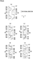
- Each of at least one slide gear 40 having a cam surface 71 is arranged to be moved in the axial direction by a shift fork 110, from a standby position where the slide gear is unconnected to a shift gear.
- the cam surface 71 of the slide gear 40 is formed to move that slide gear 40 in a direction away from the standby position in the axial direction, from the position to which the slide gear 40 has been moved by the shift fork 110.
- the slide gear 40 having the cam surface 71 is moved in a direction away from the standby position in the axial direction, from the position to which the slide gear 40 has been moved by the shift fork 110, by an elastic force of the cam biasing mechanism 80 exerted to the cam surface 71.
- FIG. 4(a) shows a state in which the slide gear 40 is at the standby position.
- FIG. 4(b) shows a state in which the slide gear 40 has been moved in the axial direction from the standby position, by the shift fork 110.
- FIG. 4(c) shows a state in which the slide gear 40 has been moved from the position shown in FIG. 4(b) by an elastic force of the cam biasing mechanism 80 exerted to the cam surface 71.
- the slide gear 40 when a torque transmitted to the transmission 1 is changed from a drive torque to a coast torque, the slide gear 40 may be required to be moved from a drive meshed position to a coast meshed position that is far from the standby position as compared to the drive meshed position. According to this arrangement, this requirement can be met by moving the slide gear 40 from the drive meshed position to the coast meshed position by the cam biasing mechanism 80, after the slide gear 40 is moved from the standby position to the drive meshed position by the shift fork 110.
- the transmission 1 of Third Embodiment is capable of performing seamless shift up, while avoiding the upsizing of the transmission 1.
- the state shown in FIG. 4(c) is a state in which the slide gear 40 is at the coast meshed position. It is noted that the state shown in FIG. 4(b) may be a state in which the slide gear 40 is at the drive meshed position. Alternatively, the state shown in FIG. 4(b) may be a state in which the slide gear 40 is at a position between the drive meshed position and the coast meshed position, when shift down is being performed.
- FIG. 5(a) shows an arrangement of slide gears 40 of the transmission 1 of Fourth Embodiment.
- FIG. 5(b) shows an arrangement of slide gears 40 of the transmission 1 of Fifth Embodiment.
- Each of the slide gears 40 shown in FIG. 5(a) and FIG. 5(b) is one of the slide gears 41 and 42 in the example shown in FIG. 1(a) and the slide gears 41, 42, and 43A in the example shown in FIG. 1(b) .
- the transmission 1 of each of Fourth Embodiment and Fifth Embodiment has features described below.
- each of at least one slide gear 40 having a cam surface 71 has a recess 46 with which a shift fork 110 is engaged.
- the cam surface 71 of the slide gear 40 is formed so that the maximum distance Da to the cam surface 71 from the axial center C11, C12 of the input shaft 11 or the output shaft 12 on which that slide gear 40 is provided is shorter than the minimum distance Db to the recess 46 from the axial center C11, C12 of the input shaft 11 or the output shaft 12 on which that slide gear 40 is provided.
- each of at least one slide gear 40 having a cam surface 71 has a protrusion 47 with which a shift fork 110 is engaged.
- the cam surface 71 of the slide gear 40 is formed so that the maximum distance Da to the cam surface 71 from the axial center C11, C12 of the input shaft 11 or the output shaft 12 on which that slide gear 40 is provided is shorter than the maximum distance Dc to the protrusion 47 from the axial center C11, C12 of the input shaft 11 or the output shaft 12 on which that slide gear 40 is provided.
- the transmission 1 can be downsized in the axial direction. Because in the transmission 1 of each of Fourth Embodiment and Fifth Embodiment the lengths of the input shaft 11 and the output shaft 12 are further arranged to be short, upsizing of the transmission 1 can be suppressed while seamless shift up is achieved.
- a slide gear 40 shown in FIG. 6 is one of the slide gears 41 and 42 in the example shown in FIG. 1(a) and the slide gears 41, 42, and 43A in the example shown in FIG. 1(b) .
- the transmission 1 of Sixth Embodiment has features described below.
- Each of at least one slide gear 40 having the cam surface 71 is formed such that the cam surface 71 of that slide gear 40 is radially inside a gear tooth surface 45 of that slide gear 40 on a plane that passes through at least part of the gear tooth surface 45 of that slide gear 40 and is orthogonal to the axial direction.
- a plane S1 shown in FIG. 6 is an example of the plane that passes through the gear tooth surface 45 of the slide gear 40 and is orthogonal to the axial direction. In this arrangement, when viewed in a direction orthogonal to the axial direction, at least part of the cam surface 71 overlaps at least part of the gear tooth surface 45.
- the input shaft 11 and the output shaft 12 can be arranged to be short. Because in the transmission 1 of Sixth Embodiment the lengths of the input shaft 11 and the output shaft 12 are further arranged to be short, upsizing of the transmission 1 can be suppressed while seamless shift up is achieved.
- the transmission 1 of Seventh Embodiment is a specific example of the transmission 1 of First Embodiment shown in FIG. 1(a) .
- the transmission 1 of Seventh Embodiment may have the arrangement of at least one transmission 1 of Second Embodiment to Sixth Embodiment.
- the transmission 1 is mounted on, for example, a vehicle (not illustrated) such as a motorcycle.
- vehicle includes a driving source 5 such as an engine, the transmission 1, a clutch 2, and a controller (not illustrated).
- the driving force generated by the driving source 5 is transmitted to a wheel that is a driving target 4 (see FIG. 1(a) ) through the clutch 2 and the transmission 1.
- the controller controls the driving source 5, the transmission 1, and the clutch 2.
- the transmission 1 is configured to be able to transmit power of the input shaft 11 to the output shaft 12.
- the ratio of the rotational speed of the input shaft 11 to the rotation speed of the output shaft 12 is termed a transmission ratio.
- the transmission 1 has plural speed stages (gear positions) that are different in transmission ratio.
- the speed stage of the transmission 1 is changed by the controller.
- the vehicle may include a shift operator (not illustrated) that is operated by the driver to change the speed stage of the transmission 1.
- the controller changes the speed stage of the transmission 1 in accordance with an operation of the shift operator.
- the controller may be arranged to be able to automatically change the speed stage of the transmission 1 in accordance with, for example, the vehicle speed, when the shift operator is not operated.
- the vehicle may not include a shift operator that is operated by the driver to change the speed stage of the transmission 1.
- the input shaft 11 is connected to the driving source 5 through the clutch 2.
- the driving source 5 is an engine
- the input shaft 11 is connected to the crankshaft of the engine.
- the clutch 2 is a friction clutch, for example, but is not limited to this.
- the clutch 2 is not a dual clutch.
- the transmission 1 is not a dual clutch transmission.
- the transmission 1 is an AMT (Automated Manual Transmission).
- the controller is arranged to be able to automatically change the power transmission ratio of the clutch 2 without requiring an operation by the driver.
- the controller may control at least one of the clutch 2 or the engine (driving source 5) when changing the speed stage of the transmission 1.
- the input shaft 11 is supported by bearings 11a and 11b.
- the output shaft 12 is supported by bearings 12a and 12b.
- At least one of the shift gears 31 to 36 may be supported by the input shaft 11 or the output shaft 12 through a bearing.
- At least one of the shift gears 31 to 36 may be supported by the input shaft 11 or the output shaft 12 without the intermediary of a bearing.
- the transmission 1 includes three slide gears 41, 42, and 43.
- the following will describe an arrangement in which the shift gears 31 to 36 are connected to the slide gears 41, 42, and 43.
- the slide gear 41 has dogs 51 that are provided at an end portion opposing the first speed gear 31 in the axial direction.
- the first speed gear 31 has dogs 61 that are connectable with the dogs 51 of the slide gear 41 by meshing therewith.
- the slide gear 41 has dogs 53 that are provided at an end portion opposing the third speed gear 33 in the axial direction.
- the third speed gear 33 has dogs 63 that are connectable with the dogs 53 of the slide gear 41 by meshing therewith.
- the slide gear 42 has dogs 52 that are provided at an end portion opposing the second speed gear 32 in the axial direction.
- the second speed gear 32 has dogs 62 that are connectable with the dogs 52 of the slide gear 42 by meshing therewith.
- the slide gear 42 has dogs 54 that are provided at an end portion opposing the fourth speed gear 34 in the axial direction.
- the fourth speed gear 34 has dogs 64 that are connectable with the dogs 54 of the slide gear 42 by meshing therewith.
- the slide gear 43 has dogs 55 that are provided at an end portion opposing the fifth speed gear 35 in the axial direction.
- the fifth speed gear 35 has dogs 65 that are connectable with the dogs 55 of the slide gear 43 by meshing therewith.
- the slide gear 43 has dogs 56 that are provided at an end portion opposing the sixth speed gear 36 in the axial direction.
- the sixth speed gear 36 has dogs 66 that are connectable with the dogs 56 of the slide gear 43 by meshing therewith.
- each of the slide gears 41, 42, and 43 is meshed with one of the shift gears 31 to 36 adjacent to the each slide gear in the axial direction, by means of the dogs.
- one of the shift gears 31 to 36 is meshed with a slide gear adjacent to the one shift gear in the axial direction by means of the dogs, power is transmitted from the input shaft 11 to the output shaft 12 through that shift gear and that slide gear.
- the first speed gear 31 is meshed with the slide gear 41
- the power from the input shaft 11 is transmitted to the gear 21, the first speed gear 31, the slide gear 41, and then the output shaft 12 in order.
- the speed stage of the transmission 1 in this case is the first speed stage.
- the speed stage of the transmission 1 in this case is the third speed stage.
- the speed stage of the transmission 1 in this case is the fifth speed stage.
- the transmission 1 is in a neutral state.
- the speed stage of the transmission 1 is controlled. In other words, the slide gears 41, 42, and 43 are driven in the axial direction in order to change the speed stage.
- the dogs 51 are aligned in the circumferential direction.
- the dogs 52 to 56 and 61 to 66 are also aligned in the circumferential direction.
- the dogs 51 to 56 of the slide gears 41, 42, and 43 are dog teeth. In other words, the dogs 51 to 56 are formed to protrude in the axial direction.
- the dogs 61 to 64 of the shift gears 31 to 34 are dog holes.
- the dogs 61 to 64 are concave in shape. In other words, the dogs 61 to 64 are dog holes that do not penetrate the shift gears 31 to 34 in the axial direction.
- the dogs 61 to 64 may be dog holes penetrating the shift gears 31 to 36 in the axial direction.
- the dogs 61 to 64 may be dog teeth. In this case, the dogs 51 to 54 may be dog teeth or dog holes.
- the dogs 65 and 66 of the shift gears 35 and 36 are dog teeth.
- the dogs 65 and 66 may be dog holes.
- FIG. 8(a) to FIG. 8(e) are developed sectional views of the second speed gear 32 and the slide gear 42.
- the up-down direction in each of FIG. 8(a) to FIG. 8(e) indicates the circumferential direction about the rotational central axis of the output shaft 12.
- the rotational direction of each of the shift gear 32 and the slide gear 42 is an upward direction in FIG. 8(a) to FIG. 8(e).
- FIG. 8(a) shows a state in which the transmission 1 is at a speed stage different from the second speed stage or at the neutral position.
- the arrows in FIG. 8(b) and FIG. 8(c) show the direction of the torque generated in the shift gear 32.
- the arrows in FIG. 8(d) and FIG. 8(e) show the rotational direction of the slide gear 42 relative to the shift gear 32 and the rotational direction of the shift gear 32 relative to the slide gear 42.
- the dog (dog tooth) 52 has a drive meshing surface 57, a coast meshing surface 58, and a release guide surface 59.
- the drive meshing surface 57 is close to the tip of the teeth as compared to the coast meshing surface 58.
- the drive meshing surface 57 is tilted in the circumferential direction relative to the axial direction.
- the drive meshing surface 57 is tilted so that one end of the surface close to the bottom of the teeth is on the downstream in the rotational direction of the shift gear 32 and the slide gear 42 as compared to the other end of the surface far from the bottom of the teeth.
- the drive meshing surface 57 may be formed to extend along the axial direction.
- the coast meshing surface 58 is tilted in the circumferential direction relative to the axial direction.
- the coast meshing surface 58 is tilted so that one end of the surface close to the tip of the teeth is on the downstream in the rotational direction of the shift gear 32 and the slide gear 42 as compared to the other end of the surface far from the tip of the teeth.
- the coast meshing surface 58 may be formed to extend along the axial direction.
- the release guide surface 59 is aligned with the drive meshing surface 57 in the circumferential direction.
- the release guide surface 59 is tilted in the axial direction relative to the circumferential direction.
- the release guide surface 59 may be spiral in shape relative to the rotational central axis of the output shaft 12, or may extend along the radial direction.
- the dog (dog hole) 62 has a drive meshing surface 67, a coast meshing surface 68, and a movement guiding surface 69.
- the tilt angle and the tilting direction of the drive meshing surface 67 relative to the axial direction are identical with those of the drive meshing surface 57 of the dog 52.
- the tilt angle and the tilting direction of the coast meshing surface 68 relative to the axial direction are identical with those of the coast meshing surface 58 of the dog 52.
- the movement guiding surface 69 is tilted in the axial direction relative to the circumferential direction.
- the movement guiding surface 69 may be spiral in shape relative to the rotational central axis of the output shaft 12, or may extend along the radial direction.
- FIG. 8(b) shows a state in which the drive meshing surface 57 is in contact with the drive meshing surface 67 and the dog 52 is meshed with the dog 62.
- This meshed state will be referred to as a drive meshed state.
- the position in the axial direction of the slide gear 42 when the slide gear 42 and the shift gear 32 are in the drive meshed state will be referred to as the drive meshed position of the slide gear 42 relative to the shift gear 32.
- the term "drive meshed position" is used no matter whether the drive meshed state is established.
- FIG. 8(c) shows a state in which the coast meshing surface 58 is in contact with the coast meshing surface 68 and the dog 52 is meshed with the dog 62.
- This meshed state will be referred to as a coast meshed state.
- the dogs 52 and 62 are deeply meshed with each other as compared to the drive meshed state.
- the position in the axial direction of the slide gear 42 when the slide gear 42 and the shift gear 32 are in the coast meshed state will be referred to as the coast meshed position of the slide gear 42 relative to the shift gear 32. It is noted that the term "coast meshed position" is used no matter whether the coast meshed state is established.
- the coast torque is a torque generated by the rotational inertia of the wheel and is exerted in the direction opposite to the drive torque.
- the coast torque is a torque transmitted between the engine and the wheel.
- the coast torque is generated when, for example, engine braking is performed.
- FIG. 8(d) shows a state in which an edge of the dog (dog tooth) 52 is in contact with the movement guiding surface 69.
- the slide gear 42 receives a force acting away from the shift gear 32.
- the transmission 1 is at the second speed stage and the torque transmitted to the transmission 1 is switched from the coast torque to the drive torque, the slide gear 42 rotates at a lower speed than the shift gear 32.
- FIG. 8(e) shows a state in which the edge of the dog (dog hole) 62 is in contact with the release guide surface 59.
- the edge of the dog 62 makes contact with the release guide surface 59 while the slide gear 42 rotates at a higher speed than the shift gear 32
- the slide gear 42 receives a force acting away from the shift gear 32.
- the release guide surface 59 is used when the speed stage is changed.
- the dogs (dog holes) 61 to 64 may be different from one another in shape, as long as they share the above-described common characteristics. At least two of or all of the dogs 61 to 64 may be symmetrical in shape.
- the dogs (dog teeth) 51 to 54 may be different from one another in shape. At least two of or all of the dogs 51 to 54 may be symmetrical in shape.
- the dogs (dog teeth) 51 to 54 are different from the dogs (dog teeth) 55 and 56 in shape.
- the dogs (dog teeth) 55 and 56 may be different in shape, identical in shape, or symmetrical in shape.
- the dogs (dog teeth) 65 and 66 may be different in shape, identical in shape, or symmetrical in shape.
- the dogs (dog teeth) 65 and 66 may be different from the dogs (dog teeth) 55 and 56 in shape, identical in shape, or symmetrical in shape.
- Each of the dogs 51 to 54 of the slide gears 41 and 42 has the release guide surface 59, whereas each of the dogs 61 to 64 of the shift gears 31 to 34 has the movement guiding surface 69.
- Each of the dogs of the slide gears 41 and 42 may have both the movement guiding surface and the release guide surface as in the dog of the slider of Patent Literature 1.
- the dog 54 of the slide gear 42 may not have the release guide surface 59.
- Each of the dogs 64 of the fourth speed gear 34 and the dogs 54 of the slide gear 42 may not have the movement guiding surface.
- the shape of each of the dogs 64 of the fourth speed gear 34 and the dogs 54 of the slide gear 42 may be identical with the shape of each of the dogs 65 and 66 of the shift gears 35 and 36 and the dogs 55 and 56 of the slide gear 43.
- the transmission 1 is arranged so that, when shifting up, the transmission 1 is temporarily in a double-meshed state where the two slide gears 41 and 42 are simultaneously meshed with two of the shift gears 31 to 34 through dogs.
- the two slide gears 41 and 42 are temporarily connected to two shift gears simultaneously.
- the transmission 1 is temporarily in the double-meshed state where the two slide gears 41 and 42 are simultaneously meshed with the shift gears 31 and 32 through the dogs 51, 52, 61, and 62.
- the slide gear 42 is meshed with the second speed gear 32 through the dogs 52 and 62, the slide gear 41 rotates at a higher speed than the first speed gear 31.
- the transmission 1 is arranged so that the movement of the slide gear 41 in the axial direction toward the first speed gear 31 is restricted in this case.
- the release guide surface 59 of the dog 51 of the slide gear 41 makes contact with the dog 61 of the first speed gear 31 and hence the slide gear 41 moves away from the first speed gear 31 in the axial direction. Due to this, the meshing between the dog 51 of the slide gear 41 and the dog 61 of the first speed gear 31 is canceled.
- the controller is not required to control the clutch 2 and the engine in order to reduce the pressing force generated in accordance with the power transmission between the dog 51 of the slide gear 41 and the dog 61 of the first speed gear 31.
- the transmission 1 is arranged so that a force of canceling the meshing of the dogs is generated in one of the two slide gears 41 and 42, when the double-meshed state is established.
- the transmission 1 is therefore able to seamlessly perform shift up to the second speed stage without blocking the power transmission.
- the transmission 1 is able to seamlessly perform shift up to the third speed stage and the fourth speed stage without blocking the power transmission.
- the transmission 1 is arranged so that the double-meshed state is not established when shifting down.
- the slide gears 41 and 42 may be different from one another in shape, as long as they share the below-described common characteristics.
- the slide gears 41 and 42 may be symmetrical in shape.
- the slide gear 42 is spline-fitted to the output shaft 12. As shown in FIG. 7 , in the inner circumferential surface of the slide gear 42, four cam surfaces 71 and two checking grooves 72 are formed. Each checking groove 72 is formed between two cam surfaces 71 that are aligned in the axial direction. The checking grooves 72 may not be formed.
- the slide gear 42 makes contact with a cam biasing mechanism 80 provided on the output shaft 12.
- the cam biasing mechanism 80 makes contact with the four cam surfaces 71 and the two checking grooves 72.
- the cam surface 71 of the slide gear 42 is separated from the dogs 52 and 54 of the slide gear 42 in the axial direction.
- the cam biasing mechanism 80 simultaneously makes contact with two cam surfaces 71 aligned in the circumferential direction among the four cam surfaces 71.
- the number of cam surfaces 71 formed to be aligned in the circumferential direction is not limited to two, and may be three or more.
- the number of checking grooves 72 formed to be aligned in the circumferential direction is not limited to two, and may be three or more.
- the checking grooves 72 may be a single groove that is continuous in the circumferential direction.
- the cam biasing mechanism 80 has a spring 81 which applies an elastic force to the slide gear 42 outward in the radial direction of the output shaft 12.
- the cam surface 71 is a slope surface tilted in the radial direction relative to the axial direction.
- the cam biasing mechanism 80 makes contact with the cam surface 71.
- the cam surface 71 is configured to convert an elastic force exerted in the radial direction from the cam biasing mechanism 80 to a force in the axial direction.
- the elastic force of the spring 81 acts as a force of pressing the slide gear 42 in the axial direction in which the checking groove 72 moves away from the cam biasing mechanism 80.
- the checking groove 72 is formed to allow the cam biasing mechanism 80 to be fitted thereto.
- the cam biasing mechanism 80 is fitted to the checking groove 72 of the slide gear 42.
- the slide gears 41, 42, and 43 are connected to the shift forks 111, 112, and 113, respectively.
- the shift forks 111, 112, and 113 are specific examples of the shift fork 110 of Third Embodiment.
- the slide gears 41, 42, and 43 move in the axial direction as the shift forks 111, 112, and 113 move in the axial direction.
- the shift forks 111, 112, and 113 are included in a shift mechanism in which the sliders 41, 42, and 43 are moved by the shift forks 111, 112, and 113.
- the shift mechanism includes an unillustrated shift actuator that is controlled by the controller. As the controller controls the shift actuator, the shift forks 111, 112, and 113 move in the axial direction.
- the structure of the shift mechanism is not particularly limited.
- the shift mechanism may be a mechanism including a shift drum, for example.
- parts of the shiftforks 111, 112, and 113 may be provided in grooves formed in the shift drum, respectively.
- parts of components connected to the shift forks 111, 112, and 113 so as to move in the axial direction together with the shift forks 111, 112, and 113 may be provided in grooves formed in the shift drum.
- a mechanism in which the shift drum is rotated by the shift actuator is not particularly limited.
- the shift mechanism may not include a shift drum.
- the transmission 1 may be a sequential manual transmission. In other words, the transmission 1 may be arranged so that, when the speed stage (gear position) is changed, the speed stage is changeable to only a speed stage that is adjacent to the speed stage before the change in terms of the transmission ratio.
- the transmission 1 of Eighth Embodiment is a specific example of the transmission 1 of First Embodiment shown in FIG. 1(b) .
- the transmission 1 of Eighth Embodiment may have the arrangement of at least one transmission 1 of Second Embodiment to Sixth Embodiment. The following will describe arrangements which are different from those of Seventh Embodiment.
- the transmission 1 includes four slide gears 41, 42, 43A, and 43B.
- the slide gears 43A and 43B are specific examples of the slide gears 43A and 43B shown in FIG. 1(b) . Between two slide gears 43A and 43B provided on the output shaft 12 and adjacent to each other in the axial direction, no bearing is provided.
- the slide gear 43A has dogs 155 that are provided at an end portion opposing the fifth speed gear 35 in the axial direction.
- the fifth speed gear 35 has dogs 165 that can be meshed with the dogs 155 of the slide gear 43A.
- the slide gear 43B has dogs 156 that are provided at an end portion opposing the sixth speed gear 36 in the axial direction.
- the sixth speed gear 36 has dogs 166 that can be meshed with the dogs 156 of the slide gear 43B.
- the dogs 155 are aligned in the circumferential direction.
- the dogs 156, 165, and 166 are also aligned in the circumferential direction.
- the dogs 155 and 156 of the slide gears 43A and 43B are dog teeth. In other words, the dogs 155 and 156 are formed to protrude in the axial direction.
- the dogs 165 and 166 of the shift gears 35 and 36 are dog holes.
- the dogs 165 and 166 are concave in shape. In other words, the dogs 165 and 166 are dog holes that do not penetrate the shift gears 35 and 36 in the axial direction.
- the dogs 165 and 166 may be dog holes penetrating the shift gears 35 and 36 in the axial direction.
- the dogs 165 and 166 may be dog teeth. In this case, the dogs 155 and 156 may be dog teeth or dog holes.
- the dogs (dog holes) 165 and 166 of the shift gears 35 and 36 have the same characteristics as the common characteristics of the dogs 61 to 64 of the shift gears 31 to 34 described in Eighth Embodiment.
- the dogs (dog teeth) 155 of the slide gears 43A and 43B have the same characteristics as the common characteristics of the dogs 51 to 54 of the slide gears 41 and 42 described in Eighth Embodiment.
- Each of the dogs 165 and 166 has a drive meshing surface 67, a coast meshing surface 68, and a movement guiding surface 69.
- Each of the dogs 155 and 156 has a drive meshing surface 57, a coast meshing surface 58, and a release guide surface 59.
- Each of the dogs 155 and 156 of the slide gears 43A and 43B may have both the movement guiding surface 69 and the release guide surface 59 as in the dog of the slider of Patent Literature 1.
- the dog 156 of the slide gear 43B may not have the release guide surface 59.
- Each of the dogs 166 of the sixth speed gear 36 and the dogs 156 of the slide gear 43 may not have the movement guiding surface.
- the shape of each of the dogs 166 of the sixth speed gear 36 and the dogs 156 of the slide gear 43B may be identical with the shape of each of the dogs 66 of the shift gear 36 and the dogs 56 of the slide gear 43 of Seventh Embodiment.
- the transmission 1 when shifting up to the fifth speed stage, the transmission 1 is temporarily in the double-meshed state where the two slide gears 42 and 43A are simultaneously meshed with the two shift gears 34 and 35 through the dogs. In this double-meshed state, a force of canceling the meshing through the dogs is generated in the slide gear 42.
- the transmission 1 When shifting up to the sixth speed stage, the transmission 1 is temporarily in the double-meshed state where the two slide gears 43A and 43B are simultaneously meshed with the two shift gears 35 and 36 through the dogs. In this double-meshed state, a force of canceling the meshing through the dogs is generated in the slide gear 43A.
- the transmission 1 is able to seamlessly perform shift up to the fifth speed stage and shift up to the sixth speed stage.
- the slide gear 43A is spline-fitted to the input shaft 11.
- one cam surface 71 and the checking groove 72 are formed to be aligned in the axial direction.
- the checking groove 72 may not be formed.
- the checking groove 72 is formed between the cam surface 71 and the dog 155.
- the slide gear 43A makes contact with a cam biasing mechanism 80 provided on the input shaft 11.
- the cam biasing mechanism 80 makes contact with the cam surface 71 and the checking groove 72.
- the cam biasing mechanism 80 has a spring 81 which applies an elastic force to the slide gear 43A outward in the radial direction of the input shaft 11.
- the cam surface 71 is a slope surface tilted in the radial direction relative to the axial direction.
- the cam biasing mechanism 80 makes contact with the cam surface 71.
- the elastic force of the spring 81 acts as a force of pressing the slide gear 43A in the axial direction in which the checking groove 72 moves away from the cam biasing mechanism 80.
- the checking groove 72 is formed to allow the cam biasing mechanism 80 to be fitted thereto.
- the cam biasing mechanism 80 is fitted to the checking groove 72 of the slide gear 43A.
- the slide gear 43B is spline-fitted to the input shaft 11.
- the slide gear 43B has neither the cam surface 71 nor the checking groove 72.
- the slide gears 43A and 43B are connected to the shift forks 113A and 113B, respectively.
- the shift forks 113A and 113B move in the axial direction in the same manner as the shift forks 111 and 112, as the controller controls an unillustrated shift actuator.
Landscapes
- Engineering & Computer Science (AREA)
- General Engineering & Computer Science (AREA)
- Mechanical Engineering (AREA)
- Structure Of Transmissions (AREA)
- Transmission Devices (AREA)
Abstract
Description
- The present teaching relates to a transmission, and particularly relates to a transmission capable of performing seamless shift up.
- In a known transmission having shift gears, a slider provided on a power transmission shaft (an input shaft or an output shaft) moves in the axial direction in order to change speed stages. As the slider moves in the axial direction, the slider is connected to a shift gear provided on the power transmission shaft or the slider is disconnected from a shift gear provided on the power transmission shaft. In the transmission, a driving force may be interrupted due to disconnection between the slider and the shift gear in shift up. As a scheme for shortening the time of interruption of the driving force, for example, seamless shift up has been demanded.
- For example,
Patent Literature 1 discloses a transmission which is capable of performing seamless shift up. The transmission ofPatent Literature 1 is arranged so that, when shifting up, two sliders are temporarily connected to the shift gear at the same time. In the transmission ofPatent Literature 1 in this state, a force in an axial direction is generated to cancel the connection of one of the two sliders. With this arrangement, seamless shift up is achieved without interrupting the transmission of power. In addition to this, the transmission ofPatent Literature 1 is provided with a cam biasing mechanism that is provided on the outer circumference of each of an input shaft and an output shaft so as to make contact with a cam surface on the slider. As the cam biasing mechanism is pressed onto the cam surface of the slider, the slider receives a force acting toward the shift gear. When a torque transmitted to the transmission is changed from a drive torque to a coast torque, the slider can be moved by the cam biasing mechanism from a meshed position where the drive torque is transmitted to a meshed position where the coast torque is transmitted. - [Patent Literature 1] International Publication No.
2020/250535 - In connection with the above, suppression of upsizing of the transmission has been demanded.
- An object of the present teaching is to suppress upsizing of a transmission that is capable of performing seamless shift up.
- The transmission comprises an input shaft connected to a driving source and an output shaft connected to a driving target, on the input shaft and the output shaft, shift gears being provided to be each rotatable relative to the input shaft or the output shaft and immovable in an axial direction of the input shaft and the output shaft, the shift gears corresponding to speed stages in number, on the input shaft and the output shaft, sliders being provided to be each rotatable together with the input shaft or the output shaft, movable in the axial direction, and connectable to at least one of the shift gears, two of the sliders being temporarily in a state of being connected simultaneously with two of the shift gears when shifting up, and in the state of being simultaneously connected, a force of canceling connection of one of the two sliders being generated, at least one cam biasing mechanism being provided on at least one of the input shaft or the output shaft and including a spring which exerts an elastic force in a radial direction of the input shaft or the output shaft, at least one of the sliders having a cam surface which makes contact with the cam biasing mechanism so as to covert the elastic force exerted in the radial direction from the cam biasing mechanism to a force exerted in the axial direction, the sliders being slide gears each of which has a gear tooth surface meshed with a shift gear that is provided on the input shaft or the output shaft, which is different from the shaft on which the each of the sliders is provided, at least one of the slide gears having the cam surface being moved on an outer circumferential surface of the input shaft or the output shaft on which the at least one of the slide gears is provided, by the at least one cam biasing mechanism that is formed on the input shaft or the output shaft on which the at least one of the slide gears is provided, and the cam surface of the at least one of the slide gears being arranged so that the maximum distance from the axial center of the input shaft or the output shaft on which the at least one of the slide gears is provided to the cam surface is shorter than the minimum distance from the axial center to the gear tooth surface of the at least one of the slide gears.
- According to this arrangement, at least one of the sliders has a cam surface. Alternatively, each of all sliders may have the cam surface. Each of the sliders is a slide gear having a gear tooth surface meshed with at least one shift gear. The slide gear functions as a slider and a gear meshed with a shift gear at a gear tooth surface. In this way, a gear meshed with a shift gear at a gear tooth surface and a slider are not independent from each other. On the other hand, the slider of
Patent Literature 1 is not a slide gear, and the slider is provided on each of an input shaft and an output shaft, in addition to a gear meshed with a shift gear at a gear tooth surface. On this account, in the transmission of the present invention, the input shaft and the output shaft can be arranged to be short as compared toPatent Literature 1. - At least one of the slide gears having the cam surface is moved on an outer circumferential surface of the input shaft or the output shaft on which the at least one of the slide gears is provided, by the at least one cam biasing mechanism that is formed on the input shaft or the output shaft on which the at least one of the slide gears is provided. The cam surface of the at least one of the slide gears is arranged so that the maximum distance from the axial center of the input shaft or the output shaft on which the at least one of the slide gears is provided to the cam surface is shorter than the minimum distance from the axial center of the gear tooth surface to the at least one of the slide gears. On this account, in the transmission of the present teaching, the distance between the input shaft and the output shaft is short as compared to
Patent Literature 1 in which a slider is provided to move a cam biasing mechanism provided on an outer circumference of each of an input shaft and an output shaft. - As described above, because in the transmission of the present teaching the lengths of the input shaft and the output shaft and the distance between the input shaft and the output shaft are arranged to be short, upsizing of the transmission can be suppressed while seamless shift up is achieved.
- (2) In addition to the arrangement (1) above, the transmission of the embodiment of the present teaching may be arranged as described below.
- At least part of a moving range of at least one of the slide gears provided on the input shaft overlaps at least part of a moving range of at least one of the slide gears provided on the output shaft, when viewed in a direction orthogonal to the axial direction.
- According to this arrangement, at least part of a moving range of at least one of the slide gears provided on the input shaft overlaps at least part of a moving range of at least one of the slide gears provided on the output shaft, when viewed in a direction orthogonal to the axial direction. On this account, as compared to a case where the moving range on the input shaft does not overlap the moving range on the output shaft, the input shaft and the output shaft can be arranged to be short. In particular, according to
Patent Literature 1, at least part of a moving range of at least one slider provided on the input shaft does not overlap at least part of a moving range of at least one slider provided on the output shaft, when viewed in a direction orthogonal to the axial direction of the input shaft and the output shaft. On this account, in the transmission of the present teaching, the input shaft and the output shaft can be arranged to be short as compared toPatent Literature 1. - As described above, because in the transmission of the present teaching the lengths of the input shaft and the output shaft are further shortened, upsizing of the transmission can be suppressed while seamless shift up is achieved.
- (3) In addition to the arrangement (1) or (2) above, the transmission of the embodiment of the present teaching may be arranged as described below.
- Each of the at least one of the slide gears having the cam surface is arranged to be moved in the axial direction by a shift fork, from a standby position where the each slide gear is unconnected to a shift gear, and
the cam surface of the each slide gear is formed to move the each slide gear in a direction away from the standby position in the axial direction, from the position to which the each slide gear has been moved by the shift fork. - With this arrangement, without using the shift fork, the slide gear can be moved away from the standby position from a position to which the slide gear has been moved by the shift fork, by an elastic force of the cam biasing mechanism. In a transmission capable of performing seamless shift up, as in
Patent Literature 1, when a torque transmitted to the transmission is changed from a drive torque to a coast torque, the slider may be required to be moved from a drive meshed position to a coast meshed position. The drive meshed position is a position where the drive torque is transmitted. The coast meshed position is a position where the coast torque is transmitted. According to the arrangement above, the requirement can be met by moving the slide gear from the drive meshed position to the coast meshed position by the cam biasing mechanism, after the slide gear is moved from the standby position to the drive meshed position by the shift fork. On this account, the transmission of the present teaching is capable of performing seamless shift up, while avoiding the upsizing of the transmission. - (4) In addition to any one of the arrangements (1) to (3) above, the transmission of the embodiment of the present teaching may be arranged as described below.
- Each of the at least one of the slide gears having the cam surface has a recess or a protrusion to which the shift fork is fitted, and the cam surface of the at least one of the slide gears is formed so that the maximum distance from the axial center to cam surface is shorter than either the minimum distance from the axial center to the recess or the maximum distance from the axial center to the protrusion.
- According to this arrangement, the shift fork is fitted to the recess or the protrusion of at least one slide gear having the cam surface. The cam surface of the slide gear is formed so that the maximum distance from the axial center to the cam surface is shorter than either the minimum distance from the axial center to the recess or the maximum distance from the axial center to the protrusion. On this account, the transmission can be downsized in the axial direction. Due to the above, because in the transmission of the present teaching the lengths of the input shaft and the output shaft are further shortened, upsizing of the transmission can be suppressed while seamless shift up is achieved.
- (5) In addition to any one of the arrangements (1) to (4) above, the transmission of the embodiment of the present teaching may be arranged as described below.
- Each of the at least one of the slide gears having the cam surface is formed so that the cam surface of the each slide gear is positioned inside in the radial direction of the gear tooth surface of the each slide gear, on a plane which at least partially passes through the gear tooth surface of the each slide gear and is orthogonal to the axial direction.
- According to this arrangement, the cam surface is provided radially inside the gear tooth surface on a plane that is orthogonal to the axial direction of the input shaft or the output shaft on which at least one slide gear having the cam surface is provided and passes through at least part of the gear tooth surface. To put it differently, when viewed in a direction orthogonal to the axial direction, at least part of the cam surface overlaps at least part of the gear tooth surface. On this account, as compared to a case where the cam surface does not overlap the gear tooth surface, the input shaft and the output shaft can be arranged to be short. Due to the above, because in the transmission of the present teaching the lengths of the input shaft and the output shaft are further shortened, upsizing of the transmission can be suppressed while seamless shift up is achieved.
- (6) In addition to any one of the arrangements (1) to (5) above, the transmission of the embodiment of the present teaching may be arranged as described below.
- The at least one of the slide gears having the cam surface is a switching slide gear connectable to two of the shift gears provided on the same shaft as the at least one of the slide gears, and speed stages corresponding to the two of the shift gears connected to the switching slide gear are different from each other by at least two speed stages.
- According to this arrangement, the switching slide gear provided on the input shaft or the output shaft can be connected to two shift gears. Furthermore, the two shift gears connected to the switching slide gear correspond to speed stages that are different from each other by at least two speed stages. On this account, the transmission can be arranged to achieve seamless shift up by utilizing the movement of the switching slide gear having the cam surface. As compared to a transmission which is arranged so that no switching slide gear is provided and a slide gear having a cam surface is connectable to only one shift gear, it is possible to shorten the input shaft and the output shaft. On this account, the transmission of the present teaching is capable of performing seamless shift up, while improving the degree of freedom in designing the transmission and avoiding the upsizing of the transmission.
- (7) In addition to any one of the arrangements (1) to (6) above, the transmission of the embodiment of the present teaching may be arranged as described below.
- The slide gears include; two end portion slide gears which are provided at respective ends in the axial direction and are provided on the same one of the input shaft and the output shaft; and at least one slide gear which is provided on the input shaft or the output shaft, which is different from the shaft on which the two end portion slide gears are provided, and at least one of the two end portion slide gears has the cam surface.
- According to this arrangement, when two slide gears at the ends in the axial direction of the slide gears are two end portion slide gears, the two end portion slide gears are provided on the same shaft (the input shaft or the output shaft). Among the slide gears, each slide gear different from the two end portion slide gears is provided on a shaft different from the shaft on which the two end portion slide gears are provided. At least one of the two end portion slide gears has the cam surface. On this account, it is possible to realize a design with which seamless shift up is achieved by using the end portion slide gear having the cam surface. In this way, the transmission of the present teaching is capable of performing seamless shift up, while improving the degree of freedom in designing the transmission and avoiding the upsizing of the transmission.
- (8) In addition to any one of the arrangements (1) to (7) above, the transmission of the embodiment of the present teaching may be arranged as described below.
- Two of the shift gears, which are provided at respective ends in the axial direction, are a first speed gear and a second speed gear.
- As compared to the third and higher speed gears, a reaction force exerted to the shift gear is large in the first speed gear and the second speed gear. On this account, when the two shift gears at the both ends in the axial direction of the shift gears are not the first speed gear and the second speed gear, the diameter of at least one of the input shaft or the output shaft or the distance between the input shaft and the output shaft must be long in order to suppress the deflection of at least one of the input shaft or the output shaft, as compared to a case where the two shift gears at the both ends in the axial direction of the shift gears are the first speed gear and the second speed gear. According to the arrangement above, the diameter of at least one of the input shaft or the output shaft and the distance between the input shaft and the output shaft can be reduced as compared to a case where the two shift gears at the both ends in the axial direction of the shift gears are not the first speed gear and the second speed gear. Due to this, in the transmission of the present teaching, while seamless shift up can be achieved, upsizing of the transmission can be suppressed by further shortening the diameter of at least one of the input shaft or the output shaft and the distance between the input shaft and the output shaft.
- (9) In addition to the arrangement (8) above, the transmission of the embodiment of the present teaching may be arranged as described below.
- The number of the shift gears is six, and the shift gears include a third speed gear, a fourth speed gear, a fifth speed gear, and a sixth speed gear in addition to the first speed gear and the second speed gear, the slide gears include a fifth-speed slide gear connectable to the fifth speed gear and a sixth-speed slide gear connectable to the sixth speed gear, and the fifth-speed slide gear and the sixth-speed slide gear are movable in the axial direction relative to each other, and the fifth speed gear, the fifth-speed slide gear, the sixth-speed slide gear, and the sixth speed gear are provided in this order on the same shaft, and the fifth-speed slide gear has the cam surface.
- According to this arrangement, the fifth-speed slide gear and the sixth-speed slide gear connected to the fifth speed gear and the sixth speed gear provided on the same shaft are independently provided. On this account, the transmission can be arranged to achieve seamless shift up from the fifth speed stage to the sixth speed stage by utilizing the movement of the fifth-speed slide gear having the cam surface and the sixth-speed slide gear. Consequently, the transmission of the present teaching is capable of performing seamless shift up, while improving the degree of freedom in designing the transmission and avoiding the upsizing of the transmission.
- (10) In addition to any one of the arrangements (1) to (9) above, the transmission of the embodiment of the present teaching may be arranged as described below.
- Except bearings used for providing the shift gears, there is no bearing between two of the slide gears, which are provided on the same one of the input shaft and the output shaft and adjacent to each other in the axial direction.
- According to this arrangement, there is no bearing between two slide gears which are provided on the same one of the input shaft and the output shaft and adjacent to each other in the axial direction. This bearing excludes the bearings used for providing the shift gears. On this account, in the transmission of the present teaching, the input shaft and the output shaft are short as compared to a case where a bearing is provided between two sliders that are on the same shaft and are adjacent to each other in the axial direction. Consequently, the transmission of the present teaching is capable of performing seamless shift up, while avoiding the upsizing of the transmission by further shortening the input shaft and the output shaft.
- In the present teaching and the embodiments, a transmission is provided on at least part of a power transmission path. The power transmission path is a path through which power is transmitted from a driving source to a driving target. The transmission is configured to change a transmission ratio. The transmission ratio is a ratio of rotation speed of an input shaft of the transmission to rotation speed of an output shaft of the transmission. The transmission may include a transmission device configured to change a transmission ratio and a speed reducer configured to reduce the rotation speed of power output from the transmission device, by means of gears, etc. The reduction ratio of the speed reducer is unchanged. In the present teaching and the description, the transmission is a multistage transmission which has plural shift gears that are immovable in the axial direction of each of the input shaft and the output shaft and correspond to speed stages in number, and which is configured to transmit power from the input shaft to the output shaft through a shift gear correspond to a selected speed stage. The transmission of the present teaching and the description does not include a continuously variable transmission device having no shift gear. The transmission of the present teaching and the embodiments may include an auxiliary transmission.
- In the present teaching and the embodiments, the transmission is a multistage transmission. In the present teaching and the embodiments, the transmission is a non-synchronous transmission. In the present teaching and the embodiments, the transmission is a constant-mesh transmission. In the present teaching and the embodiments, the transmission may be an AMT (Automated Manual transmission) or an MT (Manual Transmission). The AMT is also known as a semi-automatic transmission.
- In the present teaching and the embodiments, the transmission is mounted on a vehicle, for example. The vehicle on which the transmission is mounted may be a straddled vehicle or an automobile. The straddled vehicle includes a motorcycle, a motor tricycle, a four-wheeled buggy (ATV: All Terrain Vehicle), a snowmobile, and a personal watercraft, for example. The motorcycle includes a scooter, an engine-equipped bicycle, a moped, etc. In the present teaching and the embodiments, for example, the transmission may be mounted on an apparatus such as an agricultural machine, which is not a vehicle.
- In the present teaching and the embodiments, the driving source is a power source for driving a driving target. The driving target is a vehicle, for example, and is at least one driving wheel among at least one front wheel or at least one rear wheel, when the transmission is mounted on a vehicle. The driving source may include an engine. The driving source may include an engine and an electric motor. The driving source may include an engine and an electric motor with a power generation function of generating power by the output of the engine (or a generator and an electric motor). In this case, the output of the engine may be used solely for the power generation.
- In the present teaching and the embodiments, the axial direction of each of the input shaft and the output shaft is a direction in parallel to each of the rotational central axis of the input shaft and the rotational central axis of the output shaft.
- In the present teaching and the description, a moving range indicates a part in the axial direction of the outer circumferential surface of each of the input shaft and the output shaft, where plural slide gears move. The moving range is a part in the axial direction of the outer circumferential surface of each of the input shaft and the output shaft, where plural slide gears move, and is either a splined part where grooves extending along the axial direction are formed in the outer circumferential surface of each of the input shaft and the output shaft or a cylindrical part.
- In the present teaching and the description, a cam biasing mechanism is formed on either an input shaft or an output shaft on which a slide gear having a cam surface is provided. The cam biasing mechanism may be any mechanism as long as it applies an elastic force to the cam surface of the slide gear in the radial direction of the shaft. The cam biasing mechanism may be formed entirely or partially by a spring. The spring may be a coil spring or a disc spring. In the present teaching and the description, the cam surface is provided on at least one slide gear and moves on the outer circumferential surface of the input shaft or the output shaft on which the slide gear is provided.
- In the present teaching and the embodiments, at least one of plural options encompasses all conceivable combinations of the options. At least one of plural options may be one of the options, some of the options, or all of the options. For example, at least one of A, B, or C indicates only A, only B, only C, A and B, A and C, B and C, or A, B, and C.
- In the claims, when the number of a constituent feature is not clearly specified and the constituent feature is expressed in a singular form in English, the number of the constituent feature may be more than one in the present teaching. In the present teaching, the number of the constituent features may be only one.
- In the present teaching and the embodiments, terms "including", "comprising", "having", and derivatives thereof are used to encompass not only listed items and equivalents thereof but also additional items.
- In the present teaching and the embodiments, the terms "mounted", "connected", "coupled", and "supported" are used in broad sense. Specifically, not only direct attachment, connection, coupling, and support but also indirect attachment, connection, coupling, and support are included. Further, connected and coupled are not limited to physical or mechanical connections and couplings. They also include direct or indirect electrical connections and couplings.
- Unless otherwise defined, all terms (technical and scientific terms) used in this specification and claims indicate meanings typically understood by a person with ordinary skill in the art in the technical field to which the present teaching belongs. Terms such as those defined in commonly used dictionaries are to be interpreted as having meaning that is consistent with their meaning in the context of the relevant art and the present disclosure, and are not to be interpreted in an idealized or excessively formal sense.
- In the present teaching and the embodiments, the term "preferable" is non-exclusive. The term "preferable" means "preferable but not limited to". In this specification, an arrangement which is "preferable" exerts at least the above-described effects of the arrangement of
claim 1. In this specification, the term "may" is non-exclusive. The term "may" indicate "may but not must". In this specification, an arrangement which is explained by using the term "may" exerts at least the above-described effects of the arrangement ofclaim 1. - In the present teaching and the embodiments, the preferred arrangements of the different aspects described above may be variously combined. Before the embodiments of the present teaching are detailed, it is informed that the present teaching is not limited to the configurations and layout of elements described below and/or shown in drawings. The present teaching is also applicable to embodiments other than the embodiments described later. The present teaching may be implemented as an embodiment other than the below-described embodiment. Furthermore, the present teaching may be implemented by suitably combining below-described embodiments and modifications.
- The transmission of the present teaching is capable of performing seamless shift up, while upsizing of the transmission is avoided.
-
-
FIG. 1 includes schematic diagrams illustrating a structure of a transmission of First Embodiment. -
FIG. 2 is a schematic diagram illustrating another structure of the transmission of First Embodiment. -
FIG. 3 includes schematic diagrams illustrating a structure of a transmission of Second Embodiment. -
FIG. 4 includes schematic diagrams illustrating movement of a slide gear in Third Embodiment. -
FIG. 5 includes schematic diagrams illustrating structures of slide gears of Fourth Embodiment and Fifth Embodiment. -
FIG. 6 is a schematic cross section of the slide gear of Sixth Embodiment. -
FIG. 7 is a schematic cross section of a transmission of Seventh Embodiment. -
FIG. 8 includes developed sectional views of a shift gear and a slide gear of the transmission of Seventh Embodiment. -
FIG. 9 is a schematic cross section of a transmission of Eighth Embodiment. - The following will describe a
transmission 1 of First Embodiment of the present teaching with reference toFIG. 1(a) and FIG. 1(b). FIG. 1(a) and FIG. 1(b) show two examples of thetransmission 1 of First Embodiment. Thetransmission 1 of First Embodiment may be structurally different from those inFIG. 1(a) and FIG. 1(b) . - The
transmission 1 includes aninput shaft 11 and anoutput shaft 12. Thetransmission 1 is configured to be able to transmit power of theinput shaft 11 to theoutput shaft 12. Theinput shaft 11 is connected to a drivingsource 5. Theoutput shaft 12 is connected to a drivingtarget 4. On theinput shaft 11 and theoutput shaft 12, shift gears 31, 32, 33, 34, 35, and 36 are provided to correspond to speed stages in number. In other words, on theinput shaft 11 or theoutput shaft 12, shift gears 31, 32, 33, 34, 35, and 36 are provided to correspond to speed stages in number. In the examples shown inFIG. 1(a) and FIG. 1(b) , the maximum number of speed stage is six. Each of the shift gears 31, 32, 33, 34, 35, and 36 is provided to be rotatable relative to theinput shaft 11 or theoutput shaft 12 and immovable in the axial direction of theinput shaft 11 or theoutput shaft 12. The shift gears 31, 32, 33, 34, 35, and 36 are a first speed gear, a second speed gear, a third speed gear, a fourth speed gear, a fifth speed gear, and a sixth speed gear, respectively. InFIG. 1 , an arrow X indicates the axial direction of each of theinput shaft 11 and theoutput shaft 12. In the descriptions below, an axial direction indicates the axial direction of each of theinput shaft 11 and theoutput shaft 12. - On the
input shaft 11 and theoutput shaft 12,sliders sliders input shaft 11 or theoutput shaft 12 and movable in the axial direction. Each of thesliders sliders input shaft 11 to theoutput shaft 12. In the examples shown inFIG. 1(a) and FIG. 1(b) , theslider 41 having been moved is connected to theshift gear 31 or theshift gear 33. Theslider 42 having been moved is connected to theshift gear 32 or theshift gear 34. Theslider 43 having been moved is connected to theshift gear 35 or theshift gear 36. In the example shown inFIG. 1(a) , the number ofsliders 43 is one. In the example shown inFIG. 1(b) , the number ofsliders 43 is two, which aresliders - Two of the
sliders transmission 1 is able to perform seamless shift up without interrupting the power. In the example shown inFIG. 1(a) , thetransmission 1 is arranged to be able to seamlessly perform shift up to the second speed, the third speed, and the fourth speed. In the example shown inFIG. 1(b) , thetransmission 1 is arranged to be able to seamlessly perform shift up to the second speed stage, the third speed stage, the fourth speed stage, the fifth speed stage, and the sixth speed stage. - The
transmission 1 includes at least onecam biasing mechanism 80. The at least onecam biasing mechanism 80 is provided on at least one of theinput shaft 11 or theoutput shaft 12. Eachcam biasing mechanism 80 includes aspring 81. Thespring 81 exerts an elastic force in the radial direction of theinput shaft 11 or theoutput shaft 12. - At least one of the
sliders cam surface 71. The at least one slider having thecam surface 71 among thesliders slider 40. In the examples shown inFIG. 1(a) and FIG. 1(b) , each of the twosliders cam surface 71. In the example shown inFIG. 1(b) , theslider 43A among the twosliders 43 has thecam surface 71, too. The number ofsliders 40 having thecam surface 71 may be one or more than one. Thecam surface 71 is formed on one of the two sliders simultaneously connected to two shift gears when shifting up, to which a force of canceling the connection is applied. Thecam surface 71 makes contact with thecam biasing mechanism 80 so as to convert an elastic force exerted in the radial direction from thecam biasing mechanism 80 to a force exerted in the axial direction. Thecam biasing mechanism 80 is provided for eachslider 40 having thecam surface 71. - The
sliders gear tooth surface 45 which is meshed with a shift gear that is provided on theinput shaft 11 or theoutput shaft 12, which is different from the shaft on which that slide gear is provided. Onegear tooth surface 45 is meshed with one shift gear. Each of the slide gears 41, 42, and 43 has at least onegear tooth surface 45 meshed with at least one shift gear. Eachgear tooth surface 45 is always meshed with one of the shift gears 31 to 36. In the examples shown inFIG. 1(a) and FIG. 1(b) , theslide gear 41 has onegear tooth surface 45 meshed with theshift gear 35, and theslide gear 42 has onegear tooth surface 45 meshed with theshift gear 36. In the example shown inFIG. 1(a) , theslide gear 43 has two gear tooth surfaces 45 meshed with two shift gears 33 and 34, respectively. In the example shown inFIG. 1(b) , theslide gear 43A has onegear tooth surface 45 meshed with theshift gear 33, and theslide gear 43B has onegear tooth surface 45 meshed with theshift gear 34. - In the examples shown in
FIG. 1(a) and FIG. 1(b) , on theinput shaft 11, ameshing gear 21, afifth speed gear 35, aslide gear 43, asixth speed gear 36, and ameshing gear 22 are provided in this order in the axial direction. Among these members, themeshing gear 21 is closest to an end portion of theinput shaft 11, with which the drivingsource 5 is connected. On theinput shaft 12, afirst speed gear 31, aslide gear 41, athird speed gear 33, afourth speed gear 34, aslide gear 42, and asecond speed gear 32 are provided in this order in the axial direction. Among these members, thefirst speed gear 31 is closest to an end portion of theinput shaft 11, with which the drivingsource 5 is connected. Each of themeshing gear 21 and themeshing gear 22 is arranged to be rotatable together with theinput shaft 11 and immovable in the axial direction. - At least one
cam biasing mechanism 80 is formed on theinput shaft 11 or theoutput shaft 12, on which at least oneslide gear 40 having thecam surface 71 is provided. In other words, at least onecam biasing mechanism 80 is formed on at least one of theinput shaft 11 or theoutput shaft 12, on which at least oneslide gear 40 having thecam surface 71 is provided. Thecam biasing mechanism 80 is provided for eachslide gear 40 having thecam surface 71. In the example shown inFIG. 1(a) , twocam biasing mechanisms 80 are formed on theoutput shaft 12 on which slide gears 41 and 42 are provided. In the example shown inFIG. 1(b) , threecam biasing mechanisms 80 are formed on theinput shaft 11 and theoutput shaft 12 on which slide gears 41, 42, and 43A are provided. At least oneslide gear 40 having thecam surface 71 is arranged to be moved on the outer circumferential surface of theinput shaft 11 or theoutput shaft 12 on which the at least oneslide gear 40 is provided, by at least onecam biasing mechanism 80. Thecam surface 71 of theslide gear 40 is arranged so that the maximum distance from the axial center (C11 or C12) of theinput shaft 11 or theoutput shaft 12 on which the at least oneslide gear 40 is provided to thecam surface 71 is shorter than the minimum distance from the axial center (C11 or C12) of the gear tooth surfaces 45 to the slide gears 41 and 42. The axial center C11 is the axial center of theinput shaft 11, whereas the axial center C12 is the axial center of theoutput shaft 12. In the case of thecam surface 71 of theslide gear 41 shown inFIG. 1(a) , thecam surface 71 of theslide gear 41 is arranged so that the maximum distance from the axial center C12 of theoutput shaft 12 on which theslide gear 41 is provided to thecam surface 71 is shorter than the minimum distance from the axial center C12 of thegear tooth surface 45 to theslide gear 41. - Because in the
transmission 1 of First Embodiment the lengths of theinput shaft 11 and theoutput shaft 12 and the distance between theinput shaft 11 and theoutput shaft 12 are arranged to be short, upsizing of thetransmission 1 can be suppressed while seamless shift up is achieved. - While the highest speed stage of the
transmission 1 of First Embodiment shown inFIG. 1(a) and FIG. 1(b) is the sixth speed stage, the highest speed stage of thetransmission 1 of First Embodiment may not be the sixth speed stage but be any speed stage. The arrangement of the shift gears of thetransmission 1 of First Embodiment may be different from the arrangement in the examples ofFIG. 1(a) and FIG. 1(b) . In the examples of thetransmission 1 shown inFIG. 1(a) and FIG. 1(b) , on theinput shaft 11 and theoutput shaft 12, thefirst speed gear 31, thefifth speed gear 35, thethird speed gear 33, thefourth speed gear 34, thesixth speed gear 36, and thesecond speed gear 32 are provided in this order in the axial direction. For example, as in the example of thetransmission 1 shown inFIG. 2 , on theinput shaft 11 and theoutput shaft 12, thesecond speed gear 32, thesixth speed gear 36, thefourth speed gear 34, thethird speed gear 33, thefirst speed gear 31, and thefifth speed gear 35 may be provided in order in the axial direction. In the example ofFIG. 2 , on theinput shaft 11, themeshing gear 22, thesixth speed gear 36, theslide gear 43, thefirst speed gear 31, and themeshing gear 25 are provided in this order in the axial direction. To put it differently, on theinput shaft 11 and theoutput shaft 12, the even-number-th shift gears and the odd-number-th shift gears are provided in this order in the axial direction, or the odd-number-th shift gears and the even-number-th shift gears are provided in this order in the axial direction. - In the examples shown in
FIG. 1(a) and FIG. 1(b) , the two end portion slide gears 41 and 42 at the respective ends in the axial direction among the slide gears 41, 42, and 43 are on the same one of theinput shaft 11 andoutput shaft 12. Thesliders slide gear 43 which is provided on a shaft different from theinput shaft 11 or theoutput shaft 12 on which the two end portion slide gears 41 and 42 are provided. In the examples shown inFIG. 1(a) and FIG. 1(b) , each of the two end portion slide gears 41 and 42 has thecam surface 71. Alternatively, only one of the two end portion slide gears 41 and 42 may have thecam surface 71. - In the examples shown in
FIG. 1(a) and FIG. 1(b) , two shift gears at the both ends in the axial direction among the shift gears 31 to 36 are thefirst speed gear 31 and thesecond speed gear 32. While in the examples shown inFIG. 1(a) and FIG. 1(b) thefirst speed gear 31 and thesecond speed gear 32 are both provided on theoutput shaft 12, the disclosure is not limited to this arrangement. In thetransmission 1 of First Embodiment, thefirst speed gear 31 and thesecond speed gear 32 may be provided at the both ends in the axial direction among the shift gears 31 to 36 and provided both on theinput shaft 11. Because the two shift gears at the both ends in the axial direction of the shift gears 31 to 35 are thefirst speed gear 31 and thesecond speed gear 32, the diameter of at least one of theinput shaft 11 or theoutput shaft 12 and the distance between theinput shaft 11 and theoutput shaft 12 can be reduced as compared to a case where the two shift gears at the both ends in the axial direction of the shift gears 31 to 35 are not thefirst speed gear 31 and thesecond speed gear 32. On this account, thetransmission 1 is capable of performing seamless shift up, while avoiding the upsizing of thetransmission 1. - In the
transmission 1 of First Embodiment, the two shift gears at the both ends in the axial direction among the shift gears 31 to 36 may not be thefirst speed gear 31 and the second speed gear 32 (see e.g.,FIG. 2 ). - In the example shown in
FIG. 1(b) , the slide gears 41, 42, and 43 include a fifth-speed slide gear 43 (43A) connectable with thefifth speed gear 35 and a sixth-speed slide gear 43 (43B) connectable with thesixth speed gear 36. The fifth-speed slide gear 43 (43A) and the sixth-speed slide gear 43 (43B) are movable relative to each other in the axial direction. Thefifth speed gear 35, the fifth-speed slide gear 43 (43A), the sixth-speed slide gear 43 (43B), and thesixth speed gear 36 are provided in this order on the same shaft in the axial direction. The fifth-speed slide gear 43 (43A) is provided with acam surface 71. In the example shown inFIG. 1(b) , thefifth speed gear 35, the fifth-speed slide gear 43, the sixth-speed slide gear 43, and thesixth speed gear 36 are provided on theinput shaft 11. Alternatively, these members may be provided on theoutput shaft 12. As the slide gears connected to thefifth speed gear 35 and thesixth speed gear 36, respectively, are different, it is possible to arrange thetransmission 1 so that seamless shift up from the fifth speed stage to the sixth speed stage is achieved by sliding of the fifth-speed slide gear 43 (43A) having thecam surface 71 and the sixth-speed slide gear 43 (43B). On this account, thetransmission 1 shownFIG. 1(b) is capable of performing seamless shift up, while improving the degree of freedom in designing thetransmission 1 and avoiding the upsizing of thetransmission 1. - In the examples shown in
FIG. 1(a) and FIG. 1(b) , theslide gear cam surface 71 is a switching slide gear. In the example shown inFIG. 1(b) , theslide gear 43 having thecam surface 71 is not a switching slide gear. A switching slide gear can be connected with two shift gears among the shift gears 31 to 36, which are provided on the same shaft (either theinput shaft 11 or the output shaft 12) as the switching slide gear. Furthermore, the two shift gears connected to the switching slide gear correspond to speed stages that are different from each other by at least two speed stages. In the examples shown inFIG. 1(a) and FIG. 1(b) , the switchingslide gear 41 provided on theoutput shaft 12 can be connected to two shift gears 31 and 33. Furthermore, the switchingslide gear 42 provided on theoutput shaft 12 can be connected to two shift gears 32 and 34. The speed stages to which the two shift gears connected to the switching slide gear correspond may not be limited to the above, on condition that the speed stages are different from each other by at least two speed stages. Because aslide gear 40 having thecam surface 71 is a switching slide gear, thetransmission 1 can be arranged to achieve seamless shift up by utilizing the movement of the switchingslide gear 40 having thecam surface 71. As compared to a transmission which is arranged so that no switching slide gear is provided and a slide gear having a cam surface is connectable to only one shift gear, it is possible to shorten theinput shaft 11 and theoutput shaft 12. On this account, thetransmission 1 shownFIG. 1(a) and FIG. 1(b) is capable of performing seamless shift up, while improving the degree of freedom in designing thetransmission 1 and avoiding the upsizing of thetransmission 1. - The
transmission 1 of First Embodiment may not include the switching slide gear. In other words, the slide gear having the cam surface may be arranged to be connectable to only one shift gear. Furthermore, all slide gears may be switching slide gears as shown in the example ofFIG. 1(a) , or some slide gears may be switching slide gears as shown in the example ofFIG. 1(b) . - The following will describe a
transmission 1 of Second Embodiment of the present teaching with reference toFIG. 3(a) and FIG. 3(b) . In addition to the characteristics of thetransmission 1 of First Embodiment, thetransmission 1 of Second Embodiment has features described below. - The
input shaft 11 has movingranges slide gear output shaft 12 has a movingrange 143 within which at least oneslide gear 43 moves in the axial direction. InFIG. 3(a) and FIG. 3(b) , the moving ranges 141, 142, and 143 are hatched by oblique lines. Slide gears 41, 42, and 43 of Second Embodiment are provided so that at least part of the movingranges slide gear input shaft 11 overlap at least part of the movingrange 143 of at least oneslide gear 43 provided on theoutput shaft 12, when viewed in a direction orthogonal to the axial direction. InFIG. 3(a) and FIG. 3(b) , an arrow Y indicates the direction orthogonal to the axial direction of theinput shaft 11 and theoutput shaft 12. In the example shown inFIG. 3(a) , part of the movingrange 143 of theinput shaft 11 overlaps part of the movingrange 141 and part of the movingrange 142 of theoutput shaft 12 when viewed in the direction orthogonal to the axial direction. In the example shown inFIG. 3(b) , part of the movingrange 143 of theslide gear 43A (43) of theinput shaft 11 overlaps part of the movingrange 141 of theoutput shaft 12 when viewed in the direction orthogonal to the axial direction, and part of the movingrange 143 of theslide gear 43B (43) of theinput shaft 11 overlaps part of the movingrange 142 of theoutput shaft 12 when viewed in the direction orthogonal to the axial direction. As compared toPatent Literature 1, theinput shaft 11 and theoutput shaft 12 can be arranged to be short in thetransmission 1 of Second Embodiment. - The following will describe a
transmission 1 of Third Embodiment of the present teaching with reference toFIG. 4(a) to FIG. 4(c) . Each of slide gears 40 shown inFIG. 4(a) to FIG. 4(c) is one of the slide gears 41 and 42 in the example shown inFIG. 1(a) and the slide gears 41, 42, and 43A in the example shown inFIG. 1(b) . In addition to the characteristics of thetransmission 1 of First Embodiment, thetransmission 1 of Third Embodiment has features described below. - Each of at least one
slide gear 40 having acam surface 71 is arranged to be moved in the axial direction by ashift fork 110, from a standby position where the slide gear is unconnected to a shift gear. Thecam surface 71 of theslide gear 40 is formed to move thatslide gear 40 in a direction away from the standby position in the axial direction, from the position to which theslide gear 40 has been moved by theshift fork 110. In other words, theslide gear 40 having thecam surface 71 is moved in a direction away from the standby position in the axial direction, from the position to which theslide gear 40 has been moved by theshift fork 110, by an elastic force of thecam biasing mechanism 80 exerted to thecam surface 71.FIG. 4(a) shows a state in which theslide gear 40 is at the standby position.FIG. 4(b) shows a state in which theslide gear 40 has been moved in the axial direction from the standby position, by theshift fork 110.FIG. 4(c) shows a state in which theslide gear 40 has been moved from the position shown inFIG. 4(b) by an elastic force of thecam biasing mechanism 80 exerted to thecam surface 71. In thetransmission 1 capable of performing seamless shift up, for example, as described in the below-described Seventh Embodiment, when a torque transmitted to thetransmission 1 is changed from a drive torque to a coast torque, theslide gear 40 may be required to be moved from a drive meshed position to a coast meshed position that is far from the standby position as compared to the drive meshed position. According to this arrangement, this requirement can be met by moving theslide gear 40 from the drive meshed position to the coast meshed position by thecam biasing mechanism 80, after theslide gear 40 is moved from the standby position to the drive meshed position by theshift fork 110. On this account, thetransmission 1 of Third Embodiment is capable of performing seamless shift up, while avoiding the upsizing of thetransmission 1. It is noted that the state shown inFIG. 4(c) is a state in which theslide gear 40 is at the coast meshed position. It is noted that the state shown inFIG. 4(b) may be a state in which theslide gear 40 is at the drive meshed position. Alternatively, the state shown inFIG. 4(b) may be a state in which theslide gear 40 is at a position between the drive meshed position and the coast meshed position, when shift down is being performed. - The following will describe a
transmission 1 of each of Fourth Embodiment and Fifth Embodiment of the present teaching with reference toFIG. 5(a) and FIG. 5(b). FIG. 5(a) shows an arrangement of slide gears 40 of thetransmission 1 of Fourth Embodiment.FIG. 5(b) shows an arrangement of slide gears 40 of thetransmission 1 of Fifth Embodiment. Each of the slide gears 40 shown inFIG. 5(a) and FIG. 5(b) is one of the slide gears 41 and 42 in the example shown inFIG. 1(a) and the slide gears 41, 42, and 43A in the example shown inFIG. 1(b) . In addition to the characteristics of thetransmission 1 of First Embodiment, thetransmission 1 of each of Fourth Embodiment and Fifth Embodiment has features described below. - In Fourth Embodiment, each of at least one
slide gear 40 having acam surface 71 has arecess 46 with which ashift fork 110 is engaged. Thecam surface 71 of theslide gear 40 is formed so that the maximum distance Da to thecam surface 71 from the axial center C11, C12 of theinput shaft 11 or theoutput shaft 12 on which thatslide gear 40 is provided is shorter than the minimum distance Db to therecess 46 from the axial center C11, C12 of theinput shaft 11 or theoutput shaft 12 on which thatslide gear 40 is provided. - In Fifth Embodiment, each of at least one
slide gear 40 having acam surface 71 has aprotrusion 47 with which ashift fork 110 is engaged. Thecam surface 71 of theslide gear 40 is formed so that the maximum distance Da to thecam surface 71 from the axial center C11, C12 of theinput shaft 11 or theoutput shaft 12 on which thatslide gear 40 is provided is shorter than the maximum distance Dc to theprotrusion 47 from the axial center C11, C12 of theinput shaft 11 or theoutput shaft 12 on which thatslide gear 40 is provided. In Fourth Embodiment and Fifth Embodiment, thetransmission 1 can be downsized in the axial direction. Because in thetransmission 1 of each of Fourth Embodiment and Fifth Embodiment the lengths of theinput shaft 11 and theoutput shaft 12 are further arranged to be short, upsizing of thetransmission 1 can be suppressed while seamless shift up is achieved. - The following will describe a
transmission 1 of Sixth Embodiment of the present teaching with reference toFIG. 6 . Aslide gear 40 shown inFIG. 6 is one of the slide gears 41 and 42 in the example shown inFIG. 1(a) and the slide gears 41, 42, and 43A in the example shown inFIG. 1(b) . In addition to the characteristics of thetransmission 1 of First Embodiment, thetransmission 1 of Sixth Embodiment has features described below. - Each of at least one
slide gear 40 having thecam surface 71 is formed such that thecam surface 71 of thatslide gear 40 is radially inside agear tooth surface 45 of thatslide gear 40 on a plane that passes through at least part of thegear tooth surface 45 of thatslide gear 40 and is orthogonal to the axial direction. A plane S1 shown inFIG. 6 is an example of the plane that passes through thegear tooth surface 45 of theslide gear 40 and is orthogonal to the axial direction. In this arrangement, when viewed in a direction orthogonal to the axial direction, at least part of thecam surface 71 overlaps at least part of thegear tooth surface 45. On this account, as compared to a case where thecam surface 71 does not overlap thegear tooth surface 45, theinput shaft 11 and theoutput shaft 12 can be arranged to be short. Because in thetransmission 1 of Sixth Embodiment the lengths of theinput shaft 11 and theoutput shaft 12 are further arranged to be short, upsizing of thetransmission 1 can be suppressed while seamless shift up is achieved. - The following will describe a
transmission 1 of Seventh Embodiment of the present teaching with reference toFIG. 7 andFIG. 8 . Thetransmission 1 of Seventh Embodiment is a specific example of thetransmission 1 of First Embodiment shown inFIG. 1(a) . Thetransmission 1 of Seventh Embodiment may have the arrangement of at least onetransmission 1 of Second Embodiment to Sixth Embodiment. - The
transmission 1 is mounted on, for example, a vehicle (not illustrated) such as a motorcycle. The vehicle includes a drivingsource 5 such as an engine, thetransmission 1, aclutch 2, and a controller (not illustrated). The driving force generated by the drivingsource 5 is transmitted to a wheel that is a driving target 4 (seeFIG. 1(a) ) through theclutch 2 and thetransmission 1. The controller controls the drivingsource 5, thetransmission 1, and theclutch 2. - The
transmission 1 is configured to be able to transmit power of theinput shaft 11 to theoutput shaft 12. The ratio of the rotational speed of theinput shaft 11 to the rotation speed of theoutput shaft 12 is termed a transmission ratio. Thetransmission 1 has plural speed stages (gear positions) that are different in transmission ratio. The speed stage of thetransmission 1 is changed by the controller. The vehicle may include a shift operator (not illustrated) that is operated by the driver to change the speed stage of thetransmission 1. The controller changes the speed stage of thetransmission 1 in accordance with an operation of the shift operator. The controller may be arranged to be able to automatically change the speed stage of thetransmission 1 in accordance with, for example, the vehicle speed, when the shift operator is not operated. The vehicle may not include a shift operator that is operated by the driver to change the speed stage of thetransmission 1. - The
input shaft 11 is connected to the drivingsource 5 through theclutch 2. When, for example, the drivingsource 5 is an engine, theinput shaft 11 is connected to the crankshaft of the engine. Theclutch 2 is a friction clutch, for example, but is not limited to this. However, theclutch 2 is not a dual clutch. In other words, thetransmission 1 is not a dual clutch transmission. Thetransmission 1 is an AMT (Automated Manual Transmission). In other words, the controller is arranged to be able to automatically change the power transmission ratio of theclutch 2 without requiring an operation by the driver. The controller may control at least one of the clutch 2 or the engine (driving source 5) when changing the speed stage of thetransmission 1. - The
input shaft 11 is supported bybearings output shaft 12 is supported bybearings input shaft 11 or theoutput shaft 12 through a bearing. At least one of the shift gears 31 to 36 may be supported by theinput shaft 11 or theoutput shaft 12 without the intermediary of a bearing. Between two slide gears 41 and 42 provided on theinput shaft 11 and adjacent to each other in the axial direction, no bearing is provided except bearings used for providing the shift gears 33 and 34. - As shown in
FIG. 7 , thetransmission 1 includes three slide gears 41, 42, and 43. The following will describe an arrangement in which the shift gears 31 to 36 are connected to the slide gears 41, 42, and 43. - The
slide gear 41 hasdogs 51 that are provided at an end portion opposing thefirst speed gear 31 in the axial direction. Thefirst speed gear 31 hasdogs 61 that are connectable with thedogs 51 of theslide gear 41 by meshing therewith. Theslide gear 41 hasdogs 53 that are provided at an end portion opposing thethird speed gear 33 in the axial direction. Thethird speed gear 33 hasdogs 63 that are connectable with thedogs 53 of theslide gear 41 by meshing therewith. Theslide gear 42 hasdogs 52 that are provided at an end portion opposing thesecond speed gear 32 in the axial direction. Thesecond speed gear 32 hasdogs 62 that are connectable with thedogs 52 of theslide gear 42 by meshing therewith. Theslide gear 42 hasdogs 54 that are provided at an end portion opposing thefourth speed gear 34 in the axial direction. Thefourth speed gear 34 hasdogs 64 that are connectable with thedogs 54 of theslide gear 42 by meshing therewith. Theslide gear 43 hasdogs 55 that are provided at an end portion opposing thefifth speed gear 35 in the axial direction. Thefifth speed gear 35 hasdogs 65 that are connectable with thedogs 55 of theslide gear 43 by meshing therewith. Theslide gear 43 hasdogs 56 that are provided at an end portion opposing thesixth speed gear 36 in the axial direction. Thesixth speed gear 36 hasdogs 66 that are connectable with thedogs 56 of theslide gear 43 by meshing therewith. - As the slide gears 41, 42, and 43 are moved in the axial direction from the standby position shown in
FIG. 7 , each of the slide gears 41, 42, and 43 is meshed with one of the shift gears 31 to 36 adjacent to the each slide gear in the axial direction, by means of the dogs. When one of the shift gears 31 to 36 is meshed with a slide gear adjacent to the one shift gear in the axial direction by means of the dogs, power is transmitted from theinput shaft 11 to theoutput shaft 12 through that shift gear and that slide gear. For example, when thefirst speed gear 31 is meshed with theslide gear 41, the power from theinput shaft 11 is transmitted to thegear 21, thefirst speed gear 31, theslide gear 41, and then theoutput shaft 12 in order. The speed stage of thetransmission 1 in this case is the first speed stage. For example, when thethird speed gear 33 is meshed with theslide gear 41, the power from theinput shaft 11 is transmitted to theslide gear 43, thethird speed gear 33, theslide gear 41, and then theoutput shaft 12 in order. The speed stage of thetransmission 1 in this case is the third speed stage. For example, when thefifth speed gear 35 is meshed with theslide gear 43, the power from theinput shaft 11 is transmitted to theslide gear 43, thefifth speed gear 35, theslide gear 41, and then theoutput shaft 12 in order. The speed stage of thetransmission 1 in this case is the fifth speed stage. When none of the shift gears is meshed with a slide gear adjacent to each shift gear in the axial direction, thetransmission 1 is in a neutral state. As the movement of the slide gears 41, 42, and 43 in the axial direction is controlled, the speed stage of thetransmission 1 is controlled. In other words, the slide gears 41, 42, and 43 are driven in the axial direction in order to change the speed stage. - The
dogs 51 are aligned in the circumferential direction. Thedogs 52 to 56 and 61 to 66 are also aligned in the circumferential direction. Thedogs 51 to 56 of the slide gears 41, 42, and 43 are dog teeth. In other words, thedogs 51 to 56 are formed to protrude in the axial direction. Thedogs 61 to 64 of the shift gears 31 to 34 are dog holes. Thedogs 61 to 64 are concave in shape. In other words, thedogs 61 to 64 are dog holes that do not penetrate the shift gears 31 to 34 in the axial direction. Thedogs 61 to 64 may be dog holes penetrating the shift gears 31 to 36 in the axial direction. Thedogs 61 to 64 may be dog teeth. In this case, thedogs 51 to 54 may be dog teeth or dog holes. Thedogs dogs - The following will describe common characteristics of the dogs (dog holes) 61 to 64 of the shift gears 31 to 34 and common characteristics of the dogs (dog teeth) 51 to 54 of the slide gears 41 and 42, by taking the
dog 62 of thesecond speed gear 32 and thedog 52 of theslide gear 42 as an example.FIG. 8(a) to FIG. 8(e) are developed sectional views of thesecond speed gear 32 and theslide gear 42. The up-down direction in each ofFIG. 8(a) to FIG. 8(e) indicates the circumferential direction about the rotational central axis of theoutput shaft 12. The rotational direction of each of theshift gear 32 and theslide gear 42 is an upward direction inFIG. 8(a) to FIG. 8(e). FIG. 8(a) shows a state in which thetransmission 1 is at a speed stage different from the second speed stage or at the neutral position. The arrows inFIG. 8(b) and FIG. 8(c) show the direction of the torque generated in theshift gear 32. The arrows inFIG. 8(d) and FIG. 8(e) show the rotational direction of theslide gear 42 relative to theshift gear 32 and the rotational direction of theshift gear 32 relative to theslide gear 42. - The dog (dog tooth) 52 has a
drive meshing surface 57, acoast meshing surface 58, and arelease guide surface 59. In the axial direction, thedrive meshing surface 57 is close to the tip of the teeth as compared to thecoast meshing surface 58. Thedrive meshing surface 57 is tilted in the circumferential direction relative to the axial direction. Thedrive meshing surface 57 is tilted so that one end of the surface close to the bottom of the teeth is on the downstream in the rotational direction of theshift gear 32 and theslide gear 42 as compared to the other end of the surface far from the bottom of the teeth. Thedrive meshing surface 57 may be formed to extend along the axial direction. Thecoast meshing surface 58 is tilted in the circumferential direction relative to the axial direction. Thecoast meshing surface 58 is tilted so that one end of the surface close to the tip of the teeth is on the downstream in the rotational direction of theshift gear 32 and theslide gear 42 as compared to the other end of the surface far from the tip of the teeth. Thecoast meshing surface 58 may be formed to extend along the axial direction. Therelease guide surface 59 is aligned with thedrive meshing surface 57 in the circumferential direction. Therelease guide surface 59 is tilted in the axial direction relative to the circumferential direction. Therelease guide surface 59 may be spiral in shape relative to the rotational central axis of theoutput shaft 12, or may extend along the radial direction. - The dog (dog hole) 62 has a
drive meshing surface 67, acoast meshing surface 68, and amovement guiding surface 69. The tilt angle and the tilting direction of thedrive meshing surface 67 relative to the axial direction are identical with those of thedrive meshing surface 57 of thedog 52. The tilt angle and the tilting direction of thecoast meshing surface 68 relative to the axial direction are identical with those of thecoast meshing surface 58 of thedog 52. Themovement guiding surface 69 is tilted in the axial direction relative to the circumferential direction. Themovement guiding surface 69 may be spiral in shape relative to the rotational central axis of theoutput shaft 12, or may extend along the radial direction. -
FIG. 8(b) shows a state in which thedrive meshing surface 57 is in contact with thedrive meshing surface 67 and thedog 52 is meshed with thedog 62. This meshed state will be referred to as a drive meshed state. The position in the axial direction of theslide gear 42 when theslide gear 42 and theshift gear 32 are in the drive meshed state will be referred to as the drive meshed position of theslide gear 42 relative to theshift gear 32. It is noted that the term "drive meshed position" is used no matter whether the drive meshed state is established. When thetransmission 1 transmits a drive torque with the second speed stage, theshift gear 32 and theslide gear 42 are in the drive meshed state. The drive torque is a torque transmitted from an engine to a wheel when the engine drives the wheel. -
FIG. 8(c) shows a state in which thecoast meshing surface 58 is in contact with thecoast meshing surface 68 and thedog 52 is meshed with thedog 62. This meshed state will be referred to as a coast meshed state. In the coast meshed state, thedogs slide gear 42 when theslide gear 42 and theshift gear 32 are in the coast meshed state will be referred to as the coast meshed position of theslide gear 42 relative to theshift gear 32. It is noted that the term "coast meshed position" is used no matter whether the coast meshed state is established. When thetransmission 1 transmits a coast torque with the second speed stage, theshift gear 32 and theslide gear 42 are in the coast meshed state. The coast torque is a torque generated by the rotational inertia of the wheel and is exerted in the direction opposite to the drive torque. The coast torque is a torque transmitted between the engine and the wheel. The coast torque is generated when, for example, engine braking is performed. -
FIG. 8(d) shows a state in which an edge of the dog (dog tooth) 52 is in contact with themovement guiding surface 69. As shown inFIG. 8(d) , when the edge of thedog 52 makes contact with themovement guiding surface 69 while theslide gear 42 rotates at a lower speed than theshift gear 32, theslide gear 42 receives a force acting away from theshift gear 32. When thetransmission 1 is at the second speed stage and the torque transmitted to thetransmission 1 is switched from the coast torque to the drive torque, theslide gear 42 rotates at a lower speed than theshift gear 32. Due to this, the meshing between the coast meshing surfaces 58 and 68 of theslide gear 42 and theshift gear 32 is canceled, and thedog 52 of theslide gear 42 makes contact with themovement guiding surface 69 of theshift gear 32. Thedog 52 moves along themovement guiding surface 69, and theslide gear 42 and theshift gear 32 become in the drive meshed state. When thetransmission 1 is at the second speed stage and the torque transmitted to thetransmission 1 is switched from the drive torque to the coast torque, theslide gear 42 rotates at a speed higher than theshift gear 32. As a result, the meshing between the drive meshing surfaces 57 and 67 of theslide gear 42 and theshift gear 32 is canceled. On account of the elastic force exerted from thespring 81 of thecam biasing mechanism 80 in contact with thecam surface 71, theslide gear 42 moves in a direction in which theslide gear 42 is further deeply meshed, with the result that theslide gear 42 and theshift gear 32 become in the coast meshed state. -
FIG. 8(e) shows a state in which the edge of the dog (dog hole) 62 is in contact with therelease guide surface 59. As shown inFIG. 8(e) , when the edge of thedog 62 makes contact with therelease guide surface 59 while theslide gear 42 rotates at a higher speed than theshift gear 32, theslide gear 42 receives a force acting away from theshift gear 32. To put it differently, when thedog 62 makes contact with therelease guide surface 59, the force by which the meshing between thedogs shift gear 32 and theslide gear 42 is canceled is generated in theslide gear 42. As detailed later, therelease guide surface 59 is used when the speed stage is changed. - The dogs (dog holes) 61 to 64 may be different from one another in shape, as long as they share the above-described common characteristics. At least two of or all of the
dogs 61 to 64 may be symmetrical in shape. The dogs (dog teeth) 51 to 54 may be different from one another in shape. At least two of or all of thedogs 51 to 54 may be symmetrical in shape. The dogs (dog teeth) 51 to 54 are different from the dogs (dog teeth) 55 and 56 in shape. The dogs (dog teeth) 55 and 56 may be different in shape, identical in shape, or symmetrical in shape. The dogs (dog teeth) 65 and 66 may be different in shape, identical in shape, or symmetrical in shape. The dogs (dog teeth) 65 and 66 may be different from the dogs (dog teeth) 55 and 56 in shape, identical in shape, or symmetrical in shape. - Each of the
dogs 51 to 54 of the slide gears 41 and 42 has therelease guide surface 59, whereas each of thedogs 61 to 64 of the shift gears 31 to 34 has themovement guiding surface 69. Each of the dogs of the slide gears 41 and 42 may have both the movement guiding surface and the release guide surface as in the dog of the slider ofPatent Literature 1. Thedog 54 of theslide gear 42 may not have therelease guide surface 59. Each of thedogs 64 of thefourth speed gear 34 and thedogs 54 of theslide gear 42 may not have the movement guiding surface. The shape of each of thedogs 64 of thefourth speed gear 34 and thedogs 54 of theslide gear 42 may be identical with the shape of each of thedogs dogs slide gear 43. - The
transmission 1 is arranged so that, when shifting up, thetransmission 1 is temporarily in a double-meshed state where the two slide gears 41 and 42 are simultaneously meshed with two of the shift gears 31 to 34 through dogs. In the temporal double-meshed state, the two slide gears 41 and 42 are temporarily connected to two shift gears simultaneously. For example, when shifting up from the first speed stage to the second speed stage, thetransmission 1 is temporarily in the double-meshed state where the two slide gears 41 and 42 are simultaneously meshed with the shift gears 31 and 32 through thedogs slide gear 42 is meshed with thesecond speed gear 32 through thedogs slide gear 41 rotates at a higher speed than thefirst speed gear 31. Thetransmission 1 is arranged so that the movement of theslide gear 41 in the axial direction toward thefirst speed gear 31 is restricted in this case. As a result, therelease guide surface 59 of thedog 51 of theslide gear 41 makes contact with thedog 61 of thefirst speed gear 31 and hence theslide gear 41 moves away from thefirst speed gear 31 in the axial direction. Due to this, the meshing between thedog 51 of theslide gear 41 and thedog 61 of thefirst speed gear 31 is canceled. On this account, being different from the controller of the known transmission, the controller is not required to control theclutch 2 and the engine in order to reduce the pressing force generated in accordance with the power transmission between thedog 51 of theslide gear 41 and thedog 61 of thefirst speed gear 31. As such, thetransmission 1 is arranged so that a force of canceling the meshing of the dogs is generated in one of the two slide gears 41 and 42, when the double-meshed state is established. Thetransmission 1 is therefore able to seamlessly perform shift up to the second speed stage without blocking the power transmission. Likewise, thetransmission 1 is able to seamlessly perform shift up to the third speed stage and the fourth speed stage without blocking the power transmission. Thetransmission 1 is arranged so that the double-meshed state is not established when shifting down. - The following will describe the common characteristics of the slide gears 41 and 42 apart from the dogs, by taking the
slide gear 42 as an example. The slide gears 41 and 42 may be different from one another in shape, as long as they share the below-described common characteristics. The slide gears 41 and 42 may be symmetrical in shape. - The
slide gear 42 is spline-fitted to theoutput shaft 12. As shown inFIG. 7 , in the inner circumferential surface of theslide gear 42, fourcam surfaces 71 and two checkinggrooves 72 are formed. Each checkinggroove 72 is formed between twocam surfaces 71 that are aligned in the axial direction. The checkinggrooves 72 may not be formed. Theslide gear 42 makes contact with acam biasing mechanism 80 provided on theoutput shaft 12. Thecam biasing mechanism 80 makes contact with the fourcam surfaces 71 and the two checkinggrooves 72. Thecam surface 71 of theslide gear 42 is separated from thedogs slide gear 42 in the axial direction. Thecam biasing mechanism 80 simultaneously makes contact with twocam surfaces 71 aligned in the circumferential direction among the four cam surfaces 71. The number of cam surfaces 71 formed to be aligned in the circumferential direction is not limited to two, and may be three or more. The number of checkinggrooves 72 formed to be aligned in the circumferential direction is not limited to two, and may be three or more. The checkinggrooves 72 may be a single groove that is continuous in the circumferential direction. Thecam biasing mechanism 80 has aspring 81 which applies an elastic force to theslide gear 42 outward in the radial direction of theoutput shaft 12. - The
cam surface 71 is a slope surface tilted in the radial direction relative to the axial direction. When theslide gear 42 moves in the axial direction, thecam biasing mechanism 80 makes contact with thecam surface 71. Thecam surface 71 is configured to convert an elastic force exerted in the radial direction from thecam biasing mechanism 80 to a force in the axial direction. When thecam biasing mechanism 80 makes contact with thecam surface 71, the elastic force of thespring 81 acts as a force of pressing theslide gear 42 in the axial direction in which the checkinggroove 72 moves away from thecam biasing mechanism 80. The checkinggroove 72 is formed to allow thecam biasing mechanism 80 to be fitted thereto. When thetransmission 1 is in neither the second speed stage nor the fourth speed stage, thecam biasing mechanism 80 is fitted to the checkinggroove 72 of theslide gear 42. - The slide gears 41, 42, and 43 are connected to the
shift forks shift forks shift fork 110 of Third Embodiment. The slide gears 41, 42, and 43 move in the axial direction as theshift forks shift forks sliders shift forks shift forks shiftforks shift forks shift forks transmission 1 may be a sequential manual transmission. In other words, thetransmission 1 may be arranged so that, when the speed stage (gear position) is changed, the speed stage is changeable to only a speed stage that is adjacent to the speed stage before the change in terms of the transmission ratio. - The following will describe a
transmission 1 of Eighth Embodiment of the present teaching with reference toFIG. 9 . Thetransmission 1 of Eighth Embodiment is a specific example of thetransmission 1 of First Embodiment shown inFIG. 1(b) . Thetransmission 1 of Eighth Embodiment may have the arrangement of at least onetransmission 1 of Second Embodiment to Sixth Embodiment. The following will describe arrangements which are different from those of Seventh Embodiment. - As shown in
FIG. 9 , thetransmission 1 includes four slide gears 41, 42, 43A, and 43B. The slide gears 43A and 43B are specific examples of the slide gears 43A and 43B shown inFIG. 1(b) . Between twoslide gears output shaft 12 and adjacent to each other in the axial direction, no bearing is provided. - The
slide gear 43A hasdogs 155 that are provided at an end portion opposing thefifth speed gear 35 in the axial direction. Thefifth speed gear 35 hasdogs 165 that can be meshed with thedogs 155 of theslide gear 43A. Theslide gear 43B hasdogs 156 that are provided at an end portion opposing thesixth speed gear 36 in the axial direction. Thesixth speed gear 36 hasdogs 166 that can be meshed with thedogs 156 of theslide gear 43B. As the slide gears 43A and 43B are moved in the axial direction from the standby position shown inFIG. 9 , each of these slide gears is meshed with one of the shift gears 35 and 36 adjacent to the each slide gear in the axial direction, by means of the dogs. When one of the shift gears 35 and 36 is meshed with a slide gear adjacent to the one shift gear in the axial direction by means of the dogs, power is transmitted from theinput shaft 11 to theoutput shaft 12 through that shift gear and that slide gear. - The
dogs 155 are aligned in the circumferential direction. Thedogs dogs dogs dogs dogs dogs dogs dogs dogs - The dogs (dog holes) 165 and 166 of the shift gears 35 and 36 have the same characteristics as the common characteristics of the
dogs 61 to 64 of the shift gears 31 to 34 described in Eighth Embodiment. The dogs (dog teeth) 155 of the slide gears 43A and 43B have the same characteristics as the common characteristics of thedogs 51 to 54 of the slide gears 41 and 42 described in Eighth Embodiment. Each of thedogs drive meshing surface 67, acoast meshing surface 68, and amovement guiding surface 69. Each of thedogs drive meshing surface 57, acoast meshing surface 58, and arelease guide surface 59. Each of thedogs movement guiding surface 69 and therelease guide surface 59 as in the dog of the slider ofPatent Literature 1. Thedog 156 of theslide gear 43B may not have therelease guide surface 59. Each of thedogs 166 of thesixth speed gear 36 and thedogs 156 of theslide gear 43 may not have the movement guiding surface. The shape of each of thedogs 166 of thesixth speed gear 36 and thedogs 156 of theslide gear 43B may be identical with the shape of each of thedogs 66 of theshift gear 36 and thedogs 56 of theslide gear 43 of Seventh Embodiment. - With this arrangement, when shifting up to the fifth speed stage, the
transmission 1 is temporarily in the double-meshed state where the two slide gears 42 and 43A are simultaneously meshed with the two shift gears 34 and 35 through the dogs. In this double-meshed state, a force of canceling the meshing through the dogs is generated in theslide gear 42. When shifting up to the sixth speed stage, thetransmission 1 is temporarily in the double-meshed state where the twoslide gears slide gear 43A. On this account, thetransmission 1 is able to seamlessly perform shift up to the fifth speed stage and shift up to the sixth speed stage. - The
slide gear 43A is spline-fitted to theinput shaft 11. In the inner circumferential surface of theslide gear 43A, onecam surface 71 and the checkinggroove 72 are formed to be aligned in the axial direction. The checkinggroove 72 may not be formed. The checkinggroove 72 is formed between thecam surface 71 and thedog 155. Theslide gear 43A makes contact with acam biasing mechanism 80 provided on theinput shaft 11. Thecam biasing mechanism 80 makes contact with thecam surface 71 and the checkinggroove 72. Thecam biasing mechanism 80 has aspring 81 which applies an elastic force to theslide gear 43A outward in the radial direction of theinput shaft 11. - The
cam surface 71 is a slope surface tilted in the radial direction relative to the axial direction. When theslide gear 43A moves in the axial direction, thecam biasing mechanism 80 makes contact with thecam surface 71. When thecam biasing mechanism 80 makes contact with thecam surface 71, the elastic force of thespring 81 acts as a force of pressing theslide gear 43A in the axial direction in which the checkinggroove 72 moves away from thecam biasing mechanism 80. The checkinggroove 72 is formed to allow thecam biasing mechanism 80 to be fitted thereto. When thetransmission 1 is not in the fifth speed stage, thecam biasing mechanism 80 is fitted to the checkinggroove 72 of theslide gear 43A. - The
slide gear 43B is spline-fitted to theinput shaft 11. Theslide gear 43B has neither thecam surface 71 nor the checkinggroove 72. - The slide gears 43A and 43B are connected to the
shift forks shift forks shift forks - 1: transmission, 4: driving target, 5: driving source, 11: input shaft, 12: output shaft, 31, 32, 33, 34, 35, 36: shift gear, 40: slider having cam surface (slide gear having cam surface), 41, 42: slider (slide gear, switching slide gear), 43, 43A, 43B: slider (slide gear), 45: gear tooth surface, 46: recess, 47: protrusion, 71: cam surface, 80: cam biasing mechanism, 81; spring, 110, 111, 112, 113: shift fork, 141, 142, 143: moving range, C11: axial center of input shaft, C12 axial center of output shaft
Claims (10)
- A transmission comprising an input shaft connected to a driving source and an output shaft connected to a driving target,on the input shaft and the output shaft, shift gears being provided to be each rotatable relative to the input shaft or the output shaft and immovable in an axial direction of the input shaft and the output shaft, the shift gears corresponding to speed stages in number,on the input shaft and the output shaft, sliders being provided to be each rotatable together with the input shaft or the output shaft, movable in the axial direction, and connectable to at least one of the shift gears,two of the sliders being temporarily in a state of being connected simultaneously with two of the shift gears when shifting up, and in the state of being simultaneously connected, a force of canceling connection of one of the two sliders being generated,at least one cam biasing mechanism being provided on at least one of the input shaft or the output shaft and including a spring which exerts an elastic force in a radial direction of the input shaft or the output shaft,at least one of the sliders having a cam surface which makes contact with the cam biasing mechanism so as to covert the elastic force exerted in the radial direction from the cam biasing mechanism to a force exerted in the axial direction,the sliders being slide gears each of which has a gear tooth surface meshed with a shift gear that is provided on the input shaft or the output shaft, which is different from the shaft on which the each of the sliders is provided,at least one of the slide gears having the cam surface being moved on an outer circumferential surface of the input shaft or the output shaft on which the at least one of the slide gears is provided, by the at least one cam biasing mechanism that is formed on the input shaft or the output shaft on which the at least one of the slide gears is provided, andthe cam surface of the at least one of the slide gears being arranged so that the maximum distance from the axial center of the input shaft or the output shaft on which the at least one of the slide gears having the cam surface is provided is shorter than the minimum distance from the axial center to the gear tooth surface of the at least one of the slide gears.
- The transmission according to claim 1, wherein at least part of a moving range of at least one of the slide gears provided on the input shaft overlaps at least part of a moving range of at least one of the slide gears provided on the output shaft, when viewed in a direction orthogonal to the axial direction.
- The transmission according to claim 1 or 2, whereineach of the at least one of the slide gears having the cam surface is arranged to be moved in the axial direction by a shift fork, from a standby position where the each slide gear is unconnected to a shift gear, andthe cam surface of the each slide gear is formed to move the each slide gear in a direction away from the standby position in the axial direction, from the position to which the each slide gear has been moved by the shift fork.
- The transmission according to any one of claims 1 to 3, whereineach of the at least one of the slide gears having the cam surface has a recess or a protrusion to which the shift fork is fitted, andthe cam surface of the at least one of the slide gears is formed so that the maximum distance from the axial center to the cam surface is shorter than either the minimum distance from the axial center to the recess or the maximum distance from the axial center to the protrusion.
- The transmission according to any one of claims 1 to 4, wherein each of the at least one of the slide gears having the cam surface is formed so that the cam surface of the each slide gear is positioned inside in the radial direction of the gear tooth surface of the each slide gear, on a plane which at least partially passes through the gear tooth surface of the each slide gear and is orthogonal to the axial direction.
- The transmission according to any one of claims 1 to 5, wherein the at least one of the slide gears having the cam surface is a switching slide gear connectable to two of the shift gears provided on the same shaft as the at least one of the slide gears, and speed stages corresponding to the two of the shift gears connected to the switching slide gear are different from each other by at least two speed stages.
- The transmission according to any one of claims 1 to 6, whereinthe slide gears include; two end portion slide gears which are provided at respective ends in the axial direction and are provided on the same one of the input shaft and the output shaft; and at least one slide gear which is provided on the input shaft or the output shaft, which is different from the shaft on which the two end portion slide gears are provided, andat least one of the two end portion slide gears has the cam surface.
- The transmission according to claim 7, wherein two of the shift gears, which are provided at respective ends in the axial direction, are a first speed gear and a second speed gear.
- The transmission according to claim 8, whereinthe number of the shift gears is six, and the shift gears include a third speed gear, a fourth speed gear, a fifth speed gear, and a sixth speed gear in addition to the first speed gear and the second speed gear, the slide gears include a fifth-speed slide gear connectable to the fifth speed gear and a sixth-speed slide gear connectable to the sixth speed gear, and the fifth-speed slide gear and the sixth-speed slide gear are movable in the axial direction relative to each other, andthe fifth speed gear, the fifth-speed slide gear, the sixth-speed slide gear, and the sixth speed gear are provided in this order on the same shaft, and the fifth-speed slide gear has the cam surface.
- The transmission according to any one of claims 1 to 9, wherein, except bearings used for providing the shift gears, there is no bearing between two of the slide gears, which are provided on the same one of the input shaft and the output shaft and adjacent to each other in the axial direction.
Applications Claiming Priority (2)
| Application Number | Priority Date | Filing Date | Title |
|---|---|---|---|
| PCT/JP2022/023250 WO2023238313A1 (en) | 2022-06-09 | 2022-06-09 | Transmission device |
| PCT/JP2023/021598 WO2023238943A1 (en) | 2022-06-09 | 2023-06-09 | Transmission device |
Publications (2)
| Publication Number | Publication Date |
|---|---|
| EP4459158A1 true EP4459158A1 (en) | 2024-11-06 |
| EP4459158A4 EP4459158A4 (en) | 2025-06-25 |
Family
ID=89117774
Family Applications (1)
| Application Number | Title | Priority Date | Filing Date |
|---|---|---|---|
| EP23819923.6A Pending EP4459158A4 (en) | 2022-06-09 | 2023-06-09 | Transmission |
Country Status (2)
| Country | Link |
|---|---|
| EP (1) | EP4459158A4 (en) |
| WO (2) | WO2023238313A1 (en) |
Family Cites Families (4)
| Publication number | Priority date | Publication date | Assignee | Title |
|---|---|---|---|---|
| GB2184177A (en) * | 1985-12-14 | 1987-06-17 | Ford Motor Co | Gear-shift clutch mechanism for change-speed gearboxes |
| JP2009057037A (en) * | 2007-08-06 | 2009-03-19 | Yamaha Motor Co Ltd | Transmission mechanism and vehicle equipped with the same |
| US12049957B2 (en) * | 2019-06-08 | 2024-07-30 | Ikeya Formula Co., Ltd. | Transmission and meshing clutch |
| JP7071314B2 (en) * | 2019-07-12 | 2022-05-18 | 本田技研工業株式会社 | Transmission of saddle-riding vehicle |
-
2022
- 2022-06-09 WO PCT/JP2022/023250 patent/WO2023238313A1/en not_active Ceased
-
2023
- 2023-06-09 EP EP23819923.6A patent/EP4459158A4/en active Pending
- 2023-06-09 WO PCT/JP2023/021598 patent/WO2023238943A1/en not_active Ceased
Also Published As
| Publication number | Publication date |
|---|---|
| WO2023238313A1 (en) | 2023-12-14 |
| WO2023238943A1 (en) | 2023-12-14 |
| WO2023238943A8 (en) | 2024-06-27 |
| EP4459158A4 (en) | 2025-06-25 |
Similar Documents
| Publication | Publication Date | Title |
|---|---|---|
| KR101898903B1 (en) | Gearbox for vehicles and vehicles comprising such a gearbox | |
| EP3336391B1 (en) | Transmission | |
| EP3658802B1 (en) | Shift control arrangement in a gearbox | |
| US20100147643A1 (en) | Twin clutch device | |
| JP2009035168A (en) | Drive device for hybrid electric vehicle | |
| US8528434B2 (en) | Manual transmission for vehicle | |
| WO2007099153A1 (en) | Device for synchronization and engagement of a gear transmission of a motor vehicle | |
| WO2012133621A1 (en) | Transmission | |
| US10808815B2 (en) | Shift control arrangement in a gearbox | |
| WO2017160220A1 (en) | Shift control arrangement in a gearbox | |
| EP4481241A1 (en) | Transmission | |
| EP4528127A1 (en) | Transmission | |
| SE541855C2 (en) | A gearbox, a powertrain and a vehicle | |
| WO2023238943A1 (en) | Transmission device | |
| US20100192718A1 (en) | Multiplexed gear actuation system for a dual clutch transmission | |
| JP2011052740A (en) | Shift device and transmission equipped therewith | |
| EP2131077B1 (en) | Power transmission device | |
| JP2023009635A (en) | Vehicular parking mechanism | |
| JP6156119B2 (en) | Power transmission device assembly structure and power transmission device assembly method | |
| CN121643346A (en) | Driving device | |
| JP2025054492A (en) | Vehicle transmission | |
| EP2287494B1 (en) | Vehicle manual transmission | |
| JP2023023367A (en) | Vehicular parking mechanism | |
| JP2011231893A (en) | Engagement device |
Legal Events
| Date | Code | Title | Description |
|---|---|---|---|
| STAA | Information on the status of an ep patent application or granted ep patent |
Free format text: STATUS: THE INTERNATIONAL PUBLICATION HAS BEEN MADE |
|
| PUAI | Public reference made under article 153(3) epc to a published international application that has entered the european phase |
Free format text: ORIGINAL CODE: 0009012 |
|
| STAA | Information on the status of an ep patent application or granted ep patent |
Free format text: STATUS: REQUEST FOR EXAMINATION WAS MADE |
|
| 17P | Request for examination filed |
Effective date: 20240802 |
|
| AK | Designated contracting states |
Kind code of ref document: A1 Designated state(s): AL AT BE BG CH CY CZ DE DK EE ES FI FR GB GR HR HU IE IS IT LI LT LU LV MC ME MK MT NL NO PL PT RO RS SE SI SK SM TR |
|
| P01 | Opt-out of the competence of the unified patent court (upc) registered |
Free format text: CASE NUMBER: APP_60042/2024 Effective date: 20241106 |
|
| REG | Reference to a national code |
Ref country code: DE Ref legal event code: R079 Free format text: PREVIOUS MAIN CLASS: F16H0063180000 Ipc: F16H0063300000 |
|
| A4 | Supplementary search report drawn up and despatched |
Effective date: 20250527 |
|
| RIC1 | Information provided on ipc code assigned before grant |
Ipc: F16H 3/30 20060101ALN20250522BHEP Ipc: F16H 63/18 20060101ALN20250522BHEP Ipc: F16H 63/38 20060101ALN20250522BHEP Ipc: F16H 63/30 20060101AFI20250522BHEP |
|
| DAV | Request for validation of the european patent (deleted) | ||
| DAX | Request for extension of the european patent (deleted) | ||
| GRAP | Despatch of communication of intention to grant a patent |
Free format text: ORIGINAL CODE: EPIDOSNIGR1 |
|
| STAA | Information on the status of an ep patent application or granted ep patent |
Free format text: STATUS: GRANT OF PATENT IS INTENDED |
|
| RIC1 | Information provided on ipc code assigned before grant |
Ipc: F16H 63/30 20060101AFI20260331BHEP Ipc: F16H 63/38 20060101ALN20260331BHEP Ipc: F16H 63/18 20060101ALN20260331BHEP Ipc: F16H 3/30 20060101ALN20260331BHEP |