EP4459129A1 - Procédé d'usinage de nervures ou de rainures d'un arbre pour des paliers à air ou à gaz d'un compresseur - Google Patents
Procédé d'usinage de nervures ou de rainures d'un arbre pour des paliers à air ou à gaz d'un compresseur Download PDFInfo
- Publication number
- EP4459129A1 EP4459129A1 EP23171475.9A EP23171475A EP4459129A1 EP 4459129 A1 EP4459129 A1 EP 4459129A1 EP 23171475 A EP23171475 A EP 23171475A EP 4459129 A1 EP4459129 A1 EP 4459129A1
- Authority
- EP
- European Patent Office
- Prior art keywords
- shaft
- machining
- grooves
- ribs
- tool
- Prior art date
- Legal status (The legal status is an assumption and is not a legal conclusion. Google has not performed a legal analysis and makes no representation as to the accuracy of the status listed.)
- Withdrawn
Links
Images

Classifications
-
- B—PERFORMING OPERATIONS; TRANSPORTING
- B24—GRINDING; POLISHING
- B24B—MACHINES, DEVICES, OR PROCESSES FOR GRINDING OR POLISHING; DRESSING OR CONDITIONING OF ABRADING SURFACES; FEEDING OF GRINDING, POLISHING, OR LAPPING AGENTS
- B24B1/00—Processes of grinding or polishing; Use of auxiliary equipment in connection with such processes
-
- F—MECHANICAL ENGINEERING; LIGHTING; HEATING; WEAPONS; BLASTING
- F04—POSITIVE - DISPLACEMENT MACHINES FOR LIQUIDS; PUMPS FOR LIQUIDS OR ELASTIC FLUIDS
- F04D—NON-POSITIVE-DISPLACEMENT PUMPS
- F04D29/00—Details, component parts, or accessories
- F04D29/05—Shafts or bearings, or assemblies thereof, specially adapted for elastic fluid pumps
- F04D29/056—Bearings
- F04D29/057—Bearings hydrostatic; hydrodynamic
-
- F—MECHANICAL ENGINEERING; LIGHTING; HEATING; WEAPONS; BLASTING
- F04—POSITIVE - DISPLACEMENT MACHINES FOR LIQUIDS; PUMPS FOR LIQUIDS OR ELASTIC FLUIDS
- F04D—NON-POSITIVE-DISPLACEMENT PUMPS
- F04D29/00—Details, component parts, or accessories
- F04D29/05—Shafts or bearings, or assemblies thereof, specially adapted for elastic fluid pumps
- F04D29/053—Shafts
-
- B—PERFORMING OPERATIONS; TRANSPORTING
- B23—MACHINE TOOLS; METAL-WORKING NOT OTHERWISE PROVIDED FOR
- B23B—TURNING; BORING
- B23B5/00—Turning-machines or devices specially adapted for particular work; Accessories specially adapted therefor
- B23B5/36—Turning-machines or devices specially adapted for particular work; Accessories specially adapted therefor for turning specially-shaped surfaces by making use of relative movement of the tool and work produced by geometrical mechanisms, i.e. forming-lathes
- B23B5/46—Turning-machines or devices specially adapted for particular work; Accessories specially adapted therefor for turning specially-shaped surfaces by making use of relative movement of the tool and work produced by geometrical mechanisms, i.e. forming-lathes for turning helical or spiral surfaces
- B23B5/48—Turning-machines or devices specially adapted for particular work; Accessories specially adapted therefor for turning specially-shaped surfaces by making use of relative movement of the tool and work produced by geometrical mechanisms, i.e. forming-lathes for turning helical or spiral surfaces for cutting grooves, e.g. oil grooves of helicoidal shape
-
- B—PERFORMING OPERATIONS; TRANSPORTING
- B23—MACHINE TOOLS; METAL-WORKING NOT OTHERWISE PROVIDED FOR
- B23B—TURNING; BORING
- B23B1/00—Methods for turning or working essentially requiring the use of turning-machines; Use of auxiliary equipment in connection with such methods
-
- B—PERFORMING OPERATIONS; TRANSPORTING
- B23—MACHINE TOOLS; METAL-WORKING NOT OTHERWISE PROVIDED FOR
- B23B—TURNING; BORING
- B23B29/00—Holders for non-rotary cutting tools; Boring bars or boring heads; Accessories for tool holders
- B23B29/04—Tool holders for a single cutting tool
- B23B29/12—Special arrangements on tool holders
- B23B29/125—Vibratory toolholders
-
- B—PERFORMING OPERATIONS; TRANSPORTING
- B23—MACHINE TOOLS; METAL-WORKING NOT OTHERWISE PROVIDED FOR
- B23P—METAL-WORKING NOT OTHERWISE PROVIDED FOR; COMBINED OPERATIONS; UNIVERSAL MACHINE TOOLS
- B23P17/00—Metal-working operations, not covered by a single other subclass or another group in this subclass
-
- B—PERFORMING OPERATIONS; TRANSPORTING
- B24—GRINDING; POLISHING
- B24B—MACHINES, DEVICES, OR PROCESSES FOR GRINDING OR POLISHING; DRESSING OR CONDITIONING OF ABRADING SURFACES; FEEDING OF GRINDING, POLISHING, OR LAPPING AGENTS
- B24B19/00—Single-purpose machines or devices for particular grinding operations not covered by any other main group
- B24B19/02—Single-purpose machines or devices for particular grinding operations not covered by any other main group for grinding grooves, e.g. on shafts, in casings, in tubes, homokinetic joint elements
-
- B—PERFORMING OPERATIONS; TRANSPORTING
- B24—GRINDING; POLISHING
- B24B—MACHINES, DEVICES, OR PROCESSES FOR GRINDING OR POLISHING; DRESSING OR CONDITIONING OF ABRADING SURFACES; FEEDING OF GRINDING, POLISHING, OR LAPPING AGENTS
- B24B19/00—Single-purpose machines or devices for particular grinding operations not covered by any other main group
- B24B19/14—Single-purpose machines or devices for particular grinding operations not covered by any other main group for grinding turbine blades, propeller blades or the like
-
- B—PERFORMING OPERATIONS; TRANSPORTING
- B24—GRINDING; POLISHING
- B24B—MACHINES, DEVICES, OR PROCESSES FOR GRINDING OR POLISHING; DRESSING OR CONDITIONING OF ABRADING SURFACES; FEEDING OF GRINDING, POLISHING, OR LAPPING AGENTS
- B24B19/00—Single-purpose machines or devices for particular grinding operations not covered by any other main group
- B24B19/26—Single-purpose machines or devices for particular grinding operations not covered by any other main group for grinding workpieces with arcuate surfaces, e.g. parts of car bodies, bumpers or magnetic recording heads
-
- B—PERFORMING OPERATIONS; TRANSPORTING
- B24—GRINDING; POLISHING
- B24B—MACHINES, DEVICES, OR PROCESSES FOR GRINDING OR POLISHING; DRESSING OR CONDITIONING OF ABRADING SURFACES; FEEDING OF GRINDING, POLISHING, OR LAPPING AGENTS
- B24B5/00—Machines or devices designed for grinding surfaces of revolution on work, including those which also grind adjacent plane surfaces; Accessories therefor
- B24B5/02—Machines or devices designed for grinding surfaces of revolution on work, including those which also grind adjacent plane surfaces; Accessories therefor involving centres or chucks for holding work
-
- F—MECHANICAL ENGINEERING; LIGHTING; HEATING; WEAPONS; BLASTING
- F04—POSITIVE - DISPLACEMENT MACHINES FOR LIQUIDS; PUMPS FOR LIQUIDS OR ELASTIC FLUIDS
- F04D—NON-POSITIVE-DISPLACEMENT PUMPS
- F04D17/00—Radial-flow pumps, e.g. centrifugal pumps; Helico-centrifugal pumps
- F04D17/08—Centrifugal pumps
- F04D17/10—Centrifugal pumps for compressing or evacuating
-
- F—MECHANICAL ENGINEERING; LIGHTING; HEATING; WEAPONS; BLASTING
- F04—POSITIVE - DISPLACEMENT MACHINES FOR LIQUIDS; PUMPS FOR LIQUIDS OR ELASTIC FLUIDS
- F04D—NON-POSITIVE-DISPLACEMENT PUMPS
- F04D17/00—Radial-flow pumps, e.g. centrifugal pumps; Helico-centrifugal pumps
- F04D17/08—Centrifugal pumps
- F04D17/10—Centrifugal pumps for compressing or evacuating
- F04D17/12—Multi-stage pumps
-
- F—MECHANICAL ENGINEERING; LIGHTING; HEATING; WEAPONS; BLASTING
- F04—POSITIVE - DISPLACEMENT MACHINES FOR LIQUIDS; PUMPS FOR LIQUIDS OR ELASTIC FLUIDS
- F04D—NON-POSITIVE-DISPLACEMENT PUMPS
- F04D17/00—Radial-flow pumps, e.g. centrifugal pumps; Helico-centrifugal pumps
- F04D17/08—Centrifugal pumps
- F04D17/10—Centrifugal pumps for compressing or evacuating
- F04D17/12—Multi-stage pumps
- F04D17/122—Multi-stage pumps the individual rotor discs being, one for each stage, on a common shaft and axially spaced, e.g. conventional centrifugal multi- stage compressors
-
- F—MECHANICAL ENGINEERING; LIGHTING; HEATING; WEAPONS; BLASTING
- F04—POSITIVE - DISPLACEMENT MACHINES FOR LIQUIDS; PUMPS FOR LIQUIDS OR ELASTIC FLUIDS
- F04D—NON-POSITIVE-DISPLACEMENT PUMPS
- F04D25/00—Pumping installations or systems
- F04D25/02—Units comprising pumps and their driving means
- F04D25/06—Units comprising pumps and their driving means the pump being electrically driven
-
- F—MECHANICAL ENGINEERING; LIGHTING; HEATING; WEAPONS; BLASTING
- F04—POSITIVE - DISPLACEMENT MACHINES FOR LIQUIDS; PUMPS FOR LIQUIDS OR ELASTIC FLUIDS
- F04D—NON-POSITIVE-DISPLACEMENT PUMPS
- F04D29/00—Details, component parts, or accessories
- F04D29/05—Shafts or bearings, or assemblies thereof, specially adapted for elastic fluid pumps
- F04D29/051—Axial thrust balancing
- F04D29/0513—Axial thrust balancing hydrostatic; hydrodynamic thrust bearings
-
- F—MECHANICAL ENGINEERING; LIGHTING; HEATING; WEAPONS; BLASTING
- F04—POSITIVE - DISPLACEMENT MACHINES FOR LIQUIDS; PUMPS FOR LIQUIDS OR ELASTIC FLUIDS
- F04D—NON-POSITIVE-DISPLACEMENT PUMPS
- F04D29/00—Details, component parts, or accessories
- F04D29/05—Shafts or bearings, or assemblies thereof, specially adapted for elastic fluid pumps
- F04D29/053—Shafts
- F04D29/054—Arrangements for joining or assembling shafts
-
- F—MECHANICAL ENGINEERING; LIGHTING; HEATING; WEAPONS; BLASTING
- F04—POSITIVE - DISPLACEMENT MACHINES FOR LIQUIDS; PUMPS FOR LIQUIDS OR ELASTIC FLUIDS
- F04D—NON-POSITIVE-DISPLACEMENT PUMPS
- F04D29/00—Details, component parts, or accessories
- F04D29/05—Shafts or bearings, or assemblies thereof, specially adapted for elastic fluid pumps
- F04D29/056—Bearings
-
- F—MECHANICAL ENGINEERING; LIGHTING; HEATING; WEAPONS; BLASTING
- F16—ENGINEERING ELEMENTS AND UNITS; GENERAL MEASURES FOR PRODUCING AND MAINTAINING EFFECTIVE FUNCTIONING OF MACHINES OR INSTALLATIONS; THERMAL INSULATION IN GENERAL
- F16C—SHAFTS; FLEXIBLE SHAFTS; ELEMENTS OR CRANKSHAFT MECHANISMS; ROTARY BODIES OTHER THAN GEARING ELEMENTS; BEARINGS
- F16C17/00—Sliding-contact bearings for exclusively rotary movement
- F16C17/02—Sliding-contact bearings for exclusively rotary movement for radial load only
- F16C17/026—Sliding-contact bearings for exclusively rotary movement for radial load only with helical grooves in the bearing surface to generate hydrodynamic pressure, e.g. herringbone grooves
-
- F—MECHANICAL ENGINEERING; LIGHTING; HEATING; WEAPONS; BLASTING
- F16—ENGINEERING ELEMENTS AND UNITS; GENERAL MEASURES FOR PRODUCING AND MAINTAINING EFFECTIVE FUNCTIONING OF MACHINES OR INSTALLATIONS; THERMAL INSULATION IN GENERAL
- F16C—SHAFTS; FLEXIBLE SHAFTS; ELEMENTS OR CRANKSHAFT MECHANISMS; ROTARY BODIES OTHER THAN GEARING ELEMENTS; BEARINGS
- F16C17/00—Sliding-contact bearings for exclusively rotary movement
- F16C17/04—Sliding-contact bearings for exclusively rotary movement for axial load only
- F16C17/045—Sliding-contact bearings for exclusively rotary movement for axial load only with grooves in the bearing surface to generate hydrodynamic pressure, e.g. spiral groove thrust bearings
-
- F—MECHANICAL ENGINEERING; LIGHTING; HEATING; WEAPONS; BLASTING
- F16—ENGINEERING ELEMENTS AND UNITS; GENERAL MEASURES FOR PRODUCING AND MAINTAINING EFFECTIVE FUNCTIONING OF MACHINES OR INSTALLATIONS; THERMAL INSULATION IN GENERAL
- F16C—SHAFTS; FLEXIBLE SHAFTS; ELEMENTS OR CRANKSHAFT MECHANISMS; ROTARY BODIES OTHER THAN GEARING ELEMENTS; BEARINGS
- F16C3/00—Shafts; Axles; Cranks; Eccentrics
- F16C3/02—Shafts; Axles
-
- F—MECHANICAL ENGINEERING; LIGHTING; HEATING; WEAPONS; BLASTING
- F16—ENGINEERING ELEMENTS AND UNITS; GENERAL MEASURES FOR PRODUCING AND MAINTAINING EFFECTIVE FUNCTIONING OF MACHINES OR INSTALLATIONS; THERMAL INSULATION IN GENERAL
- F16C—SHAFTS; FLEXIBLE SHAFTS; ELEMENTS OR CRANKSHAFT MECHANISMS; ROTARY BODIES OTHER THAN GEARING ELEMENTS; BEARINGS
- F16C32/00—Bearings not otherwise provided for
- F16C32/06—Bearings not otherwise provided for with moving member supported by a fluid cushion formed, at least to a large extent, otherwise than by movement of the shaft, e.g. hydrostatic air-cushion bearings
- F16C32/0681—Construction or mounting aspects of hydrostatic bearings, for exclusively rotary movement, related to the direction of load
- F16C32/0692—Construction or mounting aspects of hydrostatic bearings, for exclusively rotary movement, related to the direction of load for axial load only
-
- B—PERFORMING OPERATIONS; TRANSPORTING
- B23—MACHINE TOOLS; METAL-WORKING NOT OTHERWISE PROVIDED FOR
- B23B—TURNING; BORING
- B23B2215/00—Details of workpieces
- B23B2215/12—Bearing races
-
- B—PERFORMING OPERATIONS; TRANSPORTING
- B23—MACHINE TOOLS; METAL-WORKING NOT OTHERWISE PROVIDED FOR
- B23B—TURNING; BORING
- B23B2220/00—Details of turning, boring or drilling processes
- B23B2220/12—Grooving
-
- B—PERFORMING OPERATIONS; TRANSPORTING
- B23—MACHINE TOOLS; METAL-WORKING NOT OTHERWISE PROVIDED FOR
- B23B—TURNING; BORING
- B23B2222/00—Materials of tools or workpieces composed of metals, alloys or metal matrices
- B23B2222/28—Details of hard metal, i.e. cemented carbide
-
- B—PERFORMING OPERATIONS; TRANSPORTING
- B23—MACHINE TOOLS; METAL-WORKING NOT OTHERWISE PROVIDED FOR
- B23B—TURNING; BORING
- B23B2226/00—Materials of tools or workpieces not comprising a metal
- B23B2226/18—Ceramic
-
- B—PERFORMING OPERATIONS; TRANSPORTING
- B23—MACHINE TOOLS; METAL-WORKING NOT OTHERWISE PROVIDED FOR
- B23B—TURNING; BORING
- B23B2226/00—Materials of tools or workpieces not comprising a metal
- B23B2226/31—Diamond
-
- B—PERFORMING OPERATIONS; TRANSPORTING
- B23—MACHINE TOOLS; METAL-WORKING NOT OTHERWISE PROVIDED FOR
- B23B—TURNING; BORING
- B23B2260/00—Details of constructional elements
- B23B2260/072—Grooves
- B23B2260/0725—Spiral
-
- F—MECHANICAL ENGINEERING; LIGHTING; HEATING; WEAPONS; BLASTING
- F04—POSITIVE - DISPLACEMENT MACHINES FOR LIQUIDS; PUMPS FOR LIQUIDS OR ELASTIC FLUIDS
- F04D—NON-POSITIVE-DISPLACEMENT PUMPS
- F04D29/00—Details, component parts, or accessories
- F04D29/40—Casings; Connections of working fluid
- F04D29/42—Casings; Connections of working fluid for radial or helico-centrifugal pumps
- F04D29/4206—Casings; Connections of working fluid for radial or helico-centrifugal pumps especially adapted for elastic fluid pumps
-
- F—MECHANICAL ENGINEERING; LIGHTING; HEATING; WEAPONS; BLASTING
- F05—INDEXING SCHEMES RELATING TO ENGINES OR PUMPS IN VARIOUS SUBCLASSES OF CLASSES F01-F04
- F05D—INDEXING SCHEME FOR ASPECTS RELATING TO NON-POSITIVE-DISPLACEMENT MACHINES OR ENGINES, GAS-TURBINES OR JET-PROPULSION PLANTS
- F05D2230/00—Manufacture
- F05D2230/10—Manufacture by removing material
-
- F—MECHANICAL ENGINEERING; LIGHTING; HEATING; WEAPONS; BLASTING
- F05—INDEXING SCHEMES RELATING TO ENGINES OR PUMPS IN VARIOUS SUBCLASSES OF CLASSES F01-F04
- F05D—INDEXING SCHEME FOR ASPECTS RELATING TO NON-POSITIVE-DISPLACEMENT MACHINES OR ENGINES, GAS-TURBINES OR JET-PROPULSION PLANTS
- F05D2230/00—Manufacture
- F05D2230/10—Manufacture by removing material
- F05D2230/14—Micromachining
-
- F—MECHANICAL ENGINEERING; LIGHTING; HEATING; WEAPONS; BLASTING
- F16—ENGINEERING ELEMENTS AND UNITS; GENERAL MEASURES FOR PRODUCING AND MAINTAINING EFFECTIVE FUNCTIONING OF MACHINES OR INSTALLATIONS; THERMAL INSULATION IN GENERAL
- F16C—SHAFTS; FLEXIBLE SHAFTS; ELEMENTS OR CRANKSHAFT MECHANISMS; ROTARY BODIES OTHER THAN GEARING ELEMENTS; BEARINGS
- F16C2220/00—Shaping
- F16C2220/60—Shaping by removing material, e.g. machining
- F16C2220/62—Shaping by removing material, e.g. machining by turning, boring, drilling
-
- F—MECHANICAL ENGINEERING; LIGHTING; HEATING; WEAPONS; BLASTING
- F16—ENGINEERING ELEMENTS AND UNITS; GENERAL MEASURES FOR PRODUCING AND MAINTAINING EFFECTIVE FUNCTIONING OF MACHINES OR INSTALLATIONS; THERMAL INSULATION IN GENERAL
- F16C—SHAFTS; FLEXIBLE SHAFTS; ELEMENTS OR CRANKSHAFT MECHANISMS; ROTARY BODIES OTHER THAN GEARING ELEMENTS; BEARINGS
- F16C2360/00—Engines or pumps
- F16C2360/23—Gas turbine engines
Definitions
- the invention relates to a method of machining ribs or grooves of a shaft for air or gas bearings of a high-speed centrifugal fluid compressor.
- the compressor is two-stage, and comprises a casing with a fluid inlet and a compressed fluid outlet and encloses a shaft rotatably mounted about a longitudinal axis.
- a first compression wheel and a second compression wheel are mounted back to back on the shaft, the first compression wheel constituting a first compression stage and the second compression wheel constituting a second compression stage.
- the centrifugal compressor further comprises a motor, preferably synchronous electric, positioned between the first compression wheel and the second compression wheel and arranged to rotate the shaft.
- At least one axial air or gas bearing forms part of the shaft and is arranged at one end of the shaft.
- a front radial air or gas bearing may be mounted on a first end of the shaft and a rear radial air or gas bearing may be mounted on a second end of the shaft.
- Fluid compressors are commonly referred to as turbochargers or centrifugal compressors. They consist of a stator and rotor forming a permanent magnet synchronous motor (brushless motor). They can reach very high speeds, such as 100,000 to 500,000 rpm.
- the motor drives the compression wheels at high speed, where the compression wheels compress the fluid.
- the fluid can be air, gas, refrigerant, or any other suitable fluid. Using two compression wheels allows the fluid to be compressed twice as much.
- compressors can be used for example in a mobile HVAC (heating, ventilation, air conditioning and air conditioning) system with a refrigerant gas such as in electric, hybrid or hydrogen vehicles. These compressors can also be used in a stationary system with a refrigerant gas such as a heat pump.
- a mobile HVAC heating, ventilation, air conditioning and air conditioning
- a refrigerant gas such as in electric, hybrid or hydrogen vehicles.
- These compressors can also be used in a stationary system with a refrigerant gas such as a heat pump.
- These compressors generally comprise a first circuit for the circulation of the fluid to be compressed and a second circuit for the circulation of a coolant used to cool the compressor, and more particularly the motor and the air or gas bearings supporting the motor shaft on the one hand and the electronic components on the other hand.
- a coolant used to cool the compressor
- the high-speed rotation of the motor causes very significant heating, so that the compressor elements must be cooled to avoid damage.
- These circuits are generally provided inside the compressor as such, at least as regards the cooling circuit. None is provided to facilitate the flow of air or the cooling gas during operation of the compressor, particularly at high speed, which is a disadvantage.
- the air or gas bearings supporting the rotor shaft are not designed to support the rotor shaft without friction, which generates significant heating when the rotor rotates at high speed, which is another disadvantage.
- the invention aims in particular to overcome the various drawbacks mentioned above by a method for quickly producing grooves or ribs on a rotor shaft for air or gas bearings, of which an axial air or gas bearing is part of the shaft.
- Said grooves or ribs on the shaft are arranged in such a way as to overcome gravity when the compressor shaft rotates at high speed in each bearing and to allow the rotating rotor shaft to be held without mechanical contact on a stream of air or gas in the radial bearings, therefore practically without friction.
- the present invention relates to a method of machining ribs or grooves on a shaft intended to be rotated about a longitudinal axis of a centrifugal compressor, and/or on an axial air or gas bearing forming part of the shaft, which comprises the features of independent claim 1.
- An advantage of the method of machining ribs or grooves on the shaft and/or axial bearing of the shaft to be machined of the compressor in a machining machine lies in the fact that all the ribs or grooves are obtained on a portion to be machined of the shaft driven in rotation, at once by a machining tool performing reciprocating movements from the beginning to the end of the portion to be machined of the shaft. To do this, the reciprocating movements of the machining tool are synchronized with the sinusoidal programming carried out in the machining machine, as well as with the desired arrangement of the ribs or grooves to be produced on the portion of the shaft.
- An advantage of the process of machining the ribs or grooves on the axial bearing of the compressor shaft to be machined in a machining machine is that all the ribs or grooves are obtained on one or two faces of the axial bearing disc of the rotating shaft,
- the shaft or the tool holder carrying the machining tool is also moved in a longitudinal machining direction while the machining tool performs the reciprocating movements.
- the reciprocating movements of the tool are compared to a piezoelectric oscillator where the oscillation frequency can be varied to speed up or slow down the reciprocating movements of the tool according to the programming carried out in the machining machine to obtain the said desired ribs or grooves.
- the tool is once in the machining position in contact with the shaft or the axial bearing of the shaft and another time without contact with the shaft or the axial bearing of the shaft.
- the shaft to be machined is fixed to a rotor structure of an electric motor driving it in rotation, and at least one axial air or gas bearing, which is part of the shaft and which is arranged at a first end of the shaft between a compression wheel and a radial air or gas bearing.
- Ribs or grooves can be made on one face or preferably on two faces of the disc of the axial air or gas bearing by a tool specific to the machining of the ribs or grooves of the axial bearing.
- the same machining tool can be used for machining the ribs or grooves on portions of the shaft for the radial bearings and on one or two faces of the disc of the axial air or gas bearing.
- An advantage of the process of machining ribs or grooves in a machining machine lies in the fact that the ribs or grooves are produced very quickly in less than 1 minute on each portion to be machined of the shaft for radial air or gas bearings and with great precision. The same applies to the grooves or ribs produced on one or two faces of the disc of the axial air or gas bearing driven in rotation.
- the tool machining is of greater hardness than the material of the shaft or the air or gas axial bearing.
- the machining machine can be programmed to have simultaneous turning synchronization with the machining tool according to a sinusoidal programming to obtain an arrangement of the ribs or grooves on each portion to be machined of the shaft for each radial air or gas bearing, and for the axial air or gas bearing.
- the grooves or ribs are machined by the machining machine and the machining tool according to a sinusoidal programming and the desired arrangement of the grooves or ribs in such a way as to have an inversion of orientation of the grooves or ribs on the shaft practically towards the inner half of each static radial bearing placed above said ribs. This makes it possible to generate an air or gas pressure which can be increasingly important the faster the shaft rotates.
- Such a high-speed centrifugal fluid compressor can rotate at very high speeds without excessive heating due to the construction of ribs or grooves in the air or gas radial bearings.
- An axial bearing is also provided between the first compression wheel and the first radial bearing.
- Grooves or ribs are made on the periphery in the form of spirals on a front face and a rear face of the axial bearing disc. Air films are generated by the grooves when the shaft rotates to maintain the axis in a longitudinally well-centered position.
- centrifugal compressor all components forming part of the centrifugal compressor, which are well known in the state of the art, are described only briefly, because the invention essentially relates to the manner of producing ribs or grooves on two portions of a shaft to be covered respectively by two static radial air or gas bearings, or on an axial air or gas bearing forming part of the shaft.
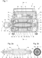
- FIG. 1 represents a section along the longitudinal axis AA of a high-speed centrifugal converter 1.
- the centrifugal converter comprises in a housing 2, a shaft 7 made of tungsten carbide or ceramic, mounted in rotation about a longitudinal axis AA passing through the front 2b and rear 2c faces, a first centrifugal compression wheel 8 and a second centrifugal compression wheel 10 mounted back to back at each end of the shaft 7, said first compression wheel 8 constituting a first compression stage and said second compression wheel 10 constituting a second compression stage. compression 10 constituting a second compression stage.
- the shaft 7 is hollow in this embodiment and contains a threaded rod 11, at each end of which is screwed one of the compression wheels 8, 10, which allows easy assembly and disassembly of the compression wheels.
- the two compression wheels 8 and 10 are driven on the same shaft 7, which allows for better energy efficiency and avoids a reducer.
- the rear of the compression wheels 8 and 10 has a labyrinth seal in order to control the pressures in the compressor and balance the axial forces.
- the casing 2 also contains a preferably synchronous electric motor positioned between the first compression wheel 8 and the second compression wheel 10 and arranged to rotate the shaft 7.
- the motor comprises a stator 14 and a rotor structure 16 which interact to form a synchronous electric motor with at least one permanent magnet 16a (brushless motor). More particularly, the stator 14 is formed by a coil 14a and two ferrite elements 14b, fixedly mounted relative to the casing 2.
- the rotor structure 16 comprises one or more permanent magnets 16a secured to the shaft 7, for example by gluing, and is covered with a titanium liner 16b. Titanium flanges 16c are fixed (for example by gluing) to the lateral ends of the liner and make it possible to ensure the resistance of the rotor to centrifugal forces at high speeds.
- the shaft 7 is rotatably mounted in the casing 2 about its longitudinal axis AA by means of at least one front radial bearing 18, one rear radial bearing 22 and one axial bearing 24, which is an integral part of the shaft 7.
- the centrifugal compressor 1 comprises a front radial bearing support 26 for supporting the front radial bearing 18, a rear radial bearing support 28 for supporting the rear radial bearing 22, arranged to be positioned around the shaft 7, respectively at the front and at the rear of the engine.
- a volute 29 is also provided between the rear radial bearing support 28 and the rear cover 3c.
- the volute 29 comprises the orifice leading to the tangential outlet 6 of fluid, after compression.
- An axial bearing support 30 is also provided to carry the axial bearing 24 arranged to be positioned around the shaft 7, between the first compression wheel 8 and the front radial bearing support 26. It is obvious that the axial bearing could be provided at the rear of the engine.
- the bearings are non-contact, aerodynamic type, in order to generate little friction. They do not require lubrication and require very little maintenance. More specifically, with reference to the Figures 2a, 2b , 3, 4 and 5 , the axial bearing 24 is an aerodynamic bearing. According to the present invention, it is part of the shaft 7 as such, that is to say that it is produced at the same time and in the same base material as the shaft 7 to form only one part with the shaft 7 in monobloc form at the end of its production.
- This axial bearing is constituted by a disk comprising on at least one of its faces first grooves 24a, preferably spiral on an annular zone at the periphery, arranged to create an air film.
- the axial bearing 24 comprises grooves or ribs 24a preferably spiral on the periphery of the axial bearing disk 24 on a front face and on a rear face obtained by a machining method explained below with reference to Figures 4 and 5 .
- the orientation of the grooves or ribs 24a may be different on the front face compared to the rear face or possibly identical.
- the axial bearing 24 with its grooves or ribs 24a makes it possible to keep the shaft 7 rotating in a longitudinally centered manner by generating air films on the front face and the rear face.
- the front 18 and rear 22 radial bearings are aerodynamic bearings, and the shaft 7 has, opposite the front 18 and rear 22 radial bearings, second grooves or ribs 32 arranged to create a film of air or gas when the shaft is rotated in the air or gas radial bearings.
- first centrifugal compression wheel 8 and the second centrifugal compression wheel 10 mounted back to back at each end of the shaft 7.
- a rotor structure 16 with at least one permanent magnet 16a of an electric motor is mounted or fixed for example on or in a central part of the shaft 7, to drive the shaft in rotation about the longitudinal axis AA, and an axial air or gas bearing 24 forming part of the shaft 7.
- a front radial air or gas bearing 18 is mounted on a first end of the shaft 7, and a rear radial air or gas bearing 22 is mounted on a second end of the shaft 7, as shown in FIG. Figure 2a .
- the rotor structure 16 with at least one permanent magnet 16a is fixed on the shaft 7 in a central position for the electric motor.
- FIG 3 shows a three-dimensional view of the shaft 7 with the axial bearing 24 at a first end of the shaft 7.
- a first portion of ribs or grooves 32 can be seen with the first radial bearing 18 shown in elevation above the ribs or grooves 32, and a second portion of ribs or grooves 32 with the second radial bearing 22 shown in elevation above these ribs or grooves 32.
- Ribs or grooves 24a are also shown on one face of the disc of the axial air or gas bearing 24 forming part of the shaft 7.
- the ribs or grooves 24a of a certain determined depth are made on an annular zone starting from the periphery of the disc and towards the centre of the disc.
- the ribs or grooves 24a and their arrangement are programmed in particular in the machining machine to activate the machining tool in order to produce all the ribs or grooves at once, that is to say by moving the tool holder, or the rotating disk in a single machining direction for example of the periphery of the disc at the bottom of the annular area of the ribs or grooves.
- Starting for example from the periphery of the disc on one of the faces and progressively portions of grooves are formed by back and forth movements of the machining tool in synchronism with the machining machine rotating the disc at a speed determined according to a sinusoidal programming.
- each start of all the grooves 24a is made by the rotation of the disk and the reciprocating movements of the machining tool. This is repeated continuously for the following groove or rib portions continuously from the first portion of the grooves and this until the end or bottom of the annular zone.
- the machining time per groove face of the disk is achieved in less than one minute, which differs significantly from previous machining carried out by laser beam.
- the machining machine is programmed to have a simultaneous synchronization of turning of the shaft 7 with the machining tool according to a sinusoidal programming to obtain a determined arrangement of the ribs or grooves 32 on the first portion to be machined of the shaft 7 for the front radial air or gas bearing 18.
- a sinusoidal programming to obtain a determined arrangement of the ribs or grooves 32 on the first portion to be machined of the shaft 7 for the front radial air or gas bearing 18.
- the determined arrangement of the ribs or grooves 32 made on the first portion of the first end of the shaft 7 is programmed in the machining machine.
- the ribs or grooves 32 each have a V shape, i.e. with a change of orientation in principle from the middle of the first portion of the shaft 7 to be machined. This makes it possible to maintain without mechanical contact the shaft rotated at high speed in the compressor in the air or gas radial bearings.
- the air or gas pressure in each aerodynamic radial bearing is such that the shaft is no longer in mechanical contact with the static radial bearing, thus avoiding any mechanical friction.
- the compressor 1 comprises a casing 2, made of aluminum, the upper face 2a of which is closed by an upper cover 3a and the front 2b and rear 2c faces are closed respectively by a front cover 3b and by a rear cover 3c.
- the side faces 2d of the casing are joined at their base to form a bottom 2e having, in cross section, a U shape.
- the upper cover 3a is positioned on the side of the electronic components of the compressor. Thus, access to the electronic components integrated in the compressor is easy, access being via the upper cover 3a.
- the front and rear covers 3b, 3c are used to reach the inside of the compressor (motor, rotor, bearings, etc.).
- a seal is inserted between the upper face of the casing 2 and the upper cover 3a. This seal protects the electronic components against dust and moisture.
- the casing 2 has an inlet for the fluid to be compressed 5 provided on the front cover 3b and a tangential outlet for the compressed fluid 6 provided on one of the side faces of the casing 2.
- the casing 2 comprises an internal through housing extending coaxially to the longitudinal axis AA between the front face 2b and the rear face 2c of the casing 2 and receiving the front radial bearing support 26 and the front radial bearing 18, the motor and its rotor structure 16 fixed on the shaft 7, the rear radial bearing support 28 and the rear radial bearing 22, the second compression wheel 10 and the volute 29.
- the internal housing On the side of the front face 2b, the internal housing is closed by the front cover 3b which integrates the first compression wheel 8, the axial bearing support 30 and the axial bearing 24.
- the inner housing is closed by the rear cover 3c.
- At least one orifice for example the point referenced 57a, arranged to allow the fluid to be compressed circulating in the channels to enter the motor and circulate between the stator 14 and the rotor structure 16 and at least one orifice, for example the points referenced 57b, arranged to allow the fluid to be compressed to exit the motor and join said channels after having cooled the motor.
- At least one orifice is advantageously provided, for example the points referenced 59a on the figure 1 arranged to allow the fluid to be compressed circulating in the channels 54 to circulate near the axial 24, front radial 18 and rear radial 22 bearings, and at least one orifice corresponding for example to the same points referenced 57b arranged to allow the fluid to be compressed to join said channels 54 after having cooled said axial 24, front radial 18 and rear radial 22 bearings.
- the fluid to be compressed passes into the channels 54 through the compressor parts located along the longitudinal axis between the first compression stage and the second compression stage to reach the second compression stage.
- the fluid to be compressed when it passes between the inner wall 52 and the ferrite elements 14b of the motor, cools the latter and recovers the calories lost from the motor in order to increase its efficiency before entering the second compression stage.
- the orifices 57a, 57b, 59a make it possible to achieve a slight deviation of the flow so that the fluid to be compressed also circulates between the stator 14 and the rotor structure 16 and in the bearings to cool these elements and recover the heat losses at the motor and the heat losses due to friction in the bearings.
- the centrifugal compressor 1 allows very high rotation speeds to be achieved, between 100,000 rpm and 500,000 rpm. It allows the fluid compressed in the first compression stage to pass substantially throughout the system to recover all the waste heat, and in particular the heat lost at the engine, bearings and electronic components, in order to increase its efficiency before entering the second compression stage (as the temperature of the fluid to be compressed increases, its pressure also increases).
- the use of only the fluid to be compressed to cool the compressor, without the aid of an additional cooling circuit, as well as the arrangement of the electronic components in the compressor to have electronics integrated into the casing make it possible to obtain a very compact compressor.
- the compressor according to the invention therefore has a high rotation speed and a high compression ratio while occupying a restricted volume.
- a compressor according to the invention has a compression ratio greater than 3, and a power of the order of 4 kW for dimensions L ⁇ l ⁇ h in cm of the order of 14 x 8 x 11 for a weight of only 1.6 kg.
- the compressor according to the invention can be used with air or gas to supply fuel cells, or any other system which uses compressed air (industrial compressors, medical compressors, boat compressors, etc.).
- the compressor according to the invention can be used in a mobile HVAC (heating, ventilation, air conditioning and air conditioning) system, such as in electric, hybrid or hydrogen vehicles.
- a mobile HVAC heating, ventilation, air conditioning and air conditioning
- the centrifugal compressor can also be used in a stationary system with a refrigerant gas, such as a heat pump.
- the centrifugal compressor can also be used with natural gas.
- FIG. 4 represents a machining machine 100 for producing ribs or grooves on portions of the first end and the second end of the shaft 7, and also for producing ribs or grooves on a first face of the axial bearing disc 24 forming part of the shaft 7 or also on a second face of the axial bearing disc 24 forming part of the shaft 7.
- the machining machine 100 comprises a machining lathe 130 with two spindles 140 for holding the shaft 7 at both ends of the shaft 7 and rotating it when machining the ribs or grooves at a determined rotational speed ⁇ .
- a first spindle 140 is located on a first vertical column or wall 102 of the machining machine 100, while the second spindle 140 is located on a second vertical column or wall 103 opposite the first vertical column or wall 102.
- the two vertical walls 102, 103 of the machining machine 100 are connected by a base 101 in which is arranged a means for guiding at least one tool holder 160 capable of carrying at least one machining tool 120 or two machining tools 120, 121 or several other different machining tools.
- the guiding means of the tool holder 160 in the base 101 of the machining machine 100 can be moved in a longitudinal direction A-A on one or two guide rails, for example not shown, in the base 101.
- the tool holder 160 can be moved parallel and preferably horizontally to the shaft 7 so as to place the first machining tool 120 in a machining position as already explained above.
- the first machining tool 120 is oriented perpendicular to the portion of the shaft 7 so as to be able to carry out the machining of the ribs or grooves on one of the portions to be machined of the shaft 7.
- the tool holder 160 is again moved parallel to the shaft 7 to move towards the second portion of the shaft to be machined.
- a second machining tool 121 fixed to the same tool holder 160 than the first machining tool 120, or to another tool holder not shown, but oriented in a direction perpendicular to the direction of the first machining tool.
- This second machining tool 121 can be used to carry out the machining of the ribs or grooves on at least one face of the axial bearing disc 24 forming part of the shaft 7. To do this, the tool holder 160 is moved parallel to the shaft 7 to the axial bearing disc 24. Once positioned near the disc, the second machining tool 121 is driven for the machining of the ribs or grooves on at least one of the faces of the axial bearing disc 24.
- the pins 140 which keep the shaft 7 rotating, can move in a longitudinal machining direction for producing the ribs or grooves.
- the shaft 7 is in tubular form so that it can be fixed and moved in a longitudinal direction. With the shaft 7 in tubular form, this allows the two pins 140 to have their ends partially inserted into the inner tube of the shaft at both ends of the shaft to keep it blocked and rotate it at a determined rotational speed ⁇ for machining.
- the two pins 140 with the shaft 7 to be machined can move in a longitudinal direction during the machining operation.
- the machining machine 100 further comprises at least one tool holder 160, which is connected to the structure of the machining lathe 130.
- the tool holder 160 carries a first machining tool 120 whose machining head can come into contact with the shaft 7 to machine the grooves or ribs can perform reciprocating movements according to a programming of the machining machine 100.
- At least the end of the head of the first machining tool 120 can be made of diamond to machine the ribs or grooves on the shaft 7 in tungsten carbide or ceramic.
- the tool holder 160 with the first machining tool 120 can also in an alternative embodiment be moved together in a longitudinal machining direction instead of the shaft 7 for machining ribs or grooves on the shaft.
- the back-and-forth movements of the first machining tool 120 may also be provided to modify the frequency of the back-and-forth movements of the first machining tool 120 according to programming carried out in the machining machine 100.
- the back-and-forth movements of the machining tool are synchronized by sinusoidal programming carried out in the machining machine, as well as to the desired and programmed arrangement of the ribs or grooves to be produced on the portion of the shaft 7 and/or the disk of the axial bearing 24 of the shaft 7.
- the axial bearing 24 of the shaft 7 is made with the shaft 7 in the same material in the monobloc form.
- the shaft 7 and the axial bearing 24 of the shaft can therefore be made at the same time either by a molding operation depending on the material used, or preferably by using at least one machining tool of a tool holder of the machining machine 100, which is subsequently used for machining the grooves or ribs on the front and rear portions of the shaft 7. In this case, it is possible to use the first machining tool 120 of the tool holder 160.
- this blank initial of the shaft 7, which may already be in tubular form may initially have a diameter corresponding substantially to the final external diameter of the axial bearing 24 to be produced.
- the blank is fixed to the two spindles 140 of the machining machine 100 to be driven in rotation about a longitudinal axis.
- the first machining tool 120 which must be of a more significant abrasive material, harder than the material of the blank of the shaft 7, and moved from a first end of the rotating shaft to a first position of the shaft 7 corresponding to the position of a face of the disk of the axial bearing 24 to be produced.
- this first machining operation there is the blank of the rotating shaft, as well as the machining tool 120 to be able to remove a first thin layer of material from the blank of the shaft.
- machining must also be carried out by removing thin layers on the other side of the shaft blank by changing the direction of the tubular blank to fix the shaft blank to the two spindles 140 in an opposite direction and repeating the operations with the machining tool 120 on its tool holder 160 as before. It is thus easier to change the direction of the shaft blank between the spindles 140, than to have to move the tool holder 160 with the machining tool 120 from another location on the machining machine 100.
- the ribs or grooves on the front and rear portions of the shaft can be machined using the first machining tool 120 connected to the tool holder 160.
- the shaft 7 to be machined is made of tungsten carbide or ceramic.
- the machining tool 120 generally comprises a head diamond machining. This makes it possible to produce all the ribs or grooves on a first portion to be machined of the first end of the shaft 7 from the start of the first portion to the end of the first portion at once by reciprocating movements of the machining tool 120 and movement in a longitudinal machining direction of the rotating shaft 7 according to the programming of the machining machine 100 or also by longitudinal movement of the first tool holder 160, or of the first tool 120 in the tool holder 160.
- a second machining tool 121 must be provided mounted on the tool holder 160 in a direction perpendicular to the first machining tool 120 to produce the ribs or grooves on one face of the disk of the axial bearing 24, or on both faces of the disk by a change in direction of the shaft 7 fixed between the two spindles 140.
- the machining of the ribs or grooves on a first portion before a second rear portion successively of the shaft can be carried out by the first machining tool 120.
- a change in orientation of the ribs or grooves can occur when passing half of the first portion to be machined and the second portion to be machined of the shaft 7 according to a programming of the machining machine so as to obtain V-shaped grooves over the length of the first and second machined portions in order to generate air or gas pressure in a front radial bearing arranged on the first portion or in a rear radial bearing arranged on the second portion during operation of the compressor with the rotation of the shaft 7 above a limit speed so as to no longer have mechanical contact with the front and rear radial bearing(s).
- the second machining tool 121 For machining the axial bearing 24, which is in the form of a disc, only the second machining tool 121 is used, which can be mounted on the tool holder 160 which can be moved longitudinally along the axis AA.
- the ribs or grooves and their arrangement are programmed into the machine.
- machining tool 100 to activate the second machining tool 121 to produce all the ribs or grooves at once on a first face of the disk by moving the machining tool, or the disk rotated in a single machining direction from the periphery of the disk to the bottom of the annular area of the ribs or grooves or vice versa, and by back-and-forth movements of the machining tool 121 according to the programming of the machining machine 100.
- the two faces of the disk of the axial bearing 24 can be machined by the second machining tool by switching the direction of the shaft 7 between the two spindles 140.
- the ribs or grooves may be made in the form of a spiral in the same orientation on both faces or two different orientations in order to generate air films through the grooves when the shaft 7 rotates to maintain the axis in a well-centered longitudinal position during operation of the centrifugal compressor.
- both the first machining tool 120 and the second machining tool 121 can be moved in the tool holder 160 in a first direction or in a second reverse direction to come into contact with a portion of the shaft 7 to be machined for the first machining tool 120 or to move away from it as symbolically shown by the arrows in the tool holder 160 or in each of the machining tools 120, 121.
- FIG. 5 is partly taken from the figure 4 of the machining machine 100.
- this tool holder 160 is movable longitudinally for example on one or more guide rails arranged in the base 101 of the machining machine 100.
- This second embodiment of the machining machine 100 seems easier to use than the first embodiment presented above at figure 4 , but without necessarily being more rapid in obtaining the ribs or grooves on the portions of the shaft 7 and on the disc of the axial bearing 24. All the elements presented in this figure 5 , which are identical to the elements described with reference to the figure 4 are therefore not repeated.
- the tool holder 160 may be provided with more than two machining tools, but with only one machining tool in operation for machining the ribs or grooves on one or two portions of the shaft 7 or on one face or two faces of the axial bearing disc 24.
Landscapes
- Engineering & Computer Science (AREA)
- Mechanical Engineering (AREA)
- General Engineering & Computer Science (AREA)
- Physics & Mathematics (AREA)
- Fluid Mechanics (AREA)
- Ocean & Marine Engineering (AREA)
- Structures Of Non-Positive Displacement Pumps (AREA)
- Sliding-Contact Bearings (AREA)
- Turning (AREA)
Abstract
Description
- L'invention se rapporte à un procédé d'usinage de nervures ou rainures d'un arbre pour des paliers à air ou à gaz d'un compresseur centrifuge de fluide à haute vitesse. Le compresseur est à deux étages, et comprend un carter avec une entrée de fluide et une sortie de fluide comprimé et renferme un arbre monté en rotation autour d'un axe longitudinal. Une première roue de compression et une seconde roue de compression sont montées dos à dos sur l'arbre, la première roue de compression constituant un premier étage de compression et la seconde roue de compression constituant un second étage de compression. Le compresseur centrifuge comprend encore un moteur, de préférence électrique synchrone, positionné entre la première roue de compression et la seconde roue de compression et agencé pour mettre en rotation l'arbre. Au moins un palier axial à air ou à gaz fait partie de l'arbre et est disposé à une extrémité de l'arbre. De plus, un palier radial avant à air ou à gaz peut être monté sur une première extrémité de l'arbre et un palier radial arrière à air ou à gaz peut être monté sur une seconde extrémité de l'arbre.
- Des compresseurs de fluide sont généralement appelés des turbocompresseurs ou compresseurs centrifuges. Ils comprennent un stator et un rotor formant un moteur synchrone à aimant permanent (moteur brushless). Ils peuvent atteindre de très hautes vitesses, telles que 100 000 à 500 000 tours/minute. Le moteur entraîne les roues de compression à régime élevé, où les roues de compression compriment le fluide. Le fluide peut être de l'air, un gaz, un réfrigérant ou tout autre fluide approprié. L'utilisation de deux roues de compression permet de comprimer le fluide deux fois plus.
- Ces compresseurs peuvent être utilisés par exemple dans un système CVCA (chauffage, ventilation, climatisation et conditionnement d'air) mobile avec un gaz frigorigène comme dans les véhicules électriques, hybrides ou à hydrogène. Ces compresseurs peuvent également être utilisés dans un système immobile avec un gaz frigorigène comme une pompe à chaleur.
- Ces compresseurs comprennent généralement un premier circuit pour la circulation du fluide à comprimer et un second circuit pour la circulation d'un liquide de refroidissement utilisé pour refroidir le compresseur, et plus particulièrement le moteur et les paliers à air ou à gaz supportant l'arbre du moteur d'une part et les composants électroniques d'autre part. En effet, la rotation à vitesse élevée du moteur entraîne un échauffement très important, de sorte que les éléments du compresseur doivent être refroidis pour ne pas être endommagés. Ces circuits sont généralement prévus à l'intérieur du compresseur en tant que tel, au moins en ce qui concerne le circuit de refroidissement. Rien n'est prévu pour faciliter l'écoulement de l'air ou le gaz de refroidissement lors du fonctionnement du compresseur notamment à haute vitesse, ce qui constitue un inconvénient. De plus, les paliers à air ou à gaz supportant l'arbre rotor ne sont pas conçus pour supporter l'arbre rotor sans frottement, ce qui génère un échauffement important lorsque le rotor tourne à haute vitesse ce qui constitue un autre inconvénient.
- De plus, il est connu de réaliser des rainures ou des nervures au niveau des paliers à air ou à gaz pour un écoulement de l'air ou de gaz, et permettre la création d'une pression et d'un refroidissement. Cependant, les rainures sont réalisées sans agencement particulier par un usinage laser, ce qui constitue un inconvénient, car le temps d'usinage est trop long et ainsi les coûts sont trop élevés.
- L'invention a notamment pour objectif de pallier les différents inconvénients mentionnés ci-dessus par un procédé pour réaliser rapidement des rainures ou des nervures sur un arbre de rotor pour des paliers à air ou à gaz, dont un palier axial à air ou à gaz fait partie de l'arbre. Lesdites rainures ou nervures sur l'arbre sont agencées de telle manière à vaincre la gravité lorsque l'arbre du compresseur tourne à haute vitesse dans chaque palier et pour permettre d'avoir l'arbre rotor en rotation maintenu sans contact mécanique sur un filet d'air ou de gaz dans les paliers radiaux donc pratiquement sans frottement.
- A cet effet, la présente invention concerne un procédé d'usinage de nervures ou rainures sur un arbre destiné à être mis en rotation autour d'un axe longitudinal d'un compresseur centrifuge, et/ou sur un palier axial à air ou à gaz faisant partie de l'arbre, qui comprend les caractéristiques de la revendication indépendante 1.
- Des étapes particulières du procédé sont définies dans les revendications dépendantes 2 à 10.
- Un avantage du procédé d'usinage des nervures ou rainures sur l'arbre et/ou le palier axial de l'arbre à usiner du compresseur dans une machine d'usinage, réside dans le fait que toutes les nervures ou rainures sont obtenues sur une portion à usiner de l'arbre entraîné en rotation, en une fois par un outil d'usinage effectuant des mouvements de va-et-vient du début à la fin de la portion à usiner de l'arbre. Pour ce faire, les mouvements de va-et-vient de l'outil d'usinage sont synchronisés à la programmation sinusoïdale effectuée dans la machine d'usinage, ainsi qu'à l'agencement désiré des nervures ou rainures à réaliser sur la portion de l'arbre.
- Un avantage du procédé d'usinage des nervures ou rainures sur le palier axial de l'arbre à usiner du compresseur dans une machine d'usinage, réside dans le fait que toutes les nervures ou rainures sont obtenues sur une ou deux faces du disque du palier axial de l'arbre entraîné en rotation,
- Durant l'usinage de l'arbre et/ou du palier axial de l'arbre, l'arbre ou le porte-outil portant l'outil d'usinage est également déplacé dans une direction longitudinale d'usinage pendant que l'outil d'usinage effectue les mouvements de va-et-vient.
- Les mouvements de va-et-vient de l'outil sont comparés à un oscillateur piézoélectrique où la fréquence d'oscillation peut être modifiée pour accélérer ou ralentir les mouvements de va-et-vient de l'outil selon la programmation effectuée dans la machine d'usinage pour obtenir lesdites nervures ou rainures désirées. Dans les mouvements de va-et-vient, l'outil est une fois en position d'usinage en contact avec l'arbre ou le palier axial de l'arbre et une autre fois sans contact avec l'arbre ou le palier axial de l'arbre.
- L'arbre à usiner est fixé à une structure rotor d'un moteur électrique l'entraînant en rotation, et au moins un palier axial à air ou à gaz, qui fait partie de l'arbre et qui est disposé à une première extrémité de l'arbre entre une roue de compression et un palier radial à air ou à gaz. Des nervures ou rainures peuvent être réalisées sur une face ou de préférence sur deux faces du disque du palier axial à air ou à gaz par un outil spécifique à l'usinage des nervures ou rainures du palier axial. Cependant, il peut être utilisé un même outil d'usinage pour l'usinage des nervures ou rainures sur des portions de l'arbre pour les paliers radiaux et sur une ou deux faces du disque du palier axial à air ou à gaz.
- Un avantage du procédé d'usinage des nervures ou rainures dans une machine d'usinage, réside dans le fait que les nervures ou rainures sont réalisées très rapidement en moins de 1 minute sur chaque portion à usiner de l'arbre pour les paliers radiaux à air ou à gaz et avec grande précision. Il en est de même pour les rainures ou nervures réalisées sur une ou deux faces du disque du palier axial à air ou à gaz entraîné en rotation. L'outil d'usinage est de plus grande dureté que le matériau de l'arbre ou du palier axial à air ou à gaz.
- Comme expliqué ci-dessus, la machine d'usinage peut être programmée pour avoir une synchronisation simultanée de tournage avec l'outil d'usinage selon une programmation sinusoïdale pour obtenir un agencement des nervures ou rainures sur chaque portion à usiner de l'arbre pour chaque palier radial à air ou à gaz, et pour le palier axial à air ou à gaz.
- Suite à un tel usinage des nervures ou rainures, qui sont de préférence en forme de V avec un changement d'orientation de chaque nervure ou rainure au centre de chaque portion usinée sur l'arbre, cela permet de maintenir sans contact mécanique l'arbre mis en rotation à haute vitesse dans le compresseur dans les paliers radiaux à air ou à gaz. Donc l'arbre est maintenu dans chaque palier radial pratiquement sans frottement par la pression de l'air ou de gaz passant dans les rainures ou nervures suite à la rotation à haute vitesse de l'arbre. Déjà à partir de 6000 tours/min, la pression d'air ou de gaz dans chaque palier radial aérodynamique est telle que l'arbre n'est plus en contact mécanique avec le palier radial statique évitant de ce fait tout frottement mécanique. Bien entendu plus l'arbre tourne vite, et plus la pression d'air est forte dans le palier radial, ce qui génère automatiquement un frottement d'air ou de gaz plus important.
- Les rainures ou nervures sont usinées par la machine d'usinage et l'outil d'usinage selon une programmation sinusoïdale et l'agencement désiré des rainures ou nervures de telle manière à avoir une inversion d'orientation des rainures ou nervures sur l'arbre pratiquement vers la moitié intérieure de chaque palier radial statique placé au-dessus desdites nervures. Cela permet de générer une pression d'air ou de gaz qui peut être de plus en plus importante plus l'arbre tourne vite.
- Un tel compresseur centrifuge de fluide à haute vitesse peut tourner à très haute vitesse sans un échauffement excessif grâce à la réalisation des nervures ou rainures dans les paliers radiaux à air ou à gaz.
- Un palier axial est également prévu entre la première roue de compression et le premier palier radial. Des rainures ou nervures sont pratiquées en périphérie sous forme de spirales sur une face avant et une face arrière du disque du palier axial. Des films d'air sont générés par les rainures à la rotation de l'arbre pour maintenir l'axe dans une position bien centrée longitudinalement.
- Les buts, avantages et caractéristiques de la présente invention apparaîtront plus clairement dans la description détaillée suivante d'une forme de réalisation de l'invention donnée uniquement à titre d'exemple non limitatif et illustrée par les dessins annexés sur lesquels :
- la
figure 1 représente une vue en coupe longitudinale selon l'axe A-A d'un compresseur centrifuge à haute vitesse selon l'invention, - les
figures 2a et 2b représentent une vue en coupe longitudinale selon l'axe A-A de l'arbre avec les roues de compression, les paliers aérodynamiques axial et radiaux et la structure rotor à aimants permanents, et une vue en plan du côté de la première roue de compression et le palier axial faisant partie de l'arbre selon l'invention, - la
figure 3 représente une vue tridimensionnelle de l'ensemble desfigures 2a et 2b montrant les rainures ou nervures dans chaque palier radial statique montré en élévation au-dessus de l'arbre selon l'invention et sur le palier axial faisant partie de l'arbre, - la
figure 4 est une vue en coupe longitudinale d'une machine d'usinage pour l'usinage des rainures ou nervures avec un premier d'ensemble d'usinage sur un palier axial à air ou à gaz faisant partie de l'arbre du compresseur et pour l'usinage des rainures ou nervures avec un second ensemble d'usinage sur deux portions de l'arbre pour les paliers radiaux selon l'invention, et - La
figure 5 est une vue en coupe longitudinale d'une variante de réalisation d'une machine d'usinage pour l'usinage des rainures ou nervures avec un seul ensemble d'usinage sur un palier axial à air ou à gaz faisant partie de l'arbre du compresseur et pour l'usinage des rainures ou nervures sur deux portions de l'arbre pour les paliers radiaux selon l'invention. - Dans la présente description, tous les composants faisant partie du compresseur centrifuge, qui sont bien connus de l'état de la technique, ne sont décrits que sommairement, car l'invention porte essentiellement sur la manière de réaliser des nervures ou des rainures sur deux portions d'un arbre pour être recouvertes respectivement par deux paliers radiaux statiques à air ou à gaz, ou sur un palier axial à air ou à gaz faisant partie de l'arbre.
- La
figure 1 représente une coupe selon l'axe longitudinal A-A d'un convertisseur centrifuge 1 à haute vitesse. Le convertisseur centrifuge comprend dans un carter 2, un arbre 7 en carbure de tungstène ou en céramique, monté en rotation autour d'un axe longitudinal A-A traversant les faces avant 2b et arrière 2c, une première roue de compression centrifuge 8 et une seconde roue de compression centrifuge 10 montées dos à dos à chaque extrémité de l'arbre 7, ladite première roue de compression 8 constituant un premier étage de compression et ladite seconde roue de compression 10 constituant un second étage de compression. Plus particulièrement, l'arbre 7 est creux dans cette forme d'exécution et renferme une tige filetée 11, à chaque extrémité de laquelle est vissée l'une des roues de compression 8, 10, ce qui permet un montage et un démontage aisés des roues de compression. Ainsi, les deux roues de compressions 8 et 10 sont entrainées sur le même arbre 7, ce qui permet d'avoir un meilleur rendement énergétique et d'éviter un réducteur. L'arrière des roues de compression 8 et 10 comporte un joint labyrinthe afin de maitriser les pressions dans le compresseur et équilibrer les forces axiales. - Le carter 2 renferme également un moteur électrique de préférence synchrone positionné entre la première roue de compression 8 et la seconde roue de compression 10 et agencé pour mettre en rotation l'arbre 7. Le moteur comprend un stator 14 et une structure rotor 16 qui interagissent pour former un moteur électrique synchrone à au moins un aimant permanent 16a (moteur brushless). Plus particulièrement, le stator 14 est formé par une bobine 14a et deux éléments en ferrite 14b, montés fixes par rapport au carter 2. La structure rotor 16 comprend un ou plusieurs aimants permanents 16a rendus solidaire de l'arbre 7, par exemple par collage, et est recouvert d'un chemisage 16b en titane. Des flasques en titane 16c sont fixées (par exemple par collage) aux extrémités latérales du chemisage et permettent d'assurer la résistance du rotor aux forces centrifuges lors de grandes vitesses.
- L'arbre 7 est monté en rotation dans le carter 2 autour de son axe longitudinal A-A au moyen d'au moins un palier radial avant 18, un palier radial arrière 22 et un palier axial 24, qui fait intégralement partie de l'arbre 7. Le compresseur centrifuge 1 comprend un support de palier radial avant 26 pour porter le palier radial avant 18, un support de palier radial arrière 28 pour porter le palier radial arrière 22, agencés pour se positionner autour de l'arbre 7, respectivement à l'avant et à l'arrière du moteur. A l'arrière, il est également prévu une volute 29 entre le support de palier radial arrière 28 et le couvercle arrière 3c. La volute 29 comprend l'orifice menant à la sortie tangentielle 6 de fluide, après compression. Il est également prévu un support de palier axial 30 pour porter le palier axial 24 agencé pour se positionner autour de l'arbre 7, entre la première roue de compression 8 et le support de palier radial avant 26. Il est bien évident que le palier axial pourrait être prévu à l'arrière du moteur.
- Les paliers sont sans contact, de type aérodynamiques, afin d'engendrer peu de frottement. Ils ne nécessitent pas de lubrification et demandent très peu de maintenance. Plus particulièrement, en référence aux
figures 2a, 2b ,3, 4 et 5 , le palier axial 24 est un palier aérodynamique. Selon la présente invention, il fait partie de l'arbre 7 en tant que tel, c'est-à-dire qu'il est réalisé en même temps et dans le même matériau de base que l'arbre 7 pour ne former qu'une pièce avec l'arbre 7 sous forme monobloc au terme de sa réalisation. - Ce palier axial est constitué par un disque comportant sur au moins l'une de ses faces des premières rainures 24a, de préférence en spirale sur une zone annulaire en périphérie, agencées pour créer un film d'air. De préférence, le palier axial 24 comprend des rainures ou nervures 24a de préférence en spirale en périphérie du disque de palier axial 24 sur une face avant et sur une face arrière obtenues par un procédé d'usinage expliqué ci-après en référence aux
figures 4 et 5 . L'orientation des rainures ou nervures 24a peut être différente sur la face avant par rapport à la face arrière ou éventuellement identique. Le palier axial 24 avec ses rainures ou nervures 24a permet de garder l'arbre 7 en rotation de manière centrée longitudinalement par la génération de films d'air de la face avant et de la face arrière. Les paliers radiaux avant 18 et arrière 22 sont des paliers aérodynamiques, et l'arbre 7 présente en regard des paliers radiaux avant 18 et arrière 22 des secondes rainures ou nervures 32 agencées pour créer un film d'air ou de gaz lorsque l'arbre est mis en rotation dans les paliers radiaux à air ou à gaz. - Aux
figures 2a et 2b , on peut remarquer encore la première roue de compression centrifuge 8 et la seconde roue de compression centrifuge 10 montées dos à dos à chaque extrémité de l'arbre 7. Une structure rotor 16 à au moins un aimant permanent 16a d'un moteur électrique est montée ou fixée par exemple sur ou dans une partie centrale de l'arbre 7, pour entraîner l'arbre en rotation selon l'axe longitudinal A-A, et un palier axial à air ou à gaz 24 faisant partie de l'arbre 7. Un palier radial avant 18 à air ou à gaz est monté sur une première extrémité de l'arbre 7, et un palier radial arrière 22 à air ou à gaz est monté sur une seconde extrémité de l'arbre 7, comme représenté à lafigure 2a . - Comme montré à la
figure 3 , aux deux extrémités de l'arbre 7 sont une première portion de nervures ou rainures 32 usinées et à l'autre extrémité une seconde portion de rainures ou nervures 32 usinées. La structure rotor 16 à au moins un aimant permanent 16a est fixée sur l'arbre 7 dans une position centrale pour le moteur électrique. - La
figure 3 représente une vue tridimensionnelle de l'arbre 7 avec le palier axial 24 à une première extrémité de l'arbre 7. Aux deux extrémités de l'arbre 7, on peut remarquer une première portion de nervures ou rainures 32 avec le premier palier radial 18 montré en élévation au-dessus des nervures ou rainures 32, et une seconde portion de nervures ou rainures 32 avec le second palier radial 22 montré en élévation au-dessus de ces nervures ou rainures 32. Des nervures ou rainures 24a sont représentées également sur une face du disque du palier axial 24 à air ou à gaz faisant partie de l'arbre 7. Les nervures ou rainures 24a d'une certaine profondeur déterminée sont réalisées sur une zone annulaire partant de la périphérie du disque et en direction du centre du disque. Les nervures ou rainures 24a et leur agencement sont programmés notamment dans la machine d'usinage pour activer l'outil d'usinage afin de réaliser toutes les nervures ou les rainures en une fois, c'est-à-dire en déplaçant le porte-outil, ou le disque mis en rotation dans une seule direction d'usinage par exemple de la périphérie du disque au bas de la zone annulaire des nervures ou rainures. En partant par exemple de la périphérie du disque sur une des faces et progressivement des portions de rainures se forment par des mouvements de va-et-vient de l'outil d'usinage en synchronisme avec la machine d'usinage faisant tourner le disque à une vitesse déterminée selon une programmation sinusoïdale. - Avec cette programmation et en combinaison aux mouvements de va-et-vient contrôlés de l'outil d'usinage, chaque début de toutes les rainures 24a est réalisé par la rotation du disque et les mouvements de va-et-vient de l'outil d'usinage. Ceci se répète continuellement pour les portions de rainures ou nervures suivantes en continu de la première portion des rainures et ceci jusqu'au terme ou au bas de la zone annulaire. Avec une telle manière de réaliser les différentes nervures ou rainures 24a sur le disque 24, le temps d'usinage par face à rainures du disque est réalisé en moins d'une minute, ce qui se différencie notablement d'un usinage précédent effectué par faisceau laser.
- La machine d'usinage est programmée pour avoir une synchronisation simultanée de tournage de l'arbre 7 avec l'outil d'usinage selon une programmation sinusoïdale pour obtenir un agencement déterminé des nervures ou rainures 32 sur la première portion à usiner de l'arbre 7 pour le palier radial avant à air ou à gaz 18. En partant par exemple du début de la première portion à usiner de l'arbre 7 du côté de sa première extrémité et dans une seule direction d'usinage et jusqu'à la fin de la première portion de la première extrémité de l'arbre 7, toutes les nervures ou rainures 32 sont toutes usinées en une fois, ce qui fait gagner beaucoup de temps d'usinage.
- L'agencement déterminé des nervures ou rainures 32 réalisées sur la première portion de la première extrémité de l'arbre 7 est programmé dans la machine d'usinage. Dans une forme d'exécution désiré, les nervures ou les rainures 32 ont chacune une forme de V, c'est-à-dire avec un changement d'orientation en principe depuis le milieu de la première portion de l'arbre 7 à usiner. Cela permet de maintenir sans contact mécanique l'arbre mis en rotation à haute vitesse dans le compresseur dans les paliers radiaux à air ou à gaz. Déjà à partir de 6000 tours/min, la pression d'air ou de gaz dans chaque palier radial aérodynamique est telle que l'arbre n'est plus en contact mécanique avec le palier radial statique évitant de ce fait tout frottement mécanique.
- En guise de complément dans la
figure 1 , le compresseur 1 comprend un carter 2, en aluminium, dont la face supérieure 2a est fermée par un couvercle supérieur 3a et les faces avant 2b et arrière 2c sont fermées respectivement par un couvercle avant 3b et par un couvercle arrière 3c. Les faces latérales 2d du carter sont réunies à leur base pour former un fond 2e présentant, en section transversale, une forme en U. - Le couvercle supérieur 3a est positionné du côté des composants électroniques du compresseur. Ainsi, l'accès aux composants électroniques intégrés dans le compresseur, est facile, l'accès se faisant par le couvercle supérieur 3a. Les couvercles avant et arrière 3b, 3c servent à atteindre l'intérieur du compresseur (moteur, rotor, paliers, etc.). Un joint d'étanchéité est intercalé entre la face supérieure du carter 2 et le couvercle supérieur 3a. Ce joint permet de protéger les composants électroniques contre la poussière et l'humidité.
- Le carter 2 présente une entrée de fluide à comprimer 5 prévue sur le couvercle avant 3b et une sortie tangentielle de fluide comprimé 6 prévue sur l'une des faces latérales du carter 2.
- A la
figure 1 , le carter 2 comprend un logement intérieur traversant s'étendant coaxialement à l'axe longitudinal A-A entre la face avant 2b et la face arrière 2c du carter 2 et recevant le support de palier radial avant 26 et le palier radial avant 18, le moteur et sa structure rotor 16 fixée sur l'arbre 7, le support de palier radial arrière 28 et le palier radial arrière 22, la seconde roue de compression 10 et la volute 29. Du côté de la face avant 2b, le logement intérieur est fermé par le couvercle avant 3b qui intègre la première roue de compression 8, le support de palier axial 30 et le palier axial 24. Du côté de la face arrière 2c, le logement intérieur est fermé par le couvercle arrière 3c. - En outre, il est prévu avantageusement au moins un orifice par exemple le point référencé 57a agencé pour permettre au fluide à comprimer circulant dans les canaux d'entrer dans le moteur et de circuler entre le stator 14 et la structure rotor 16 et au moins un orifice par exemple les points référencés 57b agencé pour permettre au fluide à comprimer de sortir du moteur et de rejoindre lesdits canaux après avoir refroidi le moteur.
- De même, il est prévu avantageusement au moins un orifice par exemple les points référencés 59a sur la
figure 1 agencé pour permettre au fluide à comprimer circulant dans les canaux 54 de circuler à proximité des paliers axial 24, radial avant 18 et radial arrière 22, et au moins un orifice correspondant par exemple aux mêmes points référencés 57b agencé pour permettre au fluide à comprimer de rejoindre lesdits canaux 54 après avoir refroidi lesdits paliers axial 24, radial avant 18 et radial arrière 22. - Ainsi, après être entré dans le premier étage de compression par l'entrée 5, le fluide à comprimer passe dans les canaux 54 à travers les pièces du compresseur situées le long de l'axe longitudinal entre le premier étage de compression et le deuxième étage de compression pour rejoindre le second étage de compression. De ce fait, le fluide à comprimer, lorsqu'il passe entre la paroi intérieure 52 et les éléments en ferrite 14b du moteur, refroidit ce dernier et récupère les calories perdues du moteur afin d'augmenter son efficacité avant d'entrer dans le second étage de compression. De plus, les orifices 57a, 57b, 59a permettent de réaliser une légère déviation du flux afin que le fluide à comprimer circule également entre le stator 14 et la structure rotor 16 et dans les paliers pour refroidir ces éléments et récupérer les pertes de chaleur au niveau du moteur et les pertes de chaleur dues aux frottements dans les paliers.
- Le compresseur centrifuge 1 permet d'atteindre des vitesses de rotation très élevées, comprises entre 100 000 tr/min et 500 000 tr/min. Il permet au fluide comprimé dans le premier étage de compression de passer sensiblement dans tout le système pour récupérer toute la chaleur perdue, et notamment la chaleur perdue au niveau du moteur, des paliers et des composants électroniques, afin d'augmenter son efficacité avant d'entrer dans le second étage de compression (la température du fluide à comprimer augmentant, sa pression augmente également). En outre, l'utilisation du seul fluide à comprimer pour refroidir le compresseur, sans l'aide d'un circuit de refroidissement additionnel, ainsi que l'agencement des composants électroniques dans le compresseur pour avoir une électronique intégrée au carter, permettent d'obtenir un compresseur très compact. Le compresseur selon l'invention présente donc un haut régime de rotation et un grand rapport de compression tout en occupant un volume restreint. Par exemple, un compresseur selon l'invention présente un rapport de compression supérieur à 3, et une puissance de l'ordre de 4 kW pour des dimensions L × l × h en cm de l'ordre de 14 x 8 x 11 pour un poids de 1,6 kg seulement.
- Par exemple le compresseur selon l'invention peut être utilisé avec de l'air ou du gaz pour l'alimentation de piles à combustible, ou tout autre système qui utilise de l'air comprimé (compresseurs industriels, compresseurs médicaux, de bateaux, etc.).
- Avec un gaz frigorigène, le compresseur selon l'invention peut être utilisé dans un système CVCA (chauffage, ventilation, climatisation et conditionnement d'air) mobile, comme dans les véhicules électriques, hybrides ou à hydrogène.
- Le compresseur centrifuge peut aussi être utilisé dans un système immobile avec un gaz frigorigène, comme une pompe à chaleur.
- Le compresseur centrifuge peut aussi être utilisé avec un gaz naturel.
- La
figure 4 représente une machine d'usinage 100 pour la réalisation de nervures ou rainures sur des portions de la première extrémité et de la seconde extrémité de l'arbre 7, et également pour la réalisation de nervures ou rainures sur une première face du disque du palier axial 24 faisant partie de l'arbre 7 ou également sur une seconde face du disque du palier axial 24 faisant partie de l'arbre 7. - La machine d'usinage 100 comprend un tour d'usinage 130 avec deux broches 140 pour maintenir l'arbre 7 aux deux extrémités de l'arbre 7 et le faire tourner lors de l'usinage des nervures ou rainures à une vitesse de rotation déterminée ω. Une première broche 140 se trouve sur une première colonne ou paroi verticale 102 de la machine d'usinage 100, alors que la seconde broche 140 se trouve sur une seconde colonne ou paroi verticale 103 à l'opposé de la première colonne ou paroi verticale 102. Les deux parois verticales 102, 103 de la machine d'usinage 100 sont reliées par une base 101 dans laquelle est disposée un moyen de guidage d'au moins un porte-outil 160 susceptible de porter au moins un outil d'usinage 120 ou deux outils d'usinage 120, 121 ou plusieurs autres outils d'usinage différents. Le moyen de guidage du porte-outil 160 dans la base 101 de la machine d'usinage 100, peut être déplacé dans une direction longitudinale A-A sur un ou deux rails de guidage par exemple non représentés dans la base 101.
- Pour l'usinage des nervures ou rainures sur la première portion avant ou la seconde portion arrière de l'arbre 7 placé entre les deux broches 140 et entraîné en rotation selon l'axe longitudinal A-A, le porte-outil 160 peut être déplacé parallèlement et de préférence de manière horizontale à l'arbre 7 de manière à placer le premier outil d'usinage 120 dans une position d'usinage comme déjà expliqué ci-dessus. Le premier outil d'usinage 120 est orienté perpendiculairement à la portion de l'arbre 7 de manière à pouvoir effectuer l'usinage des nervures ou des rainures sur une des portions à usiner de l'arbre 7. Puis par la suite le porte-outil 160 est à nouveau déplacé parallèlement à l'arbre 7 pour se diriger vers la seconde portion de l'arbre à usiner.
- Dans cette première variante de réalisation de la machine d'usinage 100, il peut être prévu un second outil d'usinage 121 fixé au même porte-outil 160 que le premier outil d'usinage 120, ou à un autre porte-outil non représenté, mais orienté dans une direction perpendiculaire à la direction du premier outil d'usinage. Ce second outil d'usinage 121 peut être utilisé pour aller réaliser l'usinage des nervures ou rainures sur au moins une face du disque du palier axial 24 faisant partie de l'arbre 7. Pour ce faire, le porte-outil 160 est déplacé parallèlement à l'arbre 7 jusqu'au disque du palier axial 24. Une fois positionné à proximité du disque, le second outil d'usinage 121 est entraîné pour l'usinage des nervures ou rainures sur au moins une des faces du disque du palier axial 24.
- Il est à noter que pour cette première variante de réalisation de la machine d'usinage, il est préféré d'utiliser un même porte-outil pour les deux outils d'usinage de manière à ne pas avoir de parties en porte-à-faux susceptibles de mener à un manque de précision de l'usinage. Avec un même porte-outil 160, on s'affranchit de toute erreur d'usinage cumulative de deux porte-outils à réglage non uniforme.
- Selon une variante de réalisation, les broches 140, qui maintiennent l'arbre 7 en rotation peuvent se déplacer dans une direction longitudinale d'usinage pour la réalisation des nervures ou rainures. Comme précédemment indiqué, l'arbre 7 est sous forme tubulaire de manière à pouvoir être fixé et déplacé dans une direction longitudinale. Avec l'arbre 7 sous forme tubulaire, cela permet aux deux broches 140 d'avoir leur extrémité s'insérer en partie dans le tube intérieur de l'arbre aux deux extrémités de l'arbre pour le maintenir bloqué et le faire tourner à une vitesse de rotation déterminée ω pour l'usinage. Bien entendu, les deux broches 140 avec l'arbre 7 à usiner peuvent bouger dans une direction longitudinale pendant l'opération d'usinage.
- Dans cette variante de réalisation, la machine d'usinage 100 comprend encore au moins un porte-outil 160, qui est relié à la structure du tour d'usinage 130. Bien entendu, les dimensions réelles de la machine d'usinage 100 sont présentées plus petites qu'en réalité. Le porte-outil 160 porte un premier outil d'usinage 120 dont la tête d'usinage peut venir en contact de l'arbre 7 pour usiner les rainures ou nervures peut effectuer des mouvements de va-et-vient selon une programmation de la machine d'usinage 100. Au moins l'extrémité de la tête du premier outil d'usinage 120 peut être en diamant pour usiner les nervures ou rainures sur l'arbre 7 en carbure de tungstène ou en céramique. Ceci est effectué pour avoir une synchronisation simultanée de tournage de l'arbre 7 avec le premier outil d'usinage 120 selon une programmation sinusoïdale pour obtenir un agencement déterminé des nervures ou rainures sur les portions à usiner de l'arbre 7 pour chaque palier radial avant ou arrière à air ou à gaz.
- Le porte-outil 160 avec le premier outil d'usinage 120 peuvent aussi dans une variante de réalisation être déplacés ensemble dans une direction longitudinale d'usinage à la place de l'arbre 7 pour l'usinage des nervures ou rainures sur l'arbre.
- Il peut encore être prévu de modifier la fréquence des mouvements de va-et-vient du premier outil d'usinage 120 selon une programmation effectuée dans la machine d'usinage 100. Notamment, les mouvements de va-et-vient de l'outil d'usinage sont synchronisés par une programmation sinusoïdale effectuée dans la machine d'usinage, ainsi qu'à l'agencement désiré et programmé des nervures ou rainures à réaliser sur la portion de l'arbre 7 et/ou du disque du palier axial 24 de l'arbre 7.
- Il est à noter que le palier axial 24 de l'arbre 7 est réalisé avec l'arbre 7 dans un même matériau sous la forme monobloc. L'arbre 7 et le palier axial 24 de l'arbre peuvent donc être réalisés en même temps soit par une opération de moulage en fonction du matériau utilisé, soit de préférence en utilisant au moins un outil d'usinage d'un porte-outil de la machine usinage 100, qui est utilisé par la suite pour l'usinage des rainures ou nervures sur les portions avant et arrière de l'arbre 7. Dans ce cas de figure, il est possible d'utiliser le premier outil d'usinage 120 du porte-outil 160. De plus pour réaliser le palier axial 24 sur une ébauche initiale de l'arbre 7, cette ébauche initiale de l'arbre 7, qui peut être déjà sous forme tubulaire, peut avoir initialement un diamètre correspondant sensiblement au diamètre final externe du palier axial 24 à réaliser. L'ébauche est fixée aux deux broches 140 de la machine usinage 100 pour être entraînée en rotation autour d'un axe longitudinal. Le premier outil d'usinage 120, qui doit être d'un matériau abrasif plus important, plus dur que le matériau de l'ébauche de l'arbre 7, et déplacé d'une première extrémité de l'arbre en rotation à une première position de l'arbre 7 correspondant à la position d'une face du disque du palier axial 24 à réaliser. Dans cette première opération d'usinage, il y a l'ébauche de l'arbre en rotation, ainsi que l'outil d'usinage 120 pour pouvoir retirer une première fine couche de matériau de l'ébauche de l'arbre. Par la suite, plusieurs autres fines couches successives sont retirées de l'arbre en rotation par l'outil d'usinage 120 par déplacement longitudinal de la première extrémité à la première position du palier axial 24 jusqu'à atteindre le diamètre de l'arbre désiré, et ainsi avoir le palier axial 24 réalisé sur l'arbre 7. Si une continuité de l'arbre part d'une seconde position du palier axial à l'extrémité opposée de l'arbre, il doit aussi être effectué l'usinage par retrait de fines couches de l'autre côté de l'ébauche de l'arbre en changeant de sens l'ébauche tubulaire pour fixer l'ébauche de l'arbre aux deux broches 140 dans une direction opposée et répéter les opérations avec l'outil d'usinage 120 sur son porte-outil 160 comme précédemment. Il est ainsi plus facile de changer de sens l'ébauche de l'arbre entre les broches 140, que de devoir déplacer le porte-outil 160 avec l'outil d'usinage 120 d'un autre endroit de la machine à usinage 100.
- Bien entendu au terme de la réalisation de l'arbre 7 au diamètre escompté et du palier axial 24, il peut être réalisé l'usinage des nervures ou rainures sur les portions avant et arrière de l'arbre par le premier outil d'usinage 120 relié au porte-outil 160.
- Généralement, l'arbre 7 à usiner est en carbure de tungstène ou en céramique. Ainsi l'outil d'usinage 120 comprend généralement une tête d'usinage en diamant. Cela permet de réaliser toutes les nervures ou rainures sur une première portion à usiner de la première extrémité de l'arbre 7 depuis le début de la première portion à la fin de la première portion en une fois par des mouvements de va-et-vient de l'outil d'usinage 120 et déplacement dans une direction longitudinale d'usinage de l'arbre 7 en rotation selon la programmation de la machine d'usinage 100 ou également par déplacement longitudinal du premier porte-outil 160, ou du premier outil 120 dans le porte-outil 160.
- Dans cette première forme d'exécution de la machine usinage 100, il doit être prévu un second outil d'usinage 121 monté sur le porte-outil 160 dans une direction perpendiculaire au premier outil d'usinage 120 pour réaliser les nervures ou rainures sur une face du disque du palier axial 24, ou sur les deux faces du disque par un changement de sens de l'arbre 7 fixé entre les deux broches 140.
- Il est à noter encore qu'il peut être réalisé l'usinage des nervures ou rainures sur une première portion avant une seconde portion arrière successivement de l'arbre par le premier outil d'usinage 120. Un changement d'orientation des nervures ou rainures peut intervenir au passage de la moitié de la première portion à usiner et de la seconde portion à usiner de l'arbre 7 selon une programmation de la machine d'usinage de manière à obtenir des rainures en forme de V sur la longueur des première et seconde portions usinées dans le but de générer une pression d'air ou de gaz dans un palier radial avant disposé sur la première portion ou dans un palier radial arrière disposé sur la seconde portion lors du fonctionnement du compresseur avec la rotation de l'arbre 7 au-dessus d'une vitesse limite pour ne plus avoir de contact mécanique avec le ou les paliers radiaux avant et arrière.
- Pour l'usinage du palier axial 24, qui est sous la forme d'un disque il est utilisé uniquement le second outil d'usinage 121, qui peut être monté sur le porte-outil 160 déplaçable longitudinalement selon l'axe A-A. Les nervures ou rainures et leur agencement sont programmés dans la machine d'usinage 100 pour activer le second outil d'usinage 121 afin de réaliser toutes les nervures ou les rainures en une fois sur une première face du disque en déplaçant l'outil d'usinage, ou le disque mis en rotation dans une seule direction d'usinage de la périphérie du disque au bas de la zone annulaire des nervures ou rainures ou inversement, et par des mouvements de va-et-vient de l'outil d'usinage 121 selon la programmation de la machine d'usinage 100. Les deux faces du disque du palier axial 24 peuvent être usinées par le second outil d'usinage en permutant de sens l'arbre 7 entre les deux broches 140.
- Sur une ou les deux faces du disque du palier axial 24, les nervures ou les rainures peuvent être réalisées sous la forme de spirale selon une même orientation sur les deux faces ou deux orientations différentes dans le but de générer des films d'air par les rainures à la rotation de l'arbre 7 pour maintenir l'axe dans une position bien centrée longitudinalement lors du fonctionnement du compresseur centrifuge.
- Il est encore à noter qu'aussi bien le premier outil d'usinage 120, que le second outil d'usinage 121 peuvent être déplacés dans le porte-outil 160 dans une première direction ou dans une seconde direction inverse pour venir en contact d'une portion de l'arbre 7 à usiner pour le premier outil d'usinage 120 ou s'en éloigner comme montrer symboliquement par les flèches dans le porte-outil 160 ou dans chacun des outils d'usinage 120, 121.
- La
figure 5 est reprise en partie de lafigure 4 de la machine usinage 100. Cependant dans ce cas de figure, il n'y a qu'un seul porte-outil 160 et également un seul outil d'usinage 120 susceptible d'être orienté ou déplacé en rotation autour d'un axe 150 du porte-outil 160 pour être dans une position indiquée (1) pour l'usinage des nervures ou rainures sur les portions avant et arrière de l'arbre 7, et dans une position indiquée (2) pour l'usinage des nervures ou rainures sur une face ou de préférence deux faces du disque du palier axial 24. - Comme pour le porte-outil 160 montré à la
figure 4 , ce porte-outil 160 est déplaçable longitudinalement par exemple sur un ou des rails de guidage disposés dans la base 101 de la machine d'usinage 100. - Cette seconde forme d'exécution de la machine usinage 100 semble plus facile d'utilisation que la première forme d'exécution présentée ci-dessus à la
figure 4 , mais sans être forcément d'une plus grande rapidité pour l'obtention des nervures ou rainures sur les portions de l'arbre 7 et sur le disque du palier axial 24. Tous les éléments présentés dans cettefigure 5 , qui sont identiques aux éléments décrits en référence à lafigure 4 ne sont donc pas répétés. Le porte-outil 160 peut être muni de plus de deux outils d'usinage, mais avec un seul outil d'usinage en fonction pour l'usinage des nervures ou rainures sur une ou deux portions de l'arbre 7 ou sur une face ou deux faces du disque du palier axial 24. - Bien entendu, la présente invention ne se limite pas aux exemples illustrés et est susceptible de diverses variantes et modifications qui apparaîtront de manière évidente à l'homme du métier. D'autres combinaisons sont bien entendues possibles avec déjà ce qui est connu avec le compresseur centrifuge. L'usinage rapide et précis de nervures ou rainures peut être effectué sur d'autres pièces que celles décrites ci-dessus avec des éléments d'usinage équivalents.
Claims (10)
- Procédé d'usinage de nervures ou rainures sur un arbre (7) destiné à être mis en rotation autour d'un axe longitudinal (A-A) d'un compresseur centrifuge (1), et/ou sur un palier axial à air ou à gaz (24) faisant partie de l'arbre (7), une structure rotor (16) à au moins un aimant permanent (16a) d'un moteur électrique étant destinée à être montée sur l'arbre (7) ou dans l'arbre (7) pour entraîner l'arbre en rotation, le compresseur centrifuge (1) comprenant encore un carter (2) présentant une entrée de fluide (5) et une sortie (6) de fluide comprimé, une première roue de compression (8) et une seconde roue de compression (10) destinées à être montées à deux extrémités de l'arbre (7) dans le carter (2), un palier radial avant (18) à air ou à gaz destiné à être monté sur une première extrémité de l'arbre (7), et/ou un palier radial arrière (22) à air ou à gaz destiné à être monté sur une seconde extrémité de l'arbre (7), le procédé d'usinage étant effectué dans une machine d'usinage (100) adaptée pour recevoir l'arbre (7) avec le palier axial (24) à usiner et comprenant un porte-outil (160) avec un outil d'usinage (120, 121) des nervures ou rainures sur au moins une portion de l'arbre (7) ou du palier axial (24) de l'arbre (7),
le procédé étant caractérisé en ce que toutes les nervures ou rainures (24a; 32) sont obtenues sur une portion à usiner de l'arbre entraînée en rotation et/ou du disque du palier axial (24) de l'arbre (7), par déplacement de l'arbre (7) et/ou du disque du palier axial (24) de l'arbre (7), ou du porte-outil (160) dans une direction longitudinale d'usinage, en une fois par l'outil d'usinage (120, 121) effectuant des mouvements de va-et-vient avec une position d'usinage en contact avec l'arbre (7) et/ou avec le disque du palier axial (24) de l'arbre (7), et une position sans contact avec l'arbre (7) et/ou avec le disque du palier axial (24) de l'arbre (7), du début à la fin de la portion à usiner avec l'arbre (7) et/ou avec le disque du palier axial (24) de l'arbre (7), et en ce que les mouvements de va-et-vient de l'outil d'usinage (120, 121) sont synchronisés à une programmation sinusoïdale effectuée dans la machine d'usinage (100), ainsi qu'à l'agencement désiré et programmé des nervures ou rainures à réaliser sur la portion de l'arbre (7) et/ou du disque du palier axial (24) de l'arbre (7). - Procédé d'usinage selon la revendication 1, pour lequel le palier axial à air ou à gaz (24) est réalisé sur l'arbre (7) avant l'usinage des nervures ou rainures (32) sur l'arbre (7).
- Procédé d'usinage selon la revendication 2, caractérisé en ce que le palier axial à air ou à gaz (24) est réalisé en prenant une ébauche d'un arbre (7) de diamètre sensiblement égal au diamètre désiré du palier axial (24) à réaliser, en ce que l'ébauche de l'arbre (7) est entraînée en rotation dans la machine d'usinage (100) autour d'un axe longitudinal (A-A), en ce qu'un outil d'usinage (120) à matériau abrasif est déplacé d'une extrémité de l'arbre (7) en rotation à une première position de l'arbre (7) correspondant à la position d'une face du disque du palier axial (24) à réaliser de manière à retirer une fine couche de matériau de l'arbre (7), en ce que plusieurs fines couches successives sont retirées de l'arbre (7) en rotation par l'outil d'usinage (120) par déplacement longitudinal de la première extrémité à la première position du palier axial (24) jusqu'à atteindre le diamètre de l'arbre (7) désiré.
- Procédé d'usinage selon la revendication 3, caractérisé en ce qu'une même opération d'usinage successif pour le retrait de fines couches est effectuée depuis l'extrémité opposée de l'arbre (7) jusqu'à une seconde position du palier axial correspondant à la seconde face du palier axial (24).
- Procédé d'usinage selon la revendication 1, pour lequel l'arbre (7) à usiner est en carbure de tungstène ou en céramique, et pour lequel la tête de l'outil d'usinage (120) est en diamant, caractérisé en ce que l'arbre (7) est entraîné en rotation durant l'usinage autour de l'axe longitudinal (A-A), en ce que toutes les nervures ou rainures (32) sont obtenues sur une première portion à usiner de la première extrémité de l'arbre (7) depuis le début de la première portion à la fin de la première portion en une fois par des mouvements de va-et-vient de l'outil d'usinage (120) et déplacement dans une direction longitudinale d'usinage de l'arbre (7) en rotation selon la programmation de la machine d'usinage (100).
- Procédé d'usinage selon la revendication 1, pour lequel l'arbre (7) à usiner est en carbure de tungstène ou en céramique, et pour lequel la tête de l'outil d'usinage (120) est en diamant, caractérisé en ce que l'arbre (7) est entraîné en rotation durant l'usinage autour de l'axe longitudinal (A-A), en ce que toutes les nervures ou rainures (32) sont obtenues sur une seconde portion à usiner de la seconde extrémité de l'arbre (7) depuis le début de la seconde portion à la fin de la seconde portion en une fois par des mouvements de va-et-vient de l'outil d'usinage (120) et déplacement dans une direction longitudinale d'usinage du porte-outil (160) selon la programmation de la machine d'usinage (100).
- Procédé d'usinage selon l'une des revendications 5 et 6, caractérisé en ce que lors de l'usinage des nervures ou rainures (32), un changement d'orientation des nervures ou rainures (32) intervient au passage de la moitié de la première portion à usiner de la première extrémité de l'arbre (7) et au passage de la moitié de la seconde portion à usiner de la seconde extrémité de l'arbre (7) selon une programmation de la machine d'usinage de manière à obtenir des rainures en forme de V sur la longueur des première et seconde portions usinées dans le but de générer une pression d'air ou de gaz dans un palier radial avant (18) disposé sur la première portion ou dans un palier radial arrière (22) disposé sur la seconde portion lors du fonctionnement du compresseur avec la rotation de l'arbre (7) au-dessus d'une vitesse limite pour ne plus avoir de contact mécanique avec le ou les paliers radiaux avant (18) et arrière (22).
- Procédé d'usinage selon la revendication 1, pour lequel la pièce à usiner est le palier axial à air ou à gaz (24) sous la forme d'un disque faisant partie de l'arbre (7) sous forme monobloc, caractérisé en ce que les nervures ou rainures (24a) et leur agencement sont programmés dans la machine d'usinage (100) pour activer l'outil d'usinage (120, 121) afin de réaliser toutes les nervures ou les rainures en une fois sur une première face du disque en déplaçant l'outil d'usinage, ou le disque mis en rotation dans une seule direction d'usinage de la périphérie du disque au bas de la zone annulaire des nervures ou rainures ou inversement, et par des mouvements de va-et-vient de l'outil d'usinage (120, 121) selon la programmation de la machine d'usinage (100).
- Procédé d'usinage selon la revendication 8, caractérisé en ce que toutes les nervures ou les rainures (24a) sont réalisées en une fois sur une seconde face du disque en déplaçant l'outil d'usinage, ou le disque mis en rotation dans une seule direction d'usinage de la périphérie du disque au bas de la zone annulaire des nervures ou rainures (24a) ou inversement, et par des mouvements de va-et-vient de l'outil d'usinage (120, 121) selon la programmation de la machine d'usinage (100).
- Procédé d'usinage selon la revendication 9, caractérisé en ce que toutes les nervures ou les rainures (24a) sont réalisées sous forme de spirale selon une même orientation sur les deux faces ou deux orientations différentes dans le but de générer des films d'air par les rainures à la rotation de l'arbre (7) pour maintenir l'axe dans une position bien centrée longitudinalement lors du fonctionnement du compresseur centrifuge (1).
Priority Applications (7)
| Application Number | Priority Date | Filing Date | Title |
|---|---|---|---|
| EP23171475.9A EP4459129A1 (fr) | 2023-05-04 | 2023-05-04 | Procédé d'usinage de nervures ou de rainures d'un arbre pour des paliers à air ou à gaz d'un compresseur |
| EP24169647.5A EP4459130A1 (fr) | 2023-05-04 | 2024-04-11 | Procédé d'usinage de nervures ou rainures sur un arbre pour paliers à air ou à gaz d'un compresseur |
| US18/641,895 US20240367240A1 (en) | 2023-05-04 | 2024-04-22 | Method for machining ribs or grooves on a shaft for air or gas bearings of a compressor |
| JP2024072657A JP7850762B2 (ja) | 2023-05-04 | 2024-04-26 | コンプレッサーの空気ないしガスベアリングのためにシャフト上にリブないし溝を加工して形成する方法 |
| KR1020240057966A KR20240161592A (ko) | 2023-05-04 | 2024-04-30 | 압축기의 공기 또는 가스 베어링을 위한 샤프트에 리브 또는 홈을 가공하기 방법 |
| CN202420957600.6U CN223062719U (zh) | 2023-05-04 | 2024-05-06 | 离心压缩机 |
| CN202410548233.9A CN118896080A (zh) | 2023-05-04 | 2024-05-06 | 针对压缩机的空气或气体轴承在轴上加工肋或凹槽的方法 |
Applications Claiming Priority (1)
| Application Number | Priority Date | Filing Date | Title |
|---|---|---|---|
| EP23171475.9A EP4459129A1 (fr) | 2023-05-04 | 2023-05-04 | Procédé d'usinage de nervures ou de rainures d'un arbre pour des paliers à air ou à gaz d'un compresseur |
Publications (1)
| Publication Number | Publication Date |
|---|---|
| EP4459129A1 true EP4459129A1 (fr) | 2024-11-06 |
Family
ID=86329212
Family Applications (2)
| Application Number | Title | Priority Date | Filing Date |
|---|---|---|---|
| EP23171475.9A Withdrawn EP4459129A1 (fr) | 2023-05-04 | 2023-05-04 | Procédé d'usinage de nervures ou de rainures d'un arbre pour des paliers à air ou à gaz d'un compresseur |
| EP24169647.5A Pending EP4459130A1 (fr) | 2023-05-04 | 2024-04-11 | Procédé d'usinage de nervures ou rainures sur un arbre pour paliers à air ou à gaz d'un compresseur |
Family Applications After (1)
| Application Number | Title | Priority Date | Filing Date |
|---|---|---|---|
| EP24169647.5A Pending EP4459130A1 (fr) | 2023-05-04 | 2024-04-11 | Procédé d'usinage de nervures ou rainures sur un arbre pour paliers à air ou à gaz d'un compresseur |
Country Status (5)
| Country | Link |
|---|---|
| US (1) | US20240367240A1 (fr) |
| EP (2) | EP4459129A1 (fr) |
| JP (1) | JP7850762B2 (fr) |
| KR (1) | KR20240161592A (fr) |
| CN (2) | CN118896080A (fr) |
Citations (6)
| Publication number | Priority date | Publication date | Assignee | Title |
|---|---|---|---|---|
| JPH10328983A (ja) * | 1997-03-25 | 1998-12-15 | Nippon Seiko Kk | 円筒体の製作方法 |
| JP2002036004A (ja) * | 2000-07-25 | 2002-02-05 | National Institute Of Advanced Industrial & Technology | 流体軸受の製造方法及び製造装置 |
| EP3557078A1 (fr) * | 2018-04-20 | 2019-10-23 | Belenos Clean Power Holding AG | Compresseur de fluide |
| CN111365285A (zh) * | 2018-12-25 | 2020-07-03 | 珠海格力电器股份有限公司 | 压缩机、冷媒循环系统和制冷设备 |
| CN111478497B (zh) * | 2020-04-21 | 2021-07-13 | 北京稳力科技有限公司 | 两级串联离心式气体压缩机及其电机 |
| EP4180154A1 (fr) * | 2021-11-16 | 2023-05-17 | Belenos Clean Power Holding AG | Procede d'usinage de nervures ou rainures de paliers a air ou a gaz d'un compresseur |
Family Cites Families (3)
| Publication number | Priority date | Publication date | Assignee | Title |
|---|---|---|---|---|
| JPH10328902A (ja) * | 1997-05-26 | 1998-12-15 | Sony Corp | 螺旋溝形成装置 |
| JPH1119804A (ja) * | 1997-07-01 | 1999-01-26 | Sony Corp | 螺旋溝加工装置及び加工方法 |
| JP2013185658A (ja) | 2012-03-08 | 2013-09-19 | Samsung Electro-Mechanics Japan Advanced Technology Co Ltd | 回転機器およびその生産方法 |
-
2023
- 2023-05-04 EP EP23171475.9A patent/EP4459129A1/fr not_active Withdrawn
-
2024
- 2024-04-11 EP EP24169647.5A patent/EP4459130A1/fr active Pending
- 2024-04-22 US US18/641,895 patent/US20240367240A1/en active Pending
- 2024-04-26 JP JP2024072657A patent/JP7850762B2/ja active Active
- 2024-04-30 KR KR1020240057966A patent/KR20240161592A/ko active Pending
- 2024-05-06 CN CN202410548233.9A patent/CN118896080A/zh active Pending
- 2024-05-06 CN CN202420957600.6U patent/CN223062719U/zh active Active
Patent Citations (6)
| Publication number | Priority date | Publication date | Assignee | Title |
|---|---|---|---|---|
| JPH10328983A (ja) * | 1997-03-25 | 1998-12-15 | Nippon Seiko Kk | 円筒体の製作方法 |
| JP2002036004A (ja) * | 2000-07-25 | 2002-02-05 | National Institute Of Advanced Industrial & Technology | 流体軸受の製造方法及び製造装置 |
| EP3557078A1 (fr) * | 2018-04-20 | 2019-10-23 | Belenos Clean Power Holding AG | Compresseur de fluide |
| CN111365285A (zh) * | 2018-12-25 | 2020-07-03 | 珠海格力电器股份有限公司 | 压缩机、冷媒循环系统和制冷设备 |
| CN111478497B (zh) * | 2020-04-21 | 2021-07-13 | 北京稳力科技有限公司 | 两级串联离心式气体压缩机及其电机 |
| EP4180154A1 (fr) * | 2021-11-16 | 2023-05-17 | Belenos Clean Power Holding AG | Procede d'usinage de nervures ou rainures de paliers a air ou a gaz d'un compresseur |
Also Published As
| Publication number | Publication date |
|---|---|
| EP4459130A1 (fr) | 2024-11-06 |
| JP7850762B2 (ja) | 2026-04-23 |
| CN223062719U (zh) | 2025-07-04 |
| KR20240161592A (ko) | 2024-11-12 |
| JP2024160964A (ja) | 2024-11-15 |
| CN118896080A (zh) | 2024-11-05 |
| US20240367240A1 (en) | 2024-11-07 |
Similar Documents
| Publication | Publication Date | Title |
|---|---|---|
| EP4180154A1 (fr) | Procede d'usinage de nervures ou rainures de paliers a air ou a gaz d'un compresseur | |
| EP2323807B1 (fr) | Procédé de polissage de disques munis d'un aubage pour turbomachine et dispositif de polissage | |
| EP0279739B1 (fr) | Réfrigérateur, notamment à cycle de Vuilleumier, comportant des pistons suspendus par des paliers à gaz | |
| EP3557078A1 (fr) | Compresseur de fluide | |
| EP0161194A1 (fr) | Coupleur-réducteur épicycloidal à induction pour machines à très grande vitesse de rotation | |
| EP1785612A1 (fr) | Machine thermique à haut rendement | |
| FR2730525A1 (fr) | Pompe electrique de carburant pour moteur | |
| EP3983170A1 (fr) | Broche a actionneurs piezoelectriques | |
| EP3557080A1 (fr) | Pompe à chaleur comprenant un compresseur de fluide | |
| EP2198438B1 (fr) | Procede et dispositif pour la fabrication d'ensembles de stockage d'energie electrique | |
| CH719147A2 (fr) | Procédé d'usinage de nervures de paliers à air ou à gaz d'un compresseur. | |
| CA2514106A1 (fr) | Procede de fabrication de pieces constitutives d'une aube creuse par laminage | |
| CH720760A2 (fr) | Procédé d'usinage de nervures ou de rainures d'un arbre pour des paliers à air ou à gaz d'un compresseur | |
| EP3557081A1 (fr) | Pile à combustible comprenant un compresseur de fluide | |
| EP4458497A1 (fr) | Procédé d'usinage de nervures ou rainures de paliers à air ou a gaz d'une pièce à arbre de rotation d'un compresseur, et d'assemblage des composants de la pièce | |
| CH720761A2 (fr) | Procédé d'usinage de nervures ou rainures de paliers à air ou à gaz d'une pièce à arbre de rotation d'un compresseur | |
| WO2001065672A1 (fr) | Refroidissement d'un frein active par les courants de foucault | |
| EP3287716B1 (fr) | Appareil thermique magnetocalorique | |
| EP4277762A1 (fr) | Procede ameliore de fabrication de piece par fabrication additive | |
| US20240367240A1 (en) | Method for machining ribs or grooves on a shaft for air or gas bearings of a compressor | |
| FR3058767A1 (fr) | Amortisseur de vibrations pour une aube de rotor de turbomachine | |
| EP3724453A1 (fr) | Amortisseur de vibrations pour une aube de rotor de turbomachine | |
| CH424954A (fr) | Moteur électrique à collecteur | |
| FR3047776A1 (fr) | Turbomachine et son procede de montage | |
| FR3082129A1 (fr) | Procede de fabrication d'une turbine, en particulier pour turbopompe |
Legal Events
| Date | Code | Title | Description |
|---|---|---|---|
| PUAI | Public reference made under article 153(3) epc to a published international application that has entered the european phase |
Free format text: ORIGINAL CODE: 0009012 |
|
| STAA | Information on the status of an ep patent application or granted ep patent |
Free format text: STATUS: THE APPLICATION HAS BEEN PUBLISHED |
|
| AK | Designated contracting states |
Kind code of ref document: A1 Designated state(s): AL AT BE BG CH CY CZ DE DK EE ES FI FR GB GR HR HU IE IS IT LI LT LU LV MC ME MK MT NL NO PL PT RO RS SE SI SK SM TR |
|
| RAP1 | Party data changed (applicant data changed or rights of an application transferred) |
Owner name: THE SWATCH GROUP RESEARCH AND DEVELOPMENT LTD |
|
| P01 | Opt-out of the competence of the unified patent court (upc) registered |
Free format text: CASE NUMBER: APP_6838/2025 Effective date: 20250210 |
|
| STAA | Information on the status of an ep patent application or granted ep patent |
Free format text: STATUS: THE APPLICATION IS DEEMED TO BE WITHDRAWN |
|
| 18D | Application deemed to be withdrawn |
Effective date: 20250507 |