EP4458696A1 - Packer machine to produce a rigid pack for smoking articles - Google Patents
Packer machine to produce a rigid pack for smoking articles Download PDFInfo
- Publication number
- EP4458696A1 EP4458696A1 EP24172922.7A EP24172922A EP4458696A1 EP 4458696 A1 EP4458696 A1 EP 4458696A1 EP 24172922 A EP24172922 A EP 24172922A EP 4458696 A1 EP4458696 A1 EP 4458696A1
- Authority
- EP
- European Patent Office
- Prior art keywords
- wrapping
- conveyor
- wrap
- containing wall
- packer machine
- Prior art date
- Legal status (The legal status is an assumption and is not a legal conclusion. Google has not performed a legal analysis and makes no representation as to the accuracy of the status listed.)
- Granted
Links
Images






Classifications
-
- B—PERFORMING OPERATIONS; TRANSPORTING
- B65—CONVEYING; PACKING; STORING; HANDLING THIN OR FILAMENTARY MATERIAL
- B65B—MACHINES, APPARATUS OR DEVICES FOR, OR METHODS OF, PACKAGING ARTICLES OR MATERIALS; UNPACKING
- B65B19/00—Packaging rod-shaped or tubular articles susceptible to damage by abrasion or pressure, e.g. cigarettes, cigars, macaroni, spaghetti, drinking straws or welding electrodes
- B65B19/02—Packaging cigarettes
- B65B19/22—Wrapping the cigarettes; Packaging the cigarettes in containers formed by folding wrapping material around formers
- B65B19/24—Wrapping the cigarettes; Packaging the cigarettes in containers formed by folding wrapping material around formers using hollow mandrels through which groups of cigarettes are fed
-
- B—PERFORMING OPERATIONS; TRANSPORTING
- B65—CONVEYING; PACKING; STORING; HANDLING THIN OR FILAMENTARY MATERIAL
- B65B—MACHINES, APPARATUS OR DEVICES FOR, OR METHODS OF, PACKAGING ARTICLES OR MATERIALS; UNPACKING
- B65B19/00—Packaging rod-shaped or tubular articles susceptible to damage by abrasion or pressure, e.g. cigarettes, cigars, macaroni, spaghetti, drinking straws or welding electrodes
- B65B19/02—Packaging cigarettes
- B65B19/22—Wrapping the cigarettes; Packaging the cigarettes in containers formed by folding wrapping material around formers
- B65B19/223—Wrapping the cigarettes; Packaging the cigarettes in containers formed by folding wrapping material around formers in a curved path; in a combination of straight and curved paths, e.g. on rotary tables or other endless conveyors
-
- B—PERFORMING OPERATIONS; TRANSPORTING
- B65—CONVEYING; PACKING; STORING; HANDLING THIN OR FILAMENTARY MATERIAL
- B65G—TRANSPORT OR STORAGE DEVICES, e.g. CONVEYORS FOR LOADING OR TIPPING, SHOP CONVEYOR SYSTEMS OR PNEUMATIC TUBE CONVEYORS
- B65G2207/00—Indexing codes relating to constructional details, configuration and additional features of a handling device, e.g. Conveyors
- B65G2207/08—Adjustable and/or adaptable to the article size
-
- B—PERFORMING OPERATIONS; TRANSPORTING
- B65—CONVEYING; PACKING; STORING; HANDLING THIN OR FILAMENTARY MATERIAL
- B65G—TRANSPORT OR STORAGE DEVICES, e.g. CONVEYORS FOR LOADING OR TIPPING, SHOP CONVEYOR SYSTEMS OR PNEUMATIC TUBE CONVEYORS
- B65G47/00—Article or material-handling devices associated with conveyors; Methods employing such devices
- B65G47/74—Feeding, transfer, or discharging devices of particular kinds or types
- B65G47/90—Devices for picking-up and depositing articles or materials
- B65G47/908—Devices for picking-up and depositing articles or materials with inflatable picking-up means
Definitions
- the present invention relates to a packer machine to produce a rigid pack for smoking articles.
- the present invention can be applied advantageously to the manufacturing of a wrap of a rigid pack for cigarettes with a hinged lid by folding a wrapping sheet of metallized paper around a group of cigarettes, to which the following discussion will make explicit reference without any loss of generality.
- Rigid packs for cigarettes with a hinged lid currently are the most widespread packs for cigarettes on the market since they are simple to manufacture, are easy and practical to use, and offer a good protection to the cigarettes contained therein.
- a rigid pack for cigarettes with a hinged lid comprises a wrap consisting of a group of cigarettes wrapped in a sheet of metallized paper and a rigid outer shell which houses the wrap therein.
- the outer shell consists of a cup-shaped container, which houses the group of cigarettes and has an open upper end, and a lid, which is also cup-shaped and is hinged to the container so as to rotate, relative to the container, between an open position and a closed position of the open end.
- Patent application EP3725691A1 describes a packer machine for producing a rigid pack for cigarettes having: a wrap formed by folding a wrapping sheet of metallized paper around a group of cigarettes, and an outer container formed by folding a blank and a collar around the wrap.
- a forming conveyor which moves a plurality of first pockets along a forming path
- a hopper which is arranged in front of the forming conveyor and along the forming path and is provided with at least one output mouth, from which the group of cigarettes can be extracted
- a wrapping conveyor which is arranged downstream of the forming conveyor and is designed to move the group of cigarettes and the wrapping sheet along a first straight and horizontal wrapping path
- a first wrapping wheel which is arranged downstream of the wrapping conveyor, supports at least a second pocket designed to contain the wrap and the collar, and is mounted in a rotatable manner around a first horizontal rotation axis parallel to the first wrapping path so as to move the second pocket along a second circular wrapping path
- a second wrapping wheel which is arranged downstream of the first wrapping wheel, supports at least a third pocket designed to contain the wrap, the collar and the blank, and is mounted in a rotatable manner around a second horizontal rotation axis parallel to the first rotation axis so as to move the third pocket along a third
- Patent US3608701A1 describes an adjustable transport drawer for the products of a packer machine; the drawer is equipped with a dividing element mounted in a sliding manner on the lower wall of the drawer.
- the object of the present invention is to provide a packer machine for producing a rigid pack for smoking articles which allows transporting in a safe manner a product, in particular a wrap consisting of a group of smoking articles wrapped in a wrapping sheet of metallized paper, also operating at a high production speed.
- reference number 1 indicates, as a whole, a rigid pack for cigarettes.
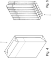
- the pack 1 for cigarettes comprises a cup-shaped outer container 2 made of cardboard or rigid paperboard and a wrap 3 (better illustrated in Figure 4 ) housed inside the container 2.
- the outer container 2 has an open upper end and is provided with a lid 4, which is cup-shaped and is hinged to the outer container 2 along a hinge (illustrated in Figure 2 ) so as to rotate, relative to the outer container 2, between an open position (illustrated in Figure 3 ) and a closed position (illustrated in Figures 1 and 2 ) of the open upper end.
- a hinge illustrated in Figure 2
- the wrap 3 encloses a group 5 of cigarettes (illustrated in Figure 5 ) with a parallelepiped shape and has, at the top and at the front, a removable portion which is separated from the rest of the wrap 3 by a pre-weakened tearable line.
- the pack 1 for cigarettes further comprises a rigid collar 6, which is connected (by means of gluing) folded in a "U" shape on the inside of the outer container 2 so as to partially project on the outside of the open upper end of the outer container 2 and engage a corresponding inner surface of the lid 4 when the lid 4 is arranged in the closed position.
- the wrap 3 is made by folding around the group 5 of cigarettes a wrapping sheet 7 provided, on a side, with the tearable line which delimits the removable portion.
- the final shape of the wrapping sheet 7 around the group 5 of cigarettes is not stabilized in any manner (i.e. no glue is applied to the wrapping sheet 7 and no seals are made on the wrapping sheet 7); consequently, the final shape of the wrapping sheet 7 around the group 5 of cigarettes is maintained only by effect of the containing action of the outer container 2.
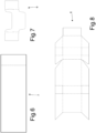
- the outer container 2 and the lid 4 are made by folding a blank 8 of conventional type.
- reference number 9 indicates, as a whole, a packer machine which is designed to manufacture the pack 1 for cigarettes described above and operates with an intermittent motion (i.e. a motion which provides for a cyclic alternation of motion phases and standstill phases).
- the packer machine 9 comprises a forming unit A, in which the groups 5 of cigarettes are formed in succession, a wrapping unit B, in which a respective wrapping sheet 7 is wrapped around each group 5 of cigarettes so as to produce a wrap 3, and a wrapping unit C, in which a collar 6 and a blank 8 are wrapped around each wrap 3 so as to produce an outer container 2 provided with lid 4.
- the forming unit A of the groups 5 of cigarettes comprises a hopper 10 provided with three output mouths for simultaneously supplying three groups 5 of cigarettes to three respective pockets 11 of a forming conveyor 12 which supports a plurality of pockets 11 and moves stepwise so as to cyclically move the pockets 11 along a forming path P1.
- the forming path P1 develops between an input station S 1, in which each group 5 of cigarettes is extracted from an output mouth of the hopper 10 and enters a corresponding pocket 11 of the forming conveyor 12, and a transfer station S2, in which each group 5 of cigarettes is extracted from the corresponding pocket 11 of the forming conveyor 12.
- the wrapping unit B comprises a wrapping conveyor 13 designed to move each group 5 of cigarettes along a straight and horizontal wrapping path P2.
- the wrapping path P2 extends from the transfer station S2, in which the wrapping conveyor 13 extracts each group 5 of cigarettes from the corresponding pocket 11 of the forming conveyor 12, passes through a supply station S3, in which each group 5 of cigarettes couples to a corresponding wrapping sheet 7 which folds in a "U" shape around the group 5 of cigarettes, and ends in a transfer station S4, in which each wrap 3 (formed by a wrapping sheet 7 at least partially folded around a group 5 of cigarettes) leaves the wrapping conveyor 13.
- each wrapping sheet 7 is arranged so as to be intercepted by a corresponding group 5 of cigarettes around which the wrapping sheet 7 folds in a "U"-shape; in other words, each group 5 of cigarettes moving along the wrapping path P2 intercepts a corresponding wrapping sheet 7 arranged in the supply station S3 determining the "U"-shape folding of the wrapping sheet 7.
- the packer machine 9 comprises a supply device 14, which cyclically supplies the wrapping sheets 7 into the supply station S3, i.e. arranges each wrapping sheet 7 in the supply station S3 in such a manner that the wrapping sheet 7 is intercepted by a corresponding group 5 of cigarettes moving along the wrapping path P2.
- the supply device 14 comprises an unwinding station, in which a band 15 of wrapping material is unwound from a reel 16 and is moved (passing next to the hopper 10) towards a cutting member 17 of known type which is arranged above the supply station S3 and cyclically performs a transversal cut of the band 15 of wrapping material so as to separate the individual wrapping sheets 7 from the band 15 of wrapping material.
- the wrapping unit B comprises a folding device 18 which is arranged along the wrapping path P2 at the wrapping conveyor 13 and is designed to fold two open side ends of each wrapping sheet 7 folded in a "U"-shape around a corresponding group 5 of cigarettes so as to form a tubular wrap having an open rear end.
- the folding device 18 only comprises folding profiles (i.e. folding spirals) which are fixed (i.e. totally without parts in movement) and are arranged on opposite sides of the wrapping path P2.
- the wrapping path P2 starts in the transfer station S2 (in which the groups 5 of cigarettes enter the wrapping conveyor 13) and ends in the transfer station S4 (in which the wraps 3 leave the wrapping conveyor 13).
- the packer machine comprises a transfer conveyor 19 which receives the wraps 3 in a transfer station S5 and moves the wraps 3 along a straight transfer path P3 perpendicular to the wrapping path P2.
- the transfer conveyor 19 comprises a conveyor belt with an annular shape, which is wrapped around two end pulleys (one of which is motorized), supports a plurality of pockets 20 each designed to house a corresponding wrap 3, and moves stepwise so as to cyclically move the pockets 20 along the transfer path P3.
- the wrapping unit B comprises a folding device 21 which is arranged downstream of the folding device 18 and is designed to complete a folding of each wrapping sheet 7 around the corresponding group 5 of cigarettes (and thus end the manufacturing of the wrap 3) so as to close the open rear end (i.e. previously left open by the folding device 18).
- a transport unit 22 is interposed which is configured to transfer the wraps 3 from the transfer station S4 (i.e. from the output of the wrapping conveyor 13) to the transfer station S5 (i.e. to the input of the transfer conveyor 19) along a prolongation of the wrapping path P2.
- the supply device 14 comprises two folding spindles 23 which are supported by a moving conveyor 24 which cyclically moves each folding spindle 23 between a receiving station S6, in which each wrapping sheet 7 is coupled to the folding spindle 23, and the supply station S3 at the wrapping path P2 and in which the wrapping sheet 7 is coupled to a group 5 of cigarettes which, moving along the wrapping path P2, intercepts the wrapping sheet 7 which folds in a "U"-shape around the group 5 of cigarettes.
- the transport unit 22 is configured to transport each wrap 3 along the wrapping path P2 (i.e. along a prolongation of the wrapping path P2) from the transfer station S4 (i.e. from the output of the wrapping conveyor 13) to the transfer station S5 (i.e. at the input of the transfer conveyor 19).
- the transport unit 22 comprises a drawer 25 provided with a frame 26 with a parallelepiped shape, in which is defined a pocket 27 with a parallelepiped shape configured to house a wrap 3.
- the pocket 27 has a tubular shape (i.e. is open at the two opposite ends) and thus has two openings opposite each other through which a wrap 3 enters (in the transfer station S4) the pocket 27 and subsequently exits (in the transfer station S5) the pocket 27.
- the pocket 27 is delimited by a base wall 28 which is integral with the frame 26 (i.e. in use does not make any type of movement with respect to the frame 26), by two side walls 29 which are integral with the frame 26 (i.e. in use do not make any type of movement with respect to the frame 26) and are arranged perpendicular to the base wall 28, and by a containing wall 30 which is parallel to and opposite the base wall 28 and is mounted in a movable manner on the frame 26 so as to move with respect to the frame 26 approaching the base wall 28 or moving away from the base wall 28.
- the containing wall 30 is movable with respect to the frame 26 so as to move along a holding direction DP (illustrated in Figures 15 , 16 and 17 ) which is perpendicular to the base wall 28 and to the containing wall 30 and is thus parallel to the side walls 29.
- a holding direction DP illustrated in Figures 15 , 16 and 17
- the base wall 28 of the pocket 27 centrally has a slit 31 passing through which a guide can be inserted which precedes a wrap 3 in the transfer station S4 (in which a wrap 3 enters the pocket 27) and/or a pusher which pushes a wrap 3 into the transfer station S5 (in which a wrap 3 exits the pocket 27).
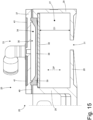
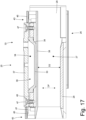
- the containing wall 30 is mounted in a movable manner on the frame 26 so as to move between a loading and unloading position (illustrated in Figure 15 ), in which it gives the pocket 27 a dimension D1 (measured along the holding direction DP) and a transport position (illustrated in Figures 16 and 17 ), in which it gives the pocket 27 a dimension D2 (measured along the holding direction DP) smaller than the dimension D 1.
- the pocket 27 is arranged in the loading and unloading position (illustrated in Figure 15 ) so as to facilitate the sliding of the wrap 3 with respect to the walls 28, 29 and 30 of the pocket 27 (i.e. to avoid that the wrap 3 is pressed against the walls 28, 29 and 30 of the pocket 27, thus increasing the friction against the walls 28, 29 and 30 of the pocket 27).
- the pocket 27 is arranged and maintained in the transport position (illustrated in Figures 16 and 17 ) so as to compress the wrap 3 housed in the pocket 27 and thus prevent, by effect of the accelerations and decelerations to which the pocket 27 is subject during the movement, the wrap 3 from deforming in an uncontrolled manner (the wrap 3 is without glue and thus tends to lose its shape if not suitably contained).
- the transport unit 22 comprises a conveyor device 32 which is configured to move the drawer 25 along the wrapping path P2.
- the wrapping path P2 is linear and thus the conveyor device 32 moves the drawer 25 forward and backward in straight line between the transfer stations S4 and S5; according to a different embodiment not illustrated, the wrapping path P2 could be circular and thus the conveyor device 32 (having a drum mounted in a rotatable manner) moves the drawer 25 along a circle which in succession passes through the transfer stations S4 and S5 (in this embodiment the conveyor device 32 could support a plurality of drawers 25).
- the transport unit 22 comprises an actuator device 33 which can be operated for pushing the containing wall 30 towards the transport position (illustrated in Figures 16 and 17 ).
- the actuator device 33 is pneumatic, i.e. utilizes the thrust generated by a fluid (for example air) under pressure.
- the actuator device 33 comprises an actuation chamber 34 which is arranged next to the containing wall 30, can be connected through a solenoid valve to a source 35 of fluid under pressure (for example compressed air), and is configured to press against the containing wall 30 when it is in overpressure conditions.
- the actuator device 33 comprises a flexible wall 36 which is elastically deformable, delimits the actuation chamber 34, is directly in contact with the containing wall 30 and swells pressing against the containing wall 30 when the actuation chamber 34 is in overpressure conditions.
- the actuator device 33 comprises an outer wall 37 which is rigid (i.e. does not deform in use), is integral with the frame 26 of the drawer 25 and defines the actuation chamber 34 together with the flexible wall 36; namely, the outer wall 37 is opposite the flexible wall 36 for enclosing the actuation chamber 34 together with the flexible wall 36.
- the outer wall 37 is substantially flat, whereas the flexible wall 36 is (centrally) cup-shaped for giving a certain volume to the actuation chamber 34.
- the flexible wall 36 comprises a central area 38 having a first thickness and a peripheral area 39 which is arranged around the central area 38 and has a second thickness greater than the first thickness. Both the central area 38, and the peripheral area 39 of the flexible wall 36 are free (i.e. are not engaged at the top and at the bottom by rigid elements) and thus, in use, can freely deform.
- the flexible wall 36 has an edge 40 which has a third thickness smaller than the first thickness and the second thickness and is constrained to the frame 26 of the pocket 27; namely, the edge 40 of the flexible wall 36 is compressed (for creating a pneumatic sealing) between two elements of the frame 26 of the drawer 25 and in particular is compressed between the outer wall 37 and the two side walls 29.
- the central area 38 of the flexible wall 36 is flat, is coplanar to the containing wall 30 and is directly in contact with the containing wall 30, whereas the peripheral area 39 of the flexible wall 36 is curved and causes the flexible wall 36 to be cup-shaped.
- the drawer 25 is coupled to two elastic elements 41 (in particular two flat springs) which push the containing wall 30 towards the loading and unloading position (illustrated in Figure 15 ) and elastically deform when the actuator device 33 moves the containing wall 30 towards the transport position (illustrated in Figures 16 and 17 ).
- the two elastic elements 41 are arranged next to each other, are arranged in respective seats 42 which are obtained in an outer surface (i.e.
- each elastic element 41 centrally has a swelling (obviously present also in the respective seat 42) which determines a precise positioning of the elastic element 41 in the respective seat 42 preventing a longitudinal sliding of the elastic element 41 along the respective seat 42.
- the containing wall 30 longitudinally comes out on both sides of the actuation chamber 34 (i.e. both of the flexible wall 36, and of the outer wall 37) and has, at the two ends, two annular bodies 43 inside which the elastic elements 41 are inserted for elastically pushing the containing wall 30 towards the loading and unloading position (illustrated in Figure 15 ).
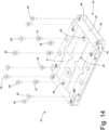
- Each annular body 43 consists, on one side, of the containing wall 30 from which two columns 44 rise perpendicularly and, on the other side, of a plate 45 (against which the ends of the elastic elements 41 rest) which is fixed to the columns 44 of the containing wall 30 by means of two screws 46 (better illustrated in Figure 14 ).
- the drawer 25 comprises two striker bodies 47 against which the containing wall 30 rests in the loading and unloading position (illustrated in Figure 15 ); namely, the striker bodies 47 constitute end stops which establish the loading and unloading position (illustrated in Figure 15 ).
- each striker body 47 is a screw which is screwed into a threaded hole 48 obtained through the outer wall 37 of the frame 26 (externally the actuation chamber 34) and can be screwed or unscrewed in order to change the loading and unloading position (illustrated in Figure 15 ), i.e.
- screws 49 are provided (obviously the number of the screws 49 could be different), each of which is arranged through a through hole obtained in the outer wall 37 and screws into a threaded dead hole obtained through a side wall 29 of the pocket 27; in this manner, the screws 49 firmly connect the outer wall 37 to the side walls 29 of the pocket 27 with the interposition of the edge 40 of the flexible wall 37.
- all of the pneumatic actuator device 33 is replaced by an (at least one) elastic element which pushes the containing wall 30 towards the transport position (illustrated in Figures 16 and 17 ) and which is elastically compressed by the thrust applied by a wrap 3 when the wrap 3 enters the pocket 27.
- the movement of the containing wall 30 is completely passive, i.e. is determined by the presence of a wrap 3 in the pocket 27.
- This alternative embodiment generates greater stresses on a wrap 3 when the wrap 3 enters the pocket 27 since it is the wrap 3 that has to push on the containing wall 30 for moving the containing wall 30 towards the loading and unloading position (illustrated in Figure 15 ) and thus create the space necessary for its entering the pocket 27; on the other hand, this alternative embodiment is constructively simpler replacing all of the pneumatic actuator device 33 with an (at least one) elastic element.
- the compression which is applied to a wrap 3 which is inside the pocket 27 is determined by the pneumatic thrust exerted by the containing wall 30 on the wrap 3 and thus depends on the pressure of the fluid which is supplied inside the compression chamber 34; in this manner, the compression which is applied to each wrap 3 is always constant independently of the actual dimension of the wrap 3 (i.e. independently of the fact that the wrap 3 can be a little thicker or a little less thicker due to the inevitable constructive tolerances) and the compression which is applied to each wrap 3 is easily adjustable by changing the pressure of the fluid which is supplied inside the compression chamber 34.
- the transport unit 22 is utilized for moving wraps 3 each containing a group 5 of cigarettes; according to other embodiments not illustrated, the transport unit 22 can be utilized for moving other types of products both of the industry for working smoking articles, and of other industries (for example food products, pharmaceutical products, cosmetic products).
- the embodiment illustrated in the accompanying figures refers to the manufacturing of a pack for cigarettes, but the present invention is applicable without substantial modifications also to the manufacturing of any other type of pack for smoking articles (for example a pack for cigars, a pack for electronic cigarettes of the liquid vaporization type, a pack for cigarettes of new generation without tobacco combustion ).
- the transport unit 22 described above has numerous advantages.
- the transport unit 22 described above allows transporting in a safe manner the products (in particular the wraps 3) also operating at a high production speed.
- the transport unit 22 described above is capable of transporting the products (in particular the wraps 3) without damaging the products due to an excessive compression of the products and, simultaneously, without leaving the products excessively free so as to prevent an undesired uncontrolled deformation of the products (the wraps 3 are not provided with glue and thus tend to lose their shape if not suitably contained).
- the transport unit 22 described above is simple to manufacture since the drawer 25 is composed of a limited number of components which can be found in commerce or which are easy to construct.
Landscapes
- Engineering & Computer Science (AREA)
- Mechanical Engineering (AREA)
- Wrapping Of Specific Fragile Articles (AREA)
Abstract
Description
- This patent application claims priority from
Italian patent application no. 102023000008607 filed on May 2, 2023 - The present invention relates to a packer machine to produce a rigid pack for smoking articles.
- The present invention can be applied advantageously to the manufacturing of a wrap of a rigid pack for cigarettes with a hinged lid by folding a wrapping sheet of metallized paper around a group of cigarettes, to which the following discussion will make explicit reference without any loss of generality.
- Rigid packs for cigarettes with a hinged lid currently are the most widespread packs for cigarettes on the market since they are simple to manufacture, are easy and practical to use, and offer a good protection to the cigarettes contained therein.
- A rigid pack for cigarettes with a hinged lid comprises a wrap consisting of a group of cigarettes wrapped in a sheet of metallized paper and a rigid outer shell which houses the wrap therein. The outer shell consists of a cup-shaped container, which houses the group of cigarettes and has an open upper end, and a lid, which is also cup-shaped and is hinged to the container so as to rotate, relative to the container, between an open position and a closed position of the open end.
- Patent application
EP3725691A1 describes a packer machine for producing a rigid pack for cigarettes having: a wrap formed by folding a wrapping sheet of metallized paper around a group of cigarettes, and an outer container formed by folding a blank and a collar around the wrap. The following is provided: a forming conveyor, which moves a plurality of first pockets along a forming path; a hopper, which is arranged in front of the forming conveyor and along the forming path and is provided with at least one output mouth, from which the group of cigarettes can be extracted; a wrapping conveyor, which is arranged downstream of the forming conveyor and is designed to move the group of cigarettes and the wrapping sheet along a first straight and horizontal wrapping path; a first wrapping wheel, which is arranged downstream of the wrapping conveyor, supports at least a second pocket designed to contain the wrap and the collar, and is mounted in a rotatable manner around a first horizontal rotation axis parallel to the first wrapping path so as to move the second pocket along a second circular wrapping path; a second wrapping wheel, which is arranged downstream of the first wrapping wheel, supports at least a third pocket designed to contain the wrap, the collar and the blank, and is mounted in a rotatable manner around a second horizontal rotation axis parallel to the first rotation axis so as to move the third pocket along a third circular wrapping path; and a transfer conveyor, which is interposed between the wrapping conveyor and the first wrapping wheel and transfers the wrap from the wrapping conveyor to the first wrapping wheel along a transfer path perpendicular to the first wrapping path and perpendicular to the first rotation axis. - In the packer machine described above it is necessary to transport the wraps being formed from the wrapping conveyor to the transfer conveyor without damaging the wraps due to an excessive compression of the wraps and, simultaneously, without leaving the wraps excessively free so as to avoid an undesired uncontrolled deformation of the wraps (which are not provided with glue and thus tend to lose their shape if not suitably contained). Patent
US3608701A1 describes an adjustable transport drawer for the products of a packer machine; the drawer is equipped with a dividing element mounted in a sliding manner on the lower wall of the drawer. - The object of the present invention is to provide a packer machine for producing a rigid pack for smoking articles which allows transporting in a safe manner a product, in particular a wrap consisting of a group of smoking articles wrapped in a wrapping sheet of metallized paper, also operating at a high production speed.
- In accordance with the present invention, a packer machine for producing a rigid pack for smoking articles is provided, as claimed in the appended claims.
- The claims describe embodiments of the present invention and constitute an integral part of the present description.
- The present invention will now be described with reference to the accompanying drawings, which illustrate a non-limiting example embodiment thereof, wherein:
-
Figure 1 is a front perspective view, in a closed configuration, of a rigid pack for cigarettes; -
Figure 2 is a rear perspective view of the pack for cigarettes ofFigure 1 , in a closed configuration; -
Figure 3 is a front perspective view of the pack for cigarettes ofFigure 1 , in an open configuration; -
Figure 4 is a front perspective view of a wrap of the pack ofFigure 1 ; -
Figure 5 is a perspective view of a group of cigarettes contained in the wrap ofFigure 4 ; -
Figure 6 is a plan view of a wrapping sheet utilized for manufacturing the wrap ofFigure 4 ; -
Figure 7 is a plan view of a collar of the pack for cigarettes ofFigure 1 ; -
Figure 8 is a plan view of a blank utilized for manufacturing an outer container provided with a hinged lid of the pack for cigarettes ofFigure 1 ; -
Figure 9 is a schematic perspective view, with parts removed for clarity, of a packer machine which produces the pack for cigarettes ofFigure 1 and is manufactured in accordance with the present invention; -
Figure 10 is a schematic perspective view, with parts removed, of a part of the packer machine ofFigure 9 ; -
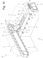
Figures 11 and12 are two different perspective views, with parts removed for clarity, of a drawer of transport units of the packer machine ofFigure 9 ; -
Figure 13 is an exploded perspective view, with parts removed for clarity, of part of the drawer ofFigures 11 and12 ; -
Figure 14 is a perspective view, with in evidence screws, of part of the drawer ofFigures 11 and12 ; -
Figures 15 and16 are two cross-section views of the drawer ofFigures 11 and12 , in two different operating conditions; and -
Figure 17 is a longitudinal section view of the drawer ofFigures 11 and12 . - In
Figures 1, 2 and3 ,reference number 1 indicates, as a whole, a rigid pack for cigarettes. Thepack 1 for cigarettes comprises a cup-shapedouter container 2 made of cardboard or rigid paperboard and a wrap 3 (better illustrated inFigure 4 ) housed inside thecontainer 2. - The
outer container 2 has an open upper end and is provided with alid 4, which is cup-shaped and is hinged to theouter container 2 along a hinge (illustrated inFigure 2 ) so as to rotate, relative to theouter container 2, between an open position (illustrated inFigure 3 ) and a closed position (illustrated inFigures 1 and 2 ) of the open upper end. - The
wrap 3 encloses agroup 5 of cigarettes (illustrated inFigure 5 ) with a parallelepiped shape and has, at the top and at the front, a removable portion which is separated from the rest of thewrap 3 by a pre-weakened tearable line. - According to what is illustrated in
Figures 3 and7 , thepack 1 for cigarettes further comprises arigid collar 6, which is connected (by means of gluing) folded in a "U" shape on the inside of theouter container 2 so as to partially project on the outside of the open upper end of theouter container 2 and engage a corresponding inner surface of thelid 4 when thelid 4 is arranged in the closed position. - According to what is illustrated in
Figure 6 , thewrap 3 is made by folding around thegroup 5 of cigarettes awrapping sheet 7 provided, on a side, with the tearable line which delimits the removable portion. - According to a preferred embodiment, the final shape of the
wrapping sheet 7 around thegroup 5 of cigarettes is not stabilized in any manner (i.e. no glue is applied to thewrapping sheet 7 and no seals are made on the wrapping sheet 7); consequently, the final shape of thewrapping sheet 7 around thegroup 5 of cigarettes is maintained only by effect of the containing action of theouter container 2. - According to what is illustrated in
Figure 8 , theouter container 2 and thelid 4 are made by folding a blank 8 of conventional type. - In
Figure 9 ,reference number 9 indicates, as a whole, a packer machine which is designed to manufacture thepack 1 for cigarettes described above and operates with an intermittent motion (i.e. a motion which provides for a cyclic alternation of motion phases and standstill phases). - The
packer machine 9 comprises a forming unit A, in which thegroups 5 of cigarettes are formed in succession, a wrapping unit B, in which arespective wrapping sheet 7 is wrapped around eachgroup 5 of cigarettes so as to produce awrap 3, and a wrapping unit C, in which acollar 6 and a blank 8 are wrapped around eachwrap 3 so as to produce anouter container 2 provided withlid 4. - The forming unit A of the
groups 5 of cigarettes comprises ahopper 10 provided with three output mouths for simultaneously supplying threegroups 5 of cigarettes to threerespective pockets 11 of a formingconveyor 12 which supports a plurality ofpockets 11 and moves stepwise so as to cyclically move thepockets 11 along a forming path P1. The forming path P1 develops between aninput station S 1, in which eachgroup 5 of cigarettes is extracted from an output mouth of thehopper 10 and enters acorresponding pocket 11 of the formingconveyor 12, and a transfer station S2, in which eachgroup 5 of cigarettes is extracted from thecorresponding pocket 11 of the formingconveyor 12. - The wrapping unit B comprises a wrapping
conveyor 13 designed to move eachgroup 5 of cigarettes along a straight and horizontal wrapping path P2. In particular, the wrapping path P2 extends from the transfer station S2, in which the wrappingconveyor 13 extracts eachgroup 5 of cigarettes from thecorresponding pocket 11 of the formingconveyor 12, passes through a supply station S3, in which eachgroup 5 of cigarettes couples to acorresponding wrapping sheet 7 which folds in a "U" shape around thegroup 5 of cigarettes, and ends in a transfer station S4, in which each wrap 3 (formed by awrapping sheet 7 at least partially folded around agroup 5 of cigarettes) leaves the wrappingconveyor 13. - Along the wrapping path P2 (at the wrapping conveyor 13) a supply station S3 is present, in which each
wrapping sheet 7 is arranged so as to be intercepted by acorresponding group 5 of cigarettes around which thewrapping sheet 7 folds in a "U"-shape; in other words, eachgroup 5 of cigarettes moving along the wrapping path P2 intercepts acorresponding wrapping sheet 7 arranged in the supply station S3 determining the "U"-shape folding of thewrapping sheet 7. - The
packer machine 9 comprises asupply device 14, which cyclically supplies thewrapping sheets 7 into the supply station S3, i.e. arranges eachwrapping sheet 7 in the supply station S3 in such a manner that thewrapping sheet 7 is intercepted by acorresponding group 5 of cigarettes moving along the wrapping path P2. According to what is illustrated inFigure 9 , thesupply device 14 comprises an unwinding station, in which aband 15 of wrapping material is unwound from areel 16 and is moved (passing next to the hopper 10) towards acutting member 17 of known type which is arranged above the supply station S3 and cyclically performs a transversal cut of theband 15 of wrapping material so as to separate theindividual wrapping sheets 7 from theband 15 of wrapping material. - According to what is illustrated in
Figure 10 , the wrapping unit B comprises afolding device 18 which is arranged along the wrapping path P2 at thewrapping conveyor 13 and is designed to fold two open side ends of eachwrapping sheet 7 folded in a "U"-shape around acorresponding group 5 of cigarettes so as to form a tubular wrap having an open rear end. Preferably, thefolding device 18 only comprises folding profiles (i.e. folding spirals) which are fixed (i.e. totally without parts in movement) and are arranged on opposite sides of the wrapping path P2. - The wrapping path P2 starts in the transfer station S2 (in which the
groups 5 of cigarettes enter the wrapping conveyor 13) and ends in the transfer station S4 (in which thewraps 3 leave the wrapping conveyor 13). According to what is illustrated inFigure 10 , the packer machine comprises atransfer conveyor 19 which receives thewraps 3 in a transfer station S5 and moves thewraps 3 along a straight transfer path P3 perpendicular to the wrapping path P2. Thetransfer conveyor 19 comprises a conveyor belt with an annular shape, which is wrapped around two end pulleys (one of which is motorized), supports a plurality ofpockets 20 each designed to house acorresponding wrap 3, and moves stepwise so as to cyclically move thepockets 20 along the transfer path P3. - According to what is illustrated in
Figure 10 , the wrapping unit B comprises afolding device 21 which is arranged downstream of thefolding device 18 and is designed to complete a folding of eachwrapping sheet 7 around thecorresponding group 5 of cigarettes (and thus end the manufacturing of the wrap 3) so as to close the open rear end (i.e. previously left open by the folding device 18). - Between the wrapping
conveyor 13 and thetransfer conveyor 19, atransport unit 22 is interposed which is configured to transfer thewraps 3 from the transfer station S4 (i.e. from the output of the wrapping conveyor 13) to the transfer station S5 (i.e. to the input of the transfer conveyor 19) along a prolongation of the wrapping path P2. - According to what is illustrated in
Figure 10 , thesupply device 14 comprises twofolding spindles 23 which are supported by a movingconveyor 24 which cyclically moves eachfolding spindle 23 between a receiving station S6, in which eachwrapping sheet 7 is coupled to thefolding spindle 23, and the supply station S3 at the wrapping path P2 and in which thewrapping sheet 7 is coupled to agroup 5 of cigarettes which, moving along the wrapping path P2, intercepts thewrapping sheet 7 which folds in a "U"-shape around thegroup 5 of cigarettes. - For further details on the
packer machine 9, reference is made to what is described in patent applicationEP3725691A1 . - As mentioned in the foregoing, the
transport unit 22 is configured to transport eachwrap 3 along the wrapping path P2 (i.e. along a prolongation of the wrapping path P2) from the transfer station S4 (i.e. from the output of the wrapping conveyor 13) to the transfer station S5 (i.e. at the input of the transfer conveyor 19). According to what is illustrated inFigures 11 and12 , thetransport unit 22 comprises adrawer 25 provided with aframe 26 with a parallelepiped shape, in which is defined apocket 27 with a parallelepiped shape configured to house awrap 3. In particular, thepocket 27 has a tubular shape (i.e. is open at the two opposite ends) and thus has two openings opposite each other through which awrap 3 enters (in the transfer station S4) thepocket 27 and subsequently exits (in the transfer station S5) thepocket 27. - The
pocket 27 is delimited by abase wall 28 which is integral with the frame 26 (i.e. in use does not make any type of movement with respect to the frame 26), by twoside walls 29 which are integral with the frame 26 (i.e. in use do not make any type of movement with respect to the frame 26) and are arranged perpendicular to thebase wall 28, and by a containingwall 30 which is parallel to and opposite thebase wall 28 and is mounted in a movable manner on theframe 26 so as to move with respect to theframe 26 approaching thebase wall 28 or moving away from thebase wall 28. Namely, the containingwall 30 is movable with respect to theframe 26 so as to move along a holding direction DP (illustrated inFigures 15 ,16 and17 ) which is perpendicular to thebase wall 28 and to the containingwall 30 and is thus parallel to theside walls 29. - According to a preferred embodiment, the
base wall 28 of thepocket 27 centrally has aslit 31 passing through which a guide can be inserted which precedes awrap 3 in the transfer station S4 (in which awrap 3 enters the pocket 27) and/or a pusher which pushes awrap 3 into the transfer station S5 (in which awrap 3 exits the pocket 27). - The containing
wall 30 is mounted in a movable manner on theframe 26 so as to move between a loading and unloading position (illustrated inFigure 15 ), in which it gives the pocket 27 a dimension D1 (measured along the holding direction DP) and a transport position (illustrated inFigures 16 and17 ), in which it gives the pocket 27 a dimension D2 (measured along the holding direction DP) smaller than thedimension D 1. - All of the
walls wrap 3 when thewrap 3 enters the transfer station S4 in thepocket 27. In the transfer station S4 (in which awrap 3 enters the pocket 27) and in the transfer station S5 (in which awrap 3 exits the pocket 27) thepocket 27 is arranged in the loading and unloading position (illustrated inFigure 15 ) so as to facilitate the sliding of thewrap 3 with respect to thewalls wrap 3 is pressed against thewalls pocket 27, thus increasing the friction against thewalls wrap 3 enters the pocket 27) and the transfer station S5 (in which awrap 3 exits the pocket 27), i.e. during the movement of thepocket 27 along the wrapping path P2, thepocket 27 is arranged and maintained in the transport position (illustrated inFigures 16 and17 ) so as to compress thewrap 3 housed in thepocket 27 and thus prevent, by effect of the accelerations and decelerations to which thepocket 27 is subject during the movement, thewrap 3 from deforming in an uncontrolled manner (thewrap 3 is without glue and thus tends to lose its shape if not suitably contained). - According to what is illustrated in
Figures 11 and12 , thetransport unit 22 comprises aconveyor device 32 which is configured to move thedrawer 25 along the wrapping path P2. In the embodiment illustrated in the accompanying figures, the wrapping path P2 is linear and thus theconveyor device 32 moves thedrawer 25 forward and backward in straight line between the transfer stations S4 and S5; according to a different embodiment not illustrated, the wrapping path P2 could be circular and thus the conveyor device 32 (having a drum mounted in a rotatable manner) moves thedrawer 25 along a circle which in succession passes through the transfer stations S4 and S5 (in this embodiment theconveyor device 32 could support a plurality of drawers 25). - According to what is illustrated in
Figures 15 ,16 and17 , thetransport unit 22 comprises anactuator device 33 which can be operated for pushing the containingwall 30 towards the transport position (illustrated inFigures 16 and17 ). Preferably, theactuator device 33 is pneumatic, i.e. utilizes the thrust generated by a fluid (for example air) under pressure. According to what is illustrated inFigures 15 ,16 and17 , theactuator device 33 comprises anactuation chamber 34 which is arranged next to the containingwall 30, can be connected through a solenoid valve to asource 35 of fluid under pressure (for example compressed air), and is configured to press against the containingwall 30 when it is in overpressure conditions. In particular, theactuator device 33 comprises aflexible wall 36 which is elastically deformable, delimits theactuation chamber 34, is directly in contact with the containingwall 30 and swells pressing against the containingwall 30 when theactuation chamber 34 is in overpressure conditions. Theactuator device 33 comprises anouter wall 37 which is rigid (i.e. does not deform in use), is integral with theframe 26 of thedrawer 25 and defines theactuation chamber 34 together with theflexible wall 36; namely, theouter wall 37 is opposite theflexible wall 36 for enclosing theactuation chamber 34 together with theflexible wall 36. Preferably, theouter wall 37 is substantially flat, whereas theflexible wall 36 is (centrally) cup-shaped for giving a certain volume to theactuation chamber 34. - According to a preferred embodiment better illustrated in
Figure 13 , theflexible wall 36 comprises acentral area 38 having a first thickness and aperipheral area 39 which is arranged around thecentral area 38 and has a second thickness greater than the first thickness. Both thecentral area 38, and theperipheral area 39 of theflexible wall 36 are free (i.e. are not engaged at the top and at the bottom by rigid elements) and thus, in use, can freely deform. Around theperipheral area 39, theflexible wall 36 has anedge 40 which has a third thickness smaller than the first thickness and the second thickness and is constrained to theframe 26 of thepocket 27; namely, theedge 40 of theflexible wall 36 is compressed (for creating a pneumatic sealing) between two elements of theframe 26 of thedrawer 25 and in particular is compressed between theouter wall 37 and the twoside walls 29. - According to a preferred embodiment better illustrated in
Figures 15 ,16 and17 , thecentral area 38 of theflexible wall 36 is flat, is coplanar to the containingwall 30 and is directly in contact with the containingwall 30, whereas theperipheral area 39 of theflexible wall 36 is curved and causes theflexible wall 36 to be cup-shaped. - According to what is better illustrated in
Figures 13 and14 , thedrawer 25 is coupled to two elastic elements 41 (in particular two flat springs) which push the containingwall 30 towards the loading and unloading position (illustrated inFigure 15 ) and elastically deform when theactuator device 33 moves the containingwall 30 towards the transport position (illustrated inFigures 16 and17 ). In particular, the twoelastic elements 41 are arranged next to each other, are arranged inrespective seats 42 which are obtained in an outer surface (i.e. opposite the actuation chamber 34) of theouter wall 37 and reproduce in negative the shape of theelastic elements 41; according to a preferred embodiment illustrated in the accompanying figures, eachelastic element 41 centrally has a swelling (obviously present also in the respective seat 42) which determines a precise positioning of theelastic element 41 in therespective seat 42 preventing a longitudinal sliding of theelastic element 41 along therespective seat 42. - The containing
wall 30 longitudinally comes out on both sides of the actuation chamber 34 (i.e. both of theflexible wall 36, and of the outer wall 37) and has, at the two ends, twoannular bodies 43 inside which theelastic elements 41 are inserted for elastically pushing the containingwall 30 towards the loading and unloading position (illustrated inFigure 15 ). Eachannular body 43 consists, on one side, of the containingwall 30 from which twocolumns 44 rise perpendicularly and, on the other side, of a plate 45 (against which the ends of theelastic elements 41 rest) which is fixed to thecolumns 44 of the containingwall 30 by means of two screws 46 (better illustrated inFigure 14 ). - According to what is better illustrated in
Figure 13 , thedrawer 25 comprises twostriker bodies 47 against which the containingwall 30 rests in the loading and unloading position (illustrated inFigure 15 ); namely, thestriker bodies 47 constitute end stops which establish the loading and unloading position (illustrated inFigure 15 ). In particular, eachstriker body 47 is a screw which is screwed into a threadedhole 48 obtained through theouter wall 37 of the frame 26 (externally the actuation chamber 34) and can be screwed or unscrewed in order to change the loading and unloading position (illustrated inFigure 15 ), i.e. in order to change the dimension D1 assumed by thepocket 27 when the containingwall 30 is in the loading and unloading position (illustrated inFigure 15 ). According to what is illustrated inFigure 14 , also eightscrews 49 are provided (obviously the number of thescrews 49 could be different), each of which is arranged through a through hole obtained in theouter wall 37 and screws into a threaded dead hole obtained through aside wall 29 of thepocket 27; in this manner, thescrews 49 firmly connect theouter wall 37 to theside walls 29 of thepocket 27 with the interposition of theedge 40 of theflexible wall 37. - According to a different embodiment not illustrated, all of the
pneumatic actuator device 33 is replaced by an (at least one) elastic element which pushes the containingwall 30 towards the transport position (illustrated inFigures 16 and17 ) and which is elastically compressed by the thrust applied by awrap 3 when thewrap 3 enters thepocket 27. Namely, in this alternative embodiment, the movement of the containingwall 30 is completely passive, i.e. is determined by the presence of awrap 3 in thepocket 27. This alternative embodiment generates greater stresses on awrap 3 when thewrap 3 enters thepocket 27 since it is thewrap 3 that has to push on the containingwall 30 for moving the containingwall 30 towards the loading and unloading position (illustrated inFigure 15 ) and thus create the space necessary for its entering thepocket 27; on the other hand, this alternative embodiment is constructively simpler replacing all of thepneumatic actuator device 33 with an (at least one) elastic element. - It is important to observe that the compression which is applied to a
wrap 3 which is inside thepocket 27 is determined by the pneumatic thrust exerted by the containingwall 30 on thewrap 3 and thus depends on the pressure of the fluid which is supplied inside thecompression chamber 34; in this manner, the compression which is applied to eachwrap 3 is always constant independently of the actual dimension of the wrap 3 (i.e. independently of the fact that thewrap 3 can be a little thicker or a little less thicker due to the inevitable constructive tolerances) and the compression which is applied to eachwrap 3 is easily adjustable by changing the pressure of the fluid which is supplied inside thecompression chamber 34. - In the embodiment described above, the
transport unit 22 is utilized for movingwraps 3 each containing agroup 5 of cigarettes; according to other embodiments not illustrated, thetransport unit 22 can be utilized for moving other types of products both of the industry for working smoking articles, and of other industries (for example food products, pharmaceutical products, cosmetic products). In particular, the embodiment illustrated in the accompanying figures refers to the manufacturing of a pack for cigarettes, but the present invention is applicable without substantial modifications also to the manufacturing of any other type of pack for smoking articles (for example a pack for cigars, a pack for electronic cigarettes of the liquid vaporization type, a pack for cigarettes of new generation without tobacco combustion ...). - The embodiments described herein can be combined with one another without departing from the scope of protection of the present invention.
- The
transport unit 22 described above has numerous advantages. - Firstly, the
transport unit 22 described above allows transporting in a safe manner the products (in particular the wraps 3) also operating at a high production speed. Namely, thetransport unit 22 described above is capable of transporting the products (in particular the wraps 3) without damaging the products due to an excessive compression of the products and, simultaneously, without leaving the products excessively free so as to prevent an undesired uncontrolled deformation of the products (thewraps 3 are not provided with glue and thus tend to lose their shape if not suitably contained). Furthermore, thetransport unit 22 described above is simple to manufacture since thedrawer 25 is composed of a limited number of components which can be found in commerce or which are easy to construct. -
- 1
- pack for cigarettes
- 2
- outer container
- 3
- wrap
- 4
- lid
- 5
- group of cigarettes
- 6
- collar
- 7
- wrapping sheet
- 8
- blank
- 9
- packer machine
- 10
- hopper
- 11
- pockets
- 12
- forming conveyor
- 13
- wrapping conveyor
- 14
- supply device
- 15
- band
- 16
- reel
- 17
- cutting member
- 18
- folding device
- 19
- transfer conveyor
- 20
- pockets
- 21
- folding device
- 22
- transport unit
- 23
- folding spindle
- 24
- moving conveyor
- 25
- drawer
- 26
- frame
- 27
- 28
- base wall
- 29
- side walls
- 30
- containing wall
- 31
- slit
- 32
- conveyor device
- 33
- actuator device
- 34
- actuation chamber
- 35
- source of fluid under pressure
- 36
- flexible wall
- 37
- outer wall
- 38
- central area
- 39
- peripheral area
- 40
- edge
- 41
- elastic element
- 42
- seats
- 43
- annular bodies
- 44
- columns
- 45
- plate
- 46
- screws
- 47
- striker body
- 48
- threaded hole
- 49
- screws
- P1
- forming path
- P2
- wrapping path
- P3
- transfer path
- S1
- input station
- S2
- transfer station
- S3
- supply station
- S4
- transfer station
- S5
- transfer station
- S6
- receiving station
- A
- forming unit
- B
- wrapping unit
- C
- wrapping unit
- DP
- holding direction
- D1
- dimension
- D2
- dimension
Claims (11)
- A packer machine (9) to produce a rigid pack (1) for smoking articles comprising: a wrap (3) formed by folding a wrapping sheet (7) around a group (5) of smoking articles, and an outer container (2) formed by folding a blank (8) around the wrap (3); the packer machine (9) comprises:a forming conveyor (12), which moves a plurality of first pockets (11) along a forming path (P1);a hopper (10), which is arranged in front of the forming conveyor (12) and along the forming path (P1) and is provided with at least one output mouth, from which the group (5) of smoking articles can be extracted;a wrapping conveyor (13), which is arranged downstream of the forming conveyor (12) and is designed to move the group (5) of smoking articles and the wrapping sheet (7) along a straight wrapping path (P2) so as to fold the wrapping sheet (7) around the group (5) of smoking articles and, hence, form the wrap (3);a transfer conveyor (19), which receives the wrap (3) from the wrapping conveyor (13) and moves along a transfer path (P3), which is perpendicular to the wrapping path (P2); anda transport unit (22), which is interposed between the wrapping conveyor (13) and the transfer conveyor (19) and is configured to receive the wrap (3) from the wrapping conveyor (13) and release the wrap (3) in the transfer conveyor (19);wherein the transport unit (22) comprises: a drawer (25) provided with a frame (26), in which is defined a pocket (27) configured to house the product (3) and delimited, on a side, by a containing wall (30), which, in use, comes into contact with the product (3); and a conveyor device (32) configured to move the drawer (25) along the wrapping path (P2);the packer machine (9) is characterized in that the containing wall (30) is mounted on the frame (26) in a movable manner so as to move between a loading and unloading position, in which it gives the pocket (27) a first dimension (D1), and a transport position, in which it gives the pocket (27) a second dimension (D2) smaller than the first dimension (D1).
- The packer machine (9) according to claim 1 and comprising an actuator device (33), which can be operated so as to push the containing wall (30) towards the transport position.
- The packer machine (9) according to claim 2, wherein the actuator device (33) is pneumatic.
- The packer machine (9) according to claim 3, wherein the actuator device (33) comprises an actuation chamber (34), which is arranged next to the containing wall (30), can be connected to a source (35) of fluid under pressure and is configured to press against the containing wall (30) when it is in overpressure conditions.
- The packer machine (9) according to claim 4, wherein the actuator device (33) comprises a flexible wall (36), which is elastically deformable, delimits the actuation chamber (34), is directly in contact with the containing wall (30) and swells pressing against the containing wall (30) when the actuation chamber (34) is in overpressure conditions.
- The packer machine (9) according to claim 5, wherein the flexible wall (36) comprises a central area (38) having a first thickness and a peripheral area (39), which is arranged around the central area (38) and has a second thickness, which is greater than the first thickness.
- The packer machine (9) according to claim 6, wherein the central area (38) is flat, is coplanar to the containing wall (30) and is directly in contact with the containing wall (30), whereas the peripheral area (39) is curved and causes the flexible wall (36) to be cup-shaped.
- The packer machine (9) according to one of the claims from 2 to 7 and comprising at least one first elastic element (41), which pushes the containing wall (30) towards the loading and unloading position and elastically deforms when the actuator device (33) moves the containing wall (30) towards the transport position.
- The packer machine (9) according to one of the claims from 1 to 8 and comprising at least one first striker body (47), against which the containing wall (30) rests in the loading and unloading position.
- The packer machine (9) according to claim 9, wherein the first striker body (47) is screwed into a threaded hole (48) of the frame (26) and can be screwed or unscrewed in order to change the first dimension (D1) assumed by the pocket (27) when the containing wall (30) is in the loading and unloading position.
- The packer machine (9) according to claim 1 and comprising at least one second elastic element, which pushes the containing wall (30) towards the transport position.
Applications Claiming Priority (1)
| Application Number | Priority Date | Filing Date | Title |
|---|---|---|---|
| IT102023000008607A IT202300008607A1 (en) | 2023-05-02 | 2023-05-02 | UNIT AND METHOD OF TRANSPORT |
Publications (2)
| Publication Number | Publication Date |
|---|---|
| EP4458696A1 true EP4458696A1 (en) | 2024-11-06 |
| EP4458696B1 EP4458696B1 (en) | 2025-11-19 |
Family
ID=87136659
Family Applications (1)
| Application Number | Title | Priority Date | Filing Date |
|---|---|---|---|
| EP24172922.7A Active EP4458696B1 (en) | 2023-05-02 | 2024-04-29 | Packer machine to produce a rigid pack for smoking articles |
Country Status (3)
| Country | Link |
|---|---|
| EP (1) | EP4458696B1 (en) |
| IT (1) | IT202300008607A1 (en) |
| PL (1) | PL4458696T3 (en) |
Cited By (2)
| Publication number | Priority date | Publication date | Assignee | Title |
|---|---|---|---|---|
| EP4686660A2 (en) | 2024-07-29 | 2026-02-04 | G.D S.p.A. | Packer machine for producing a wrap by folding a wrapping sheet around a group of smoking articles |
| EP4686659A2 (en) | 2024-07-29 | 2026-02-04 | G.D S.p.A. | Packer machine for producing a wrap by folding a wrapping sheet around a group of smoking articles |
Families Citing this family (1)
| Publication number | Priority date | Publication date | Assignee | Title |
|---|---|---|---|---|
| IT202300008607A1 (en) | 2023-05-02 | 2024-11-02 | Gd Spa | UNIT AND METHOD OF TRANSPORT |
Citations (13)
| Publication number | Priority date | Publication date | Assignee | Title |
|---|---|---|---|---|
| DE1506515A1 (en) * | 1967-04-19 | 1970-01-22 | Fraunhofer Ges Forschung | Control device for pneumatically driven gripping tools movable gripper, preferably for inserting light or sensitive transport goods in packaging |
| CH491028A (en) | 1969-06-28 | 1970-05-31 | Fraunhofer Ges Forschung | Gripping device on a conveyor belt, preferably for placing sensitive goods in packaging |
| US3608701A (en) | 1969-06-03 | 1971-09-28 | Jones & Co Inc R A | Product bucket for cartoning machine |
| DE8703173U1 (en) * | 1987-03-02 | 1987-04-23 | Schaefer Förderanlagen- und Maschinenbau GmbH, 8043 Unterföhring | Device for lifting and transferring a large number of identical objects arranged in several parallel rows |
| EP0689995B1 (en) | 1994-06-30 | 1999-01-20 | G.D Societa' Per Azioni | Supply unit for feeding groups of tobacco items to a wrapping line |
| EP0867372B1 (en) | 1997-03-27 | 2000-07-26 | TOPACK Verpackungstechnik GmbH | Pocket-wheel for housing packages from the tabacco processing industry |
| WO2007128501A1 (en) | 2006-05-04 | 2007-11-15 | Focke & Co. (Gmbh & Co. Kg) | System and method for fixing a product in a holder, especially in the manufacturing of cigarette packets |
| CN210150095U (en) * | 2019-07-11 | 2020-03-17 | 东源县富源实业有限公司 | Novel adjustable log transport mechanism |
| CN111620099A (en) * | 2020-05-16 | 2020-09-04 | 蒋春邦 | Automatic snatch device of loosening transportation building prefab |
| EP3725691A1 (en) | 2019-04-17 | 2020-10-21 | G.D Societa' Per Azioni | Packer machine and wrapping method to produce a rigid pack for smoking articles |
| CN213140617U (en) * | 2020-09-07 | 2021-05-07 | 郑州飞天电气自动化有限公司 | Grabbing structure for robot stacking |
| EP3925896A1 (en) * | 2020-06-15 | 2021-12-22 | G.D Societa' Per Azioni | Transfer unit and method to transfer pairs of wraps containing groups of smoking articles changing the mutual distance thereof |
| IT202300008607A1 (en) | 2023-05-02 | 2024-11-02 | Gd Spa | UNIT AND METHOD OF TRANSPORT |
-
2023
- 2023-05-02 IT IT102023000008607A patent/IT202300008607A1/en unknown
-
2024
- 2024-04-29 PL PL24172922.7T patent/PL4458696T3/en unknown
- 2024-04-29 EP EP24172922.7A patent/EP4458696B1/en active Active
Patent Citations (16)
| Publication number | Priority date | Publication date | Assignee | Title |
|---|---|---|---|---|
| DE1506515A1 (en) * | 1967-04-19 | 1970-01-22 | Fraunhofer Ges Forschung | Control device for pneumatically driven gripping tools movable gripper, preferably for inserting light or sensitive transport goods in packaging |
| US3608701A (en) | 1969-06-03 | 1971-09-28 | Jones & Co Inc R A | Product bucket for cartoning machine |
| CH491028A (en) | 1969-06-28 | 1970-05-31 | Fraunhofer Ges Forschung | Gripping device on a conveyor belt, preferably for placing sensitive goods in packaging |
| DE8703173U1 (en) * | 1987-03-02 | 1987-04-23 | Schaefer Förderanlagen- und Maschinenbau GmbH, 8043 Unterföhring | Device for lifting and transferring a large number of identical objects arranged in several parallel rows |
| EP0689995B1 (en) | 1994-06-30 | 1999-01-20 | G.D Societa' Per Azioni | Supply unit for feeding groups of tobacco items to a wrapping line |
| EP0867372B1 (en) | 1997-03-27 | 2000-07-26 | TOPACK Verpackungstechnik GmbH | Pocket-wheel for housing packages from the tabacco processing industry |
| EP2113461A1 (en) | 2006-05-04 | 2009-11-04 | Focke & Co. (GmbH & Co. KG) | System and method for fixing a product in a holder, especially in the manufacturing of cigarette packets |
| EP2013083A1 (en) | 2006-05-04 | 2009-01-14 | Focke & Co. (GmbH & Co. KG) | System and method for fixing a product in a holder, especially in the manufacturing of cigarette packets |
| WO2007128501A1 (en) | 2006-05-04 | 2007-11-15 | Focke & Co. (Gmbh & Co. Kg) | System and method for fixing a product in a holder, especially in the manufacturing of cigarette packets |
| EP2013083B1 (en) | 2006-05-04 | 2010-07-21 | Focke & Co. (GmbH & Co. KG) | System and method for fixing a product in a holder, especially in the manufacturing of cigarette packets |
| EP3725691A1 (en) | 2019-04-17 | 2020-10-21 | G.D Societa' Per Azioni | Packer machine and wrapping method to produce a rigid pack for smoking articles |
| CN210150095U (en) * | 2019-07-11 | 2020-03-17 | 东源县富源实业有限公司 | Novel adjustable log transport mechanism |
| CN111620099A (en) * | 2020-05-16 | 2020-09-04 | 蒋春邦 | Automatic snatch device of loosening transportation building prefab |
| EP3925896A1 (en) * | 2020-06-15 | 2021-12-22 | G.D Societa' Per Azioni | Transfer unit and method to transfer pairs of wraps containing groups of smoking articles changing the mutual distance thereof |
| CN213140617U (en) * | 2020-09-07 | 2021-05-07 | 郑州飞天电气自动化有限公司 | Grabbing structure for robot stacking |
| IT202300008607A1 (en) | 2023-05-02 | 2024-11-02 | Gd Spa | UNIT AND METHOD OF TRANSPORT |
Cited By (2)
| Publication number | Priority date | Publication date | Assignee | Title |
|---|---|---|---|---|
| EP4686660A2 (en) | 2024-07-29 | 2026-02-04 | G.D S.p.A. | Packer machine for producing a wrap by folding a wrapping sheet around a group of smoking articles |
| EP4686659A2 (en) | 2024-07-29 | 2026-02-04 | G.D S.p.A. | Packer machine for producing a wrap by folding a wrapping sheet around a group of smoking articles |
Also Published As
| Publication number | Publication date |
|---|---|
| EP4458696B1 (en) | 2025-11-19 |
| PL4458696T3 (en) | 2026-01-26 |
| IT202300008607A1 (en) | 2024-11-02 |
Similar Documents
| Publication | Publication Date | Title |
|---|---|---|
| EP4458696B1 (en) | Packer machine to produce a rigid pack for smoking articles | |
| CN114867660B (en) | Grouping unit and method for forming groups of two wrappers each containing a group of smoking articles | |
| US5465554A (en) | Package, and method for packaging loose leaf material | |
| EP2716554B2 (en) | Wrapping method and unit for folding a sheet of wrapping material about a group of cigarettes | |
| EP4257496A1 (en) | Wrapping unit and method to produce a sealed wrap around a group of smoking articles | |
| JP2755467B2 (en) | Manufacturing equipment for packs with hinge lids | |
| JP5497305B2 (en) | Method of folding paper for wrapping a group of cigarettes and wrapping unit | |
| EP2874909A2 (en) | Package of tobacco articles comprising a sealed inner package | |
| ITBO960121A1 (en) | METHOD AND MACHINE FOR PACKAGING PRODUCTS | |
| WO2003033378A1 (en) | A pack of rigid type for tobacco products and a relative method of manufacture | |
| JPH0662142B2 (en) | Packaging equipment | |
| EP4647351A2 (en) | Cartoning machine and wrapping method to produce a carton of packs for smoking articles | |
| US7458196B2 (en) | Method and machine for packing articles | |
| EP4686660A2 (en) | Packer machine for producing a wrap by folding a wrapping sheet around a group of smoking articles | |
| EP4686659A2 (en) | Packer machine for producing a wrap by folding a wrapping sheet around a group of smoking articles | |
| US7104943B2 (en) | Method and unit for flexing a flat blank for producing a rigid package | |
| EP3816056B1 (en) | Hopper for a packer machine to pack smoking articles | |
| KR102486529B1 (en) | Automatic band paper assembling apparatus | |
| EP4717614A1 (en) | Packer machine and wrapping method for producing a wrap by folding a wrapping sheet around a group of smoking articles | |
| IT202100010193A1 (en) | GROUPING UNIT AND METHOD TO FORM A GROUP COMPOSED OF TWO WRAPS EACH CONTAINING A GROUP OF SMOKING ITEMS | |
| IT202000024430A1 (en) | PACKAGING MACHINE AND WRAPPING METHOD TO PRODUCE A PACKAGE OF RIGID SMOKE ITEMS WITH SLIDE OPENING | |
| EP4667371A1 (en) | Forming unit and method to couple two reinforcement elements to two groups of smoking articles side by side | |
| JPH0398810A (en) | Assembly packaging apparatus | |
| GB2259072A (en) | Unit for packing packets of cigarettes in groups | |
| SU1666373A1 (en) | Device for wrapping articles |
Legal Events
| Date | Code | Title | Description |
|---|---|---|---|
| PUAI | Public reference made under article 153(3) epc to a published international application that has entered the european phase |
Free format text: ORIGINAL CODE: 0009012 |
|
| STAA | Information on the status of an ep patent application or granted ep patent |
Free format text: STATUS: THE APPLICATION HAS BEEN PUBLISHED |
|
| AK | Designated contracting states |
Kind code of ref document: A1 Designated state(s): AL AT BE BG CH CY CZ DE DK EE ES FI FR GB GR HR HU IE IS IT LI LT LU LV MC ME MK MT NL NO PL PT RO RS SE SI SK SM TR |
|
| STAA | Information on the status of an ep patent application or granted ep patent |
Free format text: STATUS: REQUEST FOR EXAMINATION WAS MADE |
|
| 17P | Request for examination filed |
Effective date: 20250430 |
|
| GRAP | Despatch of communication of intention to grant a patent |
Free format text: ORIGINAL CODE: EPIDOSNIGR1 |
|
| STAA | Information on the status of an ep patent application or granted ep patent |
Free format text: STATUS: GRANT OF PATENT IS INTENDED |
|
| TPAC | Observations filed by third parties |
Free format text: ORIGINAL CODE: EPIDOSNTIPA |
|
| RIC1 | Information provided on ipc code assigned before grant |
Ipc: B65G 47/90 20060101ALN20250520BHEP Ipc: B65B 19/22 20060101ALI20250520BHEP Ipc: B65B 19/24 20060101AFI20250520BHEP |
|
| RIC1 | Information provided on ipc code assigned before grant |
Ipc: B65G 47/90 20060101ALN20250526BHEP Ipc: B65B 19/22 20060101ALI20250526BHEP Ipc: B65B 19/24 20060101AFI20250526BHEP |
|
| INTG | Intention to grant announced |
Effective date: 20250611 |
|
| GRAS | Grant fee paid |
Free format text: ORIGINAL CODE: EPIDOSNIGR3 |
|
| GRAA | (expected) grant |
Free format text: ORIGINAL CODE: 0009210 |
|
| STAA | Information on the status of an ep patent application or granted ep patent |
Free format text: STATUS: THE PATENT HAS BEEN GRANTED |
|
| P01 | Opt-out of the competence of the unified patent court (upc) registered |
Free format text: CASE NUMBER: UPC_APP_8501_4458696/2025 Effective date: 20250930 |
|
| AK | Designated contracting states |
Kind code of ref document: B1 Designated state(s): AL AT BE BG CH CY CZ DE DK EE ES FI FR GB GR HR HU IE IS IT LI LT LU LV MC ME MK MT NL NO PL PT RO RS SE SI SK SM TR |
|
| REG | Reference to a national code |
Ref country code: CH Ref legal event code: F10 Free format text: ST27 STATUS EVENT CODE: U-0-0-F10-F00 (AS PROVIDED BY THE NATIONAL OFFICE) Effective date: 20251119 Ref country code: GB Ref legal event code: FG4D |
|
| REG | Reference to a national code |
Ref country code: DE Ref legal event code: R096 Ref document number: 602024001298 Country of ref document: DE |
|
| REG | Reference to a national code |
Ref country code: IE Ref legal event code: FG4D |
|
| REG | Reference to a national code |
Ref country code: NL Ref legal event code: FP |
|
| PG25 | Lapsed in a contracting state [announced via postgrant information from national office to epo] |
Ref country code: ES Free format text: LAPSE BECAUSE OF FAILURE TO SUBMIT A TRANSLATION OF THE DESCRIPTION OR TO PAY THE FEE WITHIN THE PRESCRIBED TIME-LIMIT Effective date: 20251119 |
|
| REG | Reference to a national code |
Ref country code: LT Ref legal event code: MG9D |
|
| PG25 | Lapsed in a contracting state [announced via postgrant information from national office to epo] |
Ref country code: NO Free format text: LAPSE BECAUSE OF FAILURE TO SUBMIT A TRANSLATION OF THE DESCRIPTION OR TO PAY THE FEE WITHIN THE PRESCRIBED TIME-LIMIT Effective date: 20260219 |
|
| PG25 | Lapsed in a contracting state [announced via postgrant information from national office to epo] |
Ref country code: AT Free format text: LAPSE BECAUSE OF FAILURE TO SUBMIT A TRANSLATION OF THE DESCRIPTION OR TO PAY THE FEE WITHIN THE PRESCRIBED TIME-LIMIT Effective date: 20251119 Ref country code: HR Free format text: LAPSE BECAUSE OF FAILURE TO SUBMIT A TRANSLATION OF THE DESCRIPTION OR TO PAY THE FEE WITHIN THE PRESCRIBED TIME-LIMIT Effective date: 20251119 Ref country code: FI Free format text: LAPSE BECAUSE OF FAILURE TO SUBMIT A TRANSLATION OF THE DESCRIPTION OR TO PAY THE FEE WITHIN THE PRESCRIBED TIME-LIMIT Effective date: 20251119 |
|
| REG | Reference to a national code |
Ref country code: AT Ref legal event code: MK05 Ref document number: 1858655 Country of ref document: AT Kind code of ref document: T Effective date: 20251119 |
|
| PG25 | Lapsed in a contracting state [announced via postgrant information from national office to epo] |
Ref country code: RS Free format text: LAPSE BECAUSE OF FAILURE TO SUBMIT A TRANSLATION OF THE DESCRIPTION OR TO PAY THE FEE WITHIN THE PRESCRIBED TIME-LIMIT Effective date: 20260219 |
|
| PG25 | Lapsed in a contracting state [announced via postgrant information from national office to epo] |
Ref country code: IS Free format text: LAPSE BECAUSE OF FAILURE TO SUBMIT A TRANSLATION OF THE DESCRIPTION OR TO PAY THE FEE WITHIN THE PRESCRIBED TIME-LIMIT Effective date: 20260319 |
|
| PG25 | Lapsed in a contracting state [announced via postgrant information from national office to epo] |
Ref country code: PT Free format text: LAPSE BECAUSE OF FAILURE TO SUBMIT A TRANSLATION OF THE DESCRIPTION OR TO PAY THE FEE WITHIN THE PRESCRIBED TIME-LIMIT Effective date: 20260319 |
|
| PG25 | Lapsed in a contracting state [announced via postgrant information from national office to epo] |
Ref country code: LV Free format text: LAPSE BECAUSE OF FAILURE TO SUBMIT A TRANSLATION OF THE DESCRIPTION OR TO PAY THE FEE WITHIN THE PRESCRIBED TIME-LIMIT Effective date: 20251119 |
|
| PG25 | Lapsed in a contracting state [announced via postgrant information from national office to epo] |
Ref country code: BG Free format text: LAPSE BECAUSE OF FAILURE TO SUBMIT A TRANSLATION OF THE DESCRIPTION OR TO PAY THE FEE WITHIN THE PRESCRIBED TIME-LIMIT Effective date: 20251119 |
|
| PG25 | Lapsed in a contracting state [announced via postgrant information from national office to epo] |
Ref country code: LT Free format text: LAPSE BECAUSE OF FAILURE TO SUBMIT A TRANSLATION OF THE DESCRIPTION OR TO PAY THE FEE WITHIN THE PRESCRIBED TIME-LIMIT Effective date: 20251119 |
|
| PG25 | Lapsed in a contracting state [announced via postgrant information from national office to epo] |
Ref country code: SM Free format text: LAPSE BECAUSE OF FAILURE TO SUBMIT A TRANSLATION OF THE DESCRIPTION OR TO PAY THE FEE WITHIN THE PRESCRIBED TIME-LIMIT Effective date: 20251119 |
|
| PG25 | Lapsed in a contracting state [announced via postgrant information from national office to epo] |
Ref country code: DK Free format text: LAPSE BECAUSE OF FAILURE TO SUBMIT A TRANSLATION OF THE DESCRIPTION OR TO PAY THE FEE WITHIN THE PRESCRIBED TIME-LIMIT Effective date: 20251119 |
|
| PG25 | Lapsed in a contracting state [announced via postgrant information from national office to epo] |
Ref country code: IT Free format text: LAPSE BECAUSE OF FAILURE TO SUBMIT A TRANSLATION OF THE DESCRIPTION OR TO PAY THE FEE WITHIN THE PRESCRIBED TIME-LIMIT Effective date: 20251119 |
|
| PGFP | Annual fee paid to national office [announced via postgrant information from national office to epo] |
Ref country code: DE Payment date: 20260429 Year of fee payment: 3 |
|
| PG25 | Lapsed in a contracting state [announced via postgrant information from national office to epo] |
Ref country code: EE Free format text: LAPSE BECAUSE OF FAILURE TO SUBMIT A TRANSLATION OF THE DESCRIPTION OR TO PAY THE FEE WITHIN THE PRESCRIBED TIME-LIMIT Effective date: 20251119 |
|
| PG25 | Lapsed in a contracting state [announced via postgrant information from national office to epo] |
Ref country code: CZ Free format text: LAPSE BECAUSE OF FAILURE TO SUBMIT A TRANSLATION OF THE DESCRIPTION OR TO PAY THE FEE WITHIN THE PRESCRIBED TIME-LIMIT Effective date: 20251119 |
|
| PG25 | Lapsed in a contracting state [announced via postgrant information from national office to epo] |
Ref country code: SK Free format text: LAPSE BECAUSE OF FAILURE TO SUBMIT A TRANSLATION OF THE DESCRIPTION OR TO PAY THE FEE WITHIN THE PRESCRIBED TIME-LIMIT Effective date: 20251119 |
|
| PG25 | Lapsed in a contracting state [announced via postgrant information from national office to epo] |
Ref country code: SE Free format text: LAPSE BECAUSE OF FAILURE TO SUBMIT A TRANSLATION OF THE DESCRIPTION OR TO PAY THE FEE WITHIN THE PRESCRIBED TIME-LIMIT Effective date: 20251119 |
|
| PLBI | Opposition filed |
Free format text: ORIGINAL CODE: 0009260 |