EP4458670A2 - Erhöhte flügeleffizienz über einen differentiellen thermischen koeffizienten von expansionsholmgurten - Google Patents
Erhöhte flügeleffizienz über einen differentiellen thermischen koeffizienten von expansionsholmgurten Download PDFInfo
- Publication number
- EP4458670A2 EP4458670A2 EP24201344.9A EP24201344A EP4458670A2 EP 4458670 A2 EP4458670 A2 EP 4458670A2 EP 24201344 A EP24201344 A EP 24201344A EP 4458670 A2 EP4458670 A2 EP 4458670A2
- Authority
- EP
- European Patent Office
- Prior art keywords
- wing
- spar
- aircraft
- web
- tension
- Prior art date
- Legal status (The legal status is an assumption and is not a legal conclusion. Google has not performed a legal analysis and makes no representation as to the accuracy of the status listed.)
- Pending
Links
Images
Classifications
-
- B—PERFORMING OPERATIONS; TRANSPORTING
- B64—AIRCRAFT; AVIATION; COSMONAUTICS
- B64C—AEROPLANES; HELICOPTERS
- B64C3/00—Wings
- B64C3/18—Spars; Ribs; Stringers
- B64C3/185—Spars
-
- B—PERFORMING OPERATIONS; TRANSPORTING
- B32—LAYERED PRODUCTS
- B32B—LAYERED PRODUCTS, i.e. PRODUCTS BUILT-UP OF STRATA OF FLAT OR NON-FLAT, e.g. CELLULAR OR HONEYCOMB, FORM
- B32B15/00—Layered products comprising a layer of metal
- B32B15/14—Layered products comprising a layer of metal next to a fibrous or filamentary layer
-
- B—PERFORMING OPERATIONS; TRANSPORTING
- B64—AIRCRAFT; AVIATION; COSMONAUTICS
- B64C—AEROPLANES; HELICOPTERS
- B64C3/00—Wings
- B64C3/20—Integral or sandwich constructions
-
- B—PERFORMING OPERATIONS; TRANSPORTING
- B64—AIRCRAFT; AVIATION; COSMONAUTICS
- B64C—AEROPLANES; HELICOPTERS
- B64C3/00—Wings
- B64C3/26—Construction, shape, or attachment of separate skins, e.g. panels
-
- B—PERFORMING OPERATIONS; TRANSPORTING
- B64—AIRCRAFT; AVIATION; COSMONAUTICS
- B64C—AEROPLANES; HELICOPTERS
- B64C3/00—Wings
- B64C3/38—Adjustment of complete wings or parts thereof
- B64C3/42—Adjusting about chordwise axes
-
- B—PERFORMING OPERATIONS; TRANSPORTING
- B64—AIRCRAFT; AVIATION; COSMONAUTICS
- B64C—AEROPLANES; HELICOPTERS
- B64C31/00—Aircraft intended to be sustained without power plant; Powered hang-glider-type aircraft; Microlight-type aircraft
- B64C31/02—Gliders, e.g. sailplanes
-
- B—PERFORMING OPERATIONS; TRANSPORTING
- B32—LAYERED PRODUCTS
- B32B—LAYERED PRODUCTS, i.e. PRODUCTS BUILT-UP OF STRATA OF FLAT OR NON-FLAT, e.g. CELLULAR OR HONEYCOMB, FORM
- B32B2260/00—Layered product comprising an impregnated, embedded, or bonded layer wherein the layer comprises an impregnation, embedding, or binder material
- B32B2260/02—Composition of the impregnated, bonded or embedded layer
- B32B2260/021—Fibrous or filamentary layer
-
- B—PERFORMING OPERATIONS; TRANSPORTING
- B32—LAYERED PRODUCTS
- B32B—LAYERED PRODUCTS, i.e. PRODUCTS BUILT-UP OF STRATA OF FLAT OR NON-FLAT, e.g. CELLULAR OR HONEYCOMB, FORM
- B32B2260/00—Layered product comprising an impregnated, embedded, or bonded layer wherein the layer comprises an impregnation, embedding, or binder material
- B32B2260/04—Impregnation, embedding, or binder material
- B32B2260/046—Synthetic resin
Definitions
- This disclosure relates generally to an aerodynamic structural element on an aircraft that includes built-in tension to reduce compression loads on the element during flight and, more particularly, to a graphite composite main wing spar having an I-beam shape including upper and lower spar caps and a center web, where the spar caps have a higher coefficient of thermal expansion (CTE) than the web that causes them to be in tension after thermal curing, which reduces compression loading on the wing skin during aircraft flight.
- CTE coefficient of thermal expansion
- a fixed wing aircraft will have a lift-to-drag (L/D) ratio that is defined by the total aerodynamic lift generated by the aircraft divided by the total aerodynamic drag generated by the aircraft as it moves through the air, where the greater the LID ratio the higher the aerodynamic efficiency of the aircraft.
- L/D lift-to-drag
- One of the principal techniques of obtaining a higher LID ratio of the aircraft is to use wings that have a high aspect ratio, i.e., the length of the span of the wing divided by its width, where wings that are very long and narrow tend to produce higher LID ratios.
- high aspect ratio wings suffer from excessive structural loads due to wing bending, where the lift generated by the wing tends to bend the wing upward.
- This bending causes compression forces to develop in the upper surface of the wing and tensions forces to develop in the lower surface of the wing.
- the upper surface of the wing is typically considered the critical structural surface of the wing because it develops the compression loads in resonance to wing bending, where compression loads on long thin structural elements can cause these elements to buckle, which often occurs well before the structural element exceeds its compression limit.
- Compression induced buckling on the upper surface of a wing is a major aircraft design consideration.
- Two methods that are typically employed to prevent wing buckling include enhancing the stiffness of the upper surface of the wing by adding reinforcement materials and decrease the aspect ratio of the wing.
- the first solution adds weight to the aircraft and the second solution reduces aircraft performance neither of which is desirable.
- An aircraft wing generally needs to have a structural configuration that makes it very strong and stiff, but also allow it to be as light as possible.
- the structural configuration of an aircraft wing often employs a main wing spar having an I-beam shape that extends the length of the wing, where the spar includes upper and lower spar caps connected by a web.
- a series of ribs are generally coupled to and extend across the wing along the length of the spar.
- the wing spar typically carries the loads during flight and the weight of the wings while the aircraft is on the ground, and when the wing bends during lift, most of the compression loads are carried by the upper spar cap.
- the main wing spar and the wing skin are built and configured so that their inherent stiffness is high enough to prevent compression buckling as a result of aircraft lift.
- the present disclosure describes an aircraft structural component, for example, a wing spar that has an I-beam shape including upper and lower spar caps coupled by a web therebetween and that provides structural support for an aircraft wing.
- the wing spar may be fabricated as a graphite composite that is thermally cured to have a certain stiffness.
- the wing spar is fabricated so that the spar caps have a higher coefficient of thermal expansion (CTE) than the web, which induces tension forces into the spar caps when the spar is thermally cured and then cooled. Therefore, when the wing spar is incorporated into the wing and the aircraft is in flight, the residual tension in the upper spar cap will tend to mitigate the compression forces caused by wing bending. The net effect delays the onset of wing buckling that permits the use of wings with higher aspect ratios.
- CTE coefficient of thermal expansion
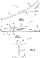
- Figure 1 is an isometric view of a fixed wing aircraft 10 including a fuselage 12, wings 14 and 16, a vertical stabilizer 18 and a horizontal stabilizer 20. It is noted that the aircraft 10 is intended to represent any type of fixed wing aircraft that can benefit from the disclosure below, including single engine aircraft, multi-engine aircraft, prop aircraft, jet engine aircraft, swept-wing aircraft, straight-wing aircraft, commercial aircraft, military aircraft, glider aircraft, commercial aircraft, fighter aircraft, etc.
- Figure 2 is a cross-sectional type view of the aircraft wing 14 including a leading edge 24, a trailing edge 26, an upper wing skin 28 and a lower wing skin 30 all defining an internal chamber 32, where the other wing 16 has the same configuration.
- the thickness of the aircraft skins 28 and 30, the material of the aircraft skins 28 and 30, the length of the wing 14, the width of the wing 14, the size of the chamber 32, etc. can be any shape, dimension, material, parameter, etc. suitable for the purposes discussed herein.
- the wing skins 28 and 30 may be aluminum, graphite composite, etc.
- the wing 14 also includes a main wing spar 36 positioned within the chamber 32 and shown separated from the wing 14 in figure 3 , where the wing spar 36 extends the length or most of the length of the wing 14.
- the wing spar 36 includes an upper spar cap 38 coupled to an inside surface of the upper skin 28, a lower spar cap 40 coupled to an inside surface of the lower skin 30 and a web 42 extending therebetween so that the spar 36 has a general I-beam shape.
- the upper cap 38 can be secured to the skin 28 and the lower cap 40 can be secured to the skin 30 in any suitable manner, such as by a bonding agent, rivets, etc.
- the main wing spar 36 is shown in the chamber 32 as a structural element of the wing 14. However, as will be appreciated by those skilled in the art, other structural elements would likely also be employed, such as spaced apart ribs extending between the leading edge 22 and the trailing edge 24 and being coupled to the spar 36.
- the present disclosure proposes providing an induced or built-in tension in at least the upper spar cap 38. Therefore, when the wing spar 36 is incorporated into the wing 14 and the aircraft 10 is in flight, the residual tension in the upper spar cap 38 will tend to mitigate the compression forces caused by wing bending. The net effect will be to delay the onset of wing buckling that permits the use of wings with higher aspect ratios.
- both of the spar caps 38 and 40 would need to have the built-in tension because if only the upper spar cap 38 was in tension, then the wing 14 would likely "warp" upwards to some degree. Thus, if both of the spar caps 38 and 40 are in equal tension, then the wing 14 will be tension balanced.
- the residual tension load in the lower spar cap 40 will act to accentuate the total tension in the spar cap 40 when the aircraft 10 is in flight. However, this will not be a serious drawback in most cases because the total acceptable tension load tends to be much greater than the load required to induce buckling.
- the spar caps 38 and 40 are configured to have a higher CTE than the web 42 so that they have the built-in tension.
- the main wing spar 36 could be a graphite composite that is thermally cured to give it a desired stiffness, where such a thermally cured graphite composite for an aircraft component typically has a relatively low CTE.
- graphite composite wings are generally fabricated by laying down several carbon fiber ply layers on a tool, where each ply or sheet of the carbon fiber ply layers includes carbon fibers that have been impregnated with a powder resin, and where the fibers are woven into a fabric or tape.
- the stacked ply layers are vacuum compressed and sealed, and the tool and sealed part are then placed in an autoclave or heating oven to thermally cure the resin and form the hardened part.
- Any suitable technique can be employed to provide the higher CTE in the spars 38 and 40.
- a different ply lay-up schedule is used for the spar web 42 than the ply lay-up schedule for the spar caps 38 and 40.
- the fiber direction of the web plies would be tailored to have a CTE near zero, but the spar plies would be configured so their CTE would be much higher.
- Table I below shows various elements having a significant difference in CTE values depending on the direction that the fibers are laid down.
- one type of material can be used for the spar web 42 having a low CTE and another material can be used for the spar caps 38 and 40 having a higher CTE.
- the web 42 is made of a graphite composite having a near zero CTE and the spar caps 38 and 40 are made of fiberglass having a high CTE, a tension load would be induced in the spar caps 38 and 40 after a thermal cure.
- the web 42 can be made of a graphite composite having a near zero CTE and the spar caps 38 and 40 can be made of a metal such has aluminum or titanium.
- the spar caps 38 and 40 are adhesively bonded to the web 42, and the spar 36 is thermally cured so that a tension load is locked into the spar caps 38 and 40 during the cool down from the thermal cure.
- a higher CTE in the spar caps 38 and 40 can be obtained by loading the spar caps 38 and 40 with a high CTE material such as metal particles 44 or metal foils, where the tension load in the spar caps 38 and 40 is induced by a thermal cure of the spar 36.
- a thermal cure is not relied on to obtain the different CTEs.
- the tension load in the spar caps 38 and 40 is induced mechanically.
- the web 42 could be configured to have a near zero CTE and it would be cured without the spar caps 38 and 40.
- the web 42 would be placed in a jig that imposes a longitudinal compression load in the web 42 and the high CTE spar caps 38 and 40 would be attached to the web 42 by mechanical fasteners or by an adhesive.
- the compression load in the web 42 would induce a tension load in the now attached spar caps 38 and 40.
- the spar caps 38 and 40 could be attached to the wing skins 28 and 30 as an assembly prior to attachment to the web 42.
- the spar caps 38 and 40 and the wing skins 28 and 30 would be placed in tension once the web compression load is relieved.
- heating element 46 in figure 2 .
Landscapes
- Engineering & Computer Science (AREA)
- Aviation & Aerospace Engineering (AREA)
- Mechanical Engineering (AREA)
- Moulding By Coating Moulds (AREA)
- Casting Or Compression Moulding Of Plastics Or The Like (AREA)
Applications Claiming Priority (3)
| Application Number | Priority Date | Filing Date | Title |
|---|---|---|---|
| US15/934,327 US10442520B1 (en) | 2018-03-23 | 2018-03-23 | Enhanced wing efficiency via differential thermal coefficient of expansion spar caps |
| EP19710232.0A EP3768591B1 (de) | 2018-03-23 | 2019-02-25 | Verbesserte tragflächeneffizienz über einen differenzialwärmekoeffizienten von expansionsholmgurten |
| PCT/US2019/019362 WO2019182727A1 (en) | 2018-03-23 | 2019-02-25 | Enhanced wing efficiency via differential thermal coefficient of expansion spar caps |
Related Parent Applications (1)
| Application Number | Title | Priority Date | Filing Date |
|---|---|---|---|
| EP19710232.0A Division EP3768591B1 (de) | 2018-03-23 | 2019-02-25 | Verbesserte tragflächeneffizienz über einen differenzialwärmekoeffizienten von expansionsholmgurten |
Publications (2)
| Publication Number | Publication Date |
|---|---|
| EP4458670A2 true EP4458670A2 (de) | 2024-11-06 |
| EP4458670A3 EP4458670A3 (de) | 2024-12-25 |
Family
ID=65724551
Family Applications (2)
| Application Number | Title | Priority Date | Filing Date |
|---|---|---|---|
| EP19710232.0A Active EP3768591B1 (de) | 2018-03-23 | 2019-02-25 | Verbesserte tragflächeneffizienz über einen differenzialwärmekoeffizienten von expansionsholmgurten |
| EP24201344.9A Pending EP4458670A3 (de) | 2018-03-23 | 2019-02-25 | Erhöhte flügeleffizienz über einen differentiellen thermischen koeffizienten von expansionsholmgurten |
Family Applications Before (1)
| Application Number | Title | Priority Date | Filing Date |
|---|---|---|---|
| EP19710232.0A Active EP3768591B1 (de) | 2018-03-23 | 2019-02-25 | Verbesserte tragflächeneffizienz über einen differenzialwärmekoeffizienten von expansionsholmgurten |
Country Status (3)
| Country | Link |
|---|---|
| US (1) | US10442520B1 (de) |
| EP (2) | EP3768591B1 (de) |
| WO (1) | WO2019182727A1 (de) |
Family Cites Families (14)
| Publication number | Priority date | Publication date | Assignee | Title |
|---|---|---|---|---|
| GB793443A (en) | 1954-07-28 | 1958-04-16 | Cobactor Kingsway Ltd | Improvements in structural members |
| US4662587A (en) * | 1981-09-30 | 1987-05-05 | The Boeing Company | Composite for aircraft wing and method of making |
| DE4329744C1 (de) * | 1993-09-03 | 1994-09-08 | Deutsche Forsch Luft Raumfahrt | Flügel mit Flügelschalen aus Faserverbundwerkstoffen, insbesondere CFK, für Luftfahrzeuge |
| DE19509340C2 (de) | 1995-03-15 | 1998-12-03 | Daimler Benz Aerospace Airbus | Strukturelement |
| US5688426A (en) | 1995-06-07 | 1997-11-18 | The Boeing Company | Hybrid metal webbed composite beam |
| WO1998015455A1 (fr) | 1996-10-07 | 1998-04-16 | Xinyun Wang | Structure precontrainte destinee a un avion et son procede de fabrication |
| US6979050B2 (en) | 2003-12-04 | 2005-12-27 | General Motors Corporation | Airflow control devices based on active materials |
| ES2263324B1 (es) | 2004-03-18 | 2007-11-01 | Manuel Torres Martinez | Procedimiento para la fabricacion de fuselajes de aeronaves y dispositivo para llevar a cabo dicho procedimiento. |
| WO2006080832A1 (en) * | 2005-01-25 | 2006-08-03 | Technische Universiteit Delft | Actuator |
| US9144944B1 (en) | 2010-09-09 | 2015-09-29 | Groen Brothers Aviation, Inc. | Rotor blade spar manufacturing apparatus and method |
| US9156559B2 (en) * | 2011-10-19 | 2015-10-13 | The Boeing Company | Segmented aircraft wing having solar arrays |
| GB201207525D0 (en) | 2012-04-30 | 2012-06-13 | Airbus Operations Ltd | Morphing aerofoil |
| EP2815958A1 (de) | 2013-06-18 | 2014-12-24 | Airbus Operations GmbH | Strukturelement und zugehöriges Verfahren |
| JP6690910B2 (ja) | 2014-10-09 | 2020-04-28 | ザ・ボーイング・カンパニーThe Boeing Company | 複合材と金属との接合部を有する複合材構造体、及びその製造方法 |
-
2018
- 2018-03-23 US US15/934,327 patent/US10442520B1/en active Active
-
2019
- 2019-02-25 WO PCT/US2019/019362 patent/WO2019182727A1/en not_active Ceased
- 2019-02-25 EP EP19710232.0A patent/EP3768591B1/de active Active
- 2019-02-25 EP EP24201344.9A patent/EP4458670A3/de active Pending
Also Published As
| Publication number | Publication date |
|---|---|
| EP3768591B1 (de) | 2024-10-09 |
| US20190291844A1 (en) | 2019-09-26 |
| WO2019182727A1 (en) | 2019-09-26 |
| EP4458670A3 (de) | 2024-12-25 |
| US10442520B1 (en) | 2019-10-15 |
| EP3768591A1 (de) | 2021-01-27 |
Similar Documents
| Publication | Publication Date | Title |
|---|---|---|
| US10556662B2 (en) | Rotary wing aircraft with a fuselage that comprises at least one structural stiffened panel | |
| Ghori et al. | The role of advanced polymer materials in aerospace | |
| CA2834751C (en) | Aircraft structure for high capacity pull off | |
| US8763253B2 (en) | Vertical laminate noodle for high capacity pull-off for a composite stringer | |
| CN104245295B (zh) | 具有倾斜腹板的帽形加强筋和形成帽形加强筋的方法 | |
| US8709584B2 (en) | Composite aircraft floor system | |
| CA2658240C (en) | Composite wing slat for aircraft | |
| US10308345B2 (en) | Structure | |
| US9302446B2 (en) | Skin-stiffened composite panel | |
| US9862477B2 (en) | Aircraft structure | |
| US20150217850A1 (en) | Laminated i-blade stringer | |
| US9034453B2 (en) | Reinforced aircraft fuselage panel and method of manufacture | |
| WO2020016553A1 (en) | Wing structure | |
| EP4458670A2 (de) | Erhöhte flügeleffizienz über einen differentiellen thermischen koeffizienten von expansionsholmgurten | |
| US11400662B2 (en) | Method for manufacturing a stiffened structural panel for an aircraft | |
| CN221187701U (zh) | 一种树脂基复合材料板材及制件 |
Legal Events
| Date | Code | Title | Description |
|---|---|---|---|
| PUAI | Public reference made under article 153(3) epc to a published international application that has entered the european phase |
Free format text: ORIGINAL CODE: 0009012 |
|
| STAA | Information on the status of an ep patent application or granted ep patent |
Free format text: STATUS: THE APPLICATION HAS BEEN PUBLISHED |
|
| AC | Divisional application: reference to earlier application |
Ref document number: 3768591 Country of ref document: EP Kind code of ref document: P |
|
| AK | Designated contracting states |
Kind code of ref document: A2 Designated state(s): AL AT BE BG CH CY CZ DE DK EE ES FI FR GB GR HR HU IE IS IT LI LT LU LV MC MK MT NL NO PL PT RO RS SE SI SK SM TR |
|
| REG | Reference to a national code |
Ref country code: DE Ref legal event code: R079 Free format text: PREVIOUS MAIN CLASS: B64C0031020000 Ipc: B64C0003180000 |
|
| PUAL | Search report despatched |
Free format text: ORIGINAL CODE: 0009013 |
|
| AK | Designated contracting states |
Kind code of ref document: A3 Designated state(s): AL AT BE BG CH CY CZ DE DK EE ES FI FR GB GR HR HU IE IS IT LI LT LU LV MC MK MT NL NO PL PT RO RS SE SI SK SM TR |
|
| RIC1 | Information provided on ipc code assigned before grant |
Ipc: B32B 15/14 20060101ALI20241121BHEP Ipc: B64C 3/20 20060101ALI20241121BHEP Ipc: B64C 3/18 20060101AFI20241121BHEP |
|
| STAA | Information on the status of an ep patent application or granted ep patent |
Free format text: STATUS: REQUEST FOR EXAMINATION WAS MADE |
|
| 17P | Request for examination filed |
Effective date: 20250218 |
|
| STAA | Information on the status of an ep patent application or granted ep patent |
Free format text: STATUS: EXAMINATION IS IN PROGRESS |
|
| 17Q | First examination report despatched |
Effective date: 20250930 |
|
| GRAP | Despatch of communication of intention to grant a patent |
Free format text: ORIGINAL CODE: EPIDOSNIGR1 |
|
| STAA | Information on the status of an ep patent application or granted ep patent |
Free format text: STATUS: GRANT OF PATENT IS INTENDED |
|
| RIC1 | Information provided on ipc code assigned before grant |
Ipc: B64C 3/18 20060101AFI20260108BHEP Ipc: B64C 3/20 20060101ALI20260108BHEP Ipc: B64C 3/26 20060101ALI20260108BHEP Ipc: B64C 3/42 20060101ALI20260108BHEP Ipc: B64C 31/02 20060101ALI20260108BHEP Ipc: B32B 15/14 20060101ALI20260108BHEP |