EP4458337B1 - Absorbierender artikel mit quersperren gegen lecks - Google Patents
Absorbierender artikel mit quersperren gegen lecks Download PDFInfo
- Publication number
- EP4458337B1 EP4458337B1 EP24172809.6A EP24172809A EP4458337B1 EP 4458337 B1 EP4458337 B1 EP 4458337B1 EP 24172809 A EP24172809 A EP 24172809A EP 4458337 B1 EP4458337 B1 EP 4458337B1
- Authority
- EP
- European Patent Office
- Prior art keywords
- absorbent
- nonwoven
- transversal
- barrier
- elastic
- Prior art date
- Legal status (The legal status is an assumption and is not a legal conclusion. Google has not performed a legal analysis and makes no representation as to the accuracy of the status listed.)
- Active
Links
Images


Classifications
-
- A—HUMAN NECESSITIES
- A61—MEDICAL OR VETERINARY SCIENCE; HYGIENE
- A61F—FILTERS IMPLANTABLE INTO BLOOD VESSELS; PROSTHESES; DEVICES PROVIDING PATENCY TO, OR PREVENTING COLLAPSING OF, TUBULAR STRUCTURES OF THE BODY, e.g. STENTS; ORTHOPAEDIC, NURSING OR CONTRACEPTIVE DEVICES; FOMENTATION; TREATMENT OR PROTECTION OF EYES OR EARS; BANDAGES, DRESSINGS OR ABSORBENT PADS; FIRST-AID KITS
- A61F13/00—Bandages or dressings; Absorbent pads
- A61F13/15—Absorbent pads, e.g. sanitary towels, swabs or tampons for external or internal application to the body; Supporting or fastening means therefor; Tampon applicators
- A61F13/45—Absorbent pads, e.g. sanitary towels, swabs or tampons for external or internal application to the body; Supporting or fastening means therefor; Tampon applicators characterised by the shape
- A61F13/49—Absorbent pads, e.g. sanitary towels, swabs or tampons for external or internal application to the body; Supporting or fastening means therefor; Tampon applicators characterised by the shape specially adapted to be worn around the waist, e.g. diapers, nappies
- A61F13/494—Absorbent pads, e.g. sanitary towels, swabs or tampons for external or internal application to the body; Supporting or fastening means therefor; Tampon applicators characterised by the shape specially adapted to be worn around the waist, e.g. diapers, nappies characterised by edge leakage prevention means
- A61F13/49406—Absorbent pads, e.g. sanitary towels, swabs or tampons for external or internal application to the body; Supporting or fastening means therefor; Tampon applicators characterised by the shape specially adapted to be worn around the waist, e.g. diapers, nappies characterised by edge leakage prevention means the edge leakage prevention means being at the crotch region
- A61F13/49446—Absorbent pads, e.g. sanitary towels, swabs or tampons for external or internal application to the body; Supporting or fastening means therefor; Tampon applicators characterised by the shape specially adapted to be worn around the waist, e.g. diapers, nappies characterised by edge leakage prevention means the edge leakage prevention means being at the crotch region the edge leakage prevention means being an impermeable sheet or impermeable part of a sheet placed on or under the top sheet
-
- A—HUMAN NECESSITIES
- A61—MEDICAL OR VETERINARY SCIENCE; HYGIENE
- A61F—FILTERS IMPLANTABLE INTO BLOOD VESSELS; PROSTHESES; DEVICES PROVIDING PATENCY TO, OR PREVENTING COLLAPSING OF, TUBULAR STRUCTURES OF THE BODY, e.g. STENTS; ORTHOPAEDIC, NURSING OR CONTRACEPTIVE DEVICES; FOMENTATION; TREATMENT OR PROTECTION OF EYES OR EARS; BANDAGES, DRESSINGS OR ABSORBENT PADS; FIRST-AID KITS
- A61F13/00—Bandages or dressings; Absorbent pads
- A61F13/15—Absorbent pads, e.g. sanitary towels, swabs or tampons for external or internal application to the body; Supporting or fastening means therefor; Tampon applicators
- A61F13/45—Absorbent pads, e.g. sanitary towels, swabs or tampons for external or internal application to the body; Supporting or fastening means therefor; Tampon applicators characterised by the shape
- A61F13/49—Absorbent pads, e.g. sanitary towels, swabs or tampons for external or internal application to the body; Supporting or fastening means therefor; Tampon applicators characterised by the shape specially adapted to be worn around the waist, e.g. diapers, nappies
- A61F13/494—Absorbent pads, e.g. sanitary towels, swabs or tampons for external or internal application to the body; Supporting or fastening means therefor; Tampon applicators characterised by the shape specially adapted to be worn around the waist, e.g. diapers, nappies characterised by edge leakage prevention means
- A61F13/49466—Absorbent pads, e.g. sanitary towels, swabs or tampons for external or internal application to the body; Supporting or fastening means therefor; Tampon applicators characterised by the shape specially adapted to be worn around the waist, e.g. diapers, nappies characterised by edge leakage prevention means the edge leakage prevention means being at the waist region
Definitions
- the present disclosure is directed to an absorbent article for personal hygiene, typically in the form of pants (such as for babies, youths or adults) and generally of the disposable kind as well as the method for the manufacture of such absorbent articles and the apparatus to carry out such method.
- the front and back panels are joined together to define a pair of side seams, and at least a portion of said absorbent insert proximal to the front and/or back transversal edges thereof comprises a transversal waist barrier comprising a substantially liquid impermeable film layer.
- each hydrophobic nonwoven is a multi-layer nonwoven comprising at least two, preferably at least three, layers selected from a spunbond nonwoven and a meltblown nonwoven, more preferably said nonwoven being selected from a spunbond-meltblown nonwoven, a spunbond-meltblown-spunbond nonwoven, and a spunbond-meltblown-meltblown-spunbond nonwoven.
- the film and/or elastic strands form an elastic area where the total area of patch or discrete layer is greater than the elastic area, meaning the total area where the film and/or sum of elastic strands are arranged, said total area of patch or discrete layer preferably comprising an inelastic area outboard of the elastic area and substantially encircling or enclosing it, e.g. the inelastic area substantially follows the perimeter of the patch or discrete layer for example the inelastic are could be a void free of elastic film and/or strands, or comprise de-activated elastic material such as elastic material rendered inelastic by technic such as cutting or melting. Such arrangement enables to ensure a better attachment or anchoring of the elastic film and/or strands since joining would occur in areas free of additional ondulations or wrinkles.
- the disclosure relates to a method for the manufacture of an absorbent article as described hereabove, said method comprising the, preferably sequential, steps of:
- the disclosure relates to a method for the manufacture of an absorbent article comprising the steps of: providing a front panel; providing a back panel; providing an absorbent insert comprising front and back transversal edges and left and right longitudinal edges connecting the front and back transversal edges to form a perimeter thereof and generally wherein the left and right longitudinal edges extend substantially along the longitudinal axis y and are oppositely disposed such that said longitudinal axis y extends therebetween, and the front and back transversal edges extend substantially along the transversal axis x, and typically substantially perpendicular to the longitudinal axis y, and are oppositely disposed such that said transverse axis x extends therebetween); folding a portion of said absorbent insert proximal to the front and/or back transversal edges thereof onto itself, preferably in the shape of a substantially U-fold, to form transversal waist barrier(s); joining said insert to said front and back panels; and joining said front and back panels together along a pair of oppositely disposed side seams.
- the method further comprising the step of arranging an elastic material over the folded portion of the folded absorbent insert prior to step of folding an outer nonwoven layer of the front and/or back panels over the folded absorbent insert.
- the elastic material is arranged such that said elastic material is sandwiched between the absorbent insert and the outer nonwoven layer.
- the absorbent insert comprises a backsheet and eventually an outer cover on the garment facing surface of the absorbent core, the elastic material being sandwiched between the backsheet and the outer nonwoven layer or the elastic material being sandwiched between the outer cover and the outer nonwoven layer or the elastic material being sandwiched between the backsheet and outer cover and the outer nonwoven layer e.g. in cases where the outer cover is transversally shorter than the backsheet.
- the elastic material is directly or indirectly joined to the backsheet, preferably by adhesive, and sandwiched between the backsheet and/or outer cover and the outer nonwoven layer.
- the method further comprising the step of applying adhesive onto said portion of the absorbent insert proximal to the front and/or back transversal edges in an adhesive pattern, said adhesive pattern comprising at least two areas of adhesive arranged at the transversal extremities of the front and/or back transversal edges, a further area of adhesive extending transversally between said two areas of adhesive, said further area being at a longitudinal distance from the transversal edge, and an adhesive-free area arranged between the transversal edge of the absorbent insert and said further area.
- the disclosure relates to an apparatus for the manufacture of an absorbent article according to a method as described herein wherein the apparatus comprises:
- the pressing blade comprise a sloped portion at the upstream portion of the pressing blade with respect to the machine direction, said sloped portion extending diagonally downward while extending downstream with respect to the machine direction.
- the apparatus comprises an adhesive dispensing device arranged upstream of the folding unit with respect to the machine direction, said device being configured to apply adhesive intermittently.
- a pressure roller is arranged to press the folded transversal edge of the absorbent insert, said pressure roller being arranged downstream of the folding unit and upstream of the rotating drum and/or second conveyor belt with respect to the machine direction.
- the folding unit comprises a support device to carry the folding blade and/or pressing blade said support device comprising means to move the folding blade and/or pressing blade or comprising means to remove the folding blade and/or pressing blade, preferably in the cross and/or vertical directions (CD,Z).
- a compartment refers to one or more than one compartment.
- % by weight refers to the relative weight of the respective component based on the overall weight of the formulation.
- the term "absorbent article” refers to disposable devices such as infant or adult diapers or pads, pants, training pants, and the like which are placed against or in proximity to the body of the wearer to absorb and contain the various exudates discharged from the body.
- these articles comprise a topsheet, backsheet, an absorbent core and optionally an acquisition system (which may be comprised of one or several layers) and typically other components, with the absorbent core normally placed between the backsheet and the acquisition system or topsheet.
- absorbent articles of the disclosure will be further illustrated in the below description and in the Figures, though all embodiments described herein may equally be applied onto absorbent articles in the form of pants (or even in the form of feminine hygiene articles such as menstrual pants and/or slips/panties). None in this description should be however considered limiting the scope of the claims unless explicitly indicated otherwise. Unless indicated otherwise, the description refers to the dry article, i.e. before use and conditioned at least 24 hours at 21° C.+/-2° C. and 50+/-20% Relative Humidity (RH).
- RH Relative Humidity
- nonwoven web as used herein means a manufactured sheet, web or batt of directionally or randomly orientated fibers, bonded by friction, and/or cohesion and/or adhesion, excluding paper and products which are woven, knitted, tufted, stitch-bonded incorporating binding yarns or filaments, or felted by wet-milling, whether or not additionally needled.
- the fibers may be of natural or man-made origin and may be staple or continuous filaments or be formed in situ.
- absorbent material it is meant a material which has some absorbency property or liquid retaining properties, such as SAP, cellulosic fibers as well as synthetic fibers, most preferably is selected from the group consisting of SAP, cellulose (or cellulosic) fibers, and mixtures thereof.
- absorbent materials in the form of fibrous absorbent materials have been found to be useful. These fibrous absorbent materials can comprise or consist of natural fibers, e.g. cellulosic fibers as well as synthetic fibers.
- glues used in making absorbent cores have no absorbency properties and are not considered as absorbent material.
- the term "absorbent core” refers to the component or components of the article having the most absorbent capacity and comprising an absorbent material and optionally a core wrap enclosing the absorbent material.
- the term “absorbent core” does not include the acquisition-distribution system or layer or any other component of the article which is not either integral part of the core wrap or placed within the core wrap.
- the core may consist essentially of, or consist of, a core wrap, absorbent material as defined below and glue enclosed within the core wrap.
- Absorbent articles (1) herein are for personal hygiene, preferably a disposable pant, and comprise:
- the article comprises a transversal waist barrier (5) proximal to the front and/or back transversal edges of the absorbent insert (4) wherein said barrier (5) comprises a plurality of liquid retarding layers wherein said plurality of liquid retarding layers comprise at least two layers selected from the group consisting of hydrophobic nonwovens, films, and/or strands (preferably wherein at least one of said at least two layers is a film, more preferably a substantially liquid impermeable film); and wherein at least a majority of the waist barrier (5) comprises at least two of said plurality of liquid retarding layers and wherein said at least two of said plurality of liquid retarding layers are un-joined at one or more locations so that said layers are separated from one another at said location(s) by a gap (G), and preferably wherein said one or more locations together correspond to a majority of a total surface of said waist barrier (5).
- said barrier (5) comprises a plurality of liquid retarding layers wherein said plurality of liquid retarding layers comprise at least two layers selected
- Such a gap or gaps are generally formed by ensuring that when the liquid retarding layers (e.g. hydrophobic nonwovens as described herein, like between inner and outer layers of the front and/or back panel(s) as described herein) are joined together, they are joined at discrete locations (e.g.
- the core (8) may comprise one or more channels (13), preferably substantially free of absorbent material; each said channel generally being circumscribed by absorbent material.
- the absorbent core may comprise a core wrap to enclose the absorbent material, and the channel(s) may be formed by joining top and bottom layers of said core wrap together (any suitable joining technique may be used such as via adhesive and/or mechanical bonding such as heat and/or pressure bonding, ultrasonic bonding and the like).
- the core wrap may be made of any suitable nonwoven such as spunbond and/or meltblown nonwoven; and/or a carded nonwoven such as a carded air-through-bonded nonwoven or a carded calender-bonded nonwoven; such nonwovens particularly preferred in case of absence of an optional acquisition distribution layer between the core/core wrap and topsheet.
- the channel(s) herein may have a width (generally extending substantially parallel to the transverse x axis or centerline) of from 5mm to 30mm, preferably from 10mm to 25mm.
- the channel(s) may have a length (generally extending substantially parallel to the longitudinal y axis or centerline) that is from 10% to 80%, preferably from 15% to 75%, even more preferably from 20% to 70%, of a total length of the absorbent core (8) [when multiple disconnected channels along the y axis are present the % length is the sum of the length of each said channels divided by the total absorbent core length].
- the channel(s) may have a variety of shapes depending on the intended purpose for example can have any of the shapes described in EP3453368 .
- Fig. 19 further illustrates exemplary channels.
- Advantageously channels according to the above embodiment may aid to promote fast liquid distribution therealong thus improving acquisition speed performance of the article whilst mitigating against risks of leakage.
- the core (8) may comprise a recessed region (R) proximal and/or adjacent to the barrier (5).
- Fig.19 exemplifies an embodiment of such recessed region.
- the recessed region may be a region that has a lower basis weight of absorbent material compared to the rest of the absorbent core (8) or may even be substantially free of absorbent material; alternatively albeit less preferred, the recessed region may comprise compressed absorbent material such as by embossing or other similar technique.
- the recessed region (R) may be partly enclosed by absorbent material [or of higher basis weight thereof] such that said absorbent material of the core (8) defines and/or delimits at least a portion of said recessed region (R).
- the recessed region may be in the form of an arc or similar geometry, including for example with curved and/or linear edges forming a substantial C-shape, U-shape, or V-shape; all also contemplated and within the meaning herein.
- Advantageously such recessed region may not only allow to increase the volume available for the pocket formed by the barrier but further allows the barrier to better form a standing gather and thus form a larger opening for exudate collection therein.
- the recessed region (R) may be centrally located relative to the absorbent core, as exemplarily shown in one form thereof in Fig.19 .
- the gluteal cleft is centrally located on the body, hence the central location of the recessed region being preferred, moreover, the generally lower thickness of the recessed region results in the pocket formed under the barrier not only having more volume to more efficiently gather bodily exudates as explained above but further when a user wears the absorbent article and subsequently puts pressure on the absorbent core by means of sitting, lying down or any other way, the recessed region will contribute to being exposed to a lower pressure compared to the surrounding areas of the article which may result in that the surrounding parts of the article will have a pressure receiving function, as a consequence, the bodily exudates will flow into the pocket.
- the largest width of the recessed region is greater than the width of the channel(s), preferably is at least 150% greater, more preferably at least 200% greater, even more preferably from 2.5 to 9, even more preferably from 4 to 9, times greater than the width of the channel(s) (13).
- the largest width of the recessed region (R) may be at least 15mm, preferably 20mm, even more preferably from 25mm to 90mm, even more preferably from 40mm to 90mm.
- this may allow for maximised pocket volume and pressure relief without compromising on acquisition speed and absorption capacity.
- both a recessed region (R) and channel(s) (13) are present, they are mutually separated by absorbent material generally such that the channel(s) are not directly connected to the recessed region but are rather spaced apart therefrom.
- the distance between the channel(s) and the recessed region may be greater or equal to the width of the channel(s).
- risk of exudate leakage, especially urine is reduced as separation by the absorbent material prevents urine that is being effectively ducted along the channels from entering the pocket.
- the front and back panels (2, 3) are refastenably joined together to define the pair of side seams such that the seams can be opened and re-closed, preferably wherein the seams are maintained in closed state by one or more cooperating male and female fasteners preferably hook and loop fasteners respectively.
- the barrier described herein is particularly effective when combined with a refastenable pant in that exudates collected in the barrier can be wrapped during removal from the subject and fastened in a closed/enclosed state for disposal in an easy manner.
- the article may have a Seepage Index of less than 35%, preferably of less than 30%, preferably less than 25%, more preferably less than 20%, even more preferably less than 10%, even more preferably from 0% to 5%, according to the Seepage Index Method herein.
- the transversal waist barrier (5) is a laminate comprising an elastic film or a plurality of elastic strands sandwiched between said hydrophobic nonwoven that can be a single hydrophobic nonwoven that is folded to sandwich said elastic film or strands, or a plurality of hydrophobic nonwovens sandwiching said film or strands therebetween; and preferably said elastic film or stands being sandwiched between two hydrophobic nonwovens (or layers).
- the barrier (5) comprises three or more of said liquid retarding layers (preferably each being a hydrophobic nonwoven as described herein) at least over a portion of said barrier (5), an exemplary embodiment is illustrated in Fig.18D .
- Advantageously structures with such multiple layers in combination with the described gap allows for an effective exudate barrier even when not utilising a substantially liquid impermeable film.
- the waist barrier (5) preferably comprises at least two hydrophobic nonwovens intermittently joined together by adhesive, preferably by one or more elastic strands that are strand-coated with adhesive and sandwiched therebetween.
- adhesive preferably by one or more elastic strands that are strand-coated with adhesive and sandwiched therebetween.
- this allows to maximise the un-joined region(s) that generally form the gap(s) referred to herein and hence minimising contact between layers.
- the nonwovens need not be solely or exclusively joined together by said strand-coated elastics but further joining means such as further adhesive areas or discrete bonding such as mechanical bonding may also be used yet preferably taking care that not the entire respective surfaces of the nonwovens are joined together so as to maintain un-joined regions within the barrier construct.
- the front and/or back panels (2, 3) preferably comprise a plurality of elastic strands (11) sandwiched between two or more hydrophobic nonwoven layers, said nonwoven layers comprising at least an inner nonwoven (NW1) and an outer nonwoven (NW2) that are substantially congruent with each other to form a front and/or back panel laminate (PL); and wherein the front and/or back panel laminate (PL) is folded onto itself to form the barrier (5) and such that both the inner and outer nonwovens (NW1, NW2) are folded at one or more positions.
- Figs.18A-D are particularly representative of such exemplary embodiments.
- substantially congruent does not require said layers to be entirely congruent, it is rather advantageous, encompassed in its meaning, and/or preferred that one of the layers (preferably the inner nonwoven layer (NW1)) is somewhat shorter than the other (preferably the outer nonwoven layer (NW2)) such that a flange (FLA) is formed that can be folded and joined to the said other layer (preferably the outer nonwoven layer (NW2)) generally to securely contain the elastics (11) securely with limited risk of irritation to the wearer in case of snap-back, yet generally retaining a portion of said other layer within the fold so as to create a further buffer to restrict leakage of exudates.
- the layers preferably the inner nonwoven layer (NW1)
- the outer nonwoven layer (NW2) preferably the outer nonwoven layer (NW2)
- the barrier (5) is arranged such that the folded outer nonwoven (NW2) comes into direct contact with the skin of the wearer when the article is in use. At least a portion of the inner nonwoven (NW1) may be in direct contact with the skin of the wearer when the article is in use, typically in at least some regions of the front and/or back panels other than the barrier (5).
- At least the inner nonowoven (NW1) is preferably a multi-layer nonwoven comprising at least two, preferably at least three, layers selected from a spunbond nonwoven and a meltblown nonwoven, more preferably said nonwoven being selected from a spunbond-meltblown nonwoven, a spunbond-meltblown-spunbond nonwoven, and a spunbond-meltblown-meltblown-spunbond nonwoven.
- Such laminates are advantageous in terms of mechanical properties but may have drawbacks in terms of softness.
- the second elastic region (ER2) preferably comprises a plurality of spaced-apart elastic strands (11) having one or more second strand spacings (ss2) and wherein the first and second strand spacings are different, preferably wherein the first strand spacing(s) (ss1) is greater than the second strand spacing(s) (ss2), more preferably wherein the barrier (5) comprises said second elastic region (ER2).
- this aids to create a tension differential that may help the barrier (5) to stand up to form a transversal up-standing gather or cuff.
- At least one of the elastic strands of the second elastic region (ER2) is coloured so that the barrier (5) is visually discernable from the rest of the article. This may advantageously aid a caregiver to identify the front and back orientation of the article to put onto the subject, especially in case of asymmetric positioning of the elastics in the front vs back and/or the presence of the barrier (5) at only one of the front or back panels.
- the outer nonwoven (NW2) is joined to the inner nonwoven (NW1) at a first fold position (FP1), and wherein the inner nonwoven (NW1) is joined to itself at a second fold position (FP2), preferably wherein the first fold position (FP1) and the second fold position (FP2) are different, more preferably wherein the first and second fold positions (FP1, FP2) do not overlap.
- the outer nonwoven may be joined to the inner nonwoven at the first fold position (FP1) preferably by a first adhesive (A1).
- the inner nonwoven (NW1) may be joined to itself at a second fold position (FP2) preferably by a second adhesive (A2).
- the absorbent insert (4) may be joined to the inner nonwoven (NW1) by a third adhesive (A3).
- the first, second and third adhesives (A1, A2, A3) may be the same or different.
- at least the second adhesive (A2) (and the fourth adhesive (A4) as described below, when present) is hydrophobic, which generally can advantageously help to prevent low viscosity exudates from penetrating out of the pocket nonwoven materials.
- the adhesive such as the hydrophobic adhesive, may be a hot melt adhesive.
- a hot melt adhesive is hydrophobic, a portion of the hot melt adhesive is molten and spread on an even, horizontal surface, such as a table, to form a film. Then a drop of water is applied on the film and the contact angle is determined, as is well known in the art.
- the adhesive is hydrophobic, if the contact angle is of more than 90°.
- the second adhesive (A2) is applied continuously in a transverse direction (i.e. substantially parallel to the transverse axis x).
- a further fourth adhesive (A4) is preferably applied in a lengthwise direction (i.e. substantially parallel to the longitudinal axis y) of the barrier (5), said fourth adhesive (A4) being applied discontinuously in a transverse direction such that an un-joined pocket opening is formed therebetween for collecting and/or retaining exudates therein, preferably said fourth adhesive (A4) being positioned outboard and/or peripheral to the said pocket opening.
- discrete bonding elements may be used to fasten the folded outer nonwoven (NW2) to the inner nonwoven (NW1) at positions outboard of the fourth adhesive (A4).
- the discrete bonding elements may be formed by intermittent application of adhesive or more preferably by mechanical bonding techniques as are known in the art such as pressure and heat bonding, ultrasonic bonding and the like.
- a maximum distance (d2max) between a terminal edge (TE) of said waist barrier (4) corresponding to and/or forming a pocket opening and a closest terminal edge (TEa) of the absorbent core (8) is less than 20 mm, preferably less than 17 mm, even more preferably from 0mm to 15 mm.
- a capillary acceleration sheet is comprised along substantially an entire maximum distance (d2max), preferably along the entire said maximum distance, such that a fluid communication bridge is formed between at least the barrier (5) and the absorbent core (8).
- the capillary acceleration sheet may thus enable wicking of the body exudates therealong and towards the absorbent core that may then absorb the exudates even against gravity as the case may be depending on body position of the wearer.
- the capillary acceleration sheet is preferably a nonwoven, more preferably the nonwoven comprising, or consisting of, a carded air-through-bonded nonwoven or a spunbond nonwoven. Most preferred are nonwovens comprising an embossment pattern and/or apertures, hence in such embodiments the nonwoven comprises an embossment pattern and/or apertures.
- the capillary acceleration sheets herein may be comprised (or even formed entirely) of the topsheet of the absorbent article that is typically comprised by the insert, alternatively or in addition it may be an acquisition distribution layer that generally protracts so as to extend substantially along the entire distance d2max.
- an acquisition distribution layer that generally protracts so as to extend substantially along the entire distance d2max.
- the absorbent core (8) comprises cellulose fibers and said cellulose fibers are comprised at a level of at least 10%wt, preferably at least 12%wt, more preferably at least 15%wt, even more preferably at least 20%wt, even more preferably from 22%wt to 40%wt, by weight of the absorbent core.
- the cellulose further acts as wicking material that aids to carry exudates from the pocket into the core by capillary action before being absorbed by superabsorbent polymer particles as described herein.
- the combination of a capillary acceleration sheet as described herein above in combination with an absorbent core comprising the above recited amounts of cellulose fibers allow for a synergistic cooperation that enhances the exudate draining properties of pockets described herein.
- the transversal waist barrier (5) comprises a film (typically joined to one or two nonwovens as described in more detail in embodiments herein).
- the film preferably extends over the majority of the waist barrier (5) or even has a total surface area that substantially corresponds to that of the barrier (5). It being understood that in embodiments herein where the barrier (5) is formed by folding of the insert the film surface area compared to the barrier (5) surface area may be greater than if the barrier (5) is formed by means of a patch in other embodiments herein; yet maintaining similar advantages being better leakage prevention especially at different body positions, sweat and the like that a wearer may subject the absorbent article to.
- a maximum distance (d1max) between a terminal transversal edge (TT) of said waist barrier (4) corresponding to and/or forming a closed-end of said pocket and a closest terminal edge (TEa) of the absorbent core (8) is less than 80 mm, preferably less than 60 mm, even more preferably less than 50 mm, even more preferably from 0mm to 20mm.
- TT terminal transversal edge
- TEa closest terminal edge
- the ratio d1max/ d2max is greater than 2.5, preferably greater than 3.0, even more preferably from 3.5 to 50.
- this allows for a balance between pocket size for capturing exudates therein and ability for exudates to be drained from the pocket to limit leakage that could arise for example upon application of pressure if not drained and absorbed by the core.
- absorbent articles herein are for personal hygiene, preferably in the form of a pant, the absorbent article comprising: a substantially transversely extending front panel (2); a substantially transversely extending back panel (3); and a substantially longitudinally extending absorbent insert (4) joined to each of said front and back panels (2, 3), said absorbent insert (4) comprising front and back transversal edges and left and right longitudinal edges connecting the front and back transversal edges to form a perimeter thereof (generally wherein the left and right longitudinal edges extend substantially parallel to the longitudinal axis y and are oppositely disposed such that said longitudinal axis y extends therebetween, and the front and back transversal edges extend substantially parallel to the transversal axis x, and typically substantially perpendicular to the longitudinal axis y, and are oppositely disposed such that said transverse axis x extends therebetween); the absorbent insert (4) preferably comprising an absorbent core (8);
- the substantially liquid impermeable film layer may be an integral component of at least one element or portion of the absorbent article such as a backsheet (7) thereof typically such that no additional and/or separate layer, element and/or material is incorporated to form the transversal waist barrier(s) (5).
- a backsheet (7) typically such that no additional and/or separate layer, element and/or material is incorporated to form the transversal waist barrier(s) (5).
- this allows to reduce waste and/or cost associated with incorporating separate elements to create the transversal waist barrier(s).
- the backsheet (7) is generally that portion of the absorbent article positioned adjacent the garment-facing surface of the absorbent core (8) and which prevents the exudates absorbed and contained therein from soiling articles such as bedsheets and undergarments.
- the backsheet (7) is typically impermeable to liquids (e.g. urine).
- the backsheet (7) may for example be or comprise a thin plastic film such as a thermoplastic film having a thickness of about 0.012 mm to about 0.051 mm.
- the basis weight of the backsheet (7) is less than or equal to 16 g/m 2 , more preferably from 10 g/m 2 to 14 g/m 2 .
- Exemplary backsheet films include those manufactured by Tredegar Corporation, based in Richmond, Va., and sold under the trade name CPC2 film.
- Other suitable backsheet materials may include breathable materials which permit vapors to escape from the absorbent article while still preventing exudates from passing through the backsheet (7).
- Exemplary breathable materials may include materials such as woven webs, nonwoven webs, composite materials such as film-coated nonwoven webs, microporous films such as manufactured by Mitsui Toatsu Co., of Japan under the designation ESPOIR NO and by Tredegar Corporation of Richmond, Va., and sold under the designation EXAIRE, and monolithic films such as manufactured by Clopay Corporation, Cincinnati, Ohio under the name HYTREL blend P18-3097.
- the backsheet (7) is breathable.
- Breathable backsheet herein typically means that it comprises micro-openings sized to allow at least some water vapour to permeate through the backsheet that typically comprises a film such as a polyethylene (PE) film.
- PE polyethylene
- a backsheet (7) is breathable when the water vapour transmission rate (WVTR) of the backsheet is at least 500 grams/m2 - 24 hours, preferably at least 1,000 grams/m2 - 24 hours, even more preferably from 1,200 grams/m2 - 24 hours to 2,500 grams/m2 - 24 hours, even more preferably from 1,500 grams/m2 - 24 hours to 2,100 grams/m2 - 24 hours, as measured according to ASTM D6701-21.
- WVTR water vapour transmission rate
- the backsheet (7) may be joined to the topsheet (6), the absorbent core (8) or any other element of the absorbent article by any attachment means known in the art.
- Suitable attachment means are described above with respect to means for joining the topsheet to other elements of the article.
- the attachment means may include a uniform continuous layer of adhesive, a patterned layer of adhesive, or an array of separate lines, spirals, or spots of adhesive. Adhesives which have been found to be satisfactory are manufactured by H. B. Fuller Company of St. Paul, Minn. and marketed as HL-1620 and HL 1358-XZP.
- the attachment means may comprise heat bonds, pressure bonds, ultrasonic bonds, dynamic mechanical bonds, or any other suitable attachment means or combinations of these attachment means as are known in the art.
- the absorbent core (8) of the absorbent article may comprise one or more core layers.
- the absorbent article may comprise an acquisition distribution system, which will typically consist of one or more layers. Most typically, the layers are arranged above the core layer. Hence, a number of layers can be arranged between the topsheet and the backsheet. The skilled person will usually have no difficulty in distinguishing between these layers.
- a core layer can be identified as being a layer which is generally less permeable than a layer forming part of the acquisition-/distribution-system.
- Permeability generally refers to the quality of a porous material that causes it to a lower liquid or gases to pass through it.
- the layers of the acquisition distribution system should generally be more permeable than the layers of the core system as these layers are meant to distribute liquid to the absorbent core, where the liquid is ultimately stored.
- the transversal waist barrier(s) (5) overlap at least a portion of an absorbent core (8) of the absorbent insert (4) typically such that the exudates collected and/or retained by the transversal waist barrier(s) (5) are substantially dehydrated and/or absorbed by the neighbouring absorbent core (8) surface(s).
- this allows for reduced leakage risks of highly liquid exudates like urine or liquid stool such as diarrhoea (or other liquid stool that is generally and commonly observed e.g. with new-born babies).
- the front and back panels (2, 3) are separate and connected to each other by the absorbent insert (4) acting as a bridge element to form a substantially H-shaped pant.
- the absorbent insert (4) acting as a bridge element to form a substantially H-shaped pant.
- the absorbent insert (4) may be joined to the front and back panels (2, 3) by adhesive and/or mechanical bonding such as ultrasonic bonding, pressure bonding, and/or thermal bonding and the like.
- the absorbent insert (4) is joined to the front and back panels (2, 3) by a discontinuous pattern of adhesive.
- this may help to retain softness and pliability of the laminated structures and reduce stiffness when worn.
- the substantially liquid impermeable film layer comprises, preferably consists of, a backsheet (7) of the absorbent insert (4) and preferably comprises a material comprising, or consisting of, a polyester, more preferably said material being selected from the group consisting of polyethylene, polylactic acid, and polypropylene.
- transversal waist barrier(s) are not only impermeable to a much higher degree than hydrophobic nonwovens but further are formed by using a component already present in the absorbent article and hence does not require adding any further materials that would impact waste and/or cost.
- the film is substantially liquid impermeable and said film forms an inner wall of the barrier (5) such that it remains exposed and is able to come into direct contact with exudates upon a voiding event, preferably wherein said film is positioned at a garment facing side of said barrier (5) and facing the body facing side of the topsheet.
- the film may hence form an internal wall structure of the barrier.
- a nonwoven layer as described herein may be folded over a terminal edge of the film and joined to said film at some distance from said edge (e.g. at a position on the inner wall of the barrier); or extends beyond the film.
- Advantages include protection for the wearer and limiting the risk of direct skin contact with the film yet reducing the amount of material used.
- the barrier comprises a nonwoven layer over at least a substantial portion of the inner wall of the barrier (for example the full inner wall of the barrier may comprise such nonwoven layer when a nonwoven-film-nonwoven laminate is used having the film sandwiched between two nonwoven layers).
- the fibrous network of the nonwoven aids to slow down exudates as they travel along the inner wall of the barrier upon application of pressure and hence aids in limiting leakage from the barrier compared to the generally smooth surface of impermeable films.
- the barrier may comprise nonwovens selected from carded nonwovens having absorbent fibers such as super absorbent fibers (or SAF) generally having absorbent properties such as those known from super absorbent particles (SAP) but in fibrous form instead of particles; or may comprise nonwovens impregnated with an amount of super absorbent particles (SAP).
- SAF super absorbent fibers
- SAP super absorbent particles
- SAP super absorbent particles
- the font and/or back panels (2, 3) are elastic and comprise an inner nonwoven layer (9), an outer nonwoven layer (10), and an elastic material (11) sandwiched therebetween, wherein the elastic material is selected from the group consisting of an elastic film and a plurality of elastic strands.
- the outer nonwoven layer (10) is wider than the inner nonwoven layer (9) (generally in a direction substantially parallel to the longitudinal axis y) and is folded over said inner nonwoven layer (9) such that it overlaps the portion of said absorbent insert (4) proximal to the front and/or back transversal edges, preferably such that said outer nonwoven layer (10) overlaps both a portion of the backsheet (7) and a portion of the topsheet (6) that remains exposed from said one or more transversal waist barrier(s) (5) such to form a flange (F L ).
- this allows to cover the backsheet with nonwoven so that the backsheet does not come into contact with the skin of a wearer which could otherwise result in skin irritations and/or less comfort.
- the article comprises a transversal waist barrier (5) proximal to the front and/or back transversal edges of the absorbent insert (4) wherein said barrier (5) comprises a plurality of liquid retarding layers.
- Said barrier (5) may be in the form of a patch or discrete layer(s) and from about 50% to about 75% of a perimeter thereof is joined to said insert (4) and/or panels (2,3) such that an un-joined portion, or non-joined portion or unattached portion, of said perimeter forms an opening to a containment pocket.
- the term "patch” and “discrete layer” are preferably synonymous and may be interchangeable as they may both refer to an element forming the transversal waist barrier(s).
- the front and/or back panels (2, 3) preferably comprise a plurality of elastic strands, preferably sandwiched between two or more nonwoven layers as typically described herein, and wherein said front and/or back panels (2, 3) may comprise a tummy pause (TP) being free of said elastic strands or comprising elastic strands that have been rendered inelastic by deactivation (e.g. by deactivation/severing of the elastics via a knife or similar process); and wherein the barrier (5) overlaps said tummy pause (TP), preferably overlaps the entire width of said tummy pause (TP) along an axis parallel to the transversal centerline (x).
- TP tummy pause
- the tummy pause (TP) has a width extending along an axis parallel to the transversal centerline (x), and said width being more than 60%, preferably more than 65%, more preferably from 70% to 180%, even more preferably from 75% to 150%, of a total width of the absorbent insert (4).
- at least a portion of the barrier (5) is joined to the front and/or back panels (2, 3) at the tummy pause (TP), more preferably wherein a portion of the perimeter of the patch (18) being opposite the opening to the containment pocket is joined to the front and/or back panels (2, 3) at the tummy pause (TP).
- this may allow to reduce wrinkle formation on the waist belts of the article as well as the formation of non-uniform wrinkles on the barrier itself. Moreover, this arrangement may aid to bring at least partial elasticisation to the tummy pause area for a tighter fit whilst limiting core deformation or compromising core integrity upon wetting and swelling of the absorbent core comprised by the insert.
- the plurality of liquid retarding layers, the patch and/or discrete layer comprise at least two, preferably more than two, layers selected from the group consisting of hydrophobic nonwovens, films, and/or strands, more preferably a laminate comprising a film or a plurality of strands, preferably the film or strands being elastic, sandwiched between two of said hydrophobic nonwovens.
- this generally allows for improved exudate leakage protection.
- each hydrophobic nonwoven is a multi-layer nonwoven comprising at least two, preferably at least three, layers selected from a spunbond nonwoven and a meltblown nonwoven, more preferably said nonwoven being selected from a spunbond-meltblown (SM) nonwoven, a spunbond-meltblown-spunbond (SMS) nonwoven, and a spunbond-meltblown-meltblown-spunbond (SMMS) nonwoven.
- SM spunbond-meltblown
- SMS spunbond-meltblown-spunbond
- SMMS spunbond-meltblown-meltblown-spunbond
- the hydrophobic nonwovens comprise, preferably consist of, synthetic fibers; preferably wherein said fibers comprise a material selected from polypropylene or derivatives thereof, polyethylene or derivatives thereof, polyester or derivatives thereof, polylactic acid or derivatives thereof, polylactic-co-glycolic acid or derivatives thereof, polyhydroxyalkanoates or derivatives thereof, and mixtures thereof.
- the patch can be in the form of a laminate of three layers, where a layer consisting of elastic strands is sandwiched between two SMS nonwovens layers.
- the patch or discrete layer (18) has a basis weight of less than 50 g/m 2 , preferably from 8 g/m 2 to 45 g/m 2 .
- the patch may be elastic, or may comprise elastic material such as one or more elastic strands and/or elastic foam, and may comprise micro-openings sized to allow at least some water vapour to permeate therethrough.
- the patch has a ratio of the MD load at break to the CD load at break of less than about 8, and a machine-direction notched trapezoidal tear strength of at least about 25 g.
- the patch may further have an opacity of at least about 50%.
- said patch is substantially void of titanium dioxide; and/or wherein the patch comprises an olefin block copolymer which is ethylene-based or propylene-based or combinations thereof; and/or wherein said patch comprises from about 30% to about 60% by weight of a filler; and/or wherein the patch is a coextruded multilayer film.
- this allows for identification of said barrier without the use of significant amounts of pigment.
- the opening is positioned closer to a transversal centerline (x) than the joined portions of the perimeter of the patch.
- the joined portion of the perimeter of the patch or discrete layer is joined by adhesive and/or mechanical bonding having a shape and/or pattern that is substantially C-shaped or U-Shaped, preferably such that at least one of the longest sides and at least two opposite portions of the shortest sides of said patch are joined and wherein at least one of the longest sides of said patch is un-joined or unattached to the absorbent insert (4).
- adhesive and/or mechanical bonding having a shape and/or pattern that is substantially C-shaped or U-Shaped, preferably such that at least one of the longest sides and at least two opposite portions of the shortest sides of said patch are joined and wherein at least one of the longest sides of said patch is un-joined or unattached to the absorbent insert (4).
- the cuffs may be joined to the topsheet of the insert (4) and generally serve the purpose of limiting lateral leakage.
- Such arrangement may be achieved by for example applying the cuffs after the step of joining the patch to the insert at a process downstream position.
- An advantage of joining the patch to the body-facing surface of the cuffs is that the tension and up-standing effect of the cuff aids to push-up the transversal barrier formed by the patch and hence maximizing its height extension and tight gasketing fit to the skin upon use, whilst avoiding process complexities in the assembly of such products. In either scenario, it remains desirable to join at least a portion of the said patch/barrier to said cuffs.
- the patch or discrete layer (18) is substantially rectangular with 2 longest sides oppositely disposed and connected by 2 oppositely disposed shortest sides.
- the longest sides extending in the transversal direction and the shortest sides extending in the longitudinal direction.
- the un-joined or unattached side is that closest to the centerline x and furthest to the transversal edge of the front and/or back panel and preferably corresponds to one of the longest side, meaning the longest side more proximal to the centerline.
- the present disclosure is not limited to rectangular shapes.
- the patch or discrete layer 18 can cover a portion of the absorbent insert proximal to the transversal edge and serve as a containment pocket
- the patch can be substantially triangular, pentagonal, elliptical, or any polygonal shape.
- Said patch or discrete layer (18) preferably comprising an elastic film or strands is preferably in the form of a rectangular patch.
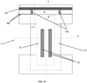
- Said rectangular patch extends along the transversal edge of the absorbent insert (4) and partially along the longitudinal edges of the absorbent insert (4) as illustrated in FIG. 10 .
- said patch (18) covers the portion of the absorbent insert (4) proximal to the front and/or back transversal edge, preferably the portion of the absorbent insert (4) proximal to the back transversal edge.
- the discrete layer or patch (18) in embodiments herein may be bonded, meaning joined or attached or associated, to the absorbent insert (4) by at least one bonding means (19).
- Bonding means comprise and are not limited to for example adhesive bonding and/or mechanical bonding and/or ultrasonic bonding.
- the discrete layer or patch (18) can be joined to the absorbent insert (4) by two or more bonding means.
- the bonding means comprises here adhesive bonding (19a) in an area arranged along the transversal edge of the absorbent insert (4) and mechanical bonding (19b) in an area arranged along the longitudinal edge of the portion of the absorbent insert (4) proximal to the front and/or back transversal edge, preferably the back transversal edge.
- the bonding means comprise only adhesive bonding (19a) arranged along the transversal and longitudinal edges of the portion of the absorbent insert (4) proximal to the front and/or back transversal edge. Arranging the bonding means at the transversal and longitudinal edges of the absorbent insert (4) enables to have a proper waist transversal barrier (5) and contain any exudate within the absorbent insert (4).
- the opening formed by the unattached, or un-joined portion is positioned closer, or at equal distance for the edges of the shortest sides, to a transversal centerline (x) than the joined portions of the perimeter of the patch.
- the bonded portion is represented by reference (19) and the unattached portion is represented by reference (23).
- the unattached portion (23) When looking at the absorbent article laid flat on a surface from above, the unattached portion (23) generally covers a portion of the absorbent insert (4), namely the portion proximal to the transversal edge of the absorbent insert (4). According to some embodiments, the unattached portion (23) can optionally further cover a portion of the absorbent core (8) as illustrated in FIG. 11B .
- the bonded or joined portion 19 can either cover a portion of the absorbent insert (4), namely the portion proximal to the transversal edge of the absorbent insert (4) only ( FIG. 10 ) or cover a portion of the absorbent insert (4), namely the portion proximal to the transversal edge of the absorbent insert (4) and a portion of the back panel (3) ( FIG.
- the patch or discrete layer 18 can be joined to the outer panel (3), namely to the inner nonwoven layer (9), and/or the patch or discrete layer 18 can be joined to absorbent insert (4).
- said barrier (5) comprises one or more of an elastic film and an elastic strand, and wherein the elastic film and/or strand(s) form an elastic area (EA) and wherein the elastic area is less than a patch area such that a substantially inelastic area (IA) is positioned outboard of the elastic area, preferably wherein the inelastic area comprises at least one of: an area free of elastic film and/or strand(s); and an area wherein the elastic film and/or strand(s) has been de-activated.
- Deactivation of elastic includes cutting or severing elastic for example using a knife roller combined to an anvil roller. Other methods of deactivation include and are not limited to melting, using heat and/or chemical agents, or any other means of providing stiffness e.g. glue in non-stretched state or addition of other stiffeners.
- At least a portion of the substantially inelastic area (IA) is joined to the absorbent insert (4) and/or panel(s) (2, 3).
- this allows for optimal anchoring.
- the un-joined portion of said perimeter comprises a further elastic material, preferably in the form of one or more elastic strands such as LYCRA ® .
- the elastic area (EA) comprises a plurality of wrinkles; and/or wherein the elastic area comprises a plurality of apertures.
- said least one nonwoven layer and elastic film and/or strands are joined by mechanical bonding, at a plurality of discrete bonding elements and wherein each said patch comprises a plurality of wrinkles having peaks and troughs formed on at least one of said nonwoven layer wherein said patch comprises an average of no more than two, preferably no more than one, wrinkles between two consecutive discrete bonding elements along a patch length extending substantially parallel to the transverse axis.
- the patch (18) comprises a wrinkle distribution of at least 1.1 wrinkles/mm, according to the method herein.
- the apertures are preferably formed at bonding sites within a bonding pattern formed by mechanical bonding for example.
- the openings are made by laser perforation or mechanical piercing such as by one or more needles and/or pins, and preferably wherein the discrete bonding elements are made by ultrasonic bonding preferably such that the nonwoven web(s) and film are melt-fused such to form an aperture at a center of each said discrete bonding elements, preferably wherein the openings are made by laser perforation.
- the manufacturing process herein may be configured to aperture the assembled laminate after assembly for example by inserting pins or needles through the laminate (preferably in combination with heat e.g. the pins or needles are heated for piercing the laminate).
- the nonwovens may be deformed, and protrusions may be created where the apertures are formed.
- Such protrusions may extend outward from one surface of the laminate.
- the surface of the resulting laminate that includes the protrusions protruding therefrom may feel relatively rough and thus can detract from other desirable features of the elastic laminate, such as softness.
- the at least portion of said absorbent insert (4) proximal to the front and/or back transversal edges thereof comprises one or more folds forming the transversal waist barrier(s) (5), preferably wherein said fold is substantially U-shaped or C-shaped.
- fold of the absorbent insert allows to form a liquid impermeable barrier to exudates, and particularly the U-shape or C-Shape (vs other shapes) allows to form a maximised pocket for exudate collection with the minimum use of material.
- the folded portion of said absorbent insert (4) is joined to the body-facing surface of the topsheet (6) at a pair of oppositely disposed extremities of the absorbent insert (4) along a portion of the left and right longitudinal edges thereof, generally wherein said oppositely disposed extremities are connected by a fold of said folded portion of said absorbent insert (4), such that a pocket is formed that acts as a barrier to exudates in both the longitudinal direction (i.e. substantially parallel to the longitudinal axis y) and the transverse direction (i.e. substantially parallel to the transverse axis x).
- the said extremities of the absorbent insert (4) may be joined by adhesive and/or mechanical bonding such as ultrasonic bonding, thermal bonding, and/or pressure bonding and the like.
- the absorbent insert (4) comprises a substantially liquid permeable topsheet (6), a substantially liquid impermeable backsheet (7), and an absorbent core (8) sandwiched therebetween, preferably wherein the absorbent core (8) is positioned inboard of the perimeter of said absorbent insert (4) when viewed in a planar direction (as generally depicted and illustrated in the figures herein and that typically corresponds to a plane formed by the x and y axis described and illustrated herein) such that the one or more folds are substantially free of absorbent material.
- a fold that is substantially free of absorbent material allows for a more flexible fold that can allow said barrier to better stand upright upon application of tension and yet limit piercing of the topsheet and/or backsheet that could arise if exerting a folding force in an area of the absorbent insert comprising SAP particles.
- the transversal barrier (5) is breathable and has a water vapor transmission rate (WVTR) of less than about 2300 g/m 2 x24hr at an elongation of about 0% and a water vapor transmission rate (WVTR) of more than about 2800 g/m 2 x24hr at an elongation of about 100%, according to the test method herein; preferably a water vapor transmission rate (WVTR) of less than about 2250 g/m 2 x24hr, preferably less than about 2150 g/m 2 x24hr, even more preferably from about 500 g/m 2 x24hr to about 2000 g/m 2 x24hr, at an elongation of about 0%; and a water vapor transmission rate (WVTR) of more than about 2850 g/m 2 x24hr, preferably more than about 2950 g/m 2 x24hr, more
- WVTR water vapor transmission rate
- the inner and outer nonwoven layers (9, 10) may be the same or different meaning that they may have the same or different properties selected from basis weight (in gsm) and composition.
- both the inner and outer nonwoven layers (9, 10) each comprise a spunbond nonwoven, typically comprising monocomponent fibers of polypropylene, and each have a basis weight of from 10 g/m 2 (gsm) to 30 g/m 2 (gsm), preferably from 12 g/m 2 (gsm) to 25 g/m 2 .
- the outer nonwoven layer (10) may have a basis weight that is higher than the inner nonwoven layer (9).
- barrier embodiments herein especially when the outer nonwoven layer is folded and/or extends over the absorbent insert; and/or when the transversal barrier is elasticised
- such arrangement provides for added mechanical integrity desirable for resistance to tear on elastification and/or added softness for the wearer on the front and/or back waist regions up to said barrier location.
- the elastic material (11), such as the plurality of elastic strands, is/are deactivated in an area of overlap of the absorbent insert (4) when viewed in a planar direction.
- the deactivation is preferably achieved by cutting of the elastic strands such as to render the deactivated region of the panel(s) (2, 3) substantially inelastic and regions neighbouring said deactivated region and comprising said elastic strands being elastic.
- the absorbent core (8) of the absorbent insert (4) is positioned within the deactivated region such that it substantially does not overlap the elastic strands (11).
- this allows for improved core integrity as risks of core collapse due to excessive tension from the stretched elastics when the article is worn is limited.
- the transversal waist barrier(s) (5) is positioned to overlap the deactivated region of the panel(s) (2, 3).
- this allows for improved fit of said barrier when the article is worn by a subject.
- transversal waist barrier(s) In addition or alternatively, more than 50%, preferably more than 60%, even more preferably from 65% to 95%, of a total transversal length (generally substantially parallel to the transversal axis x) of the transversal waist barrier(s) (5) overlaps the deactivated region of the panel(s) (2, 3). Especially when the transversal waist barrier(s) is elastic, this arrangement may advantageously not only improve core integrity but further avoid excessive tension build-up.
- the transversal waist barrier(s) (5) is elastic, preferably comprising an elastic material selected from the group consisting of an elastic film and one or more elastic strands.
- an elastic material selected from the group consisting of an elastic film and one or more elastic strands.
- the elastic strands in any of the embodiments herein may be strand-coated with adhesive prior to joining to one or more layers such as the inner and outer nonwoven layers (9, 10) to form elastic panels (2, 3) and/or the backsheet (7), outer cover (7'), and/or outer nonwoven layer (10) to form the elastic transversal waist barrier(s) (5).
- adhesive in the form of a plurality of stripes is applied such as by slot coating.
- the one or more elastic strands of the transversal waist barrier(s) (5) comprise at least one flat elastic (such as elastics having a cross-section with an aspect ratio of longest to smallest dimension of greater than 1, preferably greater than 1.5, even more preferably greater than 2), preferably in combination with at least one or at least two round elastics (such as elastics having a cross-section with an aspect ratio of longest to smallest dimension of about 1).
- flat elastics are generally more expensive, they are advantageous in providing better gasketing effects and comfort on the wearer's skin, by combining flat and normal/round elastics one can achieve the desired gasketing and comfort whist limiting the cost.
- flat elastic When one or more, preferably only one, flat elastic is used it is preferably positioned adjacent to an apex of the transversal waist barrier(s) (5) that may be closest to a transversal edge of the absorbent insert (4) and further round elastic(s) positioned further from said apex compared to the flat elastic(s).
- this allows for the flat elastic to be positioned at the closest contact position to the wearer with other elastics being inboard (or further away) therefrom hence contributing to the desired tensile strength yet permitting to lower the overall density/dtex of the flat elastic and hence also cost, with limited impact on performance.
- elastic strands When elastic strands are used, they may have a dtex in the range of from 350 to 1100, preferably from 400 to 1000, even more preferably from 450 to 900.
- the elastic strands of said panel(s) (2, 3) When elastic strands are used in all of the front and/or back panels (2, 3) and the transversal waist barrier(s) (5), the elastic strands of said panel(s) (2, 3) have a dtex that is equal to or greater than, preferably greater than, that of the elastic strand(s) of said transversal waist barrier(s) (5).
- the elastic strand(s) of said transversal waist barrier(s) (5) have a dtex that is from 40% to 85%, preferably from 45% to 75%, even more preferably from 50% to 70%, of the dtex of the elastic strands of said panel(s) (2, 3).
- this allows said barrier(s) to stand up and provide a gasketing effect close to the skin of the wearer without flattening or adding excessive resistance to stretch that would otherwise impact fit and comfort.
- the tension differential that results entails that a lower tension in said barrier(s) compared to the belt(s) is generated to a degree that upon stretching of the belt(s) said barrier(s) stand-up away from said belt(s).
- the front and back panels (2, 3) may each be divided into multiple zones spanning in the transverse direction and defined by its location from the distal edge to the proximal edge relative to the percentage of the seam length wherein the distal edge is considered 0% and the proximal edge is considered 100%.
- the multiple zones may be configured to provide different tensile stress, or different functions to the front and back panels (2, 3), respectively.
- one or more second elastic strands (12) are comprised directly or indirectly between the outer nonwoven layer (10) and the backsheet (7), preferably between a body-facing surface of the outer nonwoven layer (10) and a garment-facing surface of the backsheet (7).
- An example of an indirect elastic arrangement is the presence of an outer cover layer (7') as described herein (that would generally be interposed between the backsheet (7) and the one or more second elastic strands (12)), and an example of a direct elastic arrangement is the absence of an outer cover layer (7') as described herein.
- this arrangement allows for a simple yet effective elastification of said barrier(s) permitting optimal gasketing effects.
- the one or more second elastic strands (12) extends along the entire transversal length of the transversal waist barrier(s) (5) and beyond, preferably crossing the imaginary longitudinal axis (y) in a direction substantially parallel to the imaginary transverse axis (x).
- the one or more second elastic strands (12) extends from a first position substantially adjacent a seam edge of the outer nonwoven layer (10) to a second position substantially adjacent an opposite seam edge of the outer nonwoven layer (10) with the imaginary longitudinal axis (y) being positioned therebetween, more preferably wherein the one or more second elastic strands (12) extends from said first position to said second position and crosses and/or overlaps the entire transversal waist barrier(s) (5) generally along the imaginary transverse axis (x).
- this allows not only to form a standing barrier upon stretching but further aids better fit on the wearer's front and/or back waist.
- the absorbent core (8) comprises absorbent material selected from the group consisting of superabsorbent polymer particles and/or fibers; and cellulose fibers, preferably wherein said absorbent material is enclosed within a core wrap comprising top and bottom core wrap layers being a same nonwoven layer folded to sandwich the absorbent material therein or distinct nonwoven layers joined together to sandwich the absorbent material therein.
- the superabsorbent polymer particles and/or fibers may be comprised in an amount of greater than 50%wt, preferably greater than 60%wt, even more preferably greater than 70%wt, most preferably from 75% to 100%wt, by total weight of absorbent material.
- the back panel (3) is wider (generally in a direction substantially parallel to the longitudinal axis y) than the front panel (2) such that a length of the seams is substantially equal to a width (generally in a direction substantially parallel to the longitudinal axis y) of the front panel (2) and less than a width of the back panel (3); or wherein the front panel (2) is wider than the back panel (3) such that a length of the seams is substantially equal to a width of the back panel (3) and less than a width of the front panel (2).
- this may permit comfort as well as improved protection compared to symmetric arrangements.
- the backsheet (7) comprises a further outer cover layer (7') on a garment-facing surface thereof, preferably wherein said outer cover layer (7') comprising one or more nonwoven layers, and/or wherein the backsheet (7) comprises a further outer cover layer (7') that is shorter in the longitudinal direction (generally parallel to the longitudinal axis y) than the topsheet (6) and/or backsheet (7) such that at least a portion of an overlap length between the absorbent insert (4) and the panel (2, 3) is free of said outer cover layer (7') and preferably wherein the backsheet (7) is directly joined to, or is in contact with, the panel (2, 3) in said portion of an overlap length between the absorbent insert (4) and the panel (2, 3) free of said outer cover layer (7').
- this allows for improved softness in areas where needed and yet allow for material savings thus permitting both reduced cost and waste.
- the outer cover layer (7') is preferably different from the inner and/or outer nonwoven layers (9, 10) meaning that they may have different properties selected from basis weight (in gsm) and composition.
- the outer cover (7') comprises a spunbond nonwoven preferably comprising bicomponent fibers typically selected from the group consisting of polypropylene and polyethylene.
- the outer cover (7') preferably has a basis weight that is less than the basis weight of the inner and/or outer nonwoven layers (9, 10).
- the outer cover (7') may have a basis weight of from 8 g/m 2 (gsm) to 20 g/m 2 (gsm), preferably from 10 g/m 2 (gsm) to 15 g/m 2 .
- the outer cover provides for softness to the touch to the care giver yet, as selected, it limits stress build-up particularly in embodiments with reduced length in the longitudinal direction as described above. Indeed without wishing to be bound by theory, stress build-up in the transition region corresponding to the terminal edge of the outer cover may result in a higher risk of tearing in the absorbent insert to panel joint.
- the absorbent insert (4) is folded-over to form the waist barrier(s) (5) such that at least a portion of the topsheet (6) of the non-folded part of said insert (4) may come into contact with the folded part of said insert (4).
- this allows said barrier to overlap the topsheet so as to help guide the exudates therethrough and into the core once stopped by said barrier.
- the waist barrier(s) (5) extends from 5% to 50%, preferably from 10% to 40%, even more preferably from 15% to 30%, of the total folded length (TFL) of the outer nonwoven layer (10) along the longitudinal axis (y).
- this may allow formation of a sufficiently large pocket yet avoid excessive resizing of the absorbent insert that may add cost and waste.
- the substantially liquid impermeable film layer or backsheet (7) comprises indicia, preferably a coloured print, at a position corresponding to the transversal waist barrier (5); and/or wherein the one or more second elastic strands (12) are coloured; and/or wherein a garment facing surface of the outer nonwoven layer (10) is coloured; and/or wherein the transversal waist barrier (5) comprises indicia selected from a coloured print and coloured adhesive (preferably comprising one or more pigments).
- a coloured print and coloured adhesive preferably comprising one or more pigments
- the absorbent article further comprising a pair of longitudinally extending cuffs positioned along left and right longitudinal edges of the absorbent insert (4), and wherein the transversal waist barrier(s) (5) is positioned above said cuffs such that said barrier(s) (5) is closer to a wearer's skin than said cuffs; preferably wherein the cuffs are joined to a body-facing surface of the topsheet (6) and wherein each of said cuffs is folded and joined to itself on a body-facing surface thereof at a joining position (JP) corresponding to the transversal waist barrier(s) (5), preferably said joints or joining positions (JP) extending along a lengthwise portion of, and being substantially adjacent to, the left and/or right longitudinal edges of the absorbent insert (4).
- this reduces risk of leakage multidirectionally and prevents leakage to seep through between the transversal barrier and cuffs unlike when otherwise arranged.
- the transversal waist barrier (5) is an up-standing barrier generally arranged to block substantially liquid exudates from flowing therethrough.
- the liquid impermeable film layer is breathable and has a basis weight of less than 50 g/m 2 , preferably from 8 g/m 2 to 45 g/m 2 .
- the film may be elastic (or may comprise elastic material such as one or more elastic strands and/or elastic foam) and may comprise micro-openings sized to allow at least some water vapour to permeate therethrough.
- the film having a ratio of the MD load at break to the CD load at break of less than about 8, and a machine-direction notched trapezoidal tear strength of at least about 25 g.
- the liquid impermeable film layer is a discrete layer and generally applied in the form of a patch joined to said insert via suitable bonding techniques such as adhesive and/or mechanical bonding as described in more detail herein, it is preferably elastic.
- “Elastic,” “elastomeric,” and “elasticized/elasticised” herein generally mean the ability of a material to stretch by at least 100% without rupture or breakage at a given load, and upon release of the load the elastic material or component exhibits at least 70% recovery (i.e., has less than 30% set).
- the adhesive may be applied in a first joining zone or bonding zone and the mechanical bonding may be applied on a second joining zone, and preferably wherein the adhesive is continuously applied along the first joining zone at an area generally comprising substantially the entire transversal-waist-barrier-width (typically extending along an axis parallel to the transversal axis x, and generally adjacent the front and back transversal edges).
- the first and second joining zones may be proximal to each other (or adjacent) such that the majority, preferably substantially all, the area of adhesive is not overlapped by mechanical bonds.
- this allows for extra anchoring and breathability generally afforded by the mechanical bonding yet maintain an appropriate liquid seal to limit leakage through said barrier along the transversal edge of the absorbent insert.
- the impermeable film layer when present, may be discrete and joined to the absorbent insert (4) by at least one of adhesive and mechanical bonding such as ultrasonic bonding, heat bonding, pressure bonding, and the like; or may be an integral part of the absorbent insert (4) and may form barriers herein such as by folding a portion thereof as described in more detail hereinbelow.
- a portion of the absorbent insert proximal (typically adjacent) to the front and/or back transversal edges thereof may be folded onto itself and the fold (as described in embodiments herein) has a length (L) in a longitudinal direction running substantially parallel to a longitudinal axis (y), and wherein said insert (4) further comprises a pair of longitudinally extending cuffs positioned along left and right longitudinal edges thereof and joined thereto along a tack-down length (LT) extending from a position proximal (preferably adjacent) to at least the back transversal edge to a tack-down terminal position longitudinally displaced therefrom along said longitudinal axis (y), and wherein the tack-down length (LT) is less than or equal to about 2L, preferably said cuffs being joined to a body-facing surface of the topsheet (6).
- LT tack-down length
- the back and/or front transversal edge typically coincides with a terminal edge (TE) of the transversal waist barrier (5) forming a pocket opening.
- the transversal waist barrier (5) comprises one or more second elastic strands (12) positioned at a distance (d) from a terminal edge (TE) of the transversal waist barrier (5) forming a pocket opening, and wherein the distance between the elastic closest to said terminal edge is less than about 0.6L, preferably from 0.15L to 0.5L, even more preferably from 0.20 to 0.45L.
- this permits the transversal barrier to more easily stand-up and make a seal with the wearer's skin and preferably yet be sufficiently displaced from the terminal edge to minimize risk of elastic exposure to the skin of a wearer.
- the font and/or back panels (2, 3) are elastic and comprise an inner nonwoven layer (9), an outer nonwoven layer (10), and an elastic material (11) sandwiched therebetween, wherein the elastic material is selected from the group consisting of an elastic film and a plurality of elastic strands.
- the outer nonwoven layer (10) is wider than the inner nonwoven layer (9) (generally in a direction substantially parallel to the longitudinal axis y) and is folded over said inner nonwoven layer (9) such that it overlaps the portion of said absorbent insert (4) proximal to the front and/or back transversal edges and generally over a fold length (LF), preferably such that said outer nonwoven layer (10) overlaps both a portion of the backsheet (7) and a portion of the topsheet (6) that remains exposed from said one or more transversal waist barrier(s) (5) such to form a flange (F L ).
- this allows to cover the backsheet with nonwoven so that the backsheet does not come into contact with the skin of a wearer which could otherwise result in skin irritations and/or less comfort.
- the absorbent insert (4) may comprise a topsheet selected from an embossed nonwoven and/or a carded air-through-bonded nonwoven.
- the embossed nonwoven may comprise a spunbond nonwoven.
- the topographical surface of such particular nonwoven selection allows for the formation of peaks and slumps that acts to not only slow down the movement of liquid stool towards the transversal edges but further allows for containment ridges in areas overlapping said barrier(s) (5).
- the thickness of the absorbent insert (4) in an overlap area of said waist barrier (5) is less than the remaining thickness of said insert (4) (e.g. in areas other than the overlap area); and/or wherein the amount of absorbent material, if and/or when present, in in an overlap area of said waist barrier (5) is less (preferably at least 5%wt less, preferably at least 10%wt less, even more preferably at least 15%wt less, even more preferably at least 20%wt less) than the amount of absorbent material in other areas of said insert.
- said overlap area further overlapping with the front and/or back panels respectively.
- this allows for a larger pocket for exudate collection that synergistically cooperates with the overlapping front and/or back belts.
- a method for the manufacture of an absorbent article as described herein comprises the steps of:
- the above step are preferably in the above described sequential order.
- the method preferably comprises further additional steps selected from:
- a method for the manufacture of an absorbent article (1) may comprise the steps of:
- steps may be sequential in the order listed here-above or may be sequential but with the steps of joining said patch and joining said inserts being carried out substantially concurrently.
- the bonding means comprise applying a pattern of adhesive onto a discrete layer or patch (18) and/or applying a pattern of adhesive onto a portion of the absorbent insert (4) proximal to the front and/or back transversal edge said pattern of adhesive extending all along the transversal edges and partially along the longitudinal edges of the patch and/or absorbent insert (4) and applying said patch or discrete layer onto the top surface of the absorbent insert (4) at a portion of the absorbent insert being proximal to the front and/or back transversal edge to form transversal waist barrier(s) (5) or wherein the bonding means comprise mechanical bonding preferably ultrasonic bonding
- the method further comprises the steps of arranging an elastic material (12) over said discrete layer or patch (18) prior to step of folding an outer nonwoven layer (10) of the front and/or back panels (2, 3) over the folded absorbent insert (4) and patch or (18).
- the method further comprises the steps of folding an outer nonwoven layer (10) of the front and/or back panels (2, 3) over the absorbent insert (4) and discrete layer and joining said folded outer nonwoven layer (10) directly or indirectly to the absorbent insert (4) partially covered by the discrete layer.
- FIG. 1 Further methods herein for the manufacture of an absorbent article 1 may comprise the steps of: providing a front panel 2; providing a back panel 3; providing an absorbent insert 4 comprising front and back transversal edges and left and right longitudinal edges connecting the front and back transversal edges to form a perimeter thereof (and generally wherein the left and right longitudinal edges extend substantially along the longitudinal axis y and are oppositely disposed such that said longitudinal axis y extends therebetween, and the front and back transversal edges extend substantially along the transversal axis x, and typically substantially perpendicular to the longitudinal axis y, and are oppositely disposed such that said transverse axis x extends therebetween); folding a portion of said absorbent insert 4 proximal to the front and/or back transversal edges thereof onto itself, preferably the fold being in the shape of a substantially U-fold, to form transversal waist barrier(s) 5; joining said insert 4 to said front and back panels 2, 3 (generally such that at least a portion of the absorb
- front and back panels herein are made from continuous webs that are subsequently severed into discrete front and back panels typically after the step of joining the absorbent insert 4 to said front and back panels 2, 3.
- a method for the manufacture of an absorbent article 1 may comprise the steps of: providing an absorbent insert 4 comprising front and back transversal edges and left and right longitudinal edges connecting the front and back transversal edges to form a perimeter thereof; folding a portion of said absorbent insert 4 proximal to the front and/or back transversal edges thereof onto itself, preferably in the shape of a substantially U-fold, to form transversal waist barrier(s) 5; providing a front panel 2; providing a back panel 3; joining said insert 4 to said front and back panels 2, 3; and joining said front and back panels 2, 3 together along a pair of oppositely disposed side seams.
- said folding step is carried out by static folding where a static element, i.e. a stator, such as a stationary folding blade deflects a portion of said absorbent insert 4 proximal to the front and/or back transversal edges thereof onto itself.
- a static element i.e. a stator, such as a stationary folding blade deflects a portion of said absorbent insert 4 proximal to the front and/or back transversal edges thereof onto itself.
- the folding is step is preferably done by passive folding meaning that the folding is done with a moving element, i.e. the absorbent insert, being folded by an unmoving, or immobile or fixed element, e.g. a blade.
- Such folding is more cost efficient and more reproducible.
- the present disclosure encompasses embodiments where the folding step is carried out by dynamic folding, where a mobile element, e.g. an actuated folding blade, moves or is actuated to fold a portion of said absorbent insert 4 proximal to the front and/
- the method further comprises the steps of folding an outer nonwoven layer 10 of the front and/or back panels 2, 3 over the folded absorbent insert 4 and/or an inner nonwoven layer 9 and joining said folded outer nonwoven layer 10 directly or indirectly to the folded absorbent insert 4.
- this allows to prevent irritation or discomfort to the wearer as explained hereinabove whilst avoiding the use of added components/materials/elements whilst maintaining a simple and cost-effective production process.
- the method further comprises the step of arranging an elastic material 12 over the folded portion of the folded absorbent insert 4 prior to step of folding an outer nonwoven layer 10 of the front and/or back panels 2, 3 over the folded absorbent insert 4.
- the method further comprises the step of intermittently applying adhesive onto said portion of the absorbent insert proximal to the front and/or back transversal edges.
- the adhesive may be applied in joining zones or bonding zones.
- the joining or bonding zones comprises at least one area where the adhesive or mechanical bonding mean is applied.
- FIG. 11A which represents an absorbent article 1 prior to the folding step of the absorbent insert 4
- the adhesive is applied in a pattern 71 on one portion of said absorbent insert 4 proximal to the back transversal edge.
- FIG.11B illustrates the same absorbent article 1 after the folding step where the portion of the absorbent insert 4 proximal to the back transversal edge is folded thereof onto itself.
- the adhesive can also be applied in such pattern 71 to one portion of said absorbent insert 4 proximal to the front transversal edge.
- the adhesive can be applied in such pattern 71 to both portions of said absorbent insert 4 proximal to the front and back transversal edges.
- the pattern 71 of adhesive comprises the two portions or two areas of adhesive 70, meaning two joining zones, as described hereabove, meaning the area 70 at the transversal extremities of the transversal edge, or in other words, the corners of the absorbent insert 4, or also the portions where the back transversal edge and longitudinal edges of the absorbent insert 4 connect as illustrated in FIG. 11A .
- the pattern 71 of adhesive further comprises a further area 72 of adhesive extending transversally connecting the two areas 70 and an area free of adhesive 73, said area free of adhesive 73 is arranged between the transversal edge of the absorbent insert 4 and the further area 72 of adhesive with respect to the longitudinal direction (y) and arranged between the two areas 70 at the corners with respect to the transversal direction (x).
- the pattern 71 of adhesive comprise a U-shaped or C-shaped pattern with two areas 70 corresponding to the upper branches of the U, said areas 70 being connected by a further area 72 corresponding to the lower branch of the U.
- the pattern 71 of adhesive comprise a H-shaped pattern with two areas 70 corresponding to the side branches of the H, said areas 70 being connected by a further area 72 corresponding to the middle branch of the H.
- the pattern of adhesive can comprise two areas 70 at the corners and a further area 72 of adhesive which extend only partially along the transversal axis (x) and does not connect the two areas 70 while still defining an area free of adhesive 73 as described above.
- the further area 72 can comprise a gap free of adhesive.
- the pattern 71 of adhesive can comprise two areas 70 that are L shaped in facing relationship or in mirror relationship, said L-shaped areas being arranged at each corner.
- a transversal waist barrier 5 is defined with the area free of adhesive 73 not being joined to the absorbent insert 4 and therefore standing upright.
- said barrier(s) 5 herein form an opening, typically about a terminal edge of the folded outer nonwoven layer, of an exudate containing pocket wherein substantially the entire surface of the pocket being congruent with a topsheet 6 of the absorbent insert 4 comprises a liquid impermeable layer preferably being a film, more preferably an elastic film (generally according to the embodiments described herein).
- the angle defined by the fold and the waist barrier is more acute and can provide a transversal waist barrier 5 with more resistance to exudates.
- the method can comprise a mechanical bonding step where the portion of the absorbent insert 4 proximal to the back transversal edge is folded thereof onto itself and then mechanically bonded.
- the method comprises a step where the portion of the absorbent insert 4 proximal to the back transversal edge is glued to the absorbent insert 4 and/or a step where the portion of the absorbent insert 4 proximal to the back transversal edge is mechanically bonded to the absorbent insert 4.
- adhesive is intermittently applied to the portion of the absorbent insert 4 proximal to the back transversal edge, then said portion is folded thereof onto itself, then the folded portion is mechanically bonded, e.g. ultrasonic welding, to further secure the transversal waist barrier 5.
- the method for the manufacture of an absorbent article (1) comprises the steps of:
- the method for the manufacture of an absorbent article (1) comprising the steps of: providing a front panel (2); providing a back panel (3); providing an absorbent insert (4) comprising front and back transversal edges and left and right longitudinal edges connecting the front and back transversal edges to form a perimeter thereof; joining said insert (4) to said front and back panels (2, 3); applying a pattern of adhesive onto a discrete layer or patch preferably comprising liquid impermeable film, e.g.
- a patch of liquid impermeable film and/or applying a pattern of adhesive onto a portion of the absorbent insert (4) proximal to the front and/or back transversal edge said pattern of adhesive extending all along the transversal edges and partially along the longitudinal edges of the patch and/or absorbent insert (4); applying said discrete layer or patch (18) preferably comprising liquid impermeable film onto the top surface of the absorbent insert (4) at a portion of the absorbent insert being proximal to the front and/or back transversal edge to form transversal waist barrier(s) (5) and joining said front and back panels (2, 3) together along a pair of oppositely disposed side seams.
- this embodiment further comprises the step of arranging an elastic material (12) over said discrete layer or patch preferably comprising liquid impermeable film prior to step of folding an outer nonwoven layer (10) of the front and/or back panels (2, 3) over the folded absorbent insert (4) and patch.
- Said discrete layer or patch (18) preferably comprising liquid impermeable film is preferably in the form of a rectangular patch.
- Said rectangular patch extends along the transversal edge of the absorbent insert (4) and partially along the longitudinal edges of the absorbent insert (4) as illustrated in FIG. 10 .
- said patch (18) covers the portion of the absorbent insert (4) proximal to the front and/or back transversal edge, preferably the portion of the absorbent insert (4) proximal to the back transversal edge.
- the discrete layer or patch (18) preferably comprising liquid impermeable film is bonded, meaning joined or associated, to the absorbent insert (4) by at least one bonding means (19).
- Bonding means comprise and are not limited to for example adhesive bonding and/or mechanical bonding and/or ultrasonic bonding.
- the discrete layer or patch (18) can be joined to the absorbent insert (4) two or more bonding means.
- the bonding means comprises here adhesive bonding (19a) in an area arranged along the transversal edge of the absorbent insert (4) and mechanical bonding (19b) in an area arranged along the longitudinal edge of the portion of the absorbent insert (4) proximal to the front and/or back transversal edge, preferably the back transversal edge.
- the bonding means comprise only adhesive bonding (19a) arranged along the transversal and longitudinal edges of the portion of the absorbent insert (4) proximal to the front and/or back transversal edge. Arranging the bonding means at the transversal and longitudinal edges of the absorbent insert (4) enables to have a proper waist transversal barrier (5) and contain any exudate within the absorbent insert (4).
- the total surface area of the discrete layer or patch (18) preferably comprising liquid impermeable film is greater than the surface area of the bonding means (19), meaning that at least a portion of the total surface area of the discrete layer or patch (18) preferably comprising liquid impermeable film is not joined to the absorbent insert.
- the bonding means extend over a surface area of the discrete layer or patch (18) preferably comprising liquid impermeable film that is lesser than the total surface area of the discrete layer or patch (18) preferably comprising liquid impermeable film.
- the adhesive (19a) can be applied in a pattern, such as in a U-shaped or C-shaped pattern extending along the transversal and longitudinal edges of the portion of the absorbent insert (4) proximal to the front and/or back transversal edge.
- a pattern can optionally comprise notches 19c to save on raw material.
- An apparatus 20 may be used to manufacture an absorbent article 1 as described herein and following a method disclosed herein.
- Figure 5 illustrates one possible embodiment for an apparatus 20 for manufacturing such absorbent articles 1.
- the apparatus 20 extends in a machine direction MD, a cross-direction CD and a vertical direction Z.
- the machine direction MD corresponds to the direction of travel of the webs, elastic materials or any components of the absorbent articles 1 being manufactured
- the cross-direction CD is a direction perpendicular to the machine direction MD
- the vertical direction Z correspond to the height and is also a direction perpendicular to both the machine direction MD and the cross-direction CD.
- the machine direction MD is the flow direction of an absorbent article and its components being assembled in the process line, e.g. the machine direction MD is the direction in which the absorbent insert 4 is conveyed.
- upstream and "downstream” as used herein are with respect to the machine direction MD.
- coordinate system using longitudinal and transversal axis pertains to the absorbent article 1 alone e.g. when laid flat on a surface
- coordinate system using machine, cross and vertical directions pertains to the apparatus for manufacturing absorbent article 1 with the absorbent articles 1 and their components being conveyed.
- an absorbent insert 4 may be provided.
- the absorbent insert 4, assembled beforehand, may be transferred by a transfer device 22, a unit 22 comprising a plurality of transfer heads 24 arranged on a support wheel 26 with both the support wheel 26 and the transfer heads 24 being configured to respectively rotate around a respective axis.
- the transfer device 22 is generally an apparatus that is configured to turn and repitch the discrete absorbent inserts 4, turn the discrete absorbent inserts 4, or merely transfer the discrete absorbent inserts 4 between a pick-up location and a drop-off location.
- the transfer device 22, as illustrated in FIG. 5 comprises a frame 26, here a support wheel 26, defining a rotation axis and a plurality of transfer heads 24 associated to said frame 26.
- the transfer heads 24 are configured to circumnavigate about the rotation axis in an orbit. As illustrated in FIG. 5 , the support wheel 26 rotates around an axis parallel to the cross-direction CD and the transfer heads 24 circumnavigate about this rotation axis in an orbit. The orbit passes through the pick-up location and the drop-off location.
- the transfer device 22 turns the discrete absorbent inserts 4 in any suitable angle. For example, as illustrated in FIG. 5 , the transfer device 22 turns the discrete absorbent inserts 4 about 90 degrees. The discrete absorbent inserts 4 are turned by the transfer heads 24 turning.
- a transfer head 24 may pick up a discrete absorbent insert 4 in a pick-up location, turn 90 degrees about an axis perpendicular to the rotation axis of the frame, e.g. about the vertical direction Z, drop off the discrete absorbent insert 4 in a drop-off location, and the turn back to its original position (either in the same direction or an opposite direction) before orbiting back through the pick-up location.
- the transfer device 22 transfers an absorbent insert 4 extending in the machine direction (MD) and rotates it so that said absorbent insert 4 extends in the cross direction (CD).
- the absorbent insert 4 may be deposited onto a first conveying device 28, e.g. a conveyor belt 28, and/or a rotating drum 30. As illustrated in FIG. 5 , the absorbent insert 4 is deposited onto a rotating drum 30, but said insert 4 can be directly deposited onto a first conveyor belt 28.
- the first conveyor belt 28 and/or rotating drum 30 is/are associated with a negative pressure device such that the absorbent insert 4 when deposited onto the belt 28 and/or drum 30 is sucked onto the first conveyor belt 28 and/or rotating drum 30 and is maintained onto said conveyor belt 28 and/or rotating drum 30 by vacuum.
- the first conveyor belt 28 and/or rotating drum 30 comprises vacuum holes on its outer surface, meaning a foraminous outer surface, and the absorbent insert 4 is deposited onto said outer surface.
- the absorbent insert 4 is maintained on the foraminous drum 30 and/or foraminous first conveyor belt 28 by the negative air-pressure generated by the suction. As illustrated in FIG. 5 , the absorbent insert 4 is first deposited onto the rotating drum 30 and then transferred to the first conveyor belt 28, the absorbent insert 4 is then conveyed by the first conveyor belt 28 in the machine direction MD.
- adhesive is applied intermittently on at least one transversal edges, namely the adhesive is applied intermittently on a portion of said absorbent insert 4 proximal to the front and/or back transversal edges, meaning on the portion described hereabove to be folded.
- the adhesive is applied intermittently on at least one edge arranged at one end of the absorbent insert 4 with respect to the cross-direction CD as illustrated in figure 8 .
- the adhesive can be applied intermittently on one portion of said absorbent insert 4 proximal to the back transversal edges.
- the adhesive can be applied intermittently to one portion of said absorbent insert 4 proximal to the front transversal edges.
- the adhesive can be applied intermittently to both portions of said absorbent insert 4 proximal to the front and back transversal edges.
- the adhesive is applied intermittently such that the central area of said portion(s) proximal to the transversal edge(s) is not glued.
- the adhesive is applied on both portions 70 arranged at the corners of a transversal edge, but not in between said corners 70 as illustrated in FIG.4 .
- the adhesive is applied in the portion 70 located at the corner of the back transversal edge but is not applied on the portion where the absorbent core 8 extends, meaning when the back transversal edge and the absorbent core are transposed on a same machine direction axis, the adhesive applied is present at the corners but not where the absorbent core 8 extends.
- the adhesive is applied intermittently on one transversal edge only, preferably the back transversal edge.
- the adhesive is applied intermittently on both transversal edges.
- the adhesive can also be applied continuously in an adhesive pattern 71 as described above, for example in a U-shaped or a C-shaped or a H-shaped pattern.
- the adhesive may be applied by a glue dispensing device 32.
- a glue dispensing device 32 Such application of adhesive may be by various processes such as slot coating, spray coating and other topical applications using a pneumatic, piezo or electromagnetic actuator.
- the glue dispensing device 32 comprises at least one nozzle, each nozzle, for instance, may comprise a slot coating device or several exit ports and an adhesive flow control device such as electromagnetic valve, e.g. a solenoid valve.
- the absorbent insert 4 may then be conveyed, or transported, by the first conveyor belt 28 to a folding unit 34.
- the folding unit 34 comprises a folding blade 36 that is curved ( FIG. 6 , 9 ) and that can be associated with a support plate 38 as illustrated in FIG. 6 .
- the folding blade 36, or curved blade 36 comprises a blade with a curvature said curvature spanning over an angle from 0° to at least 200°.
- the curved blade comprises a concave portion, said concave portion varying along the machine direction and extending over an angle A° of at least 180°, preferably at least 250°, more preferably at least 300°, meaning angle A° is preferably a reflex angle as illustrated in FIG. 9 .
- the folding blade 36 comprises a curve blade 36, said curved blade 36 defines an angle A° that evolves along the machine direction MD, meaning that for a given point in the machine direction MD, the folding blade 36 extends in the vertical and cross directions Z,CD as illustrated in FIG. 9 , the two extremities of said blade 36 defining an angle A°, or folding angle A°, since the folding wall, meaning the wall used for folding the absorbent insert 4, of the blade is curved.
- the angle A° defined by the two extremities of the blade 36 is small, e.g. between 0° and 10°.
- the angle A° increases along the machine direction MD and is greater than 180° at the downstream portion of the folding blade 36.
- the support plate 38 is fixed, or removably associated to the folding blade 36. Having a blade 36 with a folding angle A° of 180° is sufficient to fold the absorbent insert 4 onto itself but it can lead to having wrinkles or a gap in the fold. Having a blade 36 with a folding angle A° of 250° or more enables to have a smoother fold and reduces the risks of wrinkles or a gap in the fold.
- the apparatus 20 can comprise a depositing unit, for example a liquid impermeable film layer depositing unit, or a patch depositing unit or a patch applying unit where a plurality of liquid retarding layers in the form of a patch or a discrete layer preferably of liquid impermeable film applied in the form of a patch is joined to said absorbent insert (4) via suitable bonding techniques such as adhesive and/or mechanical bonding as described hereabove.
- the apparatus comprises a bonding unit to join the patch 18 to the absorbent insert (4) and/or to the inner nonwoven layer (9), more generally to the back and/or front panel (3), to form a transversal barrier.
- the patch depositing unit and the bonding unit as sequential, in the sense that if the bonding means correspond to adhesive bonding, either the absorbent insert and/or the patch (18) pass first through the bonding unit first and adhesive is applied on the absorbent insert and/or the patch (18) and then through the patch depositing unit, alternatively, if the bonding means correspond to mechanical bonding the absorbent insert (4) passes through the patch depositing unit first and then through the bonding unit.
- the bonding means correspond to adhesive bonding
- the absorbent insert (4) passes through the patch depositing unit first and then through the bonding unit.
- the folding unit 34 can further comprise a pressing blade 40 arranged at a distance d from the curved blade 36 with respect to the cross-direction CD and/or vertical direction Z. In other words, there is a gap between the curved blade 36 and the pressing blade 40 in the cross-direction CD and/or vertical direction Z.
- the pressing blade 40 presses vertically against the absorbent insert 4 and maintain said absorbent insert 4 in place, at least vertically.
- the combination of the curved blade 36 folding the portion of the absorbent insert 4 proximal to the front and/or back transversal edge, and the pressing blade 40 pushing the absorbent insert 4 at least vertically, ensures a proper folding of the portion of the absorbent insert 4 proximal to the front and/or back transversal edges thereof onto itself, in order words a proper folding of the portion of the absorbent insert 4 proximal to the front and/or back transversal edge to form a transversal barrier 5 as described herein.
- the folding blade 36 deviates the portion of the absorbent insert 4 proximal to the front and/or back transversal edge in the cross direction CD and in the vertical direction Z and the pressing blade 40 deviates a portion of the absorbent insert 4, which is more distal to the transversal edge than said portion of the absorbent insert 4 proximal to the transversal edge e.g. in between said portion of the absorbent insert 4 proximal to the front and/or back transversal edge and the center of absorbent core 8, in the vertical direction Z.
- the pressing blade 40 at least maintains the absorbent insert 4 in place while the folding blade 36 is folding the portion of the absorbent insert 4 proximal to the transversal edge.
- the folding blade 36 alone can suffice to fold the portion of the absorbent insert 4 proximal to the front and/or back transversal edge, and adding a pressing blade 40 further improves the folding.
- the folding blade 36 ensures a folding preferably in the shape of a substantially U-fold, to form transversal waist barrier(s) 5. In the embodiment described above where adhesive is applied intermittently at the corners 70, then only the corners 70 of the portion of the absorbent insert 4 proximal to the front and/or back transversal edges are folded and glued thereof onto itself.
- the pressing blade 40 is preferably shorter in length, with respect to the machine direction MD, than the folding blade 36 so that when the curved blade 36 is folding the portion of the absorbent insert 4 proximal to the front and/or back transversal edge, namely once said portion has been folded by an angle of more than 180°, it folds thereof onto itself, meaning onto the upper surface of the absorbent insert 4, i.e. the topsheet 6.
- the pressing blade 40 can comprise a sloped portion 42 at the upstream portion of the pressing blade 40 with respect to the machine direction MD as illustrated in FIG. 7 .
- the slope portion 42 extends diagonally downward while extending downstream for holding down the absorbent insert 4 and improving the folding as described hereabove.
- the absorbent insert 4 can be conveyed toward one or more pressure roller(s) 46 which is arranged to press the folded portion, meaning the transversal waist barrier(s) 5, thereby securing the fold and eventually securing the glued and/or welded portions together.
- the partially folded absorbent insert 4 and front and back panels 2,3 may then be guided, for example by a second conveying device 58, such as a conveyor belt, to an elastic depositing unit or station, where a second elastic material 12, e.g. one or more elastic strands 12, is deposited onto the backsheet 7 or the outer cover 7' of the absorbent insert 4 at the region that has been folded over.
- a second elastic material 12 e.g. one or more elastic strands 12
- the elastic strand(s) 12 is typically beforehand coated with adhesive by an adhesive dispensing unit 50 such that when the elastic strand(s) 12 is applied on the backsheet 7 or outer cover 7' on the portion of the absorbent insert 4 that has been folded thereof onto itself, it remains in place.
- the adhesive is preferably continuously applied on the elastic strand(s) 12.
- the elastic strands 12 in any of the embodiments herein may be strand-coated with adhesive prior to joining to one or more layers such as the inner and outer nonwoven layers 9, 10 to form elastic panels 2, 3 and/or the backsheet 7, outer cover 7' and/or outer nonwoven layer 10 to form the elastic transversal waist barrier(s) 5.
- the elastic strand(s) 12 can be applied on the patch or discrete layer (18).
- the elastic material 12 e.g. the elastic strand(s) 12, is arranged such that said elastic material 12 is sandwiched between the absorbent insert 4 and the outer nonwoven layer 10.
- the absorbent insert 4 as described herein comprises a backsheet 7 and eventually an outer cover 7' on the garment facing surface of the absorbent core 8.
- the present disclosure encompasses embodiments where the elastic material 12 is sandwiched between the backsheet 7 and the outer nonwoven layer 10, embodiments where the elastic material 12 is sandwiched between the outer cover 7' and the outer nonwoven layer 10 or even embodiments where the elastic material 12 is sandwiched between the backsheet 7 and outer cover 7' and the outer nonwoven layer 10 e.g. in cases where the outer cover 7' is transversally shorter than the backsheet 7.
- the elastic material 12 is directly or indirectly joined to the backsheet 7, preferably by adhesive, and sandwiched between the backsheet 7 and/or outer cover 7' and the outer nonwoven layer 10.
- the outer nonwoven layer 10 may then be folded over the elastic strand 12, backsheet 7, outer cover 7' and/or the transversal elastic barrier 5 and by a second folding apparatus 64, in order to form the absorbent article 1 as illustrated in FIG. 3 .
- the apparatus 20 can further comprise an additional adhesive dispensing device 66 to apply adhesive on the portion of the front and/or back panels 2,3 to be folded.
- the apparatus 20 can further comprise a pressure roller 52 to apply pressure on the transversal edges of the front and/or rear panels 2,3 and ensure the structural integrity of the chassis.
- the outer nonwoven layer 10 is folded over the absorbent insert and/or thereof onto itself by the second folding apparatus 64 at the front and back panels 2,3 and the additional adhesive dispensing device 66 applies adhesive on a portion of the absorbent insert 4 proximal to the transversal edges of the front and back panels 2,3.
- the second folding apparatus 64 comprises a roller 65 that is arranged to cover a portion of the front and/or back panels 2,3, namely the roller is arranged at a distance from the transversal edge of the front and/or back panel 2,3 so that said roller deviates vertically said portion of the front and/or back panels 2,3, the transversal edge of the front and/or back panel which is not deviated by the roller naturally folds upward.
- the folding apparatus 64 can further comprise a railing 68 oriented diagonally with respect to the cross-direction CD toward the center of absorbent insert 4 to guide and facilitate the folding of the non-deviated portion of the outer nonwoven layer 10, i.e. the transversal edge of the front and/or back panel 2,3 onto the absorbent insert 4, namely onto the transversal barrier 5, backsheet 7 and/or outer cover 7'.
- a railing 68 oriented diagonally with respect to the cross-direction CD toward the center of absorbent insert 4 to guide and facilitate the folding of the non-deviated portion of the outer nonwoven layer 10, i.e. the transversal edge of the front and/or back panel 2,3 onto the absorbent insert 4, namely onto the transversal barrier 5, backsheet 7 and/or outer cover 7'.
- the belt meaning the front and back panels 2,3 may then be cut in the cross-direction CD into individual pieces, each individual piece comprising an absorbent insert 4 with a front and back panel 2,3. Each individual piece is then folded to bring the front and back panels 2,3 in proximity of one another and then associated in side seams to form an individual absorbent article 1 with a transversal barrier 5.
- the front and back panels 2,3 are joined, or associated, by bonding said panels 2,3 together at a bonding unit.
- the bonding unit can be selected from and not limited to an adhesive dispensing device, an ultrasonic device or a welding device.
- the front and back panel 2,3 can be joined first and then cut in the cross direction into individual pieces.
- the folding blade 36 comprises an extension 56 as illustrated in FIG. 9 where the extension 56 extends beyond the curvature of the blade 36 to ensure that the transversal edge is well folded thereof onto itself.
- the first conveyor belt 28 comprises a foraminous portion arranged at the central portion 60 of the first conveyor belt 28 with respect to the cross-direction CD as illustrated in FIG. 8 .
- Such arrangement ensure that the absorbent insert 4 is well fastened in the central portion 60, meaning in the crotch region of the absorbent insert 4, and is loosely secured at the at least one portion of the absorbent insert 4 proximal to the transversal edge.
- Such arrangement ensures that the folding blade 36 does not meet any resistance and that the portion of the absorbent insert 4 proximal to the transversal edge can be folded more easily. In other words, the vacuum should not impede the folding at the one or both cross direction extremities.
- the first conveyor belt 28 can also comprise a portion blowing out air at one cross direction extremity, the extremity proximal to the folding unit 34, to favor the lifting and thus folding of the portion of said absorbent insert 4 proximal to the front and/or back transversal edge.
- the folding unit 34 comprises an adjustable mechanism 62 to adjust the distance between the pressing blade 40 and the folding blade 36.
- adjustable mechanism comprises for example a plate with notches and screws enabling the sliding of the plate between the notches and adapt the distance with respect to the cross direction and/or vertical direction.
- the two webs of front and back panels can be conveyed at same speed or at different speed. If the two webs of front and back panels are conveyed at same speed, front and back panels will have the same lengths with respect to the transversal direction or machine direction and the side seams will be arranged at the sides of the wearer. If the two webs of front and back panels are conveyed at different speed, e.g. the web of back panel is conveyed faster than the web of front panel then the back panel will be longer than the front panel and the side seams will be more toward the front at the sides of the wearer.
- the folding unit 34 comprises two folding blades 36 each with eventually with a pressing blade 40, one arranged at each transversal edge of the absorbent insert 4, meaning one arranged at each end of the first conveyor belt 28 with respect to the cross-direction CD.
- the two folding blades 36 are substantially identical in dimensions and shape and are preferably arranged in facing relationship or in mirror relationship, meaning at the same area with respect to the machine direction MD.
- Such arrangement enables to balance the force exerted onto the absorbent insert 4 and optionally to remove the pressing blade(s) 40.
- the rest of the process is arranged accordingly, namely an elastic thread(s) 12 is arranged between the absorbent insert 4 and the front panel which is folded onto the elastic thread(s) 12.
- Such arrangement also enables to have a transversal waist barrier 5 in the front and in the back.
- the elastic material 11 sandwiched between the inner nonwoven layer 9 and the outer nonwoven layer 10 and the elastics strands 12 are different.
- the elastics 11,12 can differ in cross-sectional shapes, e.g. round or flat, in dtex, in composition and/or in color.
- said elastic material 11 and elastic strands 12 can the same material.
- the wrinkle distribution herein is determined by the following method.
- the number of wrinkles is counted over a length of 10mm along the panel length (L) with the laminate in relaxed state (i.e. without applying an extension force between ends thereof, preferably taken at its "unused” state wherein "unused” herein means without the panel ever having been previously stretched since manufacture).
- the total number of wrinkles is then divided by 10 in order to provide the number of wrinkles per unit length.
- a total of 4 random locations within the elastic region (20) of the laminate may be measured accordingly and an average is calculated for each sample.
- the above procedure is typically repeated for at least 4 samples of side panels and an average is calculated to provide the wrinkle distribution in wrinkles/mm as referred to herein.
- the specimen is cut with a dimension of 10 mm in the intended stretch direction of the ear X 25.4 mm in the direction perpendicular to the intended stretch direction of the ear.
- a specimen is collected from either an inelastic region or from an elastic region.
- a computer data system records the force exerted on the sample during the test as a function of applied strain. From the resulting data generated, the following quantities are reported:
- test samples are clamped to a tensile testing machine (such as an Instron 5543 or similar) and stretched at a cross-head speed of 300mm/min at the desired elongation (such as 0%; 20%; 40%; 60%; 80%; 100%; 120%; and 140% elongations).
- a test sample having a length of 40mm at 0% elongation is stretched to 48mm length at 20% elongation; 56mm length at 40% elongation; 64mm length at 60% elongation; 72mm length at 80% elongation; 80mm length at 100% elongation; 88mm length at 120% elongation; 96mm length at 140% elongation; and so on.
- the stretched test sample is then affixed to a self-adhesive sample card with an open area of 2.5cm2 which is to be covered by the specimen that is subsequently tested according to the WVTR method described in the above referenced standard.
- the Seepage is defined as a leakage fraction of artificial liquid exudates (saline solution composition described in the following sections for use in the test procedure herein) that is expelled beyond and/or through the transversal waist barrier or pocket of the absorbent article.
- An absorbent article in the pant form i.e. the type of absorbent articles to which the present invention generally refers
- the width of the back elastic belt is measured by applying a weight of 1.000 kg across the side edges formed along the previously cut open side seams of the back elastic belt.
- One of the side edges of the back elastic belt is clamped centered on the last centimeter of the side edge of the back elastic belt in a flat jaw 5 cm wide fixture with 1cm clamping depth. It is hung vertically and a 1.000kg weight is attached to an identical clamp that is provided the same manner and position on the other side edge of the back elastic belt and the weight is slowly released manually.
- the back elastic belt width is measured from clamp to clamp and 2cm are added to the result. The result is rounded to the next cm.
- the width of the front elastic belt is determined in the same manner as the width of the back elastic belt.
- the same procedure as described above is used for measuring the length of the absorbent article by applying a weight of 0.300kg.
- the absorbent article is clamped across the longitudinal centerline of the absorbent article on the last centimeter of the back waist edge in a flat jaw 15 cm wide fixture (centered on the longitudinal centerline) with 1cm clamping depth. It is hung vertically and a 0.300kg weight is attached to an identical clamp that is provided the same manner and position on the front waist edge of the absorbent article and the weight is slowly released manually.
- the absorbent article length is then measured after 30 second from clamp to clamp and 2cm are added to the result. The result is rounded to the next cm.
- An inclined surface is made from acrylic plates so that a laying face corresponding to the face onto which an article is to be placed, is at an angle of 25° from a horizontal plane (e.g. a table onto which the inclined surface is placed).
- the laying face should be sized so as to accommodate thereon an absorbent article in laid-flat sate (i.e. stretched/extended to the above explained measured width and length dimensions).
- the whole laying face of the plate may be conveniently coated with hook material to nicely hold the absorbent article in laid-flat sate by interaction of said hooks with nonwoven layers of the article or alternatively tapes may be used to hold the article in position.
- the absorbent article is laid down in a flat planar configuration onto the inclined surface, on the laying surface of the inclined surface, with the topsheet facing upwards and the back sheet taut, extended to the before measured width and length dimensions and fixed with tape stripes or joined to the hook surface of the plate as explained above.
- the article being positioned such that the waist barrier is located closest to the horizontal plane with the opening thereof facing away from said horizontal plane (i.e. such that it is located towards the bottom of the inclined slope and the opening facing upwards so that liquid can be poured/added therein with the aid of gravity).
- a line 5mm above the terminal transversal edge (TT) of the pocket and running parallel therewith should correspond to an upper edge of a filter paper when placed according to the below explained procedure.
- saline solution composition description below
- a pipette preferably by applying it from left to right with a constant movement so that the liquid is evenly distributed in the pocket
- Liquid that leaks through the barrier is collected by the filter paper.
- the filter paper is then weighed and the original (dry) weight is subtracted. This calculation a rewet value for the filter paper in grams (g).
- the Seepage Index % rewet value g / total saline solution added g * 100 3 to 5 replicates on identical absorbent articles are tested. The reported Seepage Index (%) is reported as the average of the replicates and is calculated to within +/- 0.1%.
- Saline solution preparation 9g of NaCl are dissolved in 1000ml of H 2 O.
Landscapes
- Health & Medical Sciences (AREA)
- Epidemiology (AREA)
- Engineering & Computer Science (AREA)
- Biomedical Technology (AREA)
- Heart & Thoracic Surgery (AREA)
- Vascular Medicine (AREA)
- Life Sciences & Earth Sciences (AREA)
- Animal Behavior & Ethology (AREA)
- General Health & Medical Sciences (AREA)
- Public Health (AREA)
- Veterinary Medicine (AREA)
- Absorbent Articles And Supports Therefor (AREA)
- Orthopedics, Nursing, And Contraception (AREA)
Claims (19)
- Absorbierender Artikel (1) für Körperhygiene, vorzugsweise eine Einwegunterhose, umfassend:- ein im Wesentlichen sich quer erstreckendes vorderes Feld (2);- ein im Wesentlichen sich quer erstreckendes hinteres Feld (3); und- eine sich im Wesentlichen in Längsrichtung erstreckende absorbierende Einlage(4), die mit jedem des vorderen und des hinteren Felds (2, 3) gefügt ist, die absorbierende Einlage (4) umfassend vordere und hintere Querkanten sowie linke und rechte Längskanten, die die vorderen und hinteren Querkanten verbinden, um einen Umfang davon auszubilden; und wobei die Einlage (4) einen absorbierenden Kern (8) umfasst;wobei das vordere und das hintere Feld (2, 3) zusammengefügt sind, um ein Paar von Seitennähten auszubilden, und dadurch gekennzeichnet, dass der Artikel eine quer verlaufende Taillenbarriere (5) proximal zu den vorderen und/oder hinteren Querkanten der absorbierenden Einlage (4) umfasst, wobei die Barriere (5) eine Vielzahl von flüssigkeitsbremsenden Schichten umfasst, wobei die Vielzahl von flüssigkeitsbremsenden Schichten mindestens zwei Schichten, die aus der Gruppe ausgewählt sind, bestehend aus hydrophoben Vliesstoffen und im Wesentlichen flüssigkeitsundurchlässigen Folien, und dass mindestens ein Großteil der Taillenbarriere (5) mindestens zwei der Vielzahl von flüssigkeitsbremsenden Schichten umfasst, und wobei die mindestens zwei der Vielzahl von flüssigkeitsbremsenden Schichten an einer oder mehreren Stellen nicht gefügt sind, sodass die Schichten an der/den Stelle(n) durch einen Spalt (G) voneinander getrennt sind, und vorzugsweise wobei die eine oder die mehreren Stellen zusammen einem Großteil einer Gesamtoberfläche der Taillenbarriere (5) entsprechen.
- Absorbierender Artikel nach Anspruch 1, wobei die Taillenbarriere (5) mindestens zwei hydrophobe Vliesstoffe, die durch Klebstoff mit Unterbrechungen zusammengefügt sind, umfasst, vorzugsweise durch einen oder mehrere elastische Stränge, die mit Klebstoff strangbeschichtet und dazwischen angeordnet sind.
- Absorbierender Artikel nach einem der vorstehenden Ansprüche, wobei der Artikel einen Sickerindex von weniger als 35 %, vorzugsweise weniger als 30 %, vorzugsweise weniger als 25 %, mehr bevorzugt weniger als 20 %, noch mehr bevorzugt weniger als 10 %, noch mehr bevorzugt von 0 % bis 5 %, gemäß dem Sickerindexverfahren hierin, aufweist.
- Absorbierender Artikel nach einem der vorstehenden Ansprüche, wobei die hydrophoben Vliesstoffe synthetische Fasern umfassen, vorzugsweise daraus bestehen; vorzugsweise wobei die Fasern ein Material, ausgewählt aus Polypropylen oder Derivaten davon, Polyethylen oder Derivaten davon, Polymilchsäure oder Derivaten davon, Polymilch-co-Glycolsäure oder Derivaten davon, Polyhydroxyalkanoaten oder Derivaten davon und Gemischen davon, umfassen.
- Absorbierender Artikel nach einem der vorstehenden Ansprüche, wobei das vordere und/oder das hintere Feld (2, 3) eine Vielzahl von elastischen Strängen (11), die zwischen zwei oder mehr hydrophoben Vliesstoffschichten angeordnet sind, umfassen, die Vliesstoffschichten umfassend mindestens einen inneren Vliesstoff (NW1) und einen äußeres Vliesstoff (NW2), die im Wesentlichen kongruent zueinander sind, um ein Laminat (PL) für das vordere/und oder das hintere Feld auszubilden; und wobei das Laminat (PL) für das vordere/und oder das hintere Feld auf sich selbst gefaltet ist, um die Barriere (5) auszubilden, und derart, dass sowohl der innere als auch der äußere Vliesstoff (NW1, NW2) an einer oder mehreren Positionen gefaltet sind.
- Absorbierender Artikel nach Anspruch 5, wobei mindestens der innere Vliesstoff (NW1) ein mehrschichtiger Vliesstoff ist, umfassend mindestens zwei, vorzugsweise mindestens drei Schichten, die aus einem Spinnvliesstoff und einem Schmelzblasvliesstoff ausgewählt sind, wobei der Vliesstoff mehr bevorzugt aus einem spinngebundenen-schmelzgeblasenen Vliesstoff, einem spinngebundenen-schmelzgeblasenen-spinngebundenen Vliesstoff und einem spinngebundenen-schmelzgeblasenen-schmelzgeblasenen-spinngebundenen Vliesstoff ausgewählt ist.
- Absorbierender Artikel nach einem der Ansprüche 5 bis 6, wobei der äußere Vliesstoff (NW2) ein Vliesstoff ist, der gleich oder verschieden von dem inneren Vliesstoff (NW1) ist, der äußere Vliesstoff (NW2) vorzugsweise umfassend, mehr bevorzugt bestehend aus, eine(r) oder mehreren Spinnvliesstoffschichten.
- Absorbierender Artikel nach einem der Ansprüche 5 bis 7, wobei das vordere und/oder das hintere Feld (2, 3) eine Bauchaussparung (TP) umfassen, die frei von den elastischen Strängen ist oder umfassend elastische Stränge, die durch Deaktivierung unelastisch gemacht wurden, und wobei die Barriere (5) die Bauchaussparung (TP) überlappt, vorzugsweise die gesamte Breite der Bauchaussparung (TP) entlang einer Achse, parallel zu der Quermittellinie (x) überlappt.
- Absorbierender Artikel nach Anspruch 8, wobei die Bauchaussparung (TP) eine Breite, die sich entlang einer Achse parallel zu der Quermittellinie (x) erstreckt, aufweist, und wobei die Breite mehr als 60 %, vorzugsweise mehr als 65 %, mehr bevorzugt 70 % bis 180 %, noch mehr bevorzugt 75 % bis 150 %, einer Gesamtbreite der absorbierenden Einlage (4) beträgt.
- Absorbierender Artikel nach einem der Ansprüche 5 bis 9, wobei das vordere und/oder das hintere Feld (2, 3) einen ersten elastischen Bereich (ER1) und einen zweiten elastischen Bereich (ER2) umfassen, wobei der erste und der zweite elastische Bereich (ER1, ER2) jeder einen oder mehrere elastische Stränge (11) umfassen, und wobei der erste und der zweite elastische Bereich (ER1, ER2) durch einen nicht elastischen Bereich (NER) getrennt sind, wobei die eine oder die mehreren Positionen der Falte(n) im Wesentlichen dem nicht elastischen Bereich (NER) entsprechen.
- Absorbierender Artikel nach Anspruch 10, wobei der erste elastische Bereich (ER1) eine Vielzahl von beabstandeten elastischen Strängen (11), die einen oder mehrere erste Strangabstände (ss1) aufweisen, umfasst, und wobei der zweite elastische Bereich (ER2) einen oder mehrere elastische Stränge (11) umfasst.
- Absorbierender Artikel gemäß einem der Ansprüche 10 bis 11, wobei der zweite elastische Bereich (ER2) eine Vielzahl von beabstandeten elastischen Strängen (11), die einen oder mehrere zweite Strangabstände (ss2) aufweisen, umfasst, und wobei die ersten und die zweiten Strangabstände verschieden sind, vorzugsweise wobei der/die erste(n) Strangabstand/Strangabstände (ss1) größer als der/die zweite(n) Strangabstand/Strangabstände (ss2) ist/sind, mehr bevorzugt wobei die Barriere (5) den zweiten elastischen Bereich (ER2) umfasst.
- Absorbierender Artikel nach einem der Ansprüche 10 bis 12, wobei mindestens einer der elastischen Stränge des zweiten elastischen Bereichs (ER2) gefärbt ist, sodass die Barriere (5) von dem Rest des Artikels sichtbar unterscheidbar ist.
- Absorbierender Artikel nach einem der Ansprüche 5 bis 13, wobei der äußere Vliesstoff (NW2) mit dem inneren Vliesstoff (NW1) an einer ersten Faltposition (FP1) gefügt ist, und wobei der innere Vliesstoff (NW1) mit sich selbst an einer zweiten Faltposition (FP2) gefügt ist, vorzugsweise wobei die erste Faltposition (FP1) und die zweite Faltposition (FP2) verschieden sind, mehr bevorzugt wobei sich die erste und die zweite Faltposition (FP1, FP2) nicht überlappen.
- Absorbierender Artikel nach einem der vorstehenden Ansprüche, wobei das vordere und das hintere Feld (2, 3) wiederbefestigbar zusammengefügt sind, um ein Paar von Seitennähten zu definieren, derart, dass die Nähte geöffnet und wieder geschlossen werden können, vorzugsweise wobei die Nähte durch einen oder mehrere zusammenwirkende männliche und weibliche Verschlüsse, vorzugsweise Klettverschlüsse, in geschlossenem Zustand gehalten werden.
- Absorbierender Artikel nach einem der vorstehenden Ansprüche, wobei der absorbierende Kern (8) einen oder mehrere Kanäle (13) und mindestens einen vertieften Bereich (R), die proximal und/oder angrenzend zu der Barriere (5) positioniert sind, umfasst, und wobei der vertiefte Bereich eine Breite, die mindestens 150 % größer, vorzugsweise mindestens 200 % größer, noch mehr bevorzugt von 2,5- bis 9-mal größer, als eine Breite des Kanals der /Kanäle (13) ist, aufweist; und/oder wobei der absorbierende Kern (8) einen oder mehrere Kanäle (13) und mindestens einen vertieften Bereich (R), die proximal und/oder angrenzend zu der Barriere (5) positioniert sind, umfasst, und wobei der Kanal/die Kanäle (13) und der mindestens eine vertiefte Bereich (R) durch absorbierendes Material voneinander getrennt sind.
- Absorbierender Artikel nach einem der vorstehenden Ansprüche, wobei der absorbierende Kern (8) einen oder mehrere Kanäle (13), die vorzugsweise im Wesentlichen frei von absorbierendem Material sind, umfasst; wobei jeder Kanal von absorbierendem Material umgeben ist; und vorzugsweise wobei der absorbierende Kern (8) eine Kernumhüllung, um das absorbierende Material zu umschließen, umfasst, und der Kanal/die Kanäle vorzugsweise durch das Zusammenfügen von oberen und unteren Schichten der Kernumhüllung ausgebildet werden.
- Absorbierender Artikel nach einem der vorstehenden Ansprüche, wobei der absorbierende Kern (8) einen vertieften Bereich (R) proximal und/oder angrenzend zu der Barriere (5) umfasst.
- Absorbierender Artikel nach den Ansprüchen 17 und 18, wobei der vertiefte Bereich (R) und der Kanal /die Kanäle (13) durch absorbierendes Material voneinander getrennt sind, vorzugsweise derart, dass der Kanal/die Kanäle nicht mit dem vertieften Bereich direkt verbunden sind, sondern eher von diesem beabstandet sind, vorzugsweise wobei der Abstand zwischen dem Kanal/den Kanälen und dem vertieften Bereich größer oder gleich der Breite des Kanals/der Kanäle ist.
Priority Applications (1)
| Application Number | Priority Date | Filing Date | Title |
|---|---|---|---|
| EP25163622.1A EP4559447A3 (de) | 2023-04-27 | 2024-04-26 | Absorbierender artikel mit quersperren gegen lecks |
Applications Claiming Priority (6)
| Application Number | Priority Date | Filing Date | Title |
|---|---|---|---|
| EP23170461 | 2023-04-27 | ||
| PCT/EP2023/069091 WO2024032995A1 (en) | 2022-08-09 | 2023-07-10 | Absorbent article with transversal barrier and method and apparatus for manufacturing such absorbent article |
| EP24151960.2A EP4454624B1 (de) | 2023-04-27 | 2024-01-15 | Absorbierender artikel mit quersperren gegen lecks |
| EP24158980 | 2024-02-21 | ||
| EP24165293 | 2024-03-21 | ||
| EP24167029 | 2024-03-27 |
Related Child Applications (1)
| Application Number | Title | Priority Date | Filing Date |
|---|---|---|---|
| EP25163622.1A Division EP4559447A3 (de) | 2023-04-27 | 2024-04-26 | Absorbierender artikel mit quersperren gegen lecks |
Publications (3)
| Publication Number | Publication Date |
|---|---|
| EP4458337A1 EP4458337A1 (de) | 2024-11-06 |
| EP4458337C0 EP4458337C0 (de) | 2025-04-09 |
| EP4458337B1 true EP4458337B1 (de) | 2025-04-09 |
Family
ID=90810775
Family Applications (2)
| Application Number | Title | Priority Date | Filing Date |
|---|---|---|---|
| EP25163622.1A Pending EP4559447A3 (de) | 2023-04-27 | 2024-04-26 | Absorbierender artikel mit quersperren gegen lecks |
| EP24172809.6A Active EP4458337B1 (de) | 2023-04-27 | 2024-04-26 | Absorbierender artikel mit quersperren gegen lecks |
Family Applications Before (1)
| Application Number | Title | Priority Date | Filing Date |
|---|---|---|---|
| EP25163622.1A Pending EP4559447A3 (de) | 2023-04-27 | 2024-04-26 | Absorbierender artikel mit quersperren gegen lecks |
Country Status (4)
| Country | Link |
|---|---|
| EP (2) | EP4559447A3 (de) |
| DE (1) | DE202024106913U1 (de) |
| ES (1) | ES3030339T3 (de) |
| PL (1) | PL4458337T3 (de) |
Citations (20)
| Publication number | Priority date | Publication date | Assignee | Title |
|---|---|---|---|---|
| US5827259A (en) | 1995-10-25 | 1998-10-27 | Kimberly-Clark Worldwide, Inc. | Absorbent article with waist elastic and containment system |
| US6120487A (en) | 1996-04-03 | 2000-09-19 | The Procter & Gamble Company | Disposable pull-on pant |
| US6248097B1 (en) | 1998-08-06 | 2001-06-19 | Kimberly-Clark Worldwide, Inc. | Absorbent article with more conformable elastics |
| JP2001252303A (ja) | 2000-03-10 | 2001-09-18 | Kao Corp | 吸収性物品 |
| US20050182381A1 (en) | 2004-02-17 | 2005-08-18 | Uni-Charm Corporation | Disposable diaper |
| US20050273073A1 (en) | 2004-06-03 | 2005-12-08 | Uni-Charm Corporation | Disposable diaper |
| WO2016051936A1 (ja) | 2014-09-30 | 2016-04-07 | ユニ・チャーム株式会社 | 使い捨ておむつ |
| US20170231835A1 (en) | 2015-08-31 | 2017-08-17 | Kimberly-Clark Worldwide, Inc. | Elastic composite and absorbent article including the same |
| WO2019151999A1 (en) | 2018-01-31 | 2019-08-08 | Kimberly-Clark Worldwide, Inc. | Absorbent pants having a waistband with a rear pocket |
| US10524963B2 (en) | 2015-03-18 | 2020-01-07 | The Procter & Gamble Company | Absorbent article with waist gasketing element and leg cuffs |
| EP3458005B1 (de) | 2016-05-20 | 2021-06-23 | The Procter & Gamble Company | Absorbierender artikel mit taillenabdichtungselement |
| EP3620144B1 (de) | 2018-09-04 | 2021-07-28 | Ontex BV | Elastifizierter saugfähiger artikel mit kanalisiertem kern |
| WO2021170027A1 (en) | 2020-02-28 | 2021-09-02 | The Procter & Gamble Company | Pant-type absorbent article and manufacturing method thereof |
| US20220151841A1 (en) | 2020-11-18 | 2022-05-19 | Irving Consumer Products Limited | Absorbent article with improved fluid containment and comfort |
| US20220339044A1 (en) | 2021-04-21 | 2022-10-27 | The Procter & Gamble Company | Pant-type absorbent article with waist guard |
| CN218247594U (zh) | 2022-06-27 | 2023-01-10 | 福建恒安集团有限公司 | 一种吸收性物品 |
| US20230024170A1 (en) | 2019-12-25 | 2023-01-26 | Ontex Bv | Male incontinence article |
| US11612522B2 (en) | 2015-03-31 | 2023-03-28 | Kimberly-Clark Worldwide, Inc. | Absorbent article with selectively positioned waist containment member |
| JP2023043410A (ja) | 2021-09-16 | 2023-03-29 | 王子ホールディングス株式会社 | 吸収性物品 |
| US20230172764A1 (en) | 2021-12-07 | 2023-06-08 | The Procter & Gamble Company | Absorbent article with waist guard |
Family Cites Families (18)
| Publication number | Priority date | Publication date | Assignee | Title |
|---|---|---|---|---|
| US4681793A (en) | 1985-05-31 | 1987-07-21 | The Procter & Gamble Company | Non-occluding, liquid-impervious, composite backsheet for absorptive devices |
| US5151092A (en) | 1991-06-13 | 1992-09-29 | The Procter & Gamble Company | Absorbent article with dynamic elastic waist feature having a predisposed resilient flexural hinge |
| EP0657502A1 (de) | 1993-12-13 | 1995-06-14 | Du Pont De Nemours International S.A. | Kompatibilisierungsmittel enthaltende thermoplastische Zusammensetzung |
| US5571096A (en) | 1995-09-19 | 1996-11-05 | The Procter & Gamble Company | Absorbent article having breathable side panels |
| US5865823A (en) | 1996-11-06 | 1999-02-02 | The Procter & Gamble Company | Absorbent article having a breathable, fluid impervious backsheet |
| US5938648A (en) | 1997-12-03 | 1999-08-17 | The Procter & Gamble Co. | Absorbent articles exhibiting improved internal environmental conditions |
| US6946585B2 (en) | 2000-10-23 | 2005-09-20 | Mcneil-Ppc, Inc. | Absorbent article |
| JP4473032B2 (ja) * | 2004-04-12 | 2010-06-02 | ユニ・チャーム株式会社 | 使い捨て着用物品 |
| EP2157950B1 (de) | 2007-06-18 | 2013-11-13 | The Procter & Gamble Company | Einwegsaugartikel mit einem substantiell kontinuierlich verteilten saugfähigen polymerpartikelmaterial und entsprechendes verfahren |
| EP2444046A1 (de) | 2010-10-20 | 2012-04-25 | Vynka Bvba | Umweltfreundliche absorbierende Struktur |
| WO2012170808A1 (en) | 2011-06-10 | 2012-12-13 | The Procter & Gamble Company | Absorbent core for disposable absorbent articles |
| EP3338750B2 (de) | 2011-06-10 | 2023-08-02 | The Procter & Gamble Company | Saugfähige struktur für saugfähige artikel |
| CN106974772B (zh) | 2011-06-10 | 2021-01-12 | 宝洁公司 | 用于吸收制品的吸收结构 |
| BR112013031707B1 (pt) | 2011-06-10 | 2020-11-17 | The Procter & Gamble Company | fraldas descartáveis |
| MX379238B (es) | 2016-08-26 | 2025-03-11 | Ontex Bvba | Pañal con barreras transversales |
| EP3342386B1 (de) | 2016-12-27 | 2019-04-17 | Ontex BVBA | Saugfähiger kern, artikel mit besagtem kern und verfahren zur herstellung |
| WO2018217591A1 (en) * | 2017-05-24 | 2018-11-29 | The Procter & Gamble Company | Absorbent article with raisable topsheet |
| PT3453368T (pt) | 2017-09-11 | 2019-11-12 | Drylock Tech Nv | Artigo absorvente com canais e método para respetivo fabrico |
-
2024
- 2024-04-26 EP EP25163622.1A patent/EP4559447A3/de active Pending
- 2024-04-26 PL PL24172809.6T patent/PL4458337T3/pl unknown
- 2024-04-26 DE DE202024106913.7U patent/DE202024106913U1/de active Active
- 2024-04-26 EP EP24172809.6A patent/EP4458337B1/de active Active
- 2024-04-26 ES ES24172809T patent/ES3030339T3/es active Active
Patent Citations (22)
| Publication number | Priority date | Publication date | Assignee | Title |
|---|---|---|---|---|
| US5827259A (en) | 1995-10-25 | 1998-10-27 | Kimberly-Clark Worldwide, Inc. | Absorbent article with waist elastic and containment system |
| US6120487A (en) | 1996-04-03 | 2000-09-19 | The Procter & Gamble Company | Disposable pull-on pant |
| US6248097B1 (en) | 1998-08-06 | 2001-06-19 | Kimberly-Clark Worldwide, Inc. | Absorbent article with more conformable elastics |
| JP2001252303A (ja) | 2000-03-10 | 2001-09-18 | Kao Corp | 吸収性物品 |
| US20050182381A1 (en) | 2004-02-17 | 2005-08-18 | Uni-Charm Corporation | Disposable diaper |
| US20050273073A1 (en) | 2004-06-03 | 2005-12-08 | Uni-Charm Corporation | Disposable diaper |
| WO2016051936A1 (ja) | 2014-09-30 | 2016-04-07 | ユニ・チャーム株式会社 | 使い捨ておむつ |
| US10524963B2 (en) | 2015-03-18 | 2020-01-07 | The Procter & Gamble Company | Absorbent article with waist gasketing element and leg cuffs |
| US11612522B2 (en) | 2015-03-31 | 2023-03-28 | Kimberly-Clark Worldwide, Inc. | Absorbent article with selectively positioned waist containment member |
| US20170231835A1 (en) | 2015-08-31 | 2017-08-17 | Kimberly-Clark Worldwide, Inc. | Elastic composite and absorbent article including the same |
| EP3458005B1 (de) | 2016-05-20 | 2021-06-23 | The Procter & Gamble Company | Absorbierender artikel mit taillenabdichtungselement |
| US20200163812A1 (en) | 2018-01-31 | 2020-05-28 | Kimberly-Clark Worldwide, Inc. | Absorbent pants having a waistband with a rear pocket |
| WO2019151999A1 (en) | 2018-01-31 | 2019-08-08 | Kimberly-Clark Worldwide, Inc. | Absorbent pants having a waistband with a rear pocket |
| EP3620144B1 (de) | 2018-09-04 | 2021-07-28 | Ontex BV | Elastifizierter saugfähiger artikel mit kanalisiertem kern |
| US20230024170A1 (en) | 2019-12-25 | 2023-01-26 | Ontex Bv | Male incontinence article |
| WO2021170027A1 (en) | 2020-02-28 | 2021-09-02 | The Procter & Gamble Company | Pant-type absorbent article and manufacturing method thereof |
| WO2021168782A1 (en) | 2020-02-28 | 2021-09-02 | The Procter & Gamble Company | Pant-type absorbent article and manufacturing method thereof |
| US20220151841A1 (en) | 2020-11-18 | 2022-05-19 | Irving Consumer Products Limited | Absorbent article with improved fluid containment and comfort |
| US20220339044A1 (en) | 2021-04-21 | 2022-10-27 | The Procter & Gamble Company | Pant-type absorbent article with waist guard |
| JP2023043410A (ja) | 2021-09-16 | 2023-03-29 | 王子ホールディングス株式会社 | 吸収性物品 |
| US20230172764A1 (en) | 2021-12-07 | 2023-06-08 | The Procter & Gamble Company | Absorbent article with waist guard |
| CN218247594U (zh) | 2022-06-27 | 2023-01-10 | 福建恒安集团有限公司 | 一种吸收性物品 |
Also Published As
| Publication number | Publication date |
|---|---|
| EP4458337C0 (de) | 2025-04-09 |
| DE202024106913U1 (de) | 2024-12-06 |
| EP4559447A3 (de) | 2025-06-11 |
| EP4458337A1 (de) | 2024-11-06 |
| EP4559447A2 (de) | 2025-05-28 |
| ES3030339T3 (en) | 2025-06-27 |
| PL4458337T3 (pl) | 2025-06-02 |
Similar Documents
| Publication | Publication Date | Title |
|---|---|---|
| RU2605844C2 (ru) | Впитывающее изделие | |
| US20160067940A1 (en) | Cell forming structures and their use in disposable consumer products | |
| US11628100B2 (en) | Articles having an acquisition layer with stretch openings and processes to make them | |
| US12295821B2 (en) | Absorbent article with a lower intermediate layer partially bonded to the absorbent core | |
| CN105682626A (zh) | 制造具有全包围身体侧和衣物侧腰带的吸收制品的方法 | |
| CN105658188B (zh) | 具有全包围的身体侧和衣物侧腰带的吸收制品 | |
| EP4321140B1 (de) | Verfahren und vorrichtung zur herstellung eines saugfähigen artikels mit querbarriere | |
| EP4458337B1 (de) | Absorbierender artikel mit quersperren gegen lecks | |
| EP4582070B1 (de) | Absorbierender artikel mit quersperren gegen lecks | |
| EP4454624B1 (de) | Absorbierender artikel mit quersperren gegen lecks | |
| US20240358559A1 (en) | Absorbent article with anti-leakage transversal barrier | |
| WO2024032995A1 (en) | Absorbent article with transversal barrier and method and apparatus for manufacturing such absorbent article | |
| EP4583833A1 (de) | Absorbierender artikel mit querbarriere, verfahren und vorrichtung zur herstellung eines solchen absorbierenden artikels | |
| EP4431071A1 (de) | Verfahren und vorrichtung zur herstellung eines saugfähigen artikels mit querbarriere | |
| EP4623878A1 (de) | Verfahren und vorrichtung zur herstellung eines saugfähigen artikels mit querbarriere | |
| US20250295534A1 (en) | Diaper article with multiple absorbent bodies having leg cuffs | |
| EP3067029B1 (de) | Am Körper eines Trägers festziehbare saugfähige Artikel | |
| US20250288473A1 (en) | Absorbent article with profiled lateral absorbent zones | |
| WO2024033386A1 (en) | Method and apparatus for the manufacture of absorbent article with transversal barrier | |
| US20250228717A1 (en) | Absorbent article with a channel and irregular auxiliary glue stripes | |
| EP4568628A1 (de) | Absorbierender artikel mit querbarriere | |
| WO2025078135A1 (en) | Method and apparatus for the manufacture of absorbent article with transversal barrier | |
| US20080047659A1 (en) | Method for manufacturing single panel reattachable pant |
Legal Events
| Date | Code | Title | Description |
|---|---|---|---|
| REG | Reference to a national code |
Ref country code: DE Ref legal event code: R138 Ref document number: 202024106913 Country of ref document: DE Free format text: GERMAN DOCUMENT NUMBER IS 602024000054 |
|
| PUAI | Public reference made under article 153(3) epc to a published international application that has entered the european phase |
Free format text: ORIGINAL CODE: 0009012 |
|
| STAA | Information on the status of an ep patent application or granted ep patent |
Free format text: STATUS: THE APPLICATION HAS BEEN PUBLISHED |
|
| STAA | Information on the status of an ep patent application or granted ep patent |
Free format text: STATUS: REQUEST FOR EXAMINATION WAS MADE |
|
| AK | Designated contracting states |
Kind code of ref document: A1 Designated state(s): AL AT BE BG CH CY CZ DE DK EE ES FI FR GB GR HR HU IE IS IT LI LT LU LV MC ME MK MT NL NO PL PT RO RS SE SI SK SM TR |
|
| 17P | Request for examination filed |
Effective date: 20241015 |
|
| RBV | Designated contracting states (corrected) |
Designated state(s): AL AT BE BG CH CY CZ DE DK EE ES FI FR GB GR HR HU IE IS IT LI LT LU LV MC ME MK MT NL NO PL PT RO RS SE SI SK SM TR |
|
| GRAP | Despatch of communication of intention to grant a patent |
Free format text: ORIGINAL CODE: EPIDOSNIGR1 |
|
| STAA | Information on the status of an ep patent application or granted ep patent |
Free format text: STATUS: GRANT OF PATENT IS INTENDED |
|
| TPAC | Observations filed by third parties |
Free format text: ORIGINAL CODE: EPIDOSNTIPA |
|
| GRAS | Grant fee paid |
Free format text: ORIGINAL CODE: EPIDOSNIGR3 |
|
| INTG | Intention to grant announced |
Effective date: 20250131 |
|
| GRAA | (expected) grant |
Free format text: ORIGINAL CODE: 0009210 |
|
| STAA | Information on the status of an ep patent application or granted ep patent |
Free format text: STATUS: THE PATENT HAS BEEN GRANTED |
|
| TPAC | Observations filed by third parties |
Free format text: ORIGINAL CODE: EPIDOSNTIPA |
|
| TPAC | Observations filed by third parties |
Free format text: ORIGINAL CODE: EPIDOSNTIPA |
|
| TPAB | Information related to observations by third parties deleted |
Free format text: ORIGINAL CODE: EPIDOSDTIPA |
|
| TPAC | Observations filed by third parties |
Free format text: ORIGINAL CODE: EPIDOSNTIPA |
|
| AK | Designated contracting states |
Kind code of ref document: B1 Designated state(s): AL AT BE BG CH CY CZ DE DK EE ES FI FR GB GR HR HU IE IS IT LI LT LU LV MC ME MK MT NL NO PL PT RO RS SE SI SK SM TR |
|
| REG | Reference to a national code |
Ref country code: GB Ref legal event code: FG4D |
|
| REG | Reference to a national code |
Ref country code: CH Ref legal event code: EP |
|
| REG | Reference to a national code |
Ref country code: DE Ref legal event code: R096 Ref document number: 602024000054 Country of ref document: DE |
|
| REG | Reference to a national code |
Ref country code: IE Ref legal event code: FG4D |
|
| U01 | Request for unitary effect filed |
Effective date: 20250506 |
|
| U07 | Unitary effect registered |
Designated state(s): AT BE BG DE DK EE FI FR IT LT LU LV MT NL PT RO SE SI Effective date: 20250512 |
|
| REG | Reference to a national code |
Ref country code: ES Ref legal event code: FG2A Ref document number: 3030339 Country of ref document: ES Kind code of ref document: T3 Effective date: 20250627 |
|
| PGFP | Annual fee paid to national office [announced via postgrant information from national office to epo] |
Ref country code: PL Payment date: 20250606 Year of fee payment: 2 |
|
| PGFP | Annual fee paid to national office [announced via postgrant information from national office to epo] |
Ref country code: CZ Payment date: 20250527 Year of fee payment: 2 |
|
| U20 | Renewal fee for the european patent with unitary effect paid |
Year of fee payment: 2 Effective date: 20250812 |
|
| PG25 | Lapsed in a contracting state [announced via postgrant information from national office to epo] |
Ref country code: GR Free format text: LAPSE BECAUSE OF FAILURE TO SUBMIT A TRANSLATION OF THE DESCRIPTION OR TO PAY THE FEE WITHIN THE PRESCRIBED TIME-LIMIT Effective date: 20250710 Ref country code: NO Free format text: LAPSE BECAUSE OF FAILURE TO SUBMIT A TRANSLATION OF THE DESCRIPTION OR TO PAY THE FEE WITHIN THE PRESCRIBED TIME-LIMIT Effective date: 20250709 |
|
| PG25 | Lapsed in a contracting state [announced via postgrant information from national office to epo] |
Ref country code: HR Free format text: LAPSE BECAUSE OF FAILURE TO SUBMIT A TRANSLATION OF THE DESCRIPTION OR TO PAY THE FEE WITHIN THE PRESCRIBED TIME-LIMIT Effective date: 20250409 |
|
| PG25 | Lapsed in a contracting state [announced via postgrant information from national office to epo] |
Ref country code: RS Free format text: LAPSE BECAUSE OF FAILURE TO SUBMIT A TRANSLATION OF THE DESCRIPTION OR TO PAY THE FEE WITHIN THE PRESCRIBED TIME-LIMIT Effective date: 20250709 |
|
| PG25 | Lapsed in a contracting state [announced via postgrant information from national office to epo] |
Ref country code: IS Free format text: LAPSE BECAUSE OF FAILURE TO SUBMIT A TRANSLATION OF THE DESCRIPTION OR TO PAY THE FEE WITHIN THE PRESCRIBED TIME-LIMIT Effective date: 20250809 |
|
| PG25 | Lapsed in a contracting state [announced via postgrant information from national office to epo] |
Ref country code: SM Free format text: LAPSE BECAUSE OF FAILURE TO SUBMIT A TRANSLATION OF THE DESCRIPTION OR TO PAY THE FEE WITHIN THE PRESCRIBED TIME-LIMIT Effective date: 20250409 |