EP4458322A1 - Verfahren zum halten einer langen röhrenförmigen implantierbaren medizinischen vorrichtung - Google Patents
Verfahren zum halten einer langen röhrenförmigen implantierbaren medizinischen vorrichtung Download PDFInfo
- Publication number
- EP4458322A1 EP4458322A1 EP22914652.7A EP22914652A EP4458322A1 EP 4458322 A1 EP4458322 A1 EP 4458322A1 EP 22914652 A EP22914652 A EP 22914652A EP 4458322 A1 EP4458322 A1 EP 4458322A1
- Authority
- EP
- European Patent Office
- Prior art keywords
- medical device
- implanted medical
- long
- magnetic
- tubular
- Prior art date
- Legal status (The legal status is an assumption and is not a legal conclusion. Google has not performed a legal analysis and makes no representation as to the accuracy of the status listed.)
- Pending
Links
Images
Classifications
-
- A—HUMAN NECESSITIES
- A61—MEDICAL OR VETERINARY SCIENCE; HYGIENE
- A61F—FILTERS IMPLANTABLE INTO BLOOD VESSELS; PROSTHESES; DEVICES PROVIDING PATENCY TO, OR PREVENTING COLLAPSING OF, TUBULAR STRUCTURES OF THE BODY, e.g. STENTS; ORTHOPAEDIC, NURSING OR CONTRACEPTIVE DEVICES; FOMENTATION; TREATMENT OR PROTECTION OF EYES OR EARS; BANDAGES, DRESSINGS OR ABSORBENT PADS; FIRST-AID KITS
- A61F2/00—Filters implantable into blood vessels; Prostheses, i.e. artificial substitutes or replacements for parts of the body; Appliances for connecting them with the body; Devices providing patency to, or preventing collapsing of, tubular structures of the body, e.g. stents
- A61F2/02—Prostheses implantable into the body
- A61F2/04—Hollow or tubular parts of organs, e.g. bladders, tracheae, bronchi or bile ducts
-
- A—HUMAN NECESSITIES
- A61—MEDICAL OR VETERINARY SCIENCE; HYGIENE
- A61F—FILTERS IMPLANTABLE INTO BLOOD VESSELS; PROSTHESES; DEVICES PROVIDING PATENCY TO, OR PREVENTING COLLAPSING OF, TUBULAR STRUCTURES OF THE BODY, e.g. STENTS; ORTHOPAEDIC, NURSING OR CONTRACEPTIVE DEVICES; FOMENTATION; TREATMENT OR PROTECTION OF EYES OR EARS; BANDAGES, DRESSINGS OR ABSORBENT PADS; FIRST-AID KITS
- A61F2/00—Filters implantable into blood vessels; Prostheses, i.e. artificial substitutes or replacements for parts of the body; Appliances for connecting them with the body; Devices providing patency to, or preventing collapsing of, tubular structures of the body, e.g. stents
- A61F2/82—Devices providing patency to, or preventing collapsing of, tubular structures of the body, e.g. stents
- A61F2/844—Devices providing patency to, or preventing collapsing of, tubular structures of the body, e.g. stents folded prior to deployment
-
- A—HUMAN NECESSITIES
- A61—MEDICAL OR VETERINARY SCIENCE; HYGIENE
- A61F—FILTERS IMPLANTABLE INTO BLOOD VESSELS; PROSTHESES; DEVICES PROVIDING PATENCY TO, OR PREVENTING COLLAPSING OF, TUBULAR STRUCTURES OF THE BODY, e.g. STENTS; ORTHOPAEDIC, NURSING OR CONTRACEPTIVE DEVICES; FOMENTATION; TREATMENT OR PROTECTION OF EYES OR EARS; BANDAGES, DRESSINGS OR ABSORBENT PADS; FIRST-AID KITS
- A61F2/00—Filters implantable into blood vessels; Prostheses, i.e. artificial substitutes or replacements for parts of the body; Appliances for connecting them with the body; Devices providing patency to, or preventing collapsing of, tubular structures of the body, e.g. stents
- A61F2/02—Prostheses implantable into the body
- A61F2/08—Muscles; Tendons; Ligaments
-
- A—HUMAN NECESSITIES
- A61—MEDICAL OR VETERINARY SCIENCE; HYGIENE
- A61B—DIAGNOSIS; SURGERY; IDENTIFICATION
- A61B34/00—Computer-aided surgery; Manipulators or robots specially adapted for use in surgery
- A61B34/70—Manipulators specially adapted for use in surgery
- A61B34/73—Manipulators for magnetic surgery
-
- A—HUMAN NECESSITIES
- A61—MEDICAL OR VETERINARY SCIENCE; HYGIENE
- A61F—FILTERS IMPLANTABLE INTO BLOOD VESSELS; PROSTHESES; DEVICES PROVIDING PATENCY TO, OR PREVENTING COLLAPSING OF, TUBULAR STRUCTURES OF THE BODY, e.g. STENTS; ORTHOPAEDIC, NURSING OR CONTRACEPTIVE DEVICES; FOMENTATION; TREATMENT OR PROTECTION OF EYES OR EARS; BANDAGES, DRESSINGS OR ABSORBENT PADS; FIRST-AID KITS
- A61F2/00—Filters implantable into blood vessels; Prostheses, i.e. artificial substitutes or replacements for parts of the body; Appliances for connecting them with the body; Devices providing patency to, or preventing collapsing of, tubular structures of the body, e.g. stents
- A61F2/02—Prostheses implantable into the body
- A61F2/04—Hollow or tubular parts of organs, e.g. bladders, tracheae, bronchi or bile ducts
- A61F2/06—Blood vessels
-
- A—HUMAN NECESSITIES
- A61—MEDICAL OR VETERINARY SCIENCE; HYGIENE
- A61F—FILTERS IMPLANTABLE INTO BLOOD VESSELS; PROSTHESES; DEVICES PROVIDING PATENCY TO, OR PREVENTING COLLAPSING OF, TUBULAR STRUCTURES OF THE BODY, e.g. STENTS; ORTHOPAEDIC, NURSING OR CONTRACEPTIVE DEVICES; FOMENTATION; TREATMENT OR PROTECTION OF EYES OR EARS; BANDAGES, DRESSINGS OR ABSORBENT PADS; FIRST-AID KITS
- A61F2/00—Filters implantable into blood vessels; Prostheses, i.e. artificial substitutes or replacements for parts of the body; Appliances for connecting them with the body; Devices providing patency to, or preventing collapsing of, tubular structures of the body, e.g. stents
- A61F2/95—Instruments specially adapted for placement or removal of stents or stent-grafts
- A61F2/9522—Means for mounting a stent or stent-graft onto or into a placement instrument
- A61F2/9526—Means for mounting a stent or stent-graft onto or into a placement instrument using a mandrel
-
- B—PERFORMING OPERATIONS; TRANSPORTING
- B05—SPRAYING OR ATOMISING IN GENERAL; APPLYING FLUENT MATERIALS TO SURFACES, IN GENERAL
- B05B—SPRAYING APPARATUS; ATOMISING APPARATUS; NOZZLES
- B05B13/00—Machines or plants for applying liquids or other fluent materials to surfaces of objects or other work by spraying, not covered by groups B05B1/00 - B05B11/00
- B05B13/02—Means for supporting work; Arrangement or mounting of spray heads; Adaptation or arrangement of means for feeding work
- B05B13/0207—Means for supporting work; Arrangement or mounting of spray heads; Adaptation or arrangement of means for feeding work the work being an elongated body, e.g. wire or pipe
-
- B—PERFORMING OPERATIONS; TRANSPORTING
- B05—SPRAYING OR ATOMISING IN GENERAL; APPLYING FLUENT MATERIALS TO SURFACES, IN GENERAL
- B05B—SPRAYING APPARATUS; ATOMISING APPARATUS; NOZZLES
- B05B13/00—Machines or plants for applying liquids or other fluent materials to surfaces of objects or other work by spraying, not covered by groups B05B1/00 - B05B11/00
- B05B13/02—Means for supporting work; Arrangement or mounting of spray heads; Adaptation or arrangement of means for feeding work
- B05B13/0285—Stands for supporting individual articles to be sprayed, e.g. doors, vehicle body parts
-
- B—PERFORMING OPERATIONS; TRANSPORTING
- B23—MACHINE TOOLS; METAL-WORKING NOT OTHERWISE PROVIDED FOR
- B23D—PLANING; SLOTTING; SHEARING; BROACHING; SAWING; FILING; SCRAPING; LIKE OPERATIONS FOR WORKING METAL BY REMOVING MATERIAL, NOT OTHERWISE PROVIDED FOR
- B23D79/00—Methods, machines, or devices not covered elsewhere, for working metal by removal of material
-
- B—PERFORMING OPERATIONS; TRANSPORTING
- B23—MACHINE TOOLS; METAL-WORKING NOT OTHERWISE PROVIDED FOR
- B23K—SOLDERING OR UNSOLDERING; WELDING; CLADDING OR PLATING BY SOLDERING OR WELDING; CUTTING BY APPLYING HEAT LOCALLY, e.g. FLAME CUTTING; WORKING BY LASER BEAM
- B23K26/00—Working by laser beam, e.g. welding, cutting or boring
- B23K26/70—Auxiliary operations or equipment
- B23K26/702—Auxiliary equipment
-
- A—HUMAN NECESSITIES
- A61—MEDICAL OR VETERINARY SCIENCE; HYGIENE
- A61F—FILTERS IMPLANTABLE INTO BLOOD VESSELS; PROSTHESES; DEVICES PROVIDING PATENCY TO, OR PREVENTING COLLAPSING OF, TUBULAR STRUCTURES OF THE BODY, e.g. STENTS; ORTHOPAEDIC, NURSING OR CONTRACEPTIVE DEVICES; FOMENTATION; TREATMENT OR PROTECTION OF EYES OR EARS; BANDAGES, DRESSINGS OR ABSORBENT PADS; FIRST-AID KITS
- A61F2/00—Filters implantable into blood vessels; Prostheses, i.e. artificial substitutes or replacements for parts of the body; Appliances for connecting them with the body; Devices providing patency to, or preventing collapsing of, tubular structures of the body, e.g. stents
- A61F2/82—Devices providing patency to, or preventing collapsing of, tubular structures of the body, e.g. stents
-
- A—HUMAN NECESSITIES
- A61—MEDICAL OR VETERINARY SCIENCE; HYGIENE
- A61F—FILTERS IMPLANTABLE INTO BLOOD VESSELS; PROSTHESES; DEVICES PROVIDING PATENCY TO, OR PREVENTING COLLAPSING OF, TUBULAR STRUCTURES OF THE BODY, e.g. STENTS; ORTHOPAEDIC, NURSING OR CONTRACEPTIVE DEVICES; FOMENTATION; TREATMENT OR PROTECTION OF EYES OR EARS; BANDAGES, DRESSINGS OR ABSORBENT PADS; FIRST-AID KITS
- A61F2210/00—Particular material properties of prostheses classified in groups A61F2/00 - A61F2/26 or A61F2/82 or A61F9/00 or A61F11/00 or subgroups thereof
- A61F2210/009—Particular material properties of prostheses classified in groups A61F2/00 - A61F2/26 or A61F2/82 or A61F9/00 or A61F11/00 or subgroups thereof magnetic
-
- A—HUMAN NECESSITIES
- A61—MEDICAL OR VETERINARY SCIENCE; HYGIENE
- A61F—FILTERS IMPLANTABLE INTO BLOOD VESSELS; PROSTHESES; DEVICES PROVIDING PATENCY TO, OR PREVENTING COLLAPSING OF, TUBULAR STRUCTURES OF THE BODY, e.g. STENTS; ORTHOPAEDIC, NURSING OR CONTRACEPTIVE DEVICES; FOMENTATION; TREATMENT OR PROTECTION OF EYES OR EARS; BANDAGES, DRESSINGS OR ABSORBENT PADS; FIRST-AID KITS
- A61F2240/00—Manufacturing or designing of prostheses classified in groups A61F2/00 - A61F2/26 or A61F2/82 or A61F9/00 or A61F11/00 or subgroups thereof
- A61F2240/001—Designing or manufacturing processes
-
- B—PERFORMING OPERATIONS; TRANSPORTING
- B23—MACHINE TOOLS; METAL-WORKING NOT OTHERWISE PROVIDED FOR
- B23K—SOLDERING OR UNSOLDERING; WELDING; CLADDING OR PLATING BY SOLDERING OR WELDING; CUTTING BY APPLYING HEAT LOCALLY, e.g. FLAME CUTTING; WORKING BY LASER BEAM
- B23K26/00—Working by laser beam, e.g. welding, cutting or boring
- B23K26/36—Removing material
- B23K26/38—Removing material by boring or cutting
Definitions
- the present invention belongs to the technical field of medical devices, and in particular to a method for keeping a long-tubular implanted medical device flat and straight.
- the implanted medical device mainly plays a supporting role in an affected area of a patient.
- commonly used stent implantation in vascular diseases is to implant a stent into an affected area of a blood vessel, so that a constricted blood vessel can be reexpanded to restore normal blood supply, thereby achieving the purpose of revascularization.
- the commonly used stent implantation is currently the most effective way to treat diseases (such as coronary heart diseases and lower extremity atherosclerotic occlusive diseases) caused by vascular stenosis and insufficient blood supply.
- the implanted medical device Due to the fact that the implanted medical device is implanted into the body of the patient, if the device has a low qualification rate, unstable quality, and the like, because of some factors in the production process, a large number of safety issues may be caused. This will cause very obvious side effects in the body of the patient and bring pain to the patient. Therefore, at present, all countries have set extremely high standards and strengthened corresponding supervision on the quality, safety, and other aspects of the implanted medical device. During production of products, manufacturers need to ensure that the products meet the corresponding standards and to avoid corresponding safety risks as much as possible after implantation.
- a stent of the suspended part easily bends downwards under the action of the gravity.
- the device needs to rotate at a certain speed within a certain range, resulting in obvious "tail swinging" due to the non-overlapping of the central axes of front and rear ends of the device.
- Due to the rapid swinging of the suspended part a series of problems occur in the production process. For example, a surface of the device cannot be sprayed uniformly in a spraying process; the energy is non-uniform during laser cutting, so that thorough cutting cannot be achieved, or the thickness of a cut rod is inconsistent; or, a non-uniform size, low processing accuracy, and the like are caused by an offset in a cut position.
- the technical solution of the present invention provides a method for keeping a long-tubular implanted medical device flat and straight.
- This method can ensure that the long-tubular implanted medical device, especially a hollow long-tubular implanted medical device, is always maintained in a relatively flat and straight state in a manufacturing or testing procedure.
- the angle between a connection line and a straight line where the center line of a fixing device is located is ⁇ ⁇ 5° and even ⁇ ⁇ 3°, and the connection line is between the highest point or lowest point through which the device passes during swinging and a fixed point of a fixed tail end of the device.
- the qualification rate of an appearance and size of a workpiece in a manufacturing procedure and the testing accuracy in a testing procedure can reach 90% and even 95% and above.
- the technical solution of the present invention provides a method for keeping a long-tubular implanted medical device flat and straight.
- the long-tubular implanted medical device in the method includes a fixed end and a suspended end, wherein an external force is applied to the suspended end to ensure that the device remains flat and straight.
- the long-tubular implanted medical device in the present invention has a small specification.
- a longer tubular device has a longer suspended part, which will have a more serious tail swinging phenomenon.
- the device may have a significant tail swinging phenomenon due to the gravity and its own inertia.
- a tail swinging angle can reach 120°, which means that an angle formed by the connection line between the highest point through which the device passes during the swinging and the fixed point of the fixed tail end of the device and the connection between the lowest point through which the device passes during the swinging and the fixed point of the fixed tail end of the device is 2 ⁇ .
- a value of 2 ⁇ in the swinging process can be within 10° to 120°.
- the swinging is more serious.
- the swinging angle 2 ⁇ can even reach 180°. Therefore, a sufficient force needs to be applied to a surface of the device to achieve an effect of "pulling a tail part of the device straight".
- highest point and lowest point both refer to the center point of a cross section of a tail end of the device at the highest or lowest position where the device reaches during the swinging.
- the external force provided is a traction force of a magnetic field.
- x is the distance from a magnetic source to the most epitaxial acting surface of a magnetically conductive material in the suspended end of the device
- dx is the integral of the distance from the magnetic source to the acting surface of the magnetically conductive material
- h is the length of the magnetically conductive material on the device in a direction perpendicular to the acting surface
- F pull is the total traction force the magnetic field on the device
- B is the magnetic induction intensity of the magnetic field at the acting surface of the magnetically conductive material
- S is the area
- the long-tubular implanted medical device in the present invention can generate a corresponding acting force under the induction of the magnetic field, but the specific way for applying the magnetic traction force to the surface of the device is not limited.
- the long-tubular implanted medical device itself has magnetic conductivity.
- the entire suspended part or even the entire device can be magnetically conductive and subjected to the acting force of the magnetic field.
- a certain part of the device has the magnetic conductivity.
- a coating layer of the device or a main material of the device has the magnetic conductivity, or there is a substance (such as a developing structure) with the magnetic conductivity on a certain cross section of the device, so that the device undergoes the acting force of the magnetic field, thereby ensuring that the device can be kept in a flat and straight state.
- the device itself is not magnetically conductive.
- the device can also remain flat and straight under the acting force of the magnetic field.
- some magnetically conductive patches are mounted on an outer surface of the device.
- the "area S of the magnetic field on the acting surface of the device” refers to the area of a covering material on any circumferential cross section of the device under the action of the magnetic force.
- the "area S of the magnetic field on the acting surface of the device” refers to the area of a device supporting rod on a cross section, namely, S rod section .
- the magnetic induction intensity of the magnetic field is lower if the magnetic source is farther. Therefore, when the distance between the magnetic field and the most epitaxial acting surface of the suspended end of the implanted medical device is longer, in order to ensure that the final force acting on the surface of the device remains constant, it is necessary to correspondingly increase the magnetic induction intensity emitted by the magnetic source. When the distance between the magnetic source and the most epitaxial acting surface of the suspended end of the implanted medical device is long, the desired magnetic induction intensity can reach 1000 mT.
- the magnetic induction intensity generated by the magnetic source is 100 mT, which can also meet the requirement.
- the magnetic induction intensity of the magnetic field generated by the magnetic source is B ⁇ 1000 mT, including but not limited to any value below 1000, such as 200 mT, 300 mT, 400 mT, 500 mT, 600 mT, 700 mT, 800 mT, and 900 mT.
- the magnetic induction intensity of the magnetic field generated by the magnetic source is B ⁇ 750 mT or B ⁇ 600 mT.
- the magnetic source that generates the magnetic traction force can be any device and/or equipment that can generate a magnetic field, which can be naturally magnetic, such as a commonly used permanent magnet, or a device or equipment that can generate a magnetic field under the action of an external force, such as a device or equipment that can generate a magnetic field when powered on.
- the magnetic source of the present invention includes but is not limited to a permanent magnet and an electromagnet, which can be a magnetic stone, a magnet, a coil that generates a magnetic field, and the like.
- the magnetic source can also be any one or more of a constant magnetic field, an alternating magnetic field, a pulsating magnetic field, or a pulsed magnetic field.
- a quantity of the magnetic field source is not limited to one. The quantity can be one or multiple.
- the value range of the distance x between the magnetic source and the most epitaxial acting surface of the suspended end of the implanted medical device is 0.1 mm to 100 mm (including but not limited to 0.5 mm, 1 mm, 3 mm, 5 mm, 7 mm, 9 mm, 15 mm, 20 mm, 25 mm, 30 mm, 35 mm, 40 mm, 45 mm, 50 mm, 55 mm, 60 mm, 65 mm, 70 mm, 75 mm, 80 mm, 85 mm, 90 mm, 95 mm, 98 mm, and the like).
- the value of the distance x between the magnetic source and the most epitaxial acting surface of the suspended end of the implanted medical device can be in a range composed of any two values between 0.1 mm to 100 mm, such as 0.1 mm to 10 mm, 0.1 mm to 15 mm, 0.1 mm to 25 mm, 0.1 mm to 50 mm, 0.1 mm to 60 mm, 0.1 mm to 70 mm, 0.1 mm to 80 mm, 0.15 mm to 80 mm, and 0.15 mm to 90 mm.
- the most epitaxial acting surface of the suspended end of the implanted medical device in the present invention refers to a circumferential cross section of a point, closest to the magnetic source, on the magnetically conductive material in a direction perpendicular to a radial surface of the device.
- the most epitaxial acting surface of the suspended end of the implanted medical device refers to a circumferential cross section, which is in contact with air and is perpendicular to the radial surface, of the suspended end of the device.
- the present invention is a technical solution specially designed for the manufacturing procedure of the long-tubular implanted medical device. If the implanted medical device is longer, the surface coverage is lower. Therefore, the implanted medical device is more prone to bending and tail swinging during rotation or vibration due to the gravity.
- the present invention is applicable to keeping a long-tubular device with a length in a suspended part of 5 mm to 200 mm (including but not limited to: the length of the suspended part being 10 mm, 15 mm, 20 mm, 25 mm, 30 mm, 35 mm, 40 mm, 45 mm, 50 mm, 55 mm, 60 mm, 65 mm, 70 mm, 75 mm, 80 mm, 85 mm, 90 mm, 95 mm, 100 mm, 110 mm, 120 mm, 130 mm, 140 mm, 150 mm, 160 mm, 170 mm, 180 mm, 190 mm, and 200 mm) flat and straight, and is further applicable to a long-tubular device with a length in a suspended part of a new range composed of any two values within 5 mm to 200 mm, such as 38 mm to 150 mm, 38 mm to 140 mm, 15 mm to 150 mm,
- the value of the angle ⁇ can be controlled at 5° and below 5°, and can even reach 3° and below 3°, thus ensuring that the qualification rate of an appearance and size of a workpiece in a manufacturing procedure and the testing accuracy in a testing procedure can reach 90% or above. Therefore, a sufficient external force or magnetic traction force needs be applied to the suspended end of the stent. However, the magnetic traction force applied to the implanted medical device should not be too high.
- a traction force that is too high can easily cause the device to break away from the fixed end and lose stability, that is, the magnitude of the magnetic traction force acting on the implanted medical device needs to be less than the tension of the fixed end on the device, which ensures that the device at the fixed end will not move left and right or up and down.
- the long-tubular implanted medical device in the present invention is of a hollow structure, if the applied external force is too high, the device is easily pulled to deform. Therefore, in the present invention, the magnitude of the magnetic traction force applied to the implanted medical device needs to be limited to ensure that the magnitude of the magnetic traction force acting on the device is appropriate.
- the magnitude of the magnetic traction force acting on the device is 1 to 40 times the gravity of the implanted medical device, including but not limited to twice, 3 times, 5 times, 7 times, 10 times, 12 times, 15 times, 18 times, 20 times, 23 times, 25 times, 28 times, 30 times, 35 times, 38 times, 40 times, and the like. Further, the magnitude of the magnetic traction force acting on the implanted medical device is 1 to 28 times, 1 to 20 times, 5 to 35 times, 3 to 35 times, and 3 to 40 times the gravity of the implanted medical device.
- spraying liquid In a spraying procedure of the long-tubular implanted medical device, spraying liquid is very viscous. If the spraying liquid is sprayed onto the end of the device that has a clamp during spraying, it can easily cause the device to adhere to the clamp. As a result, a coating layer on the surface of the device is torn during separation from the clamp. Therefore, in a common way, the device is sprayed two or more times, which also requires that the length of the clamp at a clamping end of the implanted medical device may not exceed the length of the device, that is, the length of the device needs to be greater than the length of the clamp.
- the length of the clamp is less than or equal to 2 3 of the length of the implanted medical device, or is less than or equal to 1 2 , 1 3 , 1 4 , and 1 5 of the length of the implanted medical device, or the length of the clamp located inside the device may also be 0 mm.
- the fixation method for the fixed end of the implanted medical device is diverse.
- the fixed end may be clamped by a clamp, or may be fixed by physical interference fit, or may be fixed magnetically or chemically. That is, the fixation method for the fixed end of the device in the technical solution provided by the present invention includes but is not limited to clamping, physical interference fit, magnetic fixation, and chemical fixation.
- the above preparation method provided by the present invention is suitable for processing of long-tubular implanted medical devices with all outer diameters, wall thicknesses, and coverages, and is especially suitable for processing of hollow long-tubular implanted medical devices. It ensures that the long-tubular implanted medical device remains flat and straight during the processing.
- the outer diameter of the long-tubular implanted medical device is 1.0 mm to 20.0 mm. Further, the outer diameter of the long-tubular implanted medical device is 1.0 mm to 15.0 mm. Furthermore, the outer diameter of the long-tubular implanted medical device is 1.0 mm to 10.0 mm.
- the wall thickness of the long-tubular implanted medical device is 10 ⁇ m to 600 ⁇ m (including but not limited to 20 ⁇ m, 30 ⁇ m, 40 ⁇ m, 50 ⁇ m, 80 ⁇ m, 100 ⁇ m, 120 ⁇ m, 150 ⁇ m, 175 ⁇ m, 200 ⁇ m, 225 ⁇ m, 250 ⁇ m, 280 ⁇ m, 300 ⁇ m, 320 ⁇ m, 350 ⁇ m, 380 ⁇ m, 400 ⁇ m, 425 ⁇ m, 450 ⁇ m, 475 ⁇ m, 500 ⁇ m, 520 ⁇ m, 550 ⁇ m, 560 ⁇ m, 580 ⁇ m, 600 ⁇ m, and the like). Further, the wall thickness of the long-tubular implanted medical device is 10 ⁇ m to 500 ⁇ m. Furthermore, the wall thickness of the long-tubular implanted medical device is 15 ⁇ m to 450 ⁇ m.
- the coverage of the cross section of the long-tubular implanted medical device is 0.1% to 35% (including but not limited to 1%, 5%, 8%, 10%, 12%, 14%, 16%, 18%, 20%, 22.5%, 25%, 28%, 30%, 33%, 34.5%, and the like). Further, the coverage of the cross section of the long-tubular implanted medical device is 0.1% to 30%. Furthermore, the coverage of the cross section of the long-tubular implanted medical device is 0.1% to 25%.
- the long-tubular implanted medical device is of hollow design, with a surface coverage of 5% to 60% (including but not limited to 6%, 8%, 10%, 12%, 14%, 16%, 18%, 20%, 22.5%, 25%, 28%, 30%, 33%, 36%, 40%, 45%, 50%, 55%, 58%, and the like). Further, the coverage of the long-tubular implanted medical device is 5% to 55%.
- the coverage of the long-tubular implanted medical device is within the range of any two values forming an interval within 5% to 60%, such as 5% to 50%, 8% to 55%, 8% to 50%, 10% to 55%, 10% to 50%, 8% to 45%, 8% to 40%, 5% to 45%, 5% to 40%, 10% to 45%, 10% to 40%, 8% to 35%, or 10% to 35%.
- the "surface coverage of the device” in the present invention refers to a surface coverage of a device material under a device diameter condition during the manufacturing process, that is, the ratio of a surface area covered by the device material to a total cylindrical side area of a device covering section.
- outer diameter”, “wall thickness”, “cross sectional coverage”, and “surface coverage” of the long-tubular implanted medical device in the present invention all refer to corresponding values of the long-tubular implanted medical device in a processing state, namely, values of "outer diameter”, “wall thickness”, “cross sectional coverage”, and “surface coverage” of a tube material that is to be processed or being processed into the long-tubular implanted medical device.
- the long-tubular implanted medical device is a lumen prosthesis. Further, the long-tubular implanted medical device is a blood flow guide device. Furthermore, the long-tubular implanted medical device is a vascular supporter. In some embodiments of the present invention, the long-tubular implanted medical device is a stent. In some other embodiments, the long-tubular implanted medical device is a tube material to be processed into a stent. In some embodiments, the long-tubular implanted medical device is a semi-finished product to be processed into a finished stent product.
- the long-tubular implanted medical device can be any implantable long and lightweight medical device used in the body.
- the long-tubular implanted medical device is a raw material or semi-finished product to be processed into a stent, or a finished stent product.
- the implanted medical device itself has magnetic conductivity.
- a magnetic patch is added onto the implanted medical device.
- the magnetic patch can be mounted at any position on the device. However, the effect is better if the magnetic patch is mounted at a position that is not clamped by a clamp and is closer to the magnetic source, including but not limited to adding magnetically conductive development points at two ends of the stent, or applying a magnetically conductive coating layer to the surface of the stent. Further, it is better if the average distance between the magnetic patch and the magnetic source is shorter.
- the shape of the magnetic patch is not limited, as long as the magnetic path can generate a sufficient magnetic force in conjunction with the intensity of the magnetic field generated by the magnetic source and the distance between the acting surface of the device and the magnetic source to keep the stent flat and straight.
- This method is applicable to a plurality of procedures in the production process of the hollow long-tubular device, including but not limited to spraying, cutting, testing, lamination, and the like.
- a material of the device may be pure iron or iron-based alloy, or any other pure metal or alloy material with magnetic conductivity.
- the material of the device may be a substance such as polylactic acid that does not have magnetic conductivity.
- the "fixing" in the present invention can be achieved by fixing the fixed end of the device at a specific position through a force generated by an interaction between the clamp and the device, or can be achieved by fixing the fixed end of the device at a specific position through an external force such as a magnetic force, or can be achieved through interference fit or through a chemical action of the magnetic field.
- long-tubular implanted medical device has been simplified, that is, “device”, “medical device”, and “implanted medical device” in the present invention all refer to “long-tubular implanted medical device”.
- the "long-tubular" implanted medical device in the present invention refers to a device having a length greater than an outer diameter, especially a device with a length in a suspended part greater than or equal to 5 mm, and further a device with a length in a suspended part greater than 10 mm.
- tail swinging in the present invention refers to a central axis of a front end of the stentand a central axis of a rear end of the stent not overlapping during the manufacturing process.
- the "flat and straight” in the present invention refers to the angle formed between the most inclined position of the implanted medical device and the center line of the fixing device being ⁇ ⁇ 5°.
- a stent is placed under an ultrasonic atomization nozzle and is sprayed.
- a sensofar-non-contact 3d optical profilometer is used to measure the thicknesses of the coating layer on the surface of the stent based on the principle of white light interferometry.
- the thicknesses of the coating layer at multiple positions of the entire stent are measured and are compared to obtain a maximum value and a minimum value from the thicknesses of the coating layer. The difference value between the maximum value and the minimum value should not exceed 2 ⁇ m.
- the length h of a suspended section of the stent is determined.
- the height b from the center point of the farthest end cross section of the stent to the horizontal center line of a clamping section is measured.
- ⁇ arcsin b h , thus obtaining the size of the inclination angle ⁇ .
- the cut stents are placed under the three-dimensional microscope to observe whether surfaces of the stents have surplus material. The quantity of stents that are with surplus material is counted.
- qualification rate of cutting appearance quantity of stents that are with surplus material/quantity of cut stents.
- One end of an iron-based absorbable drug elution peripheral stent with a length of 118 mm was fixed by a clamp with a length of 59 mm through physical interference fit (the processing outer diameter of the stent was 1.58 mm; the surface coverage of the stent was 30%; the wall thickness of the stent was 70 ⁇ m; the coverage of supporting rods on a circumferential cross section of the stent was 5%; and the mass m of the stent was 112.53 mg).
- the length h of a clamping-free section was 59 mm.
- a magnet having a maximum magnetic induction intensity B max of 400 mT was used as a magnetic source to apply a magnetic traction force to the stent.
- the stent When the magnet was arranged at a position that was 1 mm away from the most epitaxial acting surface of a suspended end of the stent, the stent might be flat and straight.
- An exponential function curve of a magnetic induction intensity and a distance x was fitted according to magnetic induction intensities B of the magnet measured at different positions through a gauss meter.
- One end of an iron-based absorbable drug elution peripheral stent with a length of 200mm was fixed by a clamp with a length of 100mm through physical interference fit (the processing outer diameter of the stent was 1.58 mm; the surface coverage of the stent was 30%; the wall thickness of the stent was 60 ⁇ m; the coverage of supporting rods on a circumferential cross section of the stent was 4%; and the mass m of the stent was 152.16 mg).
- the length h of a clamping-free section was 100mm.
- a magnet having a maximum magnetic induction intensity B max of 600 mT was used as a magnetic source to apply a magnetic traction force to the stent.
- the stent in the above state was placed under an ultrasonic atomization nozzle for spraying.
- a sensofar-non-contact 3D optical profilometer was used to measure coating thicknesses of the sprayed stent, and the difference between the maximum coating thickness and the minimum coating thickness was 1 ⁇ m.
- One end of an iron-based absorbable drug elution peripheral stent with a length of 38 mm was fixed by a clamp with a length of 15 mm through physical interference fit (the processing outer diameter of the stent was 1.2 mm; the surface coverage of the stent was 40%; the wall thickness of the stent was 80 ⁇ m; the coverage of supporting rods on a circumferential cross section of the stent was 10%; and the mass m of the stent was 22.83 mg).
- the length h of a clamping-free section was 23 mm.
- a magnet having a maximum magnetic induction intensity B max of 300 mT was used as a magnetic source to apply a magnetic traction force to the stent.
- the stent When the magnet was arranged at a position that was 3 mm away from the most epitaxial acting surface of a suspended end of the stent, the stent might be flat and straight.
- An exponential function curve of a magnetic induction intensity and a distance x was fitted according to magnetic induction intensities B of the magnet measured at different positions through a gauss meter.
- One end of a cobalt alloy stent with a length of 118 mm was fixed by a clamp with a length of 50 mm through physical interference fit (the processing outer diameter of the stent was 2.4 mm; the surface coverage of the stent was 20%; the wall thickness of the stent was 100 ⁇ m; the coverage of supporting rods on a circumferential cross section of the stent was 4%; and the mass m of the stent was 98.8 mg).
- the length h of a clamping-free section was 68 mm.
- a magnet having a maximum magnetic induction intensity B max of 300 mT was used as a magnetic source to apply a magnetic traction force to the stent.
- the stent When the magnet was arranged at a position that was 1 mm away from the most epitaxial acting surface of a suspended end of the stent, the stent might be flat and straight.
- An exponential function curve of a magnetic induction intensity and a distance x was fitted according to magnetic induction intensities B of the magnet measured at different positions through a gauss meter.
- One end of an iron-based absorbable drug elution stent with a length of 58 mm was fixed by a clamp with a length of 15 mm through physical interference fit (the processing outer diameter of the stent was 8.0 mm; the surface coverage of the stent was 11%; the wall thickness of the stent was 150 ⁇ m; the coverage of supporting rods on a circumferential cross section of the stent was 0.8%; and the mass m of the stent was 215.98 mg).
- the length h of a clamping-free section was 43 mm.
- a magnet having a maximum magnetic induction intensity B max of 600 mT was used as a magnetic source to apply a magnetic traction force to the stent.
- the stent When the magnet was arranged at a position that was 3 mm away from the most epitaxial acting surface of a suspended end of the stent, the stent might be flat and straight.
- An exponential function curve of a magnetic induction intensity and a distance x was fitted according to magnetic induction intensities B of the magnet measured at different positions through a gauss meter.
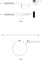
- Each of two ends of a magnesium alloy stent (the mass m of which was 57.26 mg) with a length of 68 mm was cut to form a developing hole with a cross sectional area of 0.5 mm 2 .
- the developing holes were filled with a nickel material with good magnetic conductivity (as shown in FIG. 2 ).
- the clamp used had a length of 30 mm, and the length h of a clamping-free section of the stent was 38 mm.
- a magnet having a maximum magnetic induction intensity B max of 300 mT was used as a magnetic source to apply a magnetic traction force to the stent. When the magnet was arranged at a position that was 3 mm away from the developing holes, the stent might be flat and straight.
- the stent in the above state was placed under an ultrasonic atomization nozzle for spraying.
- a sensofar-non-contact 3D optical profilometer was used to measure coating thicknesses of the sprayed stent, and the difference between the maximum coating thickness and the minimum coating thickness was 0.5 ⁇ m.
- One end of an iron-based absorbable drug elution peripheral stent with a length of 38 mm was fixed by a magnet through magnetic suction (the processing outer diameter of the stent was 1.58 mm; the surface coverage of the stent was 30%; the wall thickness of the stent was 70 ⁇ m; the coverage of supporting rods on a circumferential cross section of the stent was 5%; and the mass m of the stent was 36.24 mg).
- the length h of the clamp without a clamping section was 38mm.
- a magnet having a maximum magnetic induction intensity B max of 400 mT was used as a magnetic source to apply a magnetic traction force to the stent.
- the stent in the above state was placed under an ultrasonic atomization nozzle for spraying.
- a sensofar-non-contact 3D optical profilometer was used to measure coating thicknesses of the sprayed stent, and the difference between the maximum coating thickness and the minimum coating thickness was 0.5 ⁇ m.
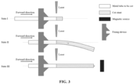
- a metal iron tube to be cut having an outer diameter of 1.6 mm and a length of 200 mm was clamped on a fixing device.
- a material was rotatably fed into a left side at a constant speed of 6 mm/s, and a right side was cut by laser into a specific patterned stent.
- the stent was kept at certain flatness, which would not affect the energy of the laser reaching a surface of the material.
- the cutting length of the stent reached a certain value.
- the stent at the suspended end will tilt due to the force of gravity.
- the inclination angle ⁇ increases as the length of the stent that has been subjected to pattern cutting increases.
- the distance from a part to be cut on a surface of the stent to the laser source was different from the distance originally set for laser cutting. If the difference was larger, the laser energy reaching the surface of the material was lower. Therefore, it is possible that the stent might not be thoroughly cut or a pattern size of the stent after cutting has a relatively large deviation.
- a variable electromagnetic source that could have a maximum magnetic induction intensity of 1000 mT was added at the suspended end of the stent, so that the magnitude of the magnetic induction intensity might be adjusted through the magnetic source; and/or, the magnitude of the magnetic induction intensity on the suspended end of the metal tube might be adjusted by adjusting the distance between the magnetic source and the metal tube.
- the magnetic source was arranged at a position that is 5 mm away from a tail end of the stent. As the metal tube moved towards the magnetic source, on the one hand, the hollow stent was gradually lengthened; and on the other hand, because the distance between the stent and the magnetic source was shortened, there is no need to adjust the magnetic source.
- the length of the suspended end increased, and the magnetic field might adjust the intensity of the magnetic field according to the distance/angle of deviation of the stent relative to the original center position to ensure that the angle of deviation of the stent relative to the center axis was always kept within 5°.
- One end of an iron-based absorbable drug elution peripheral stent with a length of 118 mm was fixed by a clamp with a length of 59 mm (the processing outer diameter of the stent was 1.58 mm; the surface coverage of the stent was 30%; the wall thickness of the stent was 70 ⁇ m; the coverage of supporting rods on a circumferential cross section of the stent was 5%; and the mass m of the stent was 112.53 mg).
Landscapes
- Health & Medical Sciences (AREA)
- Engineering & Computer Science (AREA)
- Biomedical Technology (AREA)
- Life Sciences & Earth Sciences (AREA)
- Animal Behavior & Ethology (AREA)
- Heart & Thoracic Surgery (AREA)
- General Health & Medical Sciences (AREA)
- Public Health (AREA)
- Veterinary Medicine (AREA)
- Transplantation (AREA)
- Vascular Medicine (AREA)
- Oral & Maxillofacial Surgery (AREA)
- Cardiology (AREA)
- Optics & Photonics (AREA)
- Mechanical Engineering (AREA)
- Physics & Mathematics (AREA)
- Plasma & Fusion (AREA)
- Gastroenterology & Hepatology (AREA)
- Pulmonology (AREA)
- Surgery (AREA)
- Molecular Biology (AREA)
- Nuclear Medicine, Radiotherapy & Molecular Imaging (AREA)
- Robotics (AREA)
- Medical Informatics (AREA)
- Orthopedic Medicine & Surgery (AREA)
- Rehabilitation Therapy (AREA)
- Rheumatology (AREA)
- Prostheses (AREA)
- Media Introduction/Drainage Providing Device (AREA)
Applications Claiming Priority (2)
| Application Number | Priority Date | Filing Date | Title |
|---|---|---|---|
| CN202111682990.8A CN116407368A (zh) | 2021-12-31 | 2021-12-31 | 一种保持长管状的植入式医疗器械平直的方法 |
| PCT/CN2022/141879 WO2023125398A1 (zh) | 2021-12-31 | 2022-12-26 | 一种保持长管状的植入式医疗器械平直的方法 |
Publications (2)
| Publication Number | Publication Date |
|---|---|
| EP4458322A1 true EP4458322A1 (de) | 2024-11-06 |
| EP4458322A4 EP4458322A4 (de) | 2026-01-14 |
Family
ID=86997903
Family Applications (1)
| Application Number | Title | Priority Date | Filing Date |
|---|---|---|---|
| EP22914652.7A Pending EP4458322A4 (de) | 2021-12-31 | 2022-12-26 | Verfahren zum halten einer langen röhrenförmigen implantierbaren medizinischen vorrichtung |
Country Status (6)
| Country | Link |
|---|---|
| US (1) | US20250064608A1 (de) |
| EP (1) | EP4458322A4 (de) |
| JP (1) | JP7742941B2 (de) |
| KR (1) | KR20240125617A (de) |
| CN (2) | CN116407368A (de) |
| WO (1) | WO2023125398A1 (de) |
Families Citing this family (1)
| Publication number | Priority date | Publication date | Assignee | Title |
|---|---|---|---|---|
| CN119326559B (zh) * | 2024-12-24 | 2025-03-25 | 吉林大学 | 一种加载双膦酸盐的钽金属多孔锥桩及其制备方法 |
Family Cites Families (10)
| Publication number | Priority date | Publication date | Assignee | Title |
|---|---|---|---|---|
| DE10135876C2 (de) * | 2001-07-24 | 2003-11-13 | Bueltmann Gmbh | Verfahren und Vorrichtung zum Aufbringen von Druck- und/oder Zugkräften auf im wesentlichen stabförmige Werkstücke aus elektrisch leitfähigem und/oder magnetisierbarem Material |
| JP2005198853A (ja) | 2004-01-16 | 2005-07-28 | Asukuremedeiku:Kk | ステントの製造方法 |
| US8069814B2 (en) * | 2006-05-04 | 2011-12-06 | Advanced Cardiovascular Systems, Inc. | Stent support devices |
| EP2559995B1 (de) * | 2011-08-19 | 2013-07-31 | Abbott Laboratories Vascular Enterprises Limited | System und Verfahren zum Erkennen von Strukturdefekten in einem Stent |
| AT519095B1 (de) * | 2016-10-20 | 2018-04-15 | Trumpf Maschinen Austria Gmbh & Co Kg | Beschickungsverfahren für eine Werkzeugmaschine |
| CN109773820B (zh) * | 2017-11-14 | 2022-09-20 | 元心科技(深圳)有限公司 | 一种夹具 |
| CN110756353A (zh) * | 2018-07-27 | 2020-02-07 | 先健科技(深圳)有限公司 | 用于支撑管腔医疗器械的支撑装置及喷涂系统 |
| CN111037344A (zh) * | 2019-12-31 | 2020-04-21 | 华中科技大学 | 一种磁场辅助的超精密加工装置和方法 |
| CN212384723U (zh) * | 2020-05-08 | 2021-01-22 | 济南鼎点数控设备有限公司 | 一种管材加工防甩管设备 |
| CN218190413U (zh) * | 2020-12-31 | 2023-01-03 | 元心科技(深圳)有限公司 | 调整设备 |
-
2021
- 2021-12-31 CN CN202111682990.8A patent/CN116407368A/zh active Pending
-
2022
- 2022-12-26 WO PCT/CN2022/141879 patent/WO2023125398A1/zh not_active Ceased
- 2022-12-26 US US18/724,107 patent/US20250064608A1/en active Pending
- 2022-12-26 CN CN202280086831.8A patent/CN118660679A/zh active Pending
- 2022-12-26 KR KR1020247023881A patent/KR20240125617A/ko active Pending
- 2022-12-26 JP JP2024537889A patent/JP7742941B2/ja active Active
- 2022-12-26 EP EP22914652.7A patent/EP4458322A4/de active Pending
Also Published As
| Publication number | Publication date |
|---|---|
| CN116407368A (zh) | 2023-07-11 |
| US20250064608A1 (en) | 2025-02-27 |
| CN118660679A (zh) | 2024-09-17 |
| WO2023125398A1 (zh) | 2023-07-06 |
| JP7742941B2 (ja) | 2025-09-22 |
| JP2024545309A (ja) | 2024-12-05 |
| KR20240125617A (ko) | 2024-08-19 |
| EP4458322A4 (de) | 2026-01-14 |
Similar Documents
| Publication | Publication Date | Title |
|---|---|---|
| US8591568B2 (en) | Medical devices including metallic films and methods for making same | |
| EP4458322A1 (de) | Verfahren zum halten einer langen röhrenförmigen implantierbaren medizinischen vorrichtung | |
| US8689728B2 (en) | Apparatus for holding a medical device during coating | |
| US20090093870A1 (en) | Method for Holding a Medical Device During Coating | |
| CA2558131C (en) | Medical devices including metallic films and methods for making same | |
| US8124166B2 (en) | Method for loading nanoporous layers with therapeutic agent | |
| JP2007526099A5 (de) | ||
| CA2577197A1 (en) | Medical devices having nanoporous layers and methods for making the same | |
| BRPI0717442B1 (pt) | Método para produção de um stent para redução da taxa de ocorrência e/ou extensão de restenose ou trombose e stent expandível | |
| BRPI0717438B1 (pt) | Método para produzir um stent endovascular radialmente expansível e stent endovascular radialmente expandível | |
| JP2011528939A (ja) | 無機バリアコーティングを有する医療用デバイス | |
| EP2967938A1 (de) | Verfahren zur herstellung eines stents und dadurch hergestellter stent | |
| AU2013301795B2 (en) | Coated stent | |
| US20060171982A1 (en) | Deforming surface of drug eluting coating to alter drug release profile of a medical device | |
| CN113634435B (zh) | 一种植入性生物传感器生产用涂膜结构 | |
| CN209770599U (zh) | 设有斜口标记物的支架及支架系统 | |
| EP2967823A1 (de) | Topografische funktionen und muster auf der oberfläche einer medizinischen vorrichtung und herstellungsverfahren dafür | |
| EP1049419B1 (de) | Verfahren zur herstellung eines aus bandförmigen material, ausdehnbaren stents | |
| EP2197595A2 (de) | System und verfahren zur fixierung einer medizinischen vorrichtung während des beschichtungsvorgangs | |
| Chassagne et al. | Appendix D: Practical Examples |
Legal Events
| Date | Code | Title | Description |
|---|---|---|---|
| STAA | Information on the status of an ep patent application or granted ep patent |
Free format text: STATUS: THE INTERNATIONAL PUBLICATION HAS BEEN MADE |
|
| PUAI | Public reference made under article 153(3) epc to a published international application that has entered the european phase |
Free format text: ORIGINAL CODE: 0009012 |
|
| STAA | Information on the status of an ep patent application or granted ep patent |
Free format text: STATUS: REQUEST FOR EXAMINATION WAS MADE |
|
| 17P | Request for examination filed |
Effective date: 20240723 |
|
| AK | Designated contracting states |
Kind code of ref document: A1 Designated state(s): AL AT BE BG CH CY CZ DE DK EE ES FI FR GB GR HR HU IE IS IT LI LT LU LV MC ME MK MT NL NO PL PT RO RS SE SI SK SM TR |
|
| DAV | Request for validation of the european patent (deleted) | ||
| DAX | Request for extension of the european patent (deleted) | ||
| A4 | Supplementary search report drawn up and despatched |
Effective date: 20251212 |
|
| RIC1 | Information provided on ipc code assigned before grant |
Ipc: A61F 2/08 20060101AFI20251208BHEP Ipc: A61F 2/82 20130101ALI20251208BHEP |