EP4458243A1 - Selbstreinigende staubsammelbasis und staubsammelsystem - Google Patents
Selbstreinigende staubsammelbasis und staubsammelsystem Download PDFInfo
- Publication number
- EP4458243A1 EP4458243A1 EP22913372.3A EP22913372A EP4458243A1 EP 4458243 A1 EP4458243 A1 EP 4458243A1 EP 22913372 A EP22913372 A EP 22913372A EP 4458243 A1 EP4458243 A1 EP 4458243A1
- Authority
- EP
- European Patent Office
- Prior art keywords
- dust collection
- dust
- self
- dust bag
- cleaning
- Prior art date
- Legal status (The legal status is an assumption and is not a legal conclusion. Google has not performed a legal analysis and makes no representation as to the accuracy of the status listed.)
- Pending
Links
Images






Classifications
-
- A—HUMAN NECESSITIES
- A47—FURNITURE; DOMESTIC ARTICLES OR APPLIANCES; COFFEE MILLS; SPICE MILLS; SUCTION CLEANERS IN GENERAL
- A47L—DOMESTIC WASHING OR CLEANING; SUCTION CLEANERS IN GENERAL
- A47L11/00—Machines for cleaning floors, carpets, furniture, walls, or wall coverings
- A47L11/40—Parts or details of machines not provided for in groups A47L11/02 - A47L11/38, or not restricted to one of these groups, e.g. handles, arrangements of switches, skirts, buffers, levers
-
- A—HUMAN NECESSITIES
- A47—FURNITURE; DOMESTIC ARTICLES OR APPLIANCES; COFFEE MILLS; SPICE MILLS; SUCTION CLEANERS IN GENERAL
- A47L—DOMESTIC WASHING OR CLEANING; SUCTION CLEANERS IN GENERAL
- A47L11/00—Machines for cleaning floors, carpets, furniture, walls, or wall coverings
- A47L11/40—Parts or details of machines not provided for in groups A47L11/02 - A47L11/38, or not restricted to one of these groups, e.g. handles, arrangements of switches, skirts, buffers, levers
- A47L11/4013—Contaminants collecting devices, i.e. hoppers, tanks or the like
- A47L11/4025—Means for emptying
-
- A—HUMAN NECESSITIES
- A47—FURNITURE; DOMESTIC ARTICLES OR APPLIANCES; COFFEE MILLS; SPICE MILLS; SUCTION CLEANERS IN GENERAL
- A47L—DOMESTIC WASHING OR CLEANING; SUCTION CLEANERS IN GENERAL
- A47L11/00—Machines for cleaning floors, carpets, furniture, walls, or wall coverings
- A47L11/40—Parts or details of machines not provided for in groups A47L11/02 - A47L11/38, or not restricted to one of these groups, e.g. handles, arrangements of switches, skirts, buffers, levers
- A47L11/4013—Contaminants collecting devices, i.e. hoppers, tanks or the like
-
- A—HUMAN NECESSITIES
- A47—FURNITURE; DOMESTIC ARTICLES OR APPLIANCES; COFFEE MILLS; SPICE MILLS; SUCTION CLEANERS IN GENERAL
- A47L—DOMESTIC WASHING OR CLEANING; SUCTION CLEANERS IN GENERAL
- A47L11/00—Machines for cleaning floors, carpets, furniture, walls, or wall coverings
- A47L11/40—Parts or details of machines not provided for in groups A47L11/02 - A47L11/38, or not restricted to one of these groups, e.g. handles, arrangements of switches, skirts, buffers, levers
- A47L11/4013—Contaminants collecting devices, i.e. hoppers, tanks or the like
- A47L11/4016—Contaminants collecting devices, i.e. hoppers, tanks or the like specially adapted for collecting fluids
-
- A—HUMAN NECESSITIES
- A47—FURNITURE; DOMESTIC ARTICLES OR APPLIANCES; COFFEE MILLS; SPICE MILLS; SUCTION CLEANERS IN GENERAL
- A47L—DOMESTIC WASHING OR CLEANING; SUCTION CLEANERS IN GENERAL
- A47L11/00—Machines for cleaning floors, carpets, furniture, walls, or wall coverings
- A47L11/40—Parts or details of machines not provided for in groups A47L11/02 - A47L11/38, or not restricted to one of these groups, e.g. handles, arrangements of switches, skirts, buffers, levers
- A47L11/4091—Storing or parking devices, arrangements therefor; Means allowing transport of the machine when it is not being used
-
- A—HUMAN NECESSITIES
- A47—FURNITURE; DOMESTIC ARTICLES OR APPLIANCES; COFFEE MILLS; SPICE MILLS; SUCTION CLEANERS IN GENERAL
- A47L—DOMESTIC WASHING OR CLEANING; SUCTION CLEANERS IN GENERAL
- A47L9/00—Details or accessories of suction cleaners, e.g. mechanical means for controlling the suction or for effecting pulsating action; Storing devices specially adapted to suction cleaners or parts thereof; Carrying-vehicles specially adapted for suction cleaners
- A47L9/10—Filters; Dust separators; Dust removal; Automatic exchange of filters
- A47L9/14—Bags or the like; Rigid filtering receptacles; Attachment of, or closures for, bags or receptacles
- A47L9/1427—Means for mounting or attaching bags or filtering receptacles in suction cleaners; Adapters
-
- A—HUMAN NECESSITIES
- A47—FURNITURE; DOMESTIC ARTICLES OR APPLIANCES; COFFEE MILLS; SPICE MILLS; SUCTION CLEANERS IN GENERAL
- A47L—DOMESTIC WASHING OR CLEANING; SUCTION CLEANERS IN GENERAL
- A47L9/00—Details or accessories of suction cleaners, e.g. mechanical means for controlling the suction or for effecting pulsating action; Storing devices specially adapted to suction cleaners or parts thereof; Carrying-vehicles specially adapted for suction cleaners
- A47L9/10—Filters; Dust separators; Dust removal; Automatic exchange of filters
- A47L9/14—Bags or the like; Rigid filtering receptacles; Attachment of, or closures for, bags or receptacles
- A47L9/1427—Means for mounting or attaching bags or filtering receptacles in suction cleaners; Adapters
- A47L9/1436—Connecting plates, e.g. collars, end closures
- A47L9/1445—Connecting plates, e.g. collars, end closures with closure means
-
- A—HUMAN NECESSITIES
- A47—FURNITURE; DOMESTIC ARTICLES OR APPLIANCES; COFFEE MILLS; SPICE MILLS; SUCTION CLEANERS IN GENERAL
- A47L—DOMESTIC WASHING OR CLEANING; SUCTION CLEANERS IN GENERAL
- A47L9/00—Details or accessories of suction cleaners, e.g. mechanical means for controlling the suction or for effecting pulsating action; Storing devices specially adapted to suction cleaners or parts thereof; Carrying-vehicles specially adapted for suction cleaners
- A47L9/10—Filters; Dust separators; Dust removal; Automatic exchange of filters
- A47L9/14—Bags or the like; Rigid filtering receptacles; Attachment of, or closures for, bags or receptacles
- A47L9/149—Emptying means; Reusable bags
-
- A—HUMAN NECESSITIES
- A47—FURNITURE; DOMESTIC ARTICLES OR APPLIANCES; COFFEE MILLS; SPICE MILLS; SUCTION CLEANERS IN GENERAL
- A47L—DOMESTIC WASHING OR CLEANING; SUCTION CLEANERS IN GENERAL
- A47L2201/00—Robotic cleaning machines, i.e. with automatic control of the travelling movement or the cleaning operation
- A47L2201/02—Docking stations; Docking operations
- A47L2201/024—Emptying dust or waste liquid containers
Definitions
- the present disclosure relates to the field of cleaning robot technologies, and in particular to a self-cleaning dust collection base and a dust collection system.
- An embodiment of the present disclosure provides a self-cleaning dust collection base, including a self-cleaning dust collection base body.
- the self-cleaning dust collection base body includes:
- a dust collection system including an automatic cleaning device and the self-cleaning dust collection base described above.
- first, second, third, etc. may be used for description of the embodiments of the present disclosure, the present disclosure is not limited to these terms. These terms are only intended for a distinguishing purpose. For example, without departing from the scope of the embodiments of the present disclosure, “first” may also be referred to as “second”, and similarly, “second” may also be referred to as “first”.
- an embodiment of the present disclosure provides a self-cleaning dust collection base, which collects garbage in the dust box of an automatic cleaning device into a dust collection bin of the self-cleaning dust collection base in a centralized manner by means of a dust collection system, thereby reducing the frequency of garbage disposal by a user and improving the user experience.
- FIG. 1 schematically shows a schematic diagram of an overall structure of the self-cleaning dust collection base
- FIG. 2 schematically shows a schematic structural diagram of a self-cleaning dust collection base body from which a sewage tank, a clean water tank and a dust collection hood are removed in the present disclosure.
- the self-cleaning dust collection base may be defined by the following three axes as defined, which are perpendicular to each other: a transverse axis Y, a front-rear axis X and a central vertical axis Z.
- a direction opposite to an arrow along the front-rear axis X, i.e., a direction in which the automatic cleaning device enters the self-cleaning dust collection base is marked as a "rearward direction”
- a direction of an arrow along the front-rear axis X i.e., a direction in which the automatic cleaning device leaves the self-cleaning dust collection base is marked as a "forward direction”.
- the transverse axis Y is substantially in a width direction of the self-cleaning dust collection base body.
- the vertical axis Z is a direction along upward extension from a bottom surface of the self-cleaning dust collection base.
- a direction in which a self-cleaning dust collection base bottom plate 1000 protrudes from a self-cleaning dust collection base body 2000 is a forward direction
- a direction of a rear wall of the self-cleaning dust collection base body 2000 is a rearward direction.
- a dust collection bin 3000 is located on a left side of the self-cleaning dust collection base
- a clean water tank 4000 is located on a right side of the dust collection bin 3000
- a sewage tank 5000 is located on a right side of the clean water tank 4000.
- the self-cleaning dust collection base includes the self-cleaning dust collection base bottom plate 1000 and the self-cleaning dust collection base body 2000.
- the self-cleaning dust collection base bottom plate 1000 and the self-cleaning dust collection base body 2000 are detachably connected.
- the self-cleaning dust collection base bottom plate 1000 is detachably connected to a body base 6000 at a lower portion of the self-cleaning dust collection base body 2000.
- the detachable connection can facilitate transportation and maintenance.
- the self-cleaning dust collection base body 2000 is configured to collect garbage in a dust box of an automatic cleaning device.
- components such as the dust collection bin 3000, the clean water tank 4000 and the sewage tank 5000 may also be arranged side by side on the self-cleaning dust collection base body 2000.
- the self-cleaning dust collection base body 2000 includes a water storage chamber 2700 and a dust collection chamber 2100.
- the water storage chamber 2700 with an opening facing upward and forward, is arranged at a top of the self-cleaning dust collection base body 2000, and the water storage chamber may further include a clean water bin for accommodating the clean water tank 4000 and a sewage bin for accommodating the sewage tank 5000.
- the dust collection chamber 2100 (with an opening facing upward and forward) and the water storage chamber 2700 are arranged at the top end of the self-cleaning dust collection base body 2000 side by side.
- a dust collection hood 2800 that matches the opening of the dust collection chamber 2100 is arranged on the dust collection chamber 2100, and the dust collection hood 2800 is detachably placed on the dust collection chamber 2100.
- the dust collection chamber 2100 and the dust collection hood 2800 jointly form the dust collection bin 3000 for accommodating a garbage receiving device.
- At least a part of an outer surface of the dust collection hood 2800 serves as a part of an exterior surface of the self-cleaning dust collection base.
- the body base 6000 is arranged at a lower portion of the self-cleaning dust collection base body 2000.
- the body base 6000 is integrally arranged at the lower portion of the self-cleaning dust collection base body 2000.
- the body base 6000 also abuts against the self-cleaning dust collection base bottom plate 1000.
- the self-cleaning dust collection base bottom plate 1000 and the body base 6000 are arranged in sequence in a second direction, where the second direction is a direction opposite to an arrow of the front-rear axis X.
- a dust collection port 6100 is formed in the body base 6000 and substantially located at an edge of the body base 6000 connected to the self-cleaning dust collection base bottom plate 1000.
- the dust collection port 6100 is configured to interface with a dust outlet of the automatic cleaning device, and the garbage in the dust box 300 of the automatic cleaning device enters the dust collection chamber 2100 of the self-cleaning dust collection base body 2000 through the dust collection port 6100.
- a sealing gasket is also arranged around the dust collection port 6100 and configured to seal the dust collection port 6100 and the dust outlet of the automatic cleaning device after they interface with each other so as to avoid leakage of the garbage.
- the body base 6000 further includes a cleaning tank 6200.
- the cleaning tank 6200 is configured to clean cleaning components on the automatic cleaning device, for example, to replenish a wet cleaning module of the automatic cleaning device with a cleaning fluid, and/or to accommodate sundries removed from the wet cleaning module, and/or to collect sewage generated in the process of cleaning the wet cleaning module, so as to facilitate subsequent treatment of the sundries and sewage.
- the cleaning tank 6200 is arranged behind the dust collection port 6100.
- the self-cleaning dust collection base further includes an air duct, one end of the air duct is communicated with the dust collection port 6100 of the body base 6000, and the other end of the air duct is communicated with the dust collection chamber 2100.
- the self-cleaning dust collection base When the self-cleaning dust collection base is in a state of dust collection, sufficient negative pressure is formed in the dust collection bin 3000 to suck the garbage from the dust box 300 to the dust bag in the dust collection chamber 2100 through the dust collection port 6100 and the air duct.
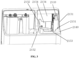
- the dust collection chamber 2100 includes a dust collection chamber rear wall 2134 and a pair of opposite dust collection chamber side walls.
- the dust collection chamber side walls further include a first dust collection chamber side wall 2131 and a second dust collection chamber side wall 2132, the first dust collection chamber side wall is close to an outer wall of the self-cleaning dust collection base body 2000, and the first dust collection chamber side wall 2131 and the second dust collection chamber side wall 2132 are arranged opposite to each other and both adjoin the dust collection chamber rear wall 2134.
- an end face of each dust collection chamber side wall may be of an arc structure, and the height of the dust collection chamber side wall may have a trend of decreasing gradually in a direction of the arrow of the front-rear axis X.
- the height of the dust collection chamber side wall is equal to that of the dust collection chamber rear wall 2134 at a point where the dust collection chamber side wall adjoins the dust collection chamber rear wall 2134.
- the dust collection chamber side wall is of the arc structure that is low in the front and high at the back, which can facilitate placement and removal of the dust collection hood 2800 and improve the aesthetic degree to a certain extent.
- the first dust collection chamber side wall 2131, the second dust collection chamber side wall 2132, and the dust collection chamber rear wall 2134 are of an integrated structural with the self-cleaning dust collection base body 2000, so that the stability of the dust collection chamber 2100 can be improved and the dust collection chamber 2100 can be prevented from shaking relative to the self-cleaning dust collection base body 2000.
- the dust collection chamber 2100 further includes a circumferential inner wall 2150, and the circumferential inner wall 2150 extends from a bottom wall of the dust collection chamber 2100 in a direction away from the self-cleaning dust collection base body 2000.
- the dust collection chamber rear wall 2134 and the dust collection chamber side walls are arranged around the circumferential inner wall 2150 and spaced apart from the circumferential inner wall 2150.
- the circumferential inner wall 2150 may be of different heights at different positions. In some embodiments, the height of the circumferential inner wall 2150 has a trend of decreasing gradually in the direction of the arrow of the front-rear axis X.
- the structural design of the circumferential inner wall 2150 which is low in the front and high at the back, can facilitate placement and removal of the dust collection hood 2800.
- the circumferential inner wall 2150 may be of a closed-loop structure, and further includes a front inner wall 2153, a first side inner wall 2151, a rear inner wall 2154 and a second side inner wall 2152 connected end to end in sequence.
- the front inner wall 2153 is opposite to the rear inner wall 2154
- the first side inner wall 2151 is opposite to the second side inner wall 2152.
- all the inner walls of the circumferential inner wall 2150 may also be in correspondence with the dust collection chamber rear wall 2134 and the dust collection chamber side walls.
- first side inner wall 2151 and the first dust collection chamber side wall 2131 are located on the same side and spaced apart from each other
- the rear inner wall 2154 and the dust collection chamber rear wall 2134 are located on the same side and spaced apart from each other
- second side inner wall 2152 and the second dust collection chamber side wall 2132 are located on the same side and spaced apart from each other.
- the circumferential inner wall 2150 and a bottom wall of the dust collection chamber 2100 are of an integrated structure, so that the stability of the circumferential inner wall 2150 can be improved.
- the dust collection chamber 2100 further includes a sealing gasket 2140, the sealing gasket 2140 is arranged around the circumferential inner wall 2150, and the dust collection chamber rear wall 2134 and the dust collection chamber side walls are arranged around the sealing gasket 2140.
- the sealing gasket 2140 is of a closed-loop structure, and a width at each part of the sealing gasket 2140 is equal to or slightly larger than an interval between the circumferential inner wall 2150 and the dust collection chamber rear wall 2134, and an interval between the circumferential inner wall 2150 and the dust collection chamber side walls, so that the sealing gasket 2140 may be in close contact with the circumferential inner wall 2150, the dust collection chamber rear wall 2134 and the dust collection chamber side walls.
- the sealing gasket 2140 may be made from various natural or synthetic rubbers.
- a dust bag support 2110 is also arranged in the dust collection chamber 2100, and the dust bag support 2110 is configured to install a dust bag.
- the dust bag support 2110 is arranged inside the dust collection chamber 2100, and extends from a bottom of the dust collection chamber in a direction away from the self-cleaning dust collection base body 2000.
- the dust bag support 2110 may be arranged on the circumferential inner wall 2150 of the dust collection chamber 2100 by means of a fixing component, for example, a screw, or fixed to the bottom wall of the dust collection chamber through a bottom of the dust bag support 2110.
- the dust bag support 2110 is arranged at the first side inner wall 2151, and a side wall of the dust bag support 2110 away from the dust collection chamber 2100 may be integrally formed with the first side inner wall 2151, so that the stability of the dust bag support 2110 can be improved.
- the dust bag support 2110 has a hollow cavity inside, and the hollow cavity serves as a part of the air duct of the self-cleaning dust collection base, for example, as a tail end of the air duct.
- the dust bag support 2110 includes a support side wall facing the inside of the dust collection bin 3000, the support side wall is provided with a dust outlet port, the dust outlet port is communicated with the dust collection port 6100 through the air duct, and the air duct is configured to guide the garbage into the dust collection bin 3000, for example, into the dust bag in the dust collection bin 3000.
- the dust outlet port is configured to be communicated with an inlet of the dust bag, for collecting the garbage into the dust bag.
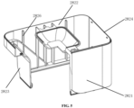
- the dust collection hood 2800 includes a dust collection hood cover body 2810 and a dust collection hood wall 2820.
- the dust collection hood cover body 2810 is located above the dust collection hood wall 2820, and the dust collection hood wall 2820 extends from the dust collection hood cover body 2810 in a direction away from the dust collection hood cover body 2810.
- the dust collection hood cover body 2810 and the dust collection hood wall 2820 jointly define an accommodating space.
- the circumferential inner wall 2150 is accommodated in the accommodating space, and a free end of the dust collection hood wall 2820 away from the dust collection hood cover body 2810 is attached to the sealing gasket 2140 to form the closed dust collection bin 3000.
- the dust collection hood wall 2820 further includes a front wall 2823 of the dust collection hood, a first side wall 2821 of the dust collection hood, a rear wall 2824 of the dust collection hood and a second side wall 2822 of the dust collection hood, which are connected end to end in sequence.
- the front wall 2823 of the dust collection hood and the rear wall 2824 of the dust collection hood are arranged opposite to each other, and the first side wall 2821 of the dust collection hood and the second side wall 2822 of the dust collection hood are arranged opposite to each other.
- the dust collection hood 2800 In response to the dust collection hood 2800 being placed on the dust collection chamber 2100, at least a part of the first side wall 2821 of the dust collection hood is sandwiched between the first dust collection chamber side wall 2131 and the first side inner wall 2151, at least a part of the second side wall 2822 of the dust collection hood is sandwiched between the second dust collection chamber side wall 2132 and the second side inner wall 2152, and the rear wall 2824 of the dust collection hood is sandwiched between the dust collection chamber rear wall 2134 and the rear inner wall 2154.
- the dust collection hood 2800 further includes a pull handle portion 2811, and the pull handle portion 2811 is arranged at a side of the dust collection hood cover body 2810 away from the dust collection hood wall 2820.
- the pull handle portion 2811 may be a pull ring, a pull rod, a handle or other structures arranged on the dust collection hood cover body 2810.
- the dust collection hood 2800 further includes a stopper 2825.
- the stopper 2825 is arranged on the dust collection hood wall 2820, and the stopper 2825 may cooperate with a limiting portion arranged in the dust collection chamber 2100, such that the dust collection hood 2800 is firmly placed on the dust collection chamber 2100 without shaking.
- the limiting portion may be arranged on at least one of the dust collection chamber rear wall 2134 and the dust collection chamber side walls.
- the stopper 2825 and the limiting portion are arranged in pairs and match each other. In the embodiment shown in FIG.
- the stopper 2825 is arranged on the second side wall 2822 of the dust collection hood, and the limiting portion corresponding to the stopper 2825 is arranged on the second dust collection chamber side wall 2132.
- the stopper 2825 abuts against the limiting portion in response to the dust collection hood 2800 being placed on the dust collection chamber 2100.
- At least one of the dust collection chamber bottom wall, the circumferential inner wall 2150 and the dust collection hood wall 2820 is provided with a supporting rib 2826.
- the supporting rib 2826 may be of a strip-shaped structure which protrudes outward relative to a surface.
- the supporting rib 2826 is at least arranged on an inner surface of the second side wall 2822 of the dust collection hood, and a plurality of supporting ribs 2826 are arranged on the inner surface of the second side wall 2822 of the dust collection hood.
- the dust bag in the dust collection bin 3000 may not be attached to the dust collection chamber bottom wall, the circumferential inner wall 2150 and/or the dust collection hood wall 2820, such that an airflow can flow out of the dust bag without being affected by the attachment.
- the present disclosure further provides a dust collection system, including an automatic cleaning device and the self-cleaning dust collection base described in the foregoing embodiments.
- the dust collection hood and the dust collection chamber are combined more closely under the action of a fan, which further improves the dust collection efficiency.
- the exposed design of the dust collection hood makes it convenient for a user to visualize the situation inside the dust collection hood and deal with the dust collection chamber in a more timely manner, e.g., to replace the dust bag.
- an embodiment of the present disclosure provides a self-cleaning dust collection base.
- the garbage in the dust box of the automatic cleaning device is collected into the dust collection bin of the self-cleaning dust collection base by means of a dust collection system.
- the dust bag support and the dust bag in the dust collection bin the garbage in the dust box is basically transferred to the dust bag located in the dust collection bin without leakage, thus reducing the frequency of garbage disposal by the user and improving the user experience.
- the dust bag adopts a design that a fastening plate corporates with a sliding plate. When the dust bag is removed from the dust bag support, the sliding plate is in a closed position, preventing the garbage in the dust bag from being scattered in the dust collection bin.
- FIG. 1 is a schematic diagram of an overall structure of the self-cleaning dust collection base
- FIG. 2 is a schematic structural diagram of a self-cleaning dust collection base body from which a sewage tank, a clean water tank and a dust collection hood are removed.
- a direction in which a self-cleaning dust collection base bottom plate 1000 protrudes from a self-cleaning dust collection base body 2000 is a forward direction
- a direction of a rear wall of the self-cleaning dust collection base body 2000 is a rearward direction.
- a dust collection bin 3000 is located on a left side of the self-cleaning dust collection base
- a clean water tank 4000 is located on a right side of the dust collection bin 3000
- a sewage tank 5000 is located on a right side of the clean water tank 4000.
- the self-cleaning dust collection base body 2000 is configured to collect garbage in the dust bag of the automatic cleaning device.
- components such as the dust collection bin 3000, the clean water tank 4000, and the sewage tank 5000 may also be arranged side by side on the self-cleaning dust collection base body 2000.
- the self-cleaning dust collection base body 2000 includes a water storage chamber 2700 and a dust collection chamber 2100.
- the water storage chamber 2700 with an opening facing upward and forward, is arranged at a top of the self-cleaning dust collection base body 2000.
- the water storage chamber may further include a clean water bin for accommodating the clean water tank 4000 and a sewage bin for accommodating the sewage tank 5000.
- the dust collection chamber 2100 and the water storage chamber 2700 are arranged at the top end of the self-cleaning dust collection base body 2000 side by side.
- a dust collection hood 2800 that matches the opening of the dust collection chamber 2100 is arranged on the dust collection chamber 2100, and the dust collection hood 2800 is detachably placed on the dust collection chamber 2100.
- the dust collection chamber 2100 and the dust collection chamber 2800 jointly form the dust collection bin 3000.
- the upward and forward designs of the water storage chamber 2700 and the dust collection chamber 2100 facilitate installment and removal of the sewage tank 5000, the clean water tank 4000 and the dust collection hood 2800.
- a body base 6000 is arranged at a lower portion of the self-cleaning dust collection base body 2000.
- the body base 6000 is integrally arranged at the lower portion of the self-cleaning dust collection base body 2000.
- the body base 6000 also abuts against the self-cleaning dust collection base bottom plate 1000.
- the self-cleaning dust collection base bottom plate 1000 and the body base 6000 are arranged in sequence in a second direction, and the second direction is a direction opposite to the arrow of the front-rear axis X.
- a dust collection port 6100 is formed in the body base 6000 and substantially located at an edge of the body base 6000 connected to the self-cleaning dust collection base bottom plate 1000.
- the dust collection port 6100 is configured to interface with a dust outlet of the automatic cleaning device, and the garbage in the dust box 300 of the automatic cleaning device enters the dust collection chamber 2100 of the self-cleaning dust collection base body 2000 through the dust collection port 6100.
- a sealing rubber gasket is also arranged around the dust collection port 6100 and configured to seal the dust collection port 6100 and the dust outlet of the automatic cleaning device after the dust collection port 6100 interfaces with the dust outlet of the automatic cleaning device so as to avoid leakage of the garbage.
- the body base 6000 further includes a cleaning tank 6200.
- the cleaning tank 6200 is configured to clean cleaning component(s) on the automatic cleaning device, for example, to replenish a wet cleaning module of the automatic cleaning device with a cleaning fluid, and/or to accommodate sundries removed from the wet cleaning module, and/or to collect sewage generated in the process of cleaning the wet cleaning module, so as to facilitate subsequent treatment of the sundries and sewage.
- the cleaning tank 6200 is arranged behind the dust collection port 6100.
- the self-cleaning dust collection base further includes an air duct, one end of the air duct is communicated with the dust collection port 6100 of the body base 6000, and the other end of the air duct is communicated with the dust collection chamber 2100.
- the self-cleaning dust collection base When the self-cleaning dust collection base is in a state of dust collection, sufficient negative pressure is formed in the dust collection bin 3000 to suck the garbage in the dust box 300 into the dust bag in the dust collection chamber 2100 through the dust collection port 6100 and the air duct.
- FIG. 6 is a schematic structural diagram of a dust bag support according to some embodiments of the present disclosure, in which a sliding baffle is in a first position; and FIG. 7 is another schematic structural diagram of the dust bag support according to some embodiments of the present disclosure, in which the sliding baffle is in a second position.
- the self-cleaning dust collection base further includes a dust bag support 2110, and the dust bag support 2110 is configured to install the dust bag.
- the dust bag support 2110 is arranged in the dust collection bin 3000, for example, arranged on an inner side wall of the dust collection bin 3000 by means of a fixing component, for example, a screw, or fixed to a bottom surface of the dust collection bin 3000 by the bottom of the dust bag support 2110.
- the dust bag support 2110 is internally provided with a hollow cavity, and the hollow cavity is used as a part of the air duct of the self-cleaning dust collection base, for example, as a tail end of the air duct.
- the dust bag support 2110 includes a support side wall 2111 facing the inside of the dust collection bin 3000, and the support side wall 2111 is provided with a dust outlet port 2112.
- the dust outlet port 2112 is communicated with the dust collection port 6100 by means of the air duct, and the air duct is configured to guide the garbage into the dust collection bin 3000, for example, into the dust bag in the dust collection bin 3000.
- the dust outlet port 2112 is configured to be communicated with an inlet of the dust bag, for collecting the garbage into the dust bag.
- the dust bag support 2110 further includes a sliding baffle 2113 capable of sliding on the support side wall 2111.
- the sliding baffle 2113 is configured to be switchable between a first position and a second position.
- the sliding baffle 2113 shields the dust outlet port 2112 in response to the sliding baffle 2113 being in the first position, and the sliding baffle 2113 exposes the dust outlet port 2112 in response to the sliding baffle 2113 being in the second position.
- the dust bag is a consumable item detachably installed in the dust bag support 2110.
- the sliding baffle 2113 may shield the dust outlet port 2112, and isolate the dust collection bin 3000 from the air duct, so that a suction force generated by the fan cannot enter the air duct from the dust collection bin, which prevents the garbage from entering the dust collection bin 3000 where the dust bag is not installed.
- FIG. 8 is a schematic structural diagram of a dust bag according to some embodiments of the present disclosure, in which a sliding plate is in a closed position.
- FIG. 9 is another schematic structural diagram of the dust bag according to some embodiments of the present disclosure, in which the sliding plate is in an open position.
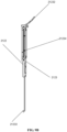
- FIG. 9A is a schematic diagram of a partial structure of the dust bag according to some embodiments of the present disclosure.
- FIG. 9B is a schematic structural diagram of a cross-section in FIG. 9A.
- FIG. 9A shows a cross-section of the dust bag, while the dust bag is not shown in FIG. 9 or FIG. 9B .
- the present disclosure further provides a dust bag 2120.
- the dust bag 2120 is configured to be detachably installed on the dust bag support 2110 for collecting the garbage.
- the dust bag 2120 includes a dust bag body 2121, a fastening plate 2122 and a sliding plate 2123.
- the dust bag body 2121 is made of, for example, a material that is breathable but can filter fine particles, such as a non-woven fabric or a paper material, and the dust bag body 2121 is configured to accommodate the garbage.
- the fastening plate 2122 is fixedly connected to the dust bag body 2121.
- the fastening plate 2122 is provided with a fastening plate opening 21221, and the fastening plate opening 21221 serves as an inlet of the dust bag body 2121.
- the sliding plate 2123 is slidably connected to the fastening plate 2122 and configured to be switched between the closed position and the open position.
- the sliding plate 2123 shields the fastening plate opening 21221 in response to the sliding plate 2123 being in the closed position, and the sliding plate 2123 exposes the fastening plate opening 21221 in response to the sliding plate 2123 being in the open position.
- the sliding plate 2123 is provided with a sliding plate opening 21231.
- an orthographic projection of the sliding plate opening 21231 on the fastening plate 2122 does not overlap with the fastening plate opening 2821, and the sliding plate 2123 shields the fastening plate opening 22121, as shown in FIG. 8 .
- an orthographic projection of the sliding plate opening 21231 on the fastening plate 2122 at least partially overlaps with the fastening plate opening 21221, and the sliding plate 2123 exposes at least a part of the fastening plate opening 21221 through the sliding plate opening 21231, as shown in FIG. 9 .
- a size of the sliding plate opening 21231 is, for example, larger than that of the fastening plate opening 21221, and the orthographic projection of the sliding plate opening 21231 on the fastening plate 2122 covers the fastening plate opening 21221 in response to the sliding plate 2123 being in the closed position.
- the size of the sliding plate opening 21231 is, for example, smaller than that of the fastening plate opening 21221, and the orthographic projection of the sliding plate opening 21231 on the fastening plate 2122 falls within the fastening plate opening 21221 in response to the sliding plate 2123 being in the closed position.
- the size of the sliding plate opening 21231 is, for example, equal to that of the fastening plate opening 21221, and the orthogonal projection of the sliding plate opening 21231 on the fastening plate 2122 substantially coincides with the fastening plate opening 21221 in response to the sliding plate 2123 being in the closed position.
- the sliding fit between the sliding plate 2123 and the fastening plate 2122 allows the inlet of the dust bag to be closed to prevent the garbage in the dust bag from leakage.
- an edge of the fastening plate opening 21221 is provided with a flexible rubber ring 21224 that protrudes toward the sliding plate 2123.
- the flexible rubber ring 21224 passes through the sliding plate opening 21231 and protrudes in a direction away from the sliding plate 2123, so that when the sliding plate opening 21231 interfaces with the fastening plate opening 21221, a slit at the position where the two openings of the sliding plate 2123 and the fastening plate 2122 interface with each other is blocked to make the sliding plate opening 21231 and the fastening plate opening 21221 interface with each other in a sealing manner.
- At least a part of the flexible rubber ring 21224 may be squeezed between the sliding plate 2123 and the fastening plate 2122 to increase the friction therebetween, so that the sliding plate 2123 and the fastening plate 2122 can only slide relative to each other under the action of a certain external force, and the sliding plate 2123 can be stably kept in the closed position to prevent the garbage in the dust bag from being scattered.
- the sliding plate 2123 may slide relative to the fastening plate 2122 in a first direction M.
- the sliding plate 2123 includes a limiting bump 21243 arranged on at least one side of the sliding plate 2123, for example, on two sides of the sliding plate 2123.
- the number of the limiting bumps 21243 is, for example two, and the limiting bumps 21243 protrude from the sliding plate 2123 in a second direction perpendicular to the first direction M.
- the fastening plate 2122 includes limiting components 21223 arranged at two ends of the fastening plate 2122 in the first direction and configured to block the limiting bumps 21233 in the first direction M so as to prevent the sliding plate 2123 from disengaging from the fastening plate 2122.
- the number of the limiting components 21223 is, for example four, and the limiting components 21223 are symmetrically distributed on two sides of the fastening plate 2122.
- the limiting bumps 21233 may only move between the corresponding limiting components 21223 located at two ends of the fastening plate 2122 in the first direction.
- the sliding plate 2123 further includes a handle portion 21232 disposed at an end of the sliding plate in the first direction M and configured to be conveniently held by an operator to move the sliding plate 2123.
- the dust bag 2120 is configured to be detachably installed on the dust bag support 2110.
- the sliding baffle 2123 is in the second position to expose the dust outlet port
- the sliding plate is in the open position
- the fastening plate opening 21221 interfaces with the dust outlet port 2112.
- the sliding baffle 2113 is in the first position
- the dust outlet port 2112 is shielded, and a suction force generated by the fan cannot enter the air duct from the dust collection bin, thus preventing the garbage from entering the dust collection bin 3000 where the dust bag 2120 is not installed.
- the sliding plate 2123 When the dust bag 2120 is removed from the dust bag support 2110, the sliding plate 2123 is in the closed position to prevent the garbage in the dust bag from being scattered in the dust collection bin. Moreover, the sealed dust bag also prevents the garbage in the dust bag from being scattered to an external environment.
- the sliding plate 2123 shields the fastening plate opening 21221 of the fastening plate 2122, so that when the dust bag is installed in the dust bag support 2110, the sliding baffle 2113 may be pushed from the first position to the second position and fixed in the second position under the cooperation of the sliding plate 2123 and the fastening plate 2122.
- the sliding plate 2123 shields the fastening plate opening 21221 to avoid leakage of the garbage.
- the fastening plate opening 21221 i.e., the inlet of the dust bag
- the garbage in the dust box of the automatic cleaning device may be collected into the dust bag body 2121 through the dust collection port 6100 on the body base 6000, the air duct in the self-cleaning dust collection base, the dust outlet port 2112 on the dust bag support 2110 and the fastening plate opening 21221 on the dust bag 2120 in sequence.
- FIG. 10 is a schematic diagram of a pre-assembled structure of the dust bag support and the dust bag according to some embodiments of the present disclosure
- FIG. 11 is a schematic diagram of an assembled structure of the dust bag support and the dust bag according to some embodiments of the present disclosure.
- the dust bag support 2110 includes a socket 2114, and at least a part of the sliding baffle 2113 is located in the socket 2114, so that the sliding baffle 2113 may slide in an extension direction X' of the socket 2114, and thus be switched between the first position and the second position.
- the number of the sockets 2114 is, for example, one or more.
- the number of the sockets 2114 is, for example, two, and the sockets 2114 are respectively arranged at two opposite ends of the support side wall 2111 of the dust bag support 2110.
- the two sockets 2114 respectively accommodate the two opposite ends of the sliding baffle 2113, so that the sliding baffle 2113 may slide in the extension direction X' of the socket 2114.
- the fastening plate 2122 and the sliding plate 2123 of the dust bag 2120 are configured to be insertable into the socket 2114 to slide along the socket 2114 in the extension direction X', and the sliding baffle 2113 is pushed to slide in the extension direction X' of the socket such that the dust bag 2120 is installed in the dust bag support 2110.
- two ends of the fastening plate 2122 and the sliding plate 2123 of the dust bag 2120 may be respectively inserted into the two sockets 2114 described above.
- the sliding plate 2123 In response to the dust bag 2120 being installed on the dust bag support 2110, the sliding plate 2123 is in the open position to expose the fastening plate opening 21221, and the sliding baffle 2113 is in the second position to expose the dust outlet port 2112, so that the fastening plate opening 21221 interfaces with the dust outlet port 2112.
- the dust bag 2120 moves relative to the dust bag support 2110 in the extension direction X' of the socket 2114.
- the fastening plate 2122 and the sliding plate 2123 of the dust bag 2120 face the support side wall 2111 of the dust bag support 2110.
- the sliding baffle 2113 may be pushed to move from the first position to the second position.
- a sliding baffle protrusion 21131 is arranged at a lower end of the sliding baffle 2113, and the sliding baffle protrusion 21131 is a strip-shaped protrusion along a lower edge of the sliding baffle 2113 toward the dust collection bin 3000.
- the lower end of the sliding plate 2123 may abut against the sliding baffle protrusion 21131 after the sliding plate 2123 is inserted into the socket 2114. Since the lower end of the sliding plate 2123 abuts against the sliding baffle protrusion 21131, the sliding baffle 2113 may also be pushed to slide in the extension direction X' of the socket when the sliding plate 2123 slides downward in the extension direction X' of the socket 2114.
- a sliding plate protrusion 21233 is also arranged at the lower end of the sliding plate 2123, and the sliding plate protrusion 21233 may be a strip-shaped protrusion along the lower edge of the sliding plate 2123 toward the dust collection bin 3000.
- the sliding plate protrusion 21233 may exactly abut against the upper side of the sliding baffle protrusion 21131 after the sliding plate 2123 is inserted into the socket 2114. Since the sliding plate protrusion 21233 abuts against the sliding baffle protrusion 21131, the sliding baffle 2113 may also be pushed to slide in the extension direction X' of the socket when the sliding plate 2123 slides downward in the extension direction X' of the socket 2114.
- FIG. 11 is a sectional view of an assembled structure of the dust bag support and the dust bag according to some embodiments of the present disclosure
- FIG. 12 is a schematic diagram of an assembled structure of the dust bag support and the dust bag according to some embodiments of the present disclosure.
- the socket 2114 is internally provided with a fastening portion 21141, for example, an elastic snap joint, which can move in an approximate arc line as shown by an arrow in FIG. 12 .
- the fastening plate 2122 is provided with a fastening plate slot 21222 that matches the fastening portion 21141, and the fastening portion 21141 is snapped in the fastening plate slot 21222 in response to the dust bag 2120 being installed on the dust bag support 2110.
- the fastening plate 2122 slides to a snap-in position in the extension direction X' of the socket 2114, the fastening plate opening 21221 interfaces with the dust outlet port 2112, and the fastening portion 21141 is cooperatively snapped with the fastening plate slot 21222, so that the dust bag 2120 is fixed to the dust bag support 2110.
- a limiting bump 212234 on the sliding plate 2123 also serves as an unlocking bump 21234 (also referred to as the unlocking bump 21234), and is configured to squeeze, during withdrawal of the sliding plate 2123 from the socket 2114, the fastening portion 21141 to cause the fastening portion 21141 to disengage from the fastening plate slot 21222, so as to release the fastening plate 2122 from the fastening portion 21141 and make the dust bag 2120 successfully disengage from the dust bag support 2110.
- the unlocking bump 21234 also has a limiting function and cooperates with the limiting component 21223 on the fastening plate 2122 to prevent the sliding plate 2123 from disengaging from the fastening plate 2122.
- the dust bag support 2110 is provided with an elastic component 2115, for example, a spring.
- the elastic component 2115 is connected to the sliding baffle 2113, and is configured to make the sliding baffle 2113 to have a trend to be in the first position.
- the sliding baffle 2113 is in the first position under the action of the elastic component 2115 when the sliding baffle 2113 is not subjected to an external force, so that the sliding baffle 2113 shields the dust outlet port 2112.
- the elastic component 2115 is located inside the dust bag support 2110, and an extension direction of the elastic component 2115 is basically the same as that of the socket 2114.
- the elastic component 2115 has one end fixed to an upper portion of the dust bag support 2110, and the other end connected to the sliding baffle 2113.
- the number of the elastic components 2115 may be one or more. When the number of the elastic components 2115 is two, for example, the two elastic components may be respectively arranged at two opposite ends of the dust bag support 2110.
- the sliding baffle 2113 on the dust bag support 2110 is in the first position, the dust outlet port 2112 is shielded, the sliding plate 2123 on the dust bag 2120 is in the closed position, and the fastening plate opening 2122 is shielded, just as shown in FIG. 8 .
- the fastening plate 2122 and the sliding plate 2123 are inserted into the socket 2114 in the extension direction X' of the socket 2114, and the sliding plate 2123 gradually moves from the closed position to the open position relative to the fastening plate 2122 when a user holds the handle portion 21232 of the sliding plate 2123 to push the dust bag 2120 into the socket 2114, such that the sliding plate opening 21231 on the sliding plate 2123 is aligned with the fastening plate opening 21221 on the fastening plate 2122.
- the fastening plate 2122 and the sliding plate 2123 push the sliding baffle 2113 to move from the first position to the second position, so that the sliding baffle 2113 exposes the dust outlet port 2112.
- the fastening plate 2122 slides to a snap-in position in the extension direction X' of the socket 2114, the fastening plate opening 21221 interfaces with the dust outlet port 2112, and the fastening portion 21141 is cooperatively snapped with the fastening plate slot 21222, so that the dust bag 2120 is fixed to the dust bag support 2110.
- the flexible rubber ring 21224 on the dust bag passes through the sliding plate opening 21231 and abuts against an edge of the dust outlet port 2112, so that the fastening plate opening 21221 of the dust bag interfaces with the dust outlet port 2112 of the dust bag support in a sealing manner, so as to avoid leakage of the garbage during dust collection.
- the operator holds the handle portion 21232 of the sliding plate 2123 to gradually withdraw the sliding plate 2123 from the socket 2114 of the dust bag support 2110.
- the sliding plate 2123 gradually moves from the open position to the closed position relative to the fastening plate 2122, so that the sliding plate 2123 shields the fastening plate opening 21221.
- the unlocking bump 21234 on the sliding plate 2123 squeezes the fastening portion 21141, so that the fastening portion 21141 disengages from the fastening plate slot 21222.
- the handle portion 21232 of the sliding plate 2123 can be continuously pulled to withdraw the sliding plate 2123 and the fastening plate 2122 from the socket 2114 of the dust bag support 2110.
- the dust bag 2120 disengages from the dust bag support 2110, and the sliding baffle 2113 returns to the first position under the action of the elastic component, so that the sliding baffle 2113 shields the dust outlet port 2112.
- the support side wall of the dust bag support facing the inside of the dust collection bin is provided with the dust outlet port configured to interface with the inlet of the dust bag.
- the dust bag support further includes the sliding baffle capable of sliding on the support side wall.
- the sliding baffle is configured to be switched between a first position and a second position. The sliding baffle shields the dust outlet port in response to the sliding baffle being in the first position, and the sliding baffle exposes the dust outlet port in response to the sliding baffle being in the second position.
- the self-cleaning dust collection base further includes a dust bag detachably installed on the dust bag support.
- the dust bag includes:
- the sliding baffle is in the first position to shield the dust outlet port in response to the dust bag not being installed on the dust bag support, and the sliding baffle is in the second position to expose the dust outlet port in response to the dust bag being installed on the dust bag support, so that the fastening plate opening interfaces with the dust outlet port.
- the dust bag further includes a sliding plate connected to the fastening plate in a slidable manner and configured to be switched between a third position and a fourth position, the sliding plate shields the fastening plate opening in response to the sliding plate being in the third position, and the sliding plate exposes the fastening plate opening in response to the sliding plate being in the fourth position.
- the sliding plate is provided with a sliding plate opening; in response to the sliding plate being in the third position, the sliding plate opening does not overlap with the fastening plate opening such that the sliding plate shields the fastening plate opening; and in response to the sliding plate being in the fourth position, the sliding plate opening substantially overlaps with the fastening plate opening such that the sliding plate exposes the fastening plate opening.
- the dust bag support includes a socket, and at least a part of the sliding baffle is located in the socket, so that the sliding baffle slides in an extension direction of the socket.
- the fastening plate and the sliding plate are configured to be insertable into the socket to slide in the extension direction of the socket; the sliding baffle is pushed to slide in the extension direction of the socket such that the dust bag is installed on the dust bag support; and in response to the dust bag being installed on the dust bag support, the sliding plate is in the fourth position to expose the fastening plate opening, and the sliding baffle is in the second position to expose the dust outlet port, so that the fastening plate opening interfaces with the dust outlet port.
- the dust bag support is provided with an elastic component, and the elastic component is connected to the sliding baffle and is configured to make the sliding baffle have a trend to be in the first position.
- the fastening plate is provided with a fastening plate slot
- the socket is internally provided with a fastening portion
- the fastening portion is snapped in the fastening plate slot in response to the dust bag being installed on the dust bag support.
- the fastening plate is also provided with an unlocking bump, and the unlocking bump is configured to make the fastening portion disengage from the fastening plate slot during detachment of the dust bag from the dust bag support.
- the present disclosure further provides a dust collection system, including an automatic cleaning device and the self-cleaning dust collection base described in the foregoing embodiments.
- the garbage in the dust box of the automatic cleaning device is collected into the dust collection bin of the self-cleaning dust collection base by means of the dust collection system; and by providing the dust bag support and the dust bag in the dust collection bin, the garbage in the dust box is basically transferred into the dust bag located in the dust collection bin without leakage, thus reducing the frequency of garbage disposal by the user and improving the user experience.
Landscapes
- Engineering & Computer Science (AREA)
- Mechanical Engineering (AREA)
- Filtering Of Dispersed Particles In Gases (AREA)
- Cleaning Implements For Floors, Carpets, Furniture, Walls, And The Like (AREA)
- Filters For Electric Vacuum Cleaners (AREA)
- Electric Vacuum Cleaner (AREA)
Applications Claiming Priority (2)
| Application Number | Priority Date | Filing Date | Title |
|---|---|---|---|
| CN202111675497.3A CN114587213A (zh) | 2021-12-31 | 2021-12-31 | 自清洁集尘座及集尘系统 |
| PCT/CN2022/109801 WO2023124086A1 (zh) | 2021-12-31 | 2022-08-02 | 自清洁集尘座及集尘系统 |
Publications (2)
| Publication Number | Publication Date |
|---|---|
| EP4458243A1 true EP4458243A1 (de) | 2024-11-06 |
| EP4458243A4 EP4458243A4 (de) | 2025-12-31 |
Family
ID=81803807
Family Applications (1)
| Application Number | Title | Priority Date | Filing Date |
|---|---|---|---|
| EP22913372.3A Pending EP4458243A4 (de) | 2021-12-31 | 2022-08-02 | Selbstreinigende staubsammelbasis und staubsammelsystem |
Country Status (6)
| Country | Link |
|---|---|
| US (1) | US20250057381A1 (de) |
| EP (1) | EP4458243A4 (de) |
| JP (1) | JP7818706B2 (de) |
| CN (1) | CN114587213A (de) |
| AU (1) | AU2022428552B2 (de) |
| WO (1) | WO2023124086A1 (de) |
Families Citing this family (2)
| Publication number | Priority date | Publication date | Assignee | Title |
|---|---|---|---|---|
| CN114587213A (zh) * | 2021-12-31 | 2022-06-07 | 北京石头世纪科技股份有限公司 | 自清洁集尘座及集尘系统 |
| CN114587214A (zh) * | 2021-12-31 | 2022-06-07 | 北京石头世纪科技股份有限公司 | 自清洁集尘座及集尘系统 |
Family Cites Families (20)
| Publication number | Priority date | Publication date | Assignee | Title |
|---|---|---|---|---|
| JP2770738B2 (ja) * | 1993-08-12 | 1998-07-02 | 松下電器産業株式会社 | 電気掃除機の集塵袋 |
| CN102028435A (zh) * | 2009-09-29 | 2011-04-27 | 乐金电子(天津)电器有限公司 | 吸尘器集尘袋支架组件 |
| DE102014119191A1 (de) * | 2014-12-19 | 2016-06-23 | Vorwerk & Co. Interholding Gmbh | Basisstation für einen Staubsauger |
| US9462920B1 (en) * | 2015-06-25 | 2016-10-11 | Irobot Corporation | Evacuation station |
| EP4331455A3 (de) * | 2016-05-09 | 2024-05-29 | Aktiebolaget Electrolux | Staubbehälter für einen staubsauger |
| CN109068912B (zh) * | 2016-05-09 | 2022-03-18 | 伊莱克斯公司 | 用于生产灰尘容器的方法及灰尘容器的连接板 |
| CN109008798B (zh) * | 2017-06-09 | 2024-08-09 | 天佑电器(苏州)有限公司 | 集尘袋固定防尘结构 |
| US10842334B2 (en) * | 2018-05-04 | 2020-11-24 | Irobot Corporation | Filtering devices for evacuation stations |
| DE102018211712A1 (de) * | 2018-07-13 | 2020-01-16 | Festool Gmbh | Verschlusseinrichtung, System, Partikelauffanganordnung und Saugvorrichtung |
| KR102793630B1 (ko) * | 2019-07-02 | 2025-04-11 | 삼성전자주식회사 | 로봇청소기 스테이션 |
| KR102761429B1 (ko) * | 2019-08-05 | 2025-02-05 | 삼성전자주식회사 | 로봇 청소기의 스테이션 |
| CN212186371U (zh) * | 2019-12-31 | 2020-12-22 | 佛山市云米电器科技有限公司 | 维护站和扫地机器人 |
| CN212281203U (zh) * | 2020-03-16 | 2021-01-05 | 尚科宁家(中国)科技有限公司 | 集尘袋及集尘设备 |
| CN111436869B (zh) * | 2020-05-19 | 2025-03-07 | 苏州科沃斯软件科技有限公司 | 一种集尘装置以及机器人清洁基站 |
| CN113827135A (zh) * | 2020-06-08 | 2021-12-24 | 美智纵横科技有限责任公司 | 吸尘设备 |
| CN112515547B (zh) * | 2020-09-11 | 2025-08-12 | 深圳银星智能集团股份有限公司 | 一种垃圾回收基站以及清洁系统 |
| CN212307728U (zh) * | 2020-09-11 | 2021-01-08 | 深圳市银星智能科技股份有限公司 | 一种垃圾回收基站以及清洁系统 |
| CN112890678B (zh) * | 2021-03-30 | 2025-05-13 | 深圳银星智能集团股份有限公司 | 集尘装置及清洁机器人系统 |
| CN113679315B (zh) * | 2021-09-30 | 2025-01-17 | 深圳银星智能集团股份有限公司 | 集尘装置及清洁机器人系统 |
| CN114587213A (zh) * | 2021-12-31 | 2022-06-07 | 北京石头世纪科技股份有限公司 | 自清洁集尘座及集尘系统 |
-
2021
- 2021-12-31 CN CN202111675497.3A patent/CN114587213A/zh active Pending
-
2022
- 2022-08-02 AU AU2022428552A patent/AU2022428552B2/en active Active
- 2022-08-02 US US18/725,349 patent/US20250057381A1/en active Pending
- 2022-08-02 EP EP22913372.3A patent/EP4458243A4/de active Pending
- 2022-08-02 JP JP2024539407A patent/JP7818706B2/ja active Active
- 2022-08-02 WO PCT/CN2022/109801 patent/WO2023124086A1/zh not_active Ceased
Also Published As
| Publication number | Publication date |
|---|---|
| JP2025501208A (ja) | 2025-01-17 |
| EP4458243A4 (de) | 2025-12-31 |
| WO2023124086A1 (zh) | 2023-07-06 |
| JP7818706B2 (ja) | 2026-02-20 |
| AU2022428552B2 (en) | 2025-12-04 |
| US20250057381A1 (en) | 2025-02-20 |
| CN114587213A (zh) | 2022-06-07 |
| AU2022428552A1 (en) | 2024-08-08 |
Similar Documents
| Publication | Publication Date | Title |
|---|---|---|
| EP4458238A1 (de) | Staubbeutel, selbstreinigender staubauffangsitz und staubsammelsystem | |
| EP4458243A1 (de) | Selbstreinigende staubsammelbasis und staubsammelsystem | |
| EP2201875B1 (de) | Staubsauger und Zyklonabscheidermodul dafür | |
| KR101119615B1 (ko) | 진공청소기 | |
| CN113616120B (zh) | 一种集尘回收站 | |
| US3675399A (en) | Vacuum cleaner | |
| EP4458240A1 (de) | Selbstreinigende staubsammelbasis und staubsammelsystem | |
| CN212281203U (zh) | 集尘袋及集尘设备 | |
| EP4449964A1 (de) | Staubsammelpfahl und automatisches reinigungssystem | |
| CN215687487U (zh) | 一种集尘回收站 | |
| CN216854604U (zh) | 尘袋、自清洁集尘座及集尘系统 | |
| CN216495158U (zh) | 自清洁集尘座及集尘系统 | |
| CN216495159U (zh) | 自清洁集尘座及集尘系统 | |
| JP2015093021A (ja) | 電気掃除機 | |
| CN105072963B (zh) | 集尘装置 | |
| CN215738716U (zh) | 一种旋风分离器及集尘回收站 | |
| CN216854575U (zh) | 集尘桩及自动清洁系统 | |
| KR100996561B1 (ko) | 진공청소기 | |
| CN216293918U (zh) | 一种扫地机器人 | |
| CN119385458A (zh) | 一种自动集尘的吸尘装置 | |
| KR20060116995A (ko) | 진공청소기의 집진유니트 |
Legal Events
| Date | Code | Title | Description |
|---|---|---|---|
| STAA | Information on the status of an ep patent application or granted ep patent |
Free format text: STATUS: THE INTERNATIONAL PUBLICATION HAS BEEN MADE |
|
| PUAI | Public reference made under article 153(3) epc to a published international application that has entered the european phase |
Free format text: ORIGINAL CODE: 0009012 |
|
| STAA | Information on the status of an ep patent application or granted ep patent |
Free format text: STATUS: REQUEST FOR EXAMINATION WAS MADE |
|
| 17P | Request for examination filed |
Effective date: 20240722 |
|
| AK | Designated contracting states |
Kind code of ref document: A1 Designated state(s): AL AT BE BG CH CY CZ DE DK EE ES FI FR GB GR HR HU IE IS IT LI LT LU LV MC MK MT NL NO PL PT RO RS SE SI SK SM TR |
|
| DAV | Request for validation of the european patent (deleted) | ||
| DAX | Request for extension of the european patent (deleted) | ||
| A4 | Supplementary search report drawn up and despatched |
Effective date: 20251202 |
|
| RIC1 | Information provided on ipc code assigned before grant |
Ipc: A47L 11/40 20060101AFI20251126BHEP Ipc: A47L 9/28 20060101ALI20251126BHEP Ipc: A47L 9/14 20060101ALI20251126BHEP |