EP4456560A1 - Akustisches wiedergabesystem mit verbesserter unterdrückungskompensation - Google Patents
Akustisches wiedergabesystem mit verbesserter unterdrückungskompensation Download PDFInfo
- Publication number
- EP4456560A1 EP4456560A1 EP23204816.5A EP23204816A EP4456560A1 EP 4456560 A1 EP4456560 A1 EP 4456560A1 EP 23204816 A EP23204816 A EP 23204816A EP 4456560 A1 EP4456560 A1 EP 4456560A1
- Authority
- EP
- European Patent Office
- Prior art keywords
- driver
- playback system
- audio
- acoustic playback
- primary
- Prior art date
- Legal status (The legal status is an assumption and is not a legal conclusion. Google has not performed a legal analysis and makes no representation as to the accuracy of the status listed.)
- Withdrawn
Links
Images



Classifications
-
- H—ELECTRICITY
- H04—ELECTRIC COMMUNICATION TECHNIQUE
- H04R—LOUDSPEAKERS, MICROPHONES, GRAMOPHONE PICK-UPS OR LIKE ACOUSTIC ELECTROMECHANICAL TRANSDUCERS; ELECTRIC HEARING AIDS; PUBLIC ADDRESS SYSTEMS
- H04R1/00—Details of transducers, loudspeakers or microphones
- H04R1/20—Arrangements for obtaining desired frequency or directional characteristics
- H04R1/22—Arrangements for obtaining desired frequency or directional characteristics for obtaining desired frequency characteristic only
- H04R1/227—Arrangements for obtaining desired frequency or directional characteristics for obtaining desired frequency characteristic only using transducers reproducing the same frequency band
-
- H—ELECTRICITY
- H04—ELECTRIC COMMUNICATION TECHNIQUE
- H04R—LOUDSPEAKERS, MICROPHONES, GRAMOPHONE PICK-UPS OR LIKE ACOUSTIC ELECTROMECHANICAL TRANSDUCERS; ELECTRIC HEARING AIDS; PUBLIC ADDRESS SYSTEMS
- H04R1/00—Details of transducers, loudspeakers or microphones
- H04R1/20—Arrangements for obtaining desired frequency or directional characteristics
- H04R1/22—Arrangements for obtaining desired frequency or directional characteristics for obtaining desired frequency characteristic only
- H04R1/26—Spatial arrangements of separate transducers responsive to two or more frequency ranges
-
- H—ELECTRICITY
- H04—ELECTRIC COMMUNICATION TECHNIQUE
- H04R—LOUDSPEAKERS, MICROPHONES, GRAMOPHONE PICK-UPS OR LIKE ACOUSTIC ELECTROMECHANICAL TRANSDUCERS; ELECTRIC HEARING AIDS; PUBLIC ADDRESS SYSTEMS
- H04R29/00—Monitoring arrangements; Testing arrangements
- H04R29/001—Monitoring arrangements; Testing arrangements for loudspeakers
-
- H—ELECTRICITY
- H04—ELECTRIC COMMUNICATION TECHNIQUE
- H04R—LOUDSPEAKERS, MICROPHONES, GRAMOPHONE PICK-UPS OR LIKE ACOUSTIC ELECTROMECHANICAL TRANSDUCERS; ELECTRIC HEARING AIDS; PUBLIC ADDRESS SYSTEMS
- H04R3/00—Circuits for transducers
- H04R3/12—Circuits for transducers for distributing signals to two or more loudspeakers
-
- H—ELECTRICITY
- H04—ELECTRIC COMMUNICATION TECHNIQUE
- H04R—LOUDSPEAKERS, MICROPHONES, GRAMOPHONE PICK-UPS OR LIKE ACOUSTIC ELECTROMECHANICAL TRANSDUCERS; ELECTRIC HEARING AIDS; PUBLIC ADDRESS SYSTEMS
- H04R2201/00—Details of transducers, loudspeakers or microphones covered by H04R1/00 but not provided for in any of its subgroups
- H04R2201/02—Details casings, cabinets or mounting therein for transducers covered by H04R1/02 but not provided for in any of its subgroups
- H04R2201/021—Transducers or their casings adapted for mounting in or to a wall or ceiling
-
- H—ELECTRICITY
- H04—ELECTRIC COMMUNICATION TECHNIQUE
- H04S—STEREOPHONIC SYSTEMS
- H04S7/00—Indicating arrangements; Control arrangements, e.g. balance control
- H04S7/30—Control circuits for electronic adaptation of the sound field
- H04S7/302—Electronic adaptation of stereophonic sound system to listener position or orientation
-
- H—ELECTRICITY
- H04—ELECTRIC COMMUNICATION TECHNIQUE
- H04S—STEREOPHONIC SYSTEMS
- H04S7/00—Indicating arrangements; Control arrangements, e.g. balance control
- H04S7/30—Control circuits for electronic adaptation of the sound field
- H04S7/305—Electronic adaptation of stereophonic audio signals to reverberation of the listening space
Definitions
- the present application relates to the field of acoustic playback systems.
- the present application relates to the compensation of cancellation effects that occur in an acoustic playback system.
- an acoustic playback system in an aspect of the present application, includes a housing.
- the housing has a first side.
- the housing has a second side opposite the first side.
- the housing has a plurality of walls connecting the first side with the second side.
- the acoustic playback system includes at least one amplifier.
- the at least one amplifier is configured to receive an electrical signal representative of an audio and output an amplified audio signal.
- the acoustic playback system includes a primary driver.
- the primary driver is configured to receive the amplified audio signal.
- the primary driver is configured to output a primary audio, based on the amplified audio signal, from the first side.
- the acoustic playback system includes a filler driver.
- the filler driver is configured to receive the amplified audio signal.
- the filler driver is configured to output a secondary audio, based on the amplified audio signal from the second side.
- the acoustic playback system includes a filter.
- the filter can be in communication with the filler driver.
- the filter is configured to apply a filter to the electrical signal and/or the amplified audio signal.
- the primary driver output is spaced away from the filler driver output.
- embodiments of the disclosed acoustic playback system can avoid and/or reduce the cancellation effect normally experienced by an acoustic playback system located near a wall, or other acoustically reflecting surface.
- the reflections by the wall lead to destructive interference, thereby creating dead zones of acoustic cancellation (e.g., dips), where the acoustic output of the acoustic playback system will not be heard.
- a secondary driver e.g., a filler driver
- the disclosed acoustic playback system can reduce or eliminate such a dead zone thereby providing an improved hearing experience to a user.
- the filler driver can contribute to overall sound pressure.
- an acoustic playback system e.g., acoustic playback device, acoustical playback system, audio reproduction system, audio reproduction device.
- the acoustic playback system can be one of a sound bar, a speaker, a video bar, a loudspeaker, and a subwoofer.
- the acoustic playback system can include a communication bar, a satellite speaker, a Bluetooth speaker, a built-in monitor and/or television speaker, and a speaker phone.
- the acoustic playback system can include one or more speakers.
- the acoustic playback system can be configured to be located and/or mounted and/or installed at a location near an acoustically reflective surface, such as a wall.
- the acoustic playback system can include one or more components configured to connect the acoustic playback system to and/or near a wall.
- the acoustic playback system can be configured to be received within a frame or other component for locating the acoustic playback system near a wall.
- a wall can be any surface which is acoustically reflective.
- the acoustic playback system can include a housing.
- the housing can be configured to retain one or more electrical and/or acoustic components of the playback system.
- the housing can have a plurality of different shapes, and the general shape of the housing is not limiting.
- the housing can be one of a rectangular prism, a triangular prism, a cylinder, a cone, etc.
- the housing can be formed from one or more housing components.
- the housing can define an outer surface of the acoustic playback system.
- the housing can include one or more apertures for allowing audio to be expressed from the acoustic playback system.
- the housing can retain one or more of the at least one amplifier, the primary driver, the filler driver, and the filter. Further, the housing can retain at least one processor and at least one microphone. The housing can further retain further components, such as electrical components.
- the housing has a first side.
- the housing has a second side opposite the first side.
- the housing can have a plurality of walls connecting the first side with the second side.
- the housing can have at least one wall connecting the first side with the second side.
- the first side may be generally opposite the second side, such as if the housing is not symmetric.
- the second side may be a continuation of the first side.
- the housing may be spherical.
- the first side, the second side, and the plurality of walls may define the outer surface of the housing.
- the first side may be considered a front side.
- the first side may be configured to be located away from a wall (e.g., a standing wall, a rear wall, a structural wall), such as a wall of a location (e.g., room) that the acoustic playback system is in.
- the first side may be configured to be located towards a user of the acoustic playback system.
- the second side may be considered a back side.
- the second side may be configured to be located towards a wall (e.g., a standing wall, a rear wall, a structural wall), such as a wall of a location (e.g., room) that the acoustic playback system is in.
- the second side may be configured to be located away from a user of the acoustic playback system.
- the acoustic playback system can include at least one amplifier.
- the at least one amplifier is located in the housing.
- the at least one amplifier can be configured to receive an electrical signal representative of an audio (e.g., audio signal, audio stream).
- the at least one amplifier can be configured to output an amplified audio signal.
- the at least one amplifier can be configured to output an amplified audio signal based on the audio.
- the at least one amplifier can be configured to output an amplified audio signal based on the electrical signal.
- the at least one amplifier can apply an amplification to the electrical signal.
- the at least one amplifier can apply gain to the electrical signal.
- the at least one amplifier can be configured to output the amplified audio signal to the primary driver and/or the filler driver.
- the acoustic playback system can include a plurality of amplifiers.
- a first amplifier can provide a first amplified audio signal to the primary driver and a second amplifier can provide a second amplified audio signal to the filler driver.
- the acoustic playback system can include a primary driver.
- a driver can be, for example, a transducer and/or an audio source.
- the primary driver can be a speaker.
- the primary driver can be at least partially located within the housing.
- the primary driver can be configured to receive the amplified audio signal.
- the primary driver can be configured to output a primary audio signal.
- the primary driver can be configured to output a primary audio signal, based on the amplified audio signal from the first side.
- the primary audio signal may be an audio signal configured for listening by a user of the acoustic playback system.
- the primary driver can have its output (e.g., the location where the primary audio is leaving the primary driver) directed towards the first side of the housing.
- the primary driver can output the primary audio from the first side of the housing.
- the primary driver is an omnidirectional audio source.
- the primary driver is an audio source with significant forwards and rearward radiation.
- the primary driver is a directional primary driver.
- the primary driver can have an audio outlet directed towards the first side.
- the acoustic playback system can include a filler driver.
- a driver can be, for example, a transducer and/or an audio source.
- the filler driver can be a speaker.
- the filler driver can be at least partially located within the housing.
- the filler driver can be configured to receive the amplified audio signal.
- the filler driver can be configured to output a secondary audio signal.
- the filler driver can be configured to output a secondary audio signal, based on the amplified audio signal from the second side.
- the acoustic playback system can include at least two drivers (e.g., a plurality of drivers).
- the filler driver can have its output (e.g., the location where the secondary audio is leaving the filler driver) directed towards the second side of the housing.
- the filler driver can output the secondary audio from the second side of the housing.
- the output of the filler driver can be directed generally opposite that of the primary driver.
- the filler driver may have an audio outlet directed towards the second side.
- the filler driver is an omnidirectional filler driver. In one or more example acoustic playback systems, the filler driver is a directional filler driver.
- the acoustic playback system can include a filter (such as a filter bank).
- the filter can be in communication with the filler driver.
- the filter can be in communication with the primary driver.
- the filter can be configured to apply a filter (e.g., attenuate, boost, pass, apply an equalization, configured to filter) to the electrical signal and/or the amplified audio signal.
- the filter can be, for example, a high-pass filter, a low-pass filter, band-pass filter, etc.
- the acoustic playback system can include at least one filter.
- the acoustic playback system can include a plurality of filters.
- the filter can be located in different signal pathways of the acoustic playback system.
- the filter can be located before the at least one amplifier.
- the filter is applied to the electrical signal.
- the filter is located after the at least one amplifier. In such embodiments, the filter is applied to the amplified audio signal.
- the primary driver output is spaced away from the filter driver output.
- an output location of the primary driver is spaced away from an output location of the filter driver.
- the primary audio leaves the primary driver at a location spaced away from where the secondary audio leaves the secondary driver.
- the primary driver and the filler driver are spaced away from one another.
- the filler driver output is spaced away from the first side from the primary driver output.
- the filler driver and the primary driver are not located on the same side of the housing. This can prevent further destructive interference between the primary driver and the filler driver.
- the filler driver and the primary driver are not aligned.
- the filler driver and the primary driver are not aligned in a line between the first side and the second side.
- the filler driver and the primary driver are not aligned in a line between the plurality of walls.
- the filler driver and the primary driver can be facing away from one another.
- the output location of the filler driver and the primary driver can be facing away from one another.
- the primary driver output can be spaced away from the filter driver output between the first side and the second side.
- the primary driver can be located closer to the first side than the filler driver. In one or more examples, the filler driver can be located closer to the second side than the primary driver.
- the filler driver can be configured to add an acoustic signal (e.g., the secondary audio) in the frequency range where the cancellation occurs. To do this the filler driver can be placed in a - in terms of acoustic wavelength - significantly different distance from the wall than the primary driver.
- an acoustic signal e.g., the secondary audio
- the primary audio and the secondary audio are the same audio.
- the primary driver and the filler driver are both outputting the same audio.
- primary audio and the secondary audio are at the same volume and/or the same gain and/or the same frequency.
- the primary driver and the filler driver receive the same amplified audio signal.
- the primary audio and the secondary audio are different audio.
- the filter can modify the electrical signal and/or the amplified audio signal so that the amplified audio signal received by the primary driver and the filler driver are different.
- a low-pass filter can be applied for the primary driver and a high-pass filter can be applied for the filler driver.
- at least one processor can be configured to process the electrical signal and/or the amplified audio signal for modifying between the primary driver and filler driver.
- the secondary audio has a lower gain than the primary audio.
- the primary audio may have a higher gain than the secondary audio.
- the primary audio may be louder than the secondary audio.
- the secondary audio may have a lower volume than the primary audio.
- any audio which enters the cancellation zone of the primary audio can be reduce and/or eliminate any cancellation, the secondary audio may not need to be as loud as the primary audio for its effects to be felt by a user of the acoustic playback system.
- Cancellation zone can include cancellation band and/or cancellation range.
- the cancellation zone can be a band in audio frequency.
- the filler driver is configured to add an acoustic signal for the secondary audio into a frequency range where a cancellation in the primary audio occurs.
- the reflective cancellation may occur with the primary audio at a certain frequency while other frequencies are not cancelled.
- the secondary audio may be output in the frequency that is cancelled.
- the acoustic signal can be within the frequency band of the cancellation.
- the acoustic signal can be identical to the primary signal. However it can have another amplitude or phase as a function of the filters that is applied prior to the amplifier, after the amplifier or the transfer function of the driver itself which may not be identical to the primary driver.
- the signal is no different from the primary signal in terms of linearity except that it in practice might be closer to the noise floor, e.g., the signal information - again in the relevant frequency range - is preserved.
- the acoustic play back system can be configured to be mounted to a wall.
- the acoustic playback system can include a mounting frame.
- the acoustic playback system can include one or more mounting components configured to be affixed to a wall.
- the housing can include one or more mounting components configured to be affixed to a wall.
- the filler driver upon mounting of the acoustical playback system, is configured to face a wall.
- the second side upon mounting, the second side may face the wall.
- the filler driver is configured to reduce a comb-filter effect of the primary driver. In one or more example acoustic playback systems, the filler driver is configured to eliminate a comb-filter effect of the primary driver. The comb-filter effect occurs due to destructive interference of the primary audio of the primary driver caused by reflection of the primary audio. Through the use of the filler driver, by adding the secondary audio, the cancellation of the primary audio may be overcome.
- the filler driver is configured to produce the secondary audio at a same signal as the primary audio in low frequencies and a different signal as the primary audio in high frequencies.
- one method to increase output in a loudspeaker is to use two drivers (e.g., primary driver and filler driver) at low frequencies. This increases their dynamic capabilities. The outputs of the two drivers will sum and, since the frequencies are low, the wavelength is long, and summing will be close to ideal (adding 6dB).
- the at least one amplifier comprises a primary amplifier in communication with the primary driver and a filler amplifier in communication with the filler driver.
- the acoustic playback system can include a plurality of amplifiers.
- the primary amplifier and the filler amplifier receive the same electrical signal.
- the primary amplifier may output a primary amplified audio signal.
- the primary driver can be configured to receive the primary amplified audio signal and output a primary audio, based on the primary amplified audio signal, from the first side.
- the filler amplifier may output a secondary amplified audio signal.
- the filler driver can be configured to receive the secondary amplified audio signal and output a secondary audio, based on the secondary amplified audio signal, from the second side.
- the primary amplifier and the filler amplifier may be the same type of amplifier.
- the primary amplifier and the filler amplifier may be different types of amplifiers.
- the primary amplifier may provide a first amplification to the electric signal.
- the filler amplifier may provide a second amplification to the electric signal.
- the first amplification may be the same as the second amplification.
- the first amplification may be different than the second amplification.
- the first application may be greater than the second amplification.
- the filter can be located (e.g., positioned) between the at least one amplifier and the primary driver and/or the filler driver.
- the filter can be used on the amplified audio signal.
- the filter is a conditioning filter
- the filler amplifier is positioned between the conditioning filter and the filler driver.
- a conditioning filter can be a filter which conditions a signal. As discussed herein, the filter can condition the signal to be as good as possible at adding signal to the cancellation frequency range. In certain examples, the conditioning filter can be any type of filter.
- the conditioning filter is an adaptive conditioning filter.
- An adaptive filter can be a filter that adapts automatically to achieve an optimized state.
- the wall can have different properties (e.g., absorption coefficients) or the acoustic playback system can be placed close to a TV-screen affecting the reflection, or the acoustic playback system is place on some kind of stand away from a wall, and thus adaptiveness can be an advantage.
- the acoustic playback system is configured to determine the state of the location of the acoustic playback system.
- the acoustic playback system can be configured to receive user input indicative of the state of the location.
- the acoustic playback system can include one or more microphones, and the state of the location can be determined by the acoustic feedback playback through feedback received by the one or more microphones.
- the filter is a low-pass filter positioned between the at least one amplifier and the filler driver. In other words, the filter only applies the low-pass filtration to the filler driver.
- a different filler can be in communication with the primary driver. In some instances, no filter is in communication with the primary driver.
- the filter is a high-pass filter positioned between the at least one amplifier and the primary driver. In other words, the filter only applies the high-pass filtration to the filler driver.
- the filter includes a primary filter and a filler filter.
- the primary filter can be a high pass filter in communication with the primary driver.
- the filler filter can be a low pass filter in communication with the filler driver.
- the filler driver has a higher impedance than the primary driver.
- the primary driver may have an impedance between 4-8ohms.
- the filler driver may have an impedance of at least 4-8 times higher than the primary driver in order to not influence the primary audio (e.g., the output) of the primary drier.
- the filler driver can have an impedance of 16-32 ohms.
- the filler driver may have an impedance of 32-64 ohms.
- the filler driver can have an impedance of 16-64 ohms.
- a high pass filter can be applied to the primary audio and a low pass filter can be applied to the secondary audio.
- a high pass filter can be applied to the secondary audio and a low pass filter can be applied to the primary audio.
- a high pass filter can be applied to the amplified audio signal directed to the primary driver and a low pass filter can be applied to the amplified audio signal directed to the filler driver.
- a high pass filter can be applied to the amplified audio signal directed to the filler driver and a low pass filter can be applied to the amplified audio signal directed to the primary driver.
- the acoustic playback system further comprises at least one microphone. In one or more example acoustic playback systems, the acoustic playback system further comprises at least one processor. In one or more example acoustic playback systems, the at least one processor is configured to determine, based on input received from the at least one microphone, a position of the acoustical playback system with respect to a wall. In one or more example acoustic playback systems, the at least one processor is configured to operate the acoustic playback system, depending on the position, in an on-wall setting or an away-from-wall setting. In other words, the at least one processor can be used to determine whether the acoustic playback system is located near a wall.
- the at least one microphone can be configured to receive an input including the primary audio and/or the second audio.
- the processor can be configured to determine the position of the acoustic playback system with respect for a wall. For example, in accordance that the input has a reverberation effect of greater than a reverberation threshold, the at least one processor can determine the position of the acoustic playback system as near a wall. For example, in accordance that the input has a reverberation effect of equal to or less than a reverberation threshold, the at least one processor can determine the position of the acoustic playback system as not near a wall.
- the acoustic playback system could have a calibration mode. Through the user of a speaker-to-mic response, the acoustic playback system can have a characteristic clearly indicating nearby boundaries. In certain examples, a high-resolution estimation of the primary driver impedance would indicate the reflection. In certain examples, the acoustic playback system can include an echo cancelling filter, which can indicate a significant reflection - or a lack of it.
- the notch from the main driver disappears (or is pushed very low in frequency) and the summed response can potentially end up having a peak instead of being flat.
- filtering out the filler drivers output around the notch could correct the response to being flat.
- the rear wall reflection should be visible.
- the main state of the acoustic playback device would be to have an equalizer applied to the filler driver that compensates for the dip. So the secondary use case is when actuation will be needed, and the microphone response would be indicative of a difference when the device is away from the wall.
- the away-from-wall setting may deactivate the filler driver.
- the on-wall setting may activate the filler driver.
- the processor can be configured to tune the filler driver between the away-from-wall setting and on-wall setting.
- the processor could tune the filler driver to complement the primary driver to enable louder playback and/or less distortion.
- tuning the primary driver and the filler driver can be performed to reproduce the signal in phase will simply result in constructive summing.
- some shaping of the phase and amplitude might be used to ensure not only sound pressure right at the notch but also a favorable summed response around the notch.
- the electronic hardware may include micro-electronic-mechanical systems (MEMS), integrated circuits (e.g. application specific), microprocessors, microcontrollers, digital signal processors (DSPs), field programmable gate arrays (FPGAs), programmable logic devices (PLDs), gated logic, discrete hardware circuits, printed circuit boards (PCB) (e.g. flexible PCBs), and other suitable hardware configured to perform the various functionality described throughout this disclosure, e.g. sensors, e.g. for sensing and/or registering physical properties of the environment, the device, the user, etc.
- MEMS micro-electronic-mechanical systems
- integrated circuits e.g. application specific
- DSPs digital signal processors
- FPGAs field programmable gate arrays
- PLDs programmable logic devices
- gated logic discrete hardware circuits
- PCB printed circuit boards
- PCB printed circuit boards
- Computer program shall be construed broadly to mean instructions, instruction sets, code, code segments, program code, programs, subprograms, software modules, applications, software applications, software packages, routines, subroutines, objects, executables, threads of execution, procedures, functions, etc., whether referred to as software, firmware, middleware, microcode, hardware description language, or otherwise.
- the present application relates to the field of acoustic playback systems.
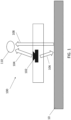
- FIG. 1 shows a typical acoustic playback system 100 located near a wall 10 (or any other audio reflective surface).
- the acoustic playback system 100 includes an audio driver 102.
- the audio driver 102 outputs an audio generally in a first direction 104 towards where the audio driver 102 is facing.
- the audio driver 102 also outputs the audio in a second direction 106 as well (and in fact, many other directions).
- the audio in the second direction 106 can reflect off the wall 10 thus creating a reflected audio 108.
- This reflected audio 108 may be phase shifted due to the delay in time caused by the reflection off the wall 10, which can lead to destructive interference 100 between the audio in the first direction 104 and the reflected audio 108.
- acoustic playback system 100 when acoustic playback system 100 is placed close to a wall 10 of significant proportions this wall 10 will reflect sound (e.g., as reflected audio 108) radiated from the rear of the playback system 100. As most playback systems are approaching omnidirectionality at low frequencies, this radiation towards the wall 10 can be significant. This results in a reflection from the wall 10 that is close to the amplitude of the acoustical signal radiated forward 104 away from the wall 10. These two wavefronts meet 110 and interact with both constructive and destructive interference due to and determined by the delay of the reflected signal 108. This interference causes a so-called comb filtering effect in the entire frequency band where there is significant rearward radiation from the playback system 100.
- the cancellation due to the comb filtering effect can affect some or all of the frequency of the audio in the first direction 104. This can lead to dead spots or incorrect sounding audio to a user at the location where the two wavefronts meet 110. As this is typically in front of the acoustic playback system 100, the effect of the reflected audio can significantly affect the audio quality for a user of the acoustic playback system 100.
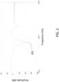
- FIG. 2 shows an amplitude graph of the acoustic playback system of FIG. 1 .
- cancellation (or notch) 202 can occur, for example at the lowest in frequency. For a typical collaboration bar this can be in the range from 400-1000Hz depending on the distance from the wall. The subsequent higher order reflections are typically much less significant due to the increasing directionality of the acoustic playback system.
- FIG. 2 is a based on white noise which is summed with a delayed and low passed filtered version of itself.
- the low pass element is meant to emulate the directionality of the driver while the delay corresponds to the distance to the rear wall times two.
- the downside of known acoustic playback devices is a reduction in general perceived sound quality, speech intelligibility, and even localization. In certification context the product might not pass frequency response limits.
- FIG. 3 illustrates an example embodiment of an acoustic playback system according to the disclosure.
- the disclosed acoustic playback system 300 can reduce and/or eliminate the cancellation that occurs with the system 100 shown in FIG. 1 . Further internal processing can be shown in the embodiments of FIGS. 5-8 .
- the acoustic playback system 300 can include a housing 302.
- the housing has a first side 304 and a second side 306 opposite the first side 304.
- the housing 302 can further include a plurality of walls 306 connecting the first side 304 with the second side 306.
- the acoustic playback system 300 includes at least one amplifier (Shown in FIGS. 5 , 6 , and 8 ) configured to receive an electrical signal representative of an audio and output an amplified audio signal.
- the acoustic playback system 300 can include a primary driver 310.
- the primary driver 310 is configured to receive the amplified audio signal and output a primary audio 312A, 312B, based on the amplified audio signal, form the first side 304.
- the acoustic playback system 300 can include a filler driver 314.
- the filler driver 314 can be configured to receive the amplified audio signal and output a secondary audio 316, based on the amplified audio signal, from the second side 306.
- the filler driver 314 can be an omnidirectional audio source.
- the acoustic playback system 300 can further include a filter (shown in FIGS. 5 , 6 , and 9 ) in communication with the filler driver 316 and configured to apply a filter to the electrical signal and/or the amplified audio signal.
- a filter shown in FIGS. 5 , 6 , and 9 .
- the primary driver 310 output is spaced away from the filler driver 316 output.
- the primary driver 310 can output the primary audio 312A, 312B towards a user (e.g., shown by primary audio 312A), though certain primary audio 312 is directed towards the wall 10. This leads, similar to what is shown in FIG. 1 , to primary reflected audio 320.
- the primary reflected audio 320 may interfere, such as through destructive interference, with the primary audio 312A leading to a cancellation zone 322.
- the acoustic playback system 300 further includes the filler driver 314.
- the filler driver 314 is configured to output secondary audio 316 form the second side 306 of the housing 302. As shown, upon mounting of the acoustic playback system 300, the filler driver 314 is configured to face the wall 10.
- the secondary audio 316 also reflects off of wall 10, which leads to secondary reflected audio 318.
- the filler driver 314 is configured to reduce a comb-filter effect of the primary driver 310.
- the primary audio 312A, 312B and the secondary audio 316 can be the same audio.
- the filler driver 314 and the primary driver 310 can output the same audio.
- the secondary audio 316 can have a lower gain than the primary audio 312A, 312B.
- the filler driver 314 can be configured to add an acoustic signal for the secondary audio 316 into a frequency range where a cancellation of the primary audio 312A, 312B occurs, such as cancellation zone 322.
- the filler driver 314 can also be configured to produce the secondary audio 316 at a same signal as the primary audio 312A, 312B in low frequencies and a different signal as the primary audio 312A, 312B in high frequencies.
- the primary audio 312A, 312B and the secondary audio 316 can be in non-overlapping frequency ranges.
- the acoustic playback system 100 can optionally include at least one microphone 330.
- the at least one microphone 330 can be configured to obtain audio input from the environment.
- the at least one microphone 330 can obtain the primary audio 312A and the secondary audio 316.
- the acoustic playback system 100 can optionally include at least one processor 332.
- the at least one processor 332 can be configured to adjust and/or modify one or more of the components of the acoustic playback system 100.
- the at least one processor 332 can be configured to determine, based on input received from the at least one microphone 330, a position of the acoustical playback system 300 with respect to a wall 10, and wherein the at least one processor 332 is configured to operate the acoustical playback system 300, depending on the position, in an on-wall setting or an away-from-wall setting.
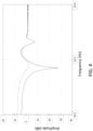
- FIG. 4 shows an amplitude graph of the acoustic playback system of FIG. 3 .
- the solid-line curve simulates the frequency response of an acoustic playback system 300 with the primary driver 310 approximately 130mm from the rear wall 10. In this case it results in a severe cancellation at 700Hz, such as shown in FIG. 2 .
- the dashed-line curve simulates the summed response when the filler driver 314 is placed closer to the wall 10 playing the same signal but low passed. At low frequencies the signals are added in phase resulting in a 6dB higher amplitude while at 700Hz the amplitude is increased more than 20dB. With the added filler driver 314, the acoustic playback system 300 can eliminate the cancellation that occurs by any reflected audio by the wall 10.
- FIG. 5 illustrates an example embodiment of an acoustic playback system according to the disclosure.
- the acoustic playback system 500 of FIG. 5 can include any and/or all of the components of the acoustic playback system 300 of FIG. 3 .
- FIG. 5 illustrates a simplified set of components for convenience.
- the acoustic playback system 500 can include a housing 502.
- the housing can retain at least one amplifier 504 and a filter 506.
- the acoustic playback system 500 can include a primary driver 508 and a filler driver 510.
- the at least one amplifier 504 can receive an electrical signal 520 representative of an audio and can output an amplified audio signal 522.
- the filter 506 receives the amplified audio signal 522 and apply a filter. As shown in FIG. 5 , the filter 506 is associated with the filler driver 510.
- the filter 506 shown in FIG. 5 can be a low-pass filter.
- the filter 506 is a low-pass filter positioned between the at least one amplifier 504 and the filler driver 510.
- a 6dB gain can be achieved at low frequencies if the at least one amplifier 504 can drive it at the same voltage as the primary driver 508.
- the low pass filter 506 can be designed to achieve a minimum of cancellation around the main dip due to potential phase mismatch.
- the filler driver 510 can be identical to the primary driver 508, but this is not necessarily critical as it can be advantageous to provide signal at low frequencies but not necessarily match the primary driver 508.
- the filter 506 of FIG. 5 can be a conditioning filter.
- the filler driver 510 can be a high impedance driver as compared to the primary driver 508.
- the filler driver 510 can have a high Q factor and resonance frequency at the location of any cancellation effect (e.g., dip).
- the filler driver 510 can be placed in parallel with the primary driver 508 without affecting its output significantly.
- the very low damping at the resonance (tuned to the dip-position) will enable it to deliver substantial output at this frequency causing the requested increase in summed amplitude.
- a relatively high impedance driver (filter driver 510) could also be bandpass filtered via filter 510 without needing excessively large filter components, making it feasible to further limit its operating area in frequency to where it is needed.
- the relatively high resonance frequency could be achieved both through driver design and/or by placing it in a relatively small volume.
- FIG. 6 illustrates an example embodiment of an acoustic playback system according to the disclosure.
- the acoustic playback system 600 of FIG. 6 can include any and/or all of the components discussed with respect to acoustic playback system 300 of FIG. 3 .
- the housing 602 can contain the components of the acoustic playback system.
- the acoustic playback system 600 can include a primary amplifier 604 in communication with the primary driver 608 and a filler amplifier 606 in communication with the filler driver 610.
- using an extra amplifier channel can achieve more flexibility in filtering and amplitude matching.
- the filter 603 can be a conditioning filter.
- the filler amplifier 606 is positioning between the filter 603 and the filler driver 610.
- the filter 603 can be an adaptive conditioning filter. As shown, the filter 603 is configured to apply a filter to the electrical signal 620.
- the at least one amplifier 606, 604 is configured to receive the electrical signal (either filtered for filler amplifier 606 or unfiltered for primary amplifier 604) for outputting an amplified audio signal 607A, 607B.
- FIG. 7 illustrates an example embodiment of an acoustic playback system according to the disclosure.
- the acoustic playback system 700 of FIG. 7 can include any and/or all of the components discussed with respect to acoustic playback system 300 of FIG. 3 .
- the housing 702 can contain the components of the acoustic playback system.
- the primary driver 704 can be placed perpendicular to a wall 10. It can be preferably if the primary driver 704 has a substantial size compared to the relevant wavelength.
- the primary driver 704 can be located on the top, bottom or in the side of the acoustic playback system 700. Then the cancellation will occur at a wider frequency band as the speaker diaphragm has varying distance to the rear wall.
- FIG. 8 illustrates an example embodiment of an acoustic playback system according to the disclosure.
- the acoustic playback system 800 of FIG. 8 can include any and/or all of the components discussed with respect to acoustic playback system 300 of FIG. 3 .
- the housing 802 can contain the components of the acoustic playback system 800.
- the at least one amplifier 804 is configured to receive the electrical signal 820 for provision of an amplified audio signal 822.
- the filter can be a primary filter 806 and a filler filter 808, each which receive the amplified audio signal 822.
- the primary filter 806 can be a high pass filter in communication with the primary driver 810.
- the filler filter 808 can be a low pass filter in communication with the filler driver 812.
- the filters 806, 808 could just as well be implemented on line-level signals prior to two separate amplifier channels or in a digital signal processor.
- FIG. 9 shows cancellation effects of an example embodiment of an acoustic playback system shown in FIG. 8 .
- each of the drivers can have their own frequency range, such as through the use of a filter 806, 808 for each of the primary driver 810 and the filler driver 812.
- Line 902 illustrates the low-passed filler driver 812 and line 904 illustrates the high-passed primary driver 810.
- the acoustic playback system 300, 500, 600, 700, 800 can be sound bar, a speaker, a video bar, a loudspeaker, and a subwoofer.
Landscapes
- Health & Medical Sciences (AREA)
- Otolaryngology (AREA)
- Physics & Mathematics (AREA)
- Engineering & Computer Science (AREA)
- Acoustics & Sound (AREA)
- Signal Processing (AREA)
- General Health & Medical Sciences (AREA)
- Circuit For Audible Band Transducer (AREA)
Priority Applications (1)
| Application Number | Priority Date | Filing Date | Title |
|---|---|---|---|
| EP23204816.5A EP4456560A1 (de) | 2023-10-20 | 2023-10-20 | Akustisches wiedergabesystem mit verbesserter unterdrückungskompensation |
Applications Claiming Priority (1)
| Application Number | Priority Date | Filing Date | Title |
|---|---|---|---|
| EP23204816.5A EP4456560A1 (de) | 2023-10-20 | 2023-10-20 | Akustisches wiedergabesystem mit verbesserter unterdrückungskompensation |
Publications (1)
| Publication Number | Publication Date |
|---|---|
| EP4456560A1 true EP4456560A1 (de) | 2024-10-30 |
Family
ID=88507010
Family Applications (1)
| Application Number | Title | Priority Date | Filing Date |
|---|---|---|---|
| EP23204816.5A Withdrawn EP4456560A1 (de) | 2023-10-20 | 2023-10-20 | Akustisches wiedergabesystem mit verbesserter unterdrückungskompensation |
Country Status (1)
| Country | Link |
|---|---|
| EP (1) | EP4456560A1 (de) |
Citations (2)
| Publication number | Priority date | Publication date | Assignee | Title |
|---|---|---|---|---|
| US20060269069A1 (en) * | 2005-05-31 | 2006-11-30 | Polk Matthew S Jr | Compact audio reproduction system with large perceived acoustic size and image |
| US20150222994A1 (en) * | 2009-10-05 | 2015-08-06 | Harman International Industries, Inc. | Multichannel audio system having audio channel compensation |
-
2023
- 2023-10-20 EP EP23204816.5A patent/EP4456560A1/de not_active Withdrawn
Patent Citations (2)
| Publication number | Priority date | Publication date | Assignee | Title |
|---|---|---|---|---|
| US20060269069A1 (en) * | 2005-05-31 | 2006-11-30 | Polk Matthew S Jr | Compact audio reproduction system with large perceived acoustic size and image |
| US20150222994A1 (en) * | 2009-10-05 | 2015-08-06 | Harman International Industries, Inc. | Multichannel audio system having audio channel compensation |
Similar Documents
| Publication | Publication Date | Title |
|---|---|---|
| US8401202B2 (en) | Speakers with a digital signal processor | |
| JP4171468B2 (ja) | ラウドスピーカ列システム | |
| US7804972B2 (en) | Method and apparatus for calibrating a sound beam-forming system | |
| WO2007127762A2 (en) | Method and system for sound beam- forming using internal device speakers in conjunction with external speakers | |
| KR19990036009A (ko) | 음향 교정 장치 | |
| EP3163903B1 (de) | Akustischer prozessor für eine mobile vorrichtung | |
| WO1998056208A2 (en) | Cabin communication system | |
| WO2018158558A1 (en) | Device for capturing and outputting audio | |
| EP1901582B1 (de) | Audioeinrichtung und audiostrahl-steuerverfahren | |
| JP2021007215A (ja) | アンバランスな空気チャンバーを備える、バランスが取れたステレオヘッドホン | |
| US8923531B2 (en) | Speaker with frequency directed dual drivers | |
| EP4456560A1 (de) | Akustisches wiedergabesystem mit verbesserter unterdrückungskompensation | |
| EP1552719B1 (de) | Verzögerungsnetzwerkmikrofone mit harmonischer vernestung | |
| US20050286727A1 (en) | Apparatus for expanding sound image upward | |
| JP3992974B2 (ja) | スピーカー装置 | |
| JP2003264895A (ja) | スピーカー装置 | |
| US11523210B1 (en) | Omnidirectional speaker with inverted dome diaphragm and separate exits | |
| US12413895B2 (en) | Loudspeaker assembly and hand-held device | |
| CN107517355B (zh) | 一种电视机 | |
| CN222706602U (zh) | 一种耳机 | |
| JPH11239400A (ja) | スピーカー装置 | |
| EP4478735A1 (de) | Kopfhörer | |
| KR100756049B1 (ko) | 오디오기기용 음향재생 방법 및 장치 | |
| JP2013073016A (ja) | 音響再生装置 | |
| JPH10108293A (ja) | 車載用スピーカシステム |
Legal Events
| Date | Code | Title | Description |
|---|---|---|---|
| PUAI | Public reference made under article 153(3) epc to a published international application that has entered the european phase |
Free format text: ORIGINAL CODE: 0009012 |
|
| STAA | Information on the status of an ep patent application or granted ep patent |
Free format text: STATUS: THE APPLICATION HAS BEEN PUBLISHED |
|
| AK | Designated contracting states |
Kind code of ref document: A1 Designated state(s): AL AT BE BG CH CY CZ DE DK EE ES FI FR GB GR HR HU IE IS IT LI LT LU LV MC ME MK MT NL NO PL PT RO RS SE SI SK SM TR |
|
| STAA | Information on the status of an ep patent application or granted ep patent |
Free format text: STATUS: THE APPLICATION HAS BEEN WITHDRAWN |
|
| 18W | Application withdrawn |
Effective date: 20241104 |