EP4456500A1 - Kommunikationsvorrichtung zur unterstützung von ip-basiertem rapsienet und netzwerksystem damit - Google Patents
Kommunikationsvorrichtung zur unterstützung von ip-basiertem rapsienet und netzwerksystem damit Download PDFInfo
- Publication number
- EP4456500A1 EP4456500A1 EP22911553.0A EP22911553A EP4456500A1 EP 4456500 A1 EP4456500 A1 EP 4456500A1 EP 22911553 A EP22911553 A EP 22911553A EP 4456500 A1 EP4456500 A1 EP 4456500A1
- Authority
- EP
- European Patent Office
- Prior art keywords
- communication device
- communication
- data
- rapienet
- interface
- Prior art date
- Legal status (The legal status is an assumption and is not a legal conclusion. Google has not performed a legal analysis and makes no representation as to the accuracy of the status listed.)
- Pending
Links
Images


Classifications
-
- H—ELECTRICITY
- H04—ELECTRIC COMMUNICATION TECHNIQUE
- H04L—TRANSMISSION OF DIGITAL INFORMATION, e.g. TELEGRAPHIC COMMUNICATION
- H04L69/00—Network arrangements, protocols or services independent of the application payload and not provided for in the other groups of this subclass
- H04L69/22—Parsing or analysis of headers
-
- H—ELECTRICITY
- H04—ELECTRIC COMMUNICATION TECHNIQUE
- H04L—TRANSMISSION OF DIGITAL INFORMATION, e.g. TELEGRAPHIC COMMUNICATION
- H04L45/00—Routing or path finding of packets in data switching networks
- H04L45/02—Topology update or discovery
- H04L45/04—Interdomain routing, e.g. hierarchical routing
-
- H—ELECTRICITY
- H04—ELECTRIC COMMUNICATION TECHNIQUE
- H04L—TRANSMISSION OF DIGITAL INFORMATION, e.g. TELEGRAPHIC COMMUNICATION
- H04L12/00—Data switching networks
- H04L12/28—Data switching networks characterised by path configuration, e.g. LAN [Local Area Networks] or WAN [Wide Area Networks]
- H04L12/44—Star or tree networks
-
- H—ELECTRICITY
- H04—ELECTRIC COMMUNICATION TECHNIQUE
- H04L—TRANSMISSION OF DIGITAL INFORMATION, e.g. TELEGRAPHIC COMMUNICATION
- H04L12/00—Data switching networks
- H04L12/28—Data switching networks characterised by path configuration, e.g. LAN [Local Area Networks] or WAN [Wide Area Networks]
- H04L12/46—Interconnection of networks
-
- H—ELECTRICITY
- H04—ELECTRIC COMMUNICATION TECHNIQUE
- H04L—TRANSMISSION OF DIGITAL INFORMATION, e.g. TELEGRAPHIC COMMUNICATION
- H04L45/00—Routing or path finding of packets in data switching networks
- H04L45/02—Topology update or discovery
-
- H—ELECTRICITY
- H04—ELECTRIC COMMUNICATION TECHNIQUE
- H04L—TRANSMISSION OF DIGITAL INFORMATION, e.g. TELEGRAPHIC COMMUNICATION
- H04L45/00—Routing or path finding of packets in data switching networks
- H04L45/302—Route determination based on requested QoS
- H04L45/306—Route determination based on the nature of the carried application
-
- H—ELECTRICITY
- H04—ELECTRIC COMMUNICATION TECHNIQUE
- H04L—TRANSMISSION OF DIGITAL INFORMATION, e.g. TELEGRAPHIC COMMUNICATION
- H04L45/00—Routing or path finding of packets in data switching networks
- H04L45/80—Ingress point selection by the source endpoint, e.g. selection of ISP or POP
- H04L45/85—Selection among different networks
-
- H—ELECTRICITY
- H04—ELECTRIC COMMUNICATION TECHNIQUE
- H04L—TRANSMISSION OF DIGITAL INFORMATION, e.g. TELEGRAPHIC COMMUNICATION
- H04L12/00—Data switching networks
- H04L12/64—Hybrid switching systems
- H04L12/6418—Hybrid transport
- H04L2012/6432—Topology
- H04L2012/644—Star
Definitions
- the present invention relates to a communication device supporting IP-based RAPIEnet and a network system including the same.
- RAPIEnet Real-time Automation Protocols for Industrial Ethernet
- IEC 61158-3 type 21, IEC 61158-4 type 21, IEC 61158-5 type 21, IEC 61158-6 type 21, and IEC 62439-7 refers to an Ethernet-based high-availability industrial network protocol that supports ring topology or line topology.
- each communication device manages network-wide information in a network information base (NIB, IEC 62439-7 4.5) based on a hop count.
- NNB network information base
- the hop count can be calculated only when the frame for managing the network can be understood between communication devices, and in order to perform functions such as searching for an optimal transmission path without knowing how the network is connected, all communication devices on the network must be able to support RAPIEnet.
- An object of the present invention is to provide a communication device and a network system including the same that is capable of operating a RAPIEnet-based application even in a star or tree-shaped network topology using a general-purpose Ethernet switch.
- An object of the present invention is to provide a communication device and a network system including the same that allows generic communication devices that cannot implement the RAPIEnet Data Link layer for RAPIEnet communication to transmit and receive data using the RAPIEnet application.
- a communication device comprises: a communicator; and a processor configured to: if a network composed of a first topology including a star topology or a line topology is included on a communication path connecting the communication device and the other communication device, configure data to be transmitted to the other communication device through a first interface for accessing a RAPIEnet (Real-time Automation Protocol for Industrial Ethernet)-based upper layer and an Internet Protocol (IP)-based lower layer, and transmit the data to the other communication device through the communicator using the communication path.
- RAPIEnet Real-time Automation Protocol for Industrial Ethernet
- IP Internet Protocol
- the data may be first data
- the processor may be configured to: if the network composed of the first topology is not included on the communication path, select one of the first interface, or a second interface for accessing the RAPIEnet-based upper layer and the RAPIEnet-based lower layer, configure second data to be transmitted to the other communication device through the selected first interface or the second interface, and transmit the data to the other communication device through the communicator using the communication path.
- the data may be first data
- the processor may be configured to: identify header information included in third data received from the other communication device, and if the header information includes header information about the first interface, receive the third data through the first interface.
- the processor may be configured to configure the data to include header information about the first interface.
- the header information may include Destination Address, Source Address, Destination SAP (Service Access Point), Source SAP, Extension Data area, and Group Data area.
- a network system comprises: a plurality of communication devices including a first communication device and a second communication device, wherein the first communication device comprises: a first communicator; and a first processor configured to: if a network composed of a first topology including a star topology or a line topology is included on a communication path connecting the first communication device and the second communication device, configure data to be transmitted to the second communication device through a first interface for accessing a RAPIEnet (Real-time Automation Protocol for Industrial Ethernet)-based upper layer and an Internet Protocol (IP)-based lower layer, and transmit the data to the second communication device using the communication path through the first communicator, and the second communication device comprises: a second communicator; and a second processor configured to: identify header information included in the data received from the first communication device, and if the header information includes header information about the first interface, receive the data through the first interface.
- RAPIEnet Real-time Automation Protocol for Industrial Ethernet
- IP Internet Protocol
- the first processor may be configured to configure the data to include header information about the first interface.
- the network system may further include at least one Ethernet switch on a communication path connecting the first communication device and the second communication device.
- a communication device of a first communication method using a data link layer based on multiple Ethernet ports is capable of communicating with other communication device in a second communication method using a data link layer based on a single Ethernet port.
- the first communication method and the second communication method may be connectionless communication methods.
- the first communication method may be RAPIEnet communication
- the second communication method may be UDP/IP communication.
- the communication device may communicate using header information necessary for the second communication method.
- the communication device may communicate with the other communication device in the second communication method.
- the communication device may attempt communication in the second communication method.
- the communication device may communicate with the other communication device in the first communication method or the second communication method selected by a user input.
- a network-based control system can be configured according to various field situations by allowing RAPIEnet-based applications to be used even in a network configured in a star or tree topology.
- generic communication devices that do not implement the RAPIEnet Data Link layer for RAPIEnet communication can also transmit and receive data using the RAPIEnet application, thereby providing flexibility in network configuration.
- the RAPIEnet application can be used without modifying even in a network constituting a topology that may not perform existing RAPIEnet communication, which is efficient and economical.
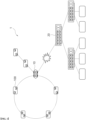
- FIG. 1 is a diagram illustrating a network system composed of a plurality of communication devices supporting RAPIEnet.
- FIG. 1 is an example of a network system 1, in which a plurality of communication devices 100 form a network through a combination of ring topology, line topology, and tree topology, and shows a RAPIEnet ring switch 10 that connects a network in a ring topology and a network in a line topology, and a general-purpose Ethernet switch 20 that connects a network in a ring topology and a network in a tree topology.
- RAPIEnet which is configured using two physical layers, it can only be applied to networks of ring topology or line topology. Therefore, RAPIEnet communication may be performed using the RAPIEnet ring switch 10 supporting the RAPIEnet protocol in a control field in which a network may be configured only with a star topology or a tree topology (hereinafter referred to as a first topology).
- a first topology a star topology or a tree topology
- the ring switch 10 it is not suitable for configuring multiple topologies through ring switches 10 due to the limitation of the number of ports that can be accommodated, and the ring switch 10 itself is expensive, making it difficult to apply.
- RAPIEnet which is currently applied to the industrial domain, it is configured to exclude the UDP/IP layer and communicate directly from the RAPIEnet Data Link layer to the application layer so that timing is fast and real-time scheduling is possible according to industrial control. Therefore, the general-purpose Ethernet switch 20, which understands the UDP/IP frame but does not understand the RAPIEnet protocol, cannot be used.
- the general-purpose Ethernet switch 20 connected to the ring switch 10 does not understand the RAPIEnet protocol, so communication devices configured in a tree topology may not communicate with communication devices configured in a ring or line topology.
- the first communication method may be RAPIEnet communication
- the second communication method may be UDP/IP communication
- the first communication method and the second communication method are connectionless communication methods.
- a RAPIEnet network can be configured in the form of a star or tree using a cheap and easy-to-use general-purpose Ethernet switch.
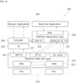
- FIG. 2 is a diagram illustrating a RAPIEnet protocol stack according to an embodiment of the present invention.
- the protocol stack 200 shown in FIG. 2 represents a protocol transmission path when the operating application is a generic application, that is, a RAPIEnet application (real-time application).
- the protocol stack 200 includes a physical layer 210, a RAPIEnet Data Link layer 220, an IP layer 230, a TCP/UDP layer 240, a RAPIEnet Application layer 250, and an Application layer 260.
- the physical layer 210 refers to a physical area that bits and transmits data such as frames or packets from one node to an adjacent node, and is an area defining a protocol related to network standards such as LAN, WAN, and MAN.
- a communication device supporting RAPIEnet has two ports.
- the RAPIEnet Data Link layer 220 obtains and manages information on the optimal path and network shape configuration between communication devices by calculating a hop to each communication device through a negotiation process.
- data is transmitted and received through a real time-queue (RT-Q) 221 having a high scheduling priority.
- RT-Q real time-queue
- the RAPIEnet Data Link layer 220 may be a data link layer based on multiple Ethernet ports.
- the IP layer 230 is a layer that determines which path to go through to send data to a desired communication device, similar to the RAPIEnet Data Link layer 220. At this time, it is shown that the IP layer 230 also goes through the RAPIEnet Data Link layer 220 in the protocol stack 200, but in the process of transmitting the data from the actual IP layer 230 to the physical layer 210 through the NRT-Q (Non Real Time-Q) 222, it is not modified and transmitted to the physical layer 210 as it is. That is, there is no interdependence between the IP layer 230 and the RAPIEnet Data Link layer 220. However, the IP layer 230 manages a table that determines which port in the physical layer 210 to transmit and receive data based on the address management system called the MAC address 223 of the RAPIEnet Data Link layer 220.
- the TCP/UDP layer 240 is an area defining a method of transmitting data.
- the connection between communication devices is established and maintained while data is transmitted and received in a connection-oriented manner, so reliability is guaranteed.
- the UDP layer unlike TCP, since it does not go through the process of dividing and reassembling data into packets, the data transmission speed is fast, and when data is transmitted and received in a connectionless manner, it transmits and receives data unilaterally without going through a signal processing procedure to transmit or receive data.
- the message communication method of RAPIEnet uses a connectionless protocol rather than a connection-oriented protocol. Therefore, in the present invention, UDP, a connectionless protocol type, is used to access the IP layer. Through this, since the UDP header is attached to the data for using the RAPIEnet application, a network of the first topology may be configured using a general-purpose Ethernet switch.
- the RAPIEnet Application layer 250 is a data transmission layer similar to the TCP/UDP layer 240, and the RAPIEnet Application layer 250 has a RAPIEnet DL interface (RAPIEnet DL I/F) 251 and a UDP interface (UDP I/F) 252 to access the upper and lower layers.
- the RAPIEnet Application layer 250 may select one of the two interfaces to transmit and receive data.
- the communication path of the RAPIEnet application may implement two paths.
- One is a general RAPIEnet communication method, and is a path that transmits data to the RAPIEnet Data Link layer 220 through the RAPIEnet DL interface 251 or receives data entering the RAPIEnet Data Link layer 220 through the RAPIEnet DL interface 251.
- the other is a transmission path to the IP layer 230 to be implemented in the present invention, through the UDP interface 252 to communicate with the IP layer 230.
- the communication device 100 When communication fails by first attempting communication with another communication device in the first communication method, which is RAPIEnet communication, the communication device 100 according to an embodiment of the present invention may attempt communication in the second communication method, which is UDP/IP communication. In addition, it is not limited to this, and it is possible to communicate with other communication devices in the first communication method or the second communication method selected by user input.
- the reason why the UDP interface 252 is used rather than the TCP interface is that the RAPIEnet uses a connectionless protocol as described above in the TCP/UDP layer 240.
- the data passes through the UDP interface 252 of the RAPIEnet Application layer 250, the data includes header information about the UDP interface.
- the TCP/UDP layer 240 may identify the RAPIEnet Application data.
- header information necessary for the second communication method may be attached to RAPIEnet-based data to communicate with each other. Details of header information about the UDP interface will be described with reference to FIG. 4 .
- the Application layer 260 is a layer defining a service for transmitting or receiving data between transmission and reception sides, and includes a generic application and a RAPIEnet application.
- RAPIEnet applications include, for example, data write/read functions in client/server models, data input/output functions in master/slave models, data sharing functions in producer/consumer models, remote OS download functions, and applications that perform various diagnostic functions.
- the RAPIEnet application is characterized by having to operate at a predictable time, in the case of a generic application, the viewpoint for the operation may not be predicted. Therefore, the RAPIEnet application is used when real-time control operation of the application is required, as in the automobile production work site due to the sequential movement of the conveyor belt.
- the RAPIEnet application of the Application layer 260 may communicate via the RAPIEnet Data Link layer 220 through the RAPIEnet DL interface 251 of the RAPIEnet Application layer 250, and communicate via UDP/IP through the UDP interface 252.
- a general-purpose Ethernet switch may understand the UDP protocol, so a RAPIEnet network of a tree or star topology may be configured using a general-purpose Ethernet switch.
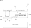
- FIG. 3 is a diagram illustrating a RAPIEnet protocol stack according to an embodiment of the present invention.
- the protocol stack 300 shown in this drawing has removed the RAPIEnet Data Link layer 220.
- the IP layer 320, the TCP/UDP layer 330, and the Application layer 350 have the same role and function as the layers of the protocol stack 200 of FIG. 2 , and thus will be understood with reference to them.
- the protocol stack 300 of FIG. 3 may be applied to a communication device that does not implement the RAPIEnet Data Link layer 220.
- a hardware configuration to implement the functions of RT-Q 221 and NRT-Q 222 is required.
- communication devices that are difficult to implement this hardware configuration such as embedded devices such as PCs and human machine interfaces (HMI), that can only perform conventional communication, do not implement the RAPIEnet Data Link layer 220.
- HMI human machine interfaces
- the generic communication device may communicate with the RAPIEnet application of the Application layer 350 via the UDP interface 341 of the RAPIEnet Application layer 340 through the Ethernet MAC 310, the IP layer 320, and the UDP layer 330.
- generic communication devices that do not implement the RAPIEnet Data Link layer 220 for RAPIEnet communication may also transmit and receive data using the RAPIEnet application through the UDP interface 341, thereby providing flexibility in network configuration.
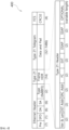
- FIG. 4 is a diagram illustrating header information 400 regarding a UDP interface according to an embodiment of the present invention.
- the RAPIEnet application may select an effective communication method by utilizing various functions of the RAPIEnet Data Link layer. Since the RAPIEnet application utilizes various transmission functions of the RAPIEnet Data Link layer, header information must be added to the UDP interface.
- the header information includes six items: 1) Destination Address (according to the RAPIEnet standard), 2) Source Address (according to the RAPIEnet standard), 3) Destination SAP (Service Access Point) (according to the RAPIEnet standard), 4) Source SAP (according to the RAPIEnet standard), 5) Extension Data area (according to the RAPIEnet standard), and 6) Group Data area (according to the RAPIEnet standard).
- each item will be examined in detail with reference to Table 1 indicating values and explanations.
- This field represents the destination address of the node to which the frame is transmitted.
- the destination address of the message can be set from 0x0000 to 0xFFFF as shown in [Table 1]. If the destination address is 0xFF, the destination MAC address field contains the ISO/IEC/IEEE 8802 3 MAC address.
- This field represents the source address of the node where the frame is created.
- This field represents the SAP of the DLE through which DLPDU is transmitted, and the range of allowable values is 0 to 65535.
- This field represents the SAP of the DLE where DLPDU is generated, and the range of allowable values is 0 to 65535.
- This field exists when the VoE bit in the frame control field is set to TRUE.
- Group Mask Enable is a bit field that specifies whether the peer device will accept a frame when the frame is broadcast or multicast. If the value is set to TRUE, the Group Mask is activated in the peer device that receives the frame.
- the Group Mask field uses a bit sequence to indicate message reception selection.
- Group Mask Enable is set to TRUE, the Group Mask field is added in 4-octet increments (e.g., 4, 8, 12 to 32 octets).
- Each bit represents a reception selection of a frame for a corresponding DL entity identifier. 1 means TRUE for frame reception and 0 means FALSE.
- the first bit represents the frame reception option for the top DL entity identifier.
- the extension type field represents the type of the extension field.
- a value of 0x00 indicates an invalid extension type, other values are reserved for later use.
- the extension length field represents the length of the extension field.
- the extension length specifies the length of the Group Mask field.
- the extension length specifies the length of the extension field.
- the first two octets specify the length of the Group Mask field and the next two octets specify the extension type.
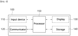
- FIG. 5 is a block diagram illustrating a configuration of a communication device 100 according to an embodiment of the present invention.
- the input device 110 includes at least one port connecting the communication device 100 to another communication device, the RAPIEnet ring switch 10, or the general-purpose Ethernet switch 20, or the like.
- the input device 110 includes at least one input means for generating input data in response to a user input.
- the input device 110 may include an input terminal, a button, a rotary switch, a keypad, a dome switch, a touch panel, a jog shuttle, a touch key, and the like.
- the communicator 120 performs communication with external devices such as other communication devices and external servers (not shown). To this end, the communicator 120 may perform wireless communication such as 5th Generation communication (5G), Long Term Evolution-Advanced (LTE-A), Long Term Evolution (LTE), and Wireless Fidelity (Wi-Fi).
- the communicator 120 may use wireless communication such as RF (radio frequency), Zigbee, Bluetooth, Wi-Fi, UWB (Ultra Wide Band), and NFC (Near Field Communication) as a communication method.
- the communicator 120 may be implemented as a wireless communication module that performs wireless communication with an AP, such as Wi-Fi, or a wireless communication module that performs one-to-one direct wireless communication, such as Bluetooth.
- the display 130 displays display data related to the operation of the communication device 100.
- the display 130 includes a liquid crystal display (LCD), a light emitting diode (LED) display, an organic light emitting diode (OLED) display, a micro electro mechanical systems (MEMS) display, and an electronic paper display.
- the display 130 may be combined with the input device 110 to be implemented as a touch screen.
- the storage 140 stores operation programs of the communication device 100.
- the storage 140 includes a non-volatile storage for storing data regardless of whether power is supplied or not, and a volatile memory in which data to be processed by the processor 150 is loaded and cannot retain data unless power is provided.
- the storage includes a flash memory, a hard-disc drive (HDD), a solid-state drive (SSD), a read only memory (ROM), and the like, and the memory includes a buffer and a random access memory (RAM), and the like.
- the processor 150 may execute software, such as a program, to control at least one other component (e.g., hardware or software component) of the communication device 100 connected to the processor 150, and may perform various data processing or calculations.
- software such as a program
- the processor 150 may configure data to be transmitted to another communication device through a UDP interface based on a network configuration on a communication path connecting the communication device 100 and the other communication device, and may perform an operation of transmitting data to another communication device using a communication path through the communicator 120.
- the processor 150 may perform an operation of identifying header information included in data received from another communication device, and receiving data through the UDP interface when the identified header information includes header information about the UDP interface.
- FIG. 6 is a diagram illustrating a network system 600 composed of a plurality of communication devices supporting RAPIEnet according to an embodiment of the present invention.
- the network system 600 is composed of a ring topology network and a tree topology network, and the two networks are connected by a ring switch 10 and a general-purpose Ethernet switch 20 connected to the ring switch 10.
- a first communication device 101 included in the ring topology network and a second communication device 102 included in the tree topology network is performed.
- the first communication device 101 and the second communication device 102 are one of the communication devices 100 described above with reference to the description of FIG. 5 , and the configuration included in each communication device is understood with reference to the description of FIG. 5 .
- the first communication device 101 communicates using the protocol stack 200 of FIG. 2 as configuring a ring topology, which is one of the RAPIEnet networks.
- the protocol stack 200 of FIG. 2 may be used as a communication device supporting RAPIEnet, but the present invention is not limited thereto, and in the case of a communication device performing general IP communication, the protocol stack 300 of FIG. 3 may be used. That is, the second communication device 102 is a communication device constituting a tree topology network, and does not necessarily have to be a RAPIEnet communication device having two physical ports.
- the data When a network configured with at least one topology of a star topology and a tree topology is included on a communication path connecting the first communication device 101 and the second communication device 102, the data must access the IP layer 230. That is, in order to transmit and receive data to and from a communication device on a star topology or tree topology, it must be through a general-purpose Ethernet switch, and the general-purpose Ethernet switch can understand the IP-based protocol, so it is necessary to modify the data transmission protocol for this.
- the first processor 151 of the first communication device 101 may access a RAPIEnet-based upper layer to receive data entering the IP layer 230, and may use the UDP interface 252, which is a first interface capable of accessing an IP-based lower layer to transmit RAPIEnet-based data with an IP-based protocol.
- the UDP interface 252 may exist in the RAPIEnet Application layer 250.
- the RAPIEnet-based upper layer means the RAPIEnet Application layer 250 and the Application layer 260
- the IP-based lower layer means the TCP/UDP layer 240 or less.
- the RAPIEnet DL interface 251 which is the second interface for accessing the RAPIEnet-based upper layer and the RAPIEnet-based lower layer, may be used.
- the first processor 151 of the first communication device 101 may select one of the RAPIEnet DL interface 251 and the UDP interface 252 to transmit data in order to access a lower layer in the RAPIEnet Application layer 250 of the protocol stack 200.
- the first processor of the first communication device 101 may configure data to be transmitted to the second communication device 102 through the UDP interface 252 based on a communication path with the second communication device 102.
- the first processor 150 of the first communication device 101 may determine whether a route through the UDP interface 252 should be selected by identifying the presence or absence of the general-purpose Ethernet switch 20 on the communication path.
- the data configured through the UDP interface 252 includes header information about the UDP interface described above with reference to FIG. 4 .
- the first processor 151 of the first communication device 101 may transmit RAPIEnet-based data including header information about the UDP interface 252 to the second communication device 102 along a communication path with the second communication device 102.
- the second processor 152 of the second communication device 102 identifies header information included in data received from the first communication device 101.
- the identified header information includes header information about the UDP interface 252
- the second communication device 102 receives data through the UDP interface 252.
- the second communication device 102 receives data using the UDP interface 252 of the RAPIEnet Application layer 250 via the IP layer 230 and TCP/UDP layer through the NRT-Q 222 of the RAPIEnet Data Link layer 220 and the TCP/UDP layer 240.
- the second communication device 102 is a device that performs general IP communication, such as a PC or embedded device, as described above, it may communicate with the RAPIEnet application of the Application layer 350 through the UDP interface 341 of the RAPIEnet Application layer 340 through the MAC layer 310, the IP layer 320, and the UDP layer 330 using the protocol stack 300 of FIG. 3 .
- the RAPIEnet application may be used without modifying even in a network constituting a topology that may not perform existing RAPIEnet communication, resources required for application development are not required at all.
- even communication devices that do not support RAPIEnet communication can use the RAPIEnet application without having to modify the RAPIEnet application, which is economical.
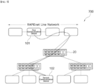
- FIG. 7 is a diagram illustrating a network system 700 composed of a plurality of communication devices supporting RAPIEnet according to another embodiment of the present invention.
- the network system 700 is composed of a line topology network and a tree topology network, and the two networks are connected by a general-purpose Ethernet switch 20.
- a first communication device 101 included in the line topology network and a second communication device 102 included in the tree topology network is performed.
- the first communication device 101 and the second communication device 102 are one of the communication devices 100 described above with reference to the description of FIG. 5 , and the configuration included in each communication device is understood with reference to the description of FIG. 5 .
- the first communication device 101 communicates using the protocol stack 200 of FIG. 2 as configuring a line topology, which is one of the RAPIEnet networks.
- FIG. 7 the situation is the same except that there is only a difference in that the FIG. 6 and the network including the first communication device 101 is a line topology and a ring topology, respectively. Therefore, overlapping points are omitted and additional contents are mentioned. The same is true that the content may be supplemented and applied to the network system 600 of FIG. 6 .
- the line network manager may be a communication device located at both ends of the four communication devices.
- the line network manager allows communication devices to transmit and receive RAPIEnet-based data only within the line network. This is because when the RAPIEnet protocol is transmitted to a general-purpose Ethernet switch 20, the general-purpose Ethernet switch 20 does not understand it, so the switch may be broken or malfunctioned. Therefore, the line network manager only transmits data including IP-based protocols, that is, data including header information about UDP interfaces 252 and 341, to the general-purpose Ethernet switch 20.
- the first communication device 101 which is the client side that starts data communication, may have information in advance on which interface to use for transmitting data among the RAPIEnet DL interface 251 and the UDP interface 252. This may exist in the form of a communication parameter on the client side, and may be set by a communication user (technician).
- the second communication device 102 which is a server-side communication device, responds to data requested by the client, since it is possible to distinguish which of the RAPIEnet DL interface 251 and the UDP interface 252 has received data based on the header information included in the received data, the corresponding interface may be responded using this information.
- FIG. 8 is a diagram illustrating a network system 800 composed of a plurality of communication devices supporting RAPIEnet according to yet another embodiment of the present invention.
- the network system 800 is composed of a tree topology network, and communication devices are connected by a general-purpose Ethernet switch 20. In the present embodiment, it is confirmed that communication between a first communication device 101 and a second communication device 102 included in the tree topology network is performed.
- the first communication device 101 and the second communication device 102 are one of the communication devices 100 described above with reference to the description of FIG. 5 , and the configuration included in each communication device is understood with reference to the description of FIG. 5 .
- the protocol stack 200 of FIG. 2 may be used as a communication device supporting RAPIEnet, but the present invention is not limited thereto, and in the case of a communication device performing general IP communication, the protocol stack 300 of FIG. 3 may be used. That is, the first communication device 101 and the second communication device 102 are communication devices constituting a tree topology network, and do not necessarily have to be a RAPIEnet communication device having two physical ports.
- the first processor 151 of the first communication device 101 identifies a communication path connecting the first communication device 101 and the second communication device 102 to communicate with the second communication device 102.
- the first processor 151 of the first communication device 101 may use the UDP interface 252, which is the first interface capable of accessing the RAPIEnet-based upper layer and accessing the IP-based lower layer.
- the first communication device 101 may access the RAPIEnet-based upper layer and the IP-based lower layer using the UDP interface 341 of the protocol stack 300 of FIG. 3 .
- the second processor 152 of the second communication device 102 identifies header information included in data received from the first communication device 101. When the identified header information includes header information about the UDP interface 252, the second communication device 102 receives data through the UDP interface 252. If the second communication device 102 is a device that performs general IP communication such as a PC or an embedded device, it may perform communication through the UDP interface 341 of the protocol stack 300 of FIG. 3 .
- IP-based RAPIEnet communication is possible even between communication devices in which the RAPIEnet Application layer for RAPIEnet communication is not implemented.
Landscapes
- Engineering & Computer Science (AREA)
- Computer Networks & Wireless Communication (AREA)
- Signal Processing (AREA)
- Computer Security & Cryptography (AREA)
- Small-Scale Networks (AREA)
Applications Claiming Priority (2)
| Application Number | Priority Date | Filing Date | Title |
|---|---|---|---|
| KR1020210186922A KR102539612B1 (ko) | 2021-12-24 | 2021-12-24 | IP 기반 RAPIEnet을 지원하는 통신 디바이스 및 이를 포함하는 네트워크 시스템 |
| PCT/KR2022/015771 WO2023120914A1 (ko) | 2021-12-24 | 2022-10-17 | Ip 기반 rapienet을 지원하는 통신 디바이스 및 이를 포함하는 네트워크 시스템 |
Publications (2)
| Publication Number | Publication Date |
|---|---|
| EP4456500A1 true EP4456500A1 (de) | 2024-10-30 |
| EP4456500A4 EP4456500A4 (de) | 2026-01-14 |
Family
ID=86755414
Family Applications (1)
| Application Number | Title | Priority Date | Filing Date |
|---|---|---|---|
| EP22911553.0A Pending EP4456500A4 (de) | 2021-12-24 | 2022-10-17 | Kommunikationsvorrichtung zur unterstützung von ip-basiertem rapsienet und netzwerksystem damit |
Country Status (6)
| Country | Link |
|---|---|
| US (1) | US12513075B2 (de) |
| EP (1) | EP4456500A4 (de) |
| JP (1) | JP7748543B2 (de) |
| KR (1) | KR102539612B1 (de) |
| CN (1) | CN117501672A (de) |
| WO (1) | WO2023120914A1 (de) |
Family Cites Families (13)
| Publication number | Priority date | Publication date | Assignee | Title |
|---|---|---|---|---|
| US5537417A (en) | 1993-01-29 | 1996-07-16 | International Business Machines Corporation | Kernel socket structure for concurrent multiple protocol access |
| MX2007008112A (es) * | 2004-12-31 | 2007-10-19 | British Telecomm | Metodo para ejecutar una red sin conexion como una red de conexion orientada. |
| US20120014395A1 (en) | 2009-04-07 | 2012-01-19 | Mitsubishi Electric Corporation | Communication adapter apparatus |
| EP3261294B1 (de) * | 2010-06-08 | 2019-12-04 | Avago Technologies International Sales Pte. Limited | Spiegelung eines entfernten ports mit trill |
| JP5912923B2 (ja) | 2012-06-29 | 2016-04-27 | アズビル株式会社 | リング/スター型イーサネットシステム、リング/スター型スイッチ、およびフレーム転送制御方法 |
| EP2713563B1 (de) * | 2012-09-28 | 2017-08-02 | Siemens Aktiengesellschaft | Redundant betreibbares industrielles Kommunikationssystem, Kommunikationsgerät und Verfahren zum redundanten Betrieb eines industriellen Kommunikationssystems |
| US9100294B2 (en) * | 2013-01-30 | 2015-08-04 | Rockwell Automation Technologies, Inc. | Network configurable industrial device |
| EP2988451A1 (de) * | 2014-08-22 | 2016-02-24 | Vodafone IP Licensing limited | Verfahren und System zum Abbilden verschiedener Layouts |
| TN2017000080A1 (en) | 2014-12-18 | 2018-07-04 | Takeda Pharmaceuticals Co | Solid state forms of fused heteroaromatic pyrrolidinones |
| KR102244260B1 (ko) * | 2015-06-02 | 2021-04-26 | 엘에스일렉트릭(주) | RAPIEnet 네트워크 라우팅 방법 |
| KR101723917B1 (ko) | 2015-06-05 | 2017-04-18 | 한국항공우주산업 주식회사 | 비행 항로 유도 방법 및 상기 방법을 이용하여 동작하는 장치 |
| DE112017005013T5 (de) * | 2017-10-02 | 2019-07-04 | Mitsubishi Electric Corporation | Kommunikationsvorrichtung und Kommunikationsnetzwerk |
| KR102102113B1 (ko) * | 2019-03-25 | 2020-04-20 | 엘에스일렉트릭(주) | RAPIEnet 시스템에서 통신 장애 발생 시 네트워크 복구방법 |
-
2021
- 2021-12-24 KR KR1020210186922A patent/KR102539612B1/ko active Active
-
2022
- 2022-10-17 JP JP2024513956A patent/JP7748543B2/ja active Active
- 2022-10-17 EP EP22911553.0A patent/EP4456500A4/de active Pending
- 2022-10-17 CN CN202280043571.6A patent/CN117501672A/zh active Pending
- 2022-10-17 US US18/689,736 patent/US12513075B2/en active Active
- 2022-10-17 WO PCT/KR2022/015771 patent/WO2023120914A1/ko not_active Ceased
Also Published As
| Publication number | Publication date |
|---|---|
| KR102539612B1 (ko) | 2023-06-02 |
| US12513075B2 (en) | 2025-12-30 |
| US20240414078A1 (en) | 2024-12-12 |
| JP7748543B2 (ja) | 2025-10-02 |
| JP2024537616A (ja) | 2024-10-16 |
| CN117501672A (zh) | 2024-02-02 |
| EP4456500A4 (de) | 2026-01-14 |
| WO2023120914A1 (ko) | 2023-06-29 |
Similar Documents
| Publication | Publication Date | Title |
|---|---|---|
| JP6817174B2 (ja) | 互換性がないネットワークルーティングプロトコルを使用する通信ネットワークにわたるデータフレームの伝達 | |
| US10212261B2 (en) | Network connectivity for constrained wireless sensor nodes | |
| CN102947813A (zh) | 用于通过CANopen总线传输数据的方法 | |
| CN102124700A (zh) | 用于通过区别网络进行无线过程通信的系统和方法 | |
| CN112994936B (zh) | 一种组网信息展示方法、装置、系统及路由设备 | |
| JP2017503405A (ja) | アドレス解決プロトコルメッセージを処理するための方法、スイッチ及びコントローラ | |
| CN106209932B (zh) | ZigBee节点的远距离通信方法与系统、网关设备和ZigBee节点 | |
| CN107770087A (zh) | 物联网基于连接数量的路由器切换方法及装置 | |
| US10177973B2 (en) | Communication apparatus, communication method, and communication system | |
| EP3272180B1 (de) | Beleuchtungsnetz | |
| WO2020220459A1 (zh) | 基于VXLAN和OpenFlow的虚拟家庭网络共享方法及系统 | |
| CN107846715A (zh) | 物联网基于传输速率的接入点切换方法及装置 | |
| US9491795B2 (en) | Extended connectivity based on wireless paths between stations of a wireless local area network (WLAN) | |
| EP4456500A1 (de) | Kommunikationsvorrichtung zur unterstützung von ip-basiertem rapsienet und netzwerksystem damit | |
| Haseeb et al. | Connectivity, interoperability and manageability challenges in internet of things | |
| TW201605199A (zh) | 省電省成本的網際網路裝置架構 | |
| US20240283738A1 (en) | Packet Processing Method, Apparatus, and System | |
| CN107959631A (zh) | 一种基于OpenWrt操作系统的6LoWPAN边界路由器的实现方法 | |
| González González | Study of the protocol for home automation thread | |
| Demiroglou et al. | A Combined MQTT 5.0 and DTN Architecture for Mobile Edge IoT Nodes | |
| Jung et al. | The relevance and impact of IPv6 multicasting for Wireless Sensor and Actuator Networks based on 6LoWPAN and Constrained RESTful Environments | |
| CN116249160B (zh) | 矿用移动设备组网的通信方法及相关装置 | |
| CN111835644A (zh) | 报文转发方法及交换机 | |
| Rahman | Ethernet PDU support with Fixed LAN Integration | |
| JP2019009773A (ja) | 情報伝送方法、装置及び電子機器 |
Legal Events
| Date | Code | Title | Description |
|---|---|---|---|
| STAA | Information on the status of an ep patent application or granted ep patent |
Free format text: STATUS: THE INTERNATIONAL PUBLICATION HAS BEEN MADE |
|
| PUAI | Public reference made under article 153(3) epc to a published international application that has entered the european phase |
Free format text: ORIGINAL CODE: 0009012 |
|
| STAA | Information on the status of an ep patent application or granted ep patent |
Free format text: STATUS: REQUEST FOR EXAMINATION WAS MADE |
|
| 17P | Request for examination filed |
Effective date: 20240229 |
|
| AK | Designated contracting states |
Kind code of ref document: A1 Designated state(s): AL AT BE BG CH CY CZ DE DK EE ES FI FR GB GR HR HU IE IS IT LI LT LU LV MC ME MK MT NL NO PL PT RO RS SE SI SK SM TR |
|
| DAV | Request for validation of the european patent (deleted) | ||
| DAX | Request for extension of the european patent (deleted) | ||
| REG | Reference to a national code |
Ref country code: DE Ref legal event code: R079 Free format text: PREVIOUS MAIN CLASS: H04L0045000000 Ipc: H04L0012460000 |
|
| A4 | Supplementary search report drawn up and despatched |
Effective date: 20251212 |
|
| RIC1 | Information provided on ipc code assigned before grant |
Ipc: H04L 12/46 20060101AFI20251208BHEP Ipc: H04L 12/44 20060101ALI20251208BHEP Ipc: H04L 45/02 20220101ALI20251208BHEP Ipc: H04L 45/302 20220101ALI20251208BHEP Ipc: H04L 45/85 20220101ALI20251208BHEP Ipc: H04L 69/22 20220101ALI20251208BHEP Ipc: H04L 12/64 20060101ALN20251208BHEP |