EP4456487A1 - Batterieverwaltungsvorrichtung und betriebsverfahren dafür - Google Patents
Batterieverwaltungsvorrichtung und betriebsverfahren dafür Download PDFInfo
- Publication number
- EP4456487A1 EP4456487A1 EP23747199.0A EP23747199A EP4456487A1 EP 4456487 A1 EP4456487 A1 EP 4456487A1 EP 23747199 A EP23747199 A EP 23747199A EP 4456487 A1 EP4456487 A1 EP 4456487A1
- Authority
- EP
- European Patent Office
- Prior art keywords
- communication
- battery management
- management apparatus
- modbus
- communication connector
- Prior art date
- Legal status (The legal status is an assumption and is not a legal conclusion. Google has not performed a legal analysis and makes no representation as to the accuracy of the status listed.)
- Pending
Links
Images


Classifications
-
- H—ELECTRICITY
- H04—ELECTRIC COMMUNICATION TECHNIQUE
- H04L—TRANSMISSION OF DIGITAL INFORMATION, e.g. TELEGRAPHIC COMMUNICATION
- H04L12/00—Data switching networks
- H04L12/28—Data switching networks characterised by path configuration, e.g. LAN [Local Area Networks] or WAN [Wide Area Networks]
- H04L12/40—Bus networks
- H04L12/40052—High-speed IEEE 1394 serial bus
- H04L12/40078—Bus configuration
-
- H—ELECTRICITY
- H04—ELECTRIC COMMUNICATION TECHNIQUE
- H04L—TRANSMISSION OF DIGITAL INFORMATION, e.g. TELEGRAPHIC COMMUNICATION
- H04L61/00—Network arrangements, protocols or services for addressing or naming
- H04L61/50—Address allocation
- H04L61/5038—Address allocation for local use, e.g. in LAN or USB networks, or in a controller area network [CAN]
-
- G—PHYSICS
- G06—COMPUTING OR CALCULATING; COUNTING
- G06F—ELECTRIC DIGITAL DATA PROCESSING
- G06F13/00—Interconnection of, or transfer of information or other signals between, memories, input/output devices or central processing units
- G06F13/38—Information transfer, e.g. on bus
- G06F13/42—Bus transfer protocol, e.g. handshake; Synchronisation
- G06F13/4282—Bus transfer protocol, e.g. handshake; Synchronisation on a serial bus, e.g. I2C bus, SPI bus
-
- G—PHYSICS
- G01—MEASURING; TESTING
- G01R—MEASURING ELECTRIC VARIABLES; MEASURING MAGNETIC VARIABLES
- G01R31/00—Arrangements for testing electric properties; Arrangements for locating electric faults; Arrangements for electrical testing characterised by what is being tested not provided for elsewhere
- G01R31/36—Arrangements for testing, measuring or monitoring the electrical condition of accumulators or electric batteries, e.g. capacity or state of charge [SoC]
- G01R31/364—Battery terminal connectors with integrated measuring arrangements
-
- G—PHYSICS
- G06—COMPUTING OR CALCULATING; COUNTING
- G06F—ELECTRIC DIGITAL DATA PROCESSING
- G06F13/00—Interconnection of, or transfer of information or other signals between, memories, input/output devices or central processing units
- G06F13/38—Information transfer, e.g. on bus
- G06F13/40—Bus structure
- G06F13/4063—Device-to-bus coupling
- G06F13/4068—Electrical coupling
-
- H—ELECTRICITY
- H04—ELECTRIC COMMUNICATION TECHNIQUE
- H04L—TRANSMISSION OF DIGITAL INFORMATION, e.g. TELEGRAPHIC COMMUNICATION
- H04L12/00—Data switching networks
- H04L12/28—Data switching networks characterised by path configuration, e.g. LAN [Local Area Networks] or WAN [Wide Area Networks]
- H04L12/40—Bus networks
- H04L12/40169—Flexible bus arrangements
-
- H—ELECTRICITY
- H04—ELECTRIC COMMUNICATION TECHNIQUE
- H04L—TRANSMISSION OF DIGITAL INFORMATION, e.g. TELEGRAPHIC COMMUNICATION
- H04L12/00—Data switching networks
- H04L12/28—Data switching networks characterised by path configuration, e.g. LAN [Local Area Networks] or WAN [Wide Area Networks]
- H04L12/40—Bus networks
- H04L12/40169—Flexible bus arrangements
- H04L12/40176—Flexible bus arrangements involving redundancy
- H04L12/40182—Flexible bus arrangements involving redundancy by using a plurality of communication lines
-
- G—PHYSICS
- G01—MEASURING; TESTING
- G01R—MEASURING ELECTRIC VARIABLES; MEASURING MAGNETIC VARIABLES
- G01R31/00—Arrangements for testing electric properties; Arrangements for locating electric faults; Arrangements for electrical testing characterised by what is being tested not provided for elsewhere
- G01R31/36—Arrangements for testing, measuring or monitoring the electrical condition of accumulators or electric batteries, e.g. capacity or state of charge [SoC]
- G01R31/371—Arrangements for testing, measuring or monitoring the electrical condition of accumulators or electric batteries, e.g. capacity or state of charge [SoC] with remote indication, e.g. on external chargers
-
- G—PHYSICS
- G06—COMPUTING OR CALCULATING; COUNTING
- G06F—ELECTRIC DIGITAL DATA PROCESSING
- G06F2213/00—Indexing scheme relating to interconnection of, or transfer of information or other signals between, memories, input/output devices or central processing units
- G06F2213/0012—High speed serial bus, e.g. IEEE P1394
-
- H—ELECTRICITY
- H04—ELECTRIC COMMUNICATION TECHNIQUE
- H04L—TRANSMISSION OF DIGITAL INFORMATION, e.g. TELEGRAPHIC COMMUNICATION
- H04L12/00—Data switching networks
- H04L12/28—Data switching networks characterised by path configuration, e.g. LAN [Local Area Networks] or WAN [Wide Area Networks]
- H04L12/40—Bus networks
- H04L2012/40208—Bus networks characterized by the use of a particular bus standard
- H04L2012/40215—Controller Area Network CAN
-
- H—ELECTRICITY
- H04—ELECTRIC COMMUNICATION TECHNIQUE
- H04L—TRANSMISSION OF DIGITAL INFORMATION, e.g. TELEGRAPHIC COMMUNICATION
- H04L12/00—Data switching networks
- H04L12/28—Data switching networks characterised by path configuration, e.g. LAN [Local Area Networks] or WAN [Wide Area Networks]
- H04L12/40—Bus networks
- H04L2012/40208—Bus networks characterized by the use of a particular bus standard
- H04L2012/40228—Modbus
-
- H—ELECTRICITY
- H04—ELECTRIC COMMUNICATION TECHNIQUE
- H04L—TRANSMISSION OF DIGITAL INFORMATION, e.g. TELEGRAPHIC COMMUNICATION
- H04L43/00—Arrangements for monitoring or testing data switching networks
- H04L43/08—Monitoring or testing based on specific metrics, e.g. QoS, energy consumption or environmental parameters
- H04L43/0805—Monitoring or testing based on specific metrics, e.g. QoS, energy consumption or environmental parameters by checking availability
- H04L43/0811—Monitoring or testing based on specific metrics, e.g. QoS, energy consumption or environmental parameters by checking availability by checking connectivity
Definitions
- Embodiments disclosed herein relate to a battery management apparatus and an operating method thereof.
- a battery management system (BMS) is provided in a battery pack.
- the battery management system may diagnose the state of the battery by monitoring the voltage and current, etc. of the battery. For example, the battery management system may diagnose whether the battery is in an overcharge or overdischarge state.
- the battery management system may perform balancing among a plurality of batteries and may control the operating state of relays included in the battery pack.
- the battery management system may communicate using a controller area network (CAN) communication protocol and/or a Modbus communication protocol, and transmit battery state information and battery diagnosis information (e.g., error information) to a monitoring device.
- CAN controller area network
- the battery management system may use both Modbus-transmission control protocol (TCP) communication through an Ethernet port and CAN communication through a CAN port.
- TCP Modbus-transmission control protocol
- a battery management system uses both Modbus-transmission control protocol (TCP) communication through an Ethernet port and controller area network (CAN) communication through a CAN port, it is necessary to determine through which channel communication is to be performed.
- the battery management system may allocate an identifier (ID) through CAN communication by using a daisy chain, but may allocate an ID through Modbus-TCP communication when CAN communication is impossible.
- ID identifier
- the battery management system allocates an ID through Modbus-TCP communication, it may not be able to allocate the ID through a wake-up signal that is a feature of the daisy chain, needing to explicitly input configuration information to perform Modbus-TCP communication to a flash memory.
- a battery management apparatus includes a first identifying unit configured to identify whether a Modbus-communication connector is connected, a second identifying unit configured to identify whether a controller area network (CAN)-communication connector is connected, and a controller configured to configure a communication protocol based on identification results of the first identifying unit and the second identifying unit.
- a first identifying unit configured to identify whether a Modbus-communication connector is connected
- a second identifying unit configured to identify whether a controller area network (CAN)-communication connector is connected
- a controller configured to configure a communication protocol based on identification results of the first identifying unit and the second identifying unit.
- the controller may be configured to configure a Modbus-communication protocol when it is determined that the Modbus-communication connector is connected.
- the controller may be configured to configure a CAN-communication protocol when it is determined that the CAN-communication connector is connected.
- an identifier may be allocated in a daisy chain through CAN communication.
- the ID when it is determined that the CAN-communication connector is not connected, the ID may be allocated through Modbus-transmission control protocol (TCP).
- TCP Modbus-transmission control protocol
- An operating method of a battery management apparatus includes a first identifying operation of identifying whether a Modbus-communication connector is connected, a second identifying operation of identifying whether a CAN-communication connector is connected, and configuring a communication protocol based on identification results of the first identifying operation and the second identifying operation.
- the operating method may further include configuring a Modbus-communication protocol when determining that the Modbus-communication connector is connected.
- the operating method may further include configuring a CAN-communication protocol when determining that the CAN-communication connector is connected.
- the operating method may further include being allocated with an identifier (ID) in a daisy chain through CAN communication when determining that the CAN-communication connector is connected.
- ID an identifier
- the operating method may further include being allocated with the ID through Modbus-transmission control protocol (TCP) when determining that the CAN-communication connector is not connected.
- TCP Modbus-transmission control protocol
- a battery management apparatus may identify whether a controller area network (CAN)-communication connector is engaged and a Modbus-communication connector is engaged, and automatically configure a communication protocol according to an identification result, thereby preventing human error.
- CAN controller area network
- the battery management apparatus may easily manage a battery by automating an operation of the battery management apparatus along a communication path of a physically connected connector without a separate configuration.
- each of such phrases as “A or B,” “at least one of A and B,” “at least one of A or B,” “A, B, or C,” “at least one of A, B, and C,” and “at least one of A, B, or C,” may include any one of, or all possible combinations of the items enumerated together in a corresponding one of the phrases.
- Such terms as “1 st “, “2 nd ,” “first”, “second”, “A”, “B”, “(a)”, or “(b)” may be used to simply distinguish a corresponding component from another, and does not limit the components in other aspect (e.g., importance or order), unless mentioned otherwise.
- a method may be included and provided in a computer program product.
- the computer program product may be traded as a product between a seller and a buyer.
- the computer program product may be distributed in the form of a machine-readable storage medium (e.g., compact disc read only memory (CD-ROM)), or be distributed (e.g., downloaded or uploaded) online via an application store, or between two user devices directly. If distributed online, at least part of the computer program product may be temporarily generated or at least temporarily stored in the machine-readable storage medium, such as memory of the manufacturer's server, a server of the application store, or a relay server.
- CD-ROM compact disc read only memory
- each component e.g., a module or a program of the above-described components may include a single entity or multiple entities, and some of the multiple entities may be separately disposed in different components. According to various embodiments, one or more of the above-described components may be omitted, or one or more other components may be added. Alternatively or additionally, a plurality of components (e.g., modules or programs) may be integrated into a single component. In such a case, according to various embodiments, the integrated component may still perform one or more functions of each of the plurality of components in the same or similar manner as they are performed by a corresponding one of the plurality of components before the integration.
- operations performed by the module, the program, or another component may be carried out sequentially, in parallel, repeatedly, or heuristically, or one or more of the operations may be executed in a different order or omitted, or one or more other operations may be added.
- FIG. 1 is a diagram of a battery management apparatus according to an embodiment disclosed herein.
- a battery management apparatus 100 may include a first identifying unit 110, a second identifying unit 120, and a controller 130.
- the first identifying unit 110 may identify whether a Modbus-communication connector is connected.
- the first identifying unit 110 may include one of a plurality of pins included in an Ethernet port.
- the first identifying unit 110 may identify whether the Modbus-communication connector is connected, based on whether normal power supplied to the Ethernet port is detected. According to an embodiment, the first identifying unit 110 may identify that the Modbus-communication connector is connected, when detecting the normal power in the Ethernet port.
- the second identifying unit 120 may identify whether a controller area network (CAN)-communication connector is connected.
- the second identifying unit 120 may include one of a plurality of pins included in a CAN port.
- the second identifying unit 120 may identify whether the CAN-communication connector is connected, based on whether normal power supplied to the CAN port is detected. According to an embodiment, the second identifying unit 120 may identify that the CAN-communication connector is connected, when detecting the normal power in the CAN port.
- the controller 130 may configure a communication protocol of the battery management apparatus 100.
- the controller 130 may configure a communication protocol based on identification results of the first identifying unit 110 and the second identifying unit 120.
- the controller 130 may configure a Modbus-communication protocol for the battery management apparatus 100.
- the controller 130 may configure a CAN-communication protocol for the battery management apparatus 100.
- the controller 130 may select one of the Modbus-communication protocol and the CAN-communication protocol at random to configure the selected one as a communication protocol of the battery management apparatus 100.
- the controller 130 may preferentially configure the CAN-communication protocol as a communication protocol of the battery management apparatus 100.
- the controller 130 may allocate an identifier (ID) of the battery management apparatus 100 through CAN communication or Modbus-TCP communication.
- the controller 130 may include a memory for storing data or a program required for configuring the communication protocol of the battery management apparatus 100 or performing CAN communication and/or Modbus-TCP communication.
- the controller 130 may allocate an ID of the battery management apparatus 100 connected in a daisy chain through CAN communication. In this case, the controller 130 may allocate the ID of the battery management apparatus 100 when the battery management apparatus 100 receives a wake-up signal through CAN communication.
- a method for the controller 130 to allocate the ID of the battery management apparatus 100 through CAN communication is not specially limited as long as the method is a well-known ID allocation method known as a method of allocating the ID of battery management apparatus 100 connected in a daisy chain through a wake-up signal.
- the controller 130 may allocate the ID of the battery management apparatus 100 through Modbus-transmission control protocol (TCP).
- TCP Modbus-transmission control protocol
- the controller 130 may allocate the ID according to prestored command logic when the controller 130 allocates the ID of the battery management apparatus 100 through Modbus-TCP.
- a method for the controller 130 to allocate the ID of the battery management apparatus 100 through Modbus-TCP communication may not be specially limited as long as the method is an ID allocation method under Modbus communication.
- the controller 130 may maintain the battery management apparatus 100 in a communication standby state.
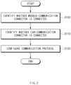
- FIG. 2 is a view showing an operating method of a battery management apparatus according to an embodiment disclosed herein.
- the operating method of the battery management apparatus may include operation S 100 of identifying whether a Modbus-communication connector is connected, operation S 110 of identifying whether a CAN-communication connector is connected, and operation S 120 of configuring a communication protocol.
- the operating method of the battery management structure may refer to FIG. 1 .
- FIG. 1 The operating method of the battery management structure.
- the battery management apparatus 100 may identify whether the Modbus-communication connector is connected.
- the battery management apparatus 100 may identify whether the Modbus-communication connector is connected, based on whether normal power supplied to the Ethernet port is detected.
- the battery management apparatus 100 may use one of a plurality of pins connected to the Ethernet port as a terminal for identifying whether the Modbus-communication connector is connected.
- operation S100 in which the battery management apparatus 100 determines whether the Modbus-communication connector is connected may be referred to as a first identifying operation.
- operation S 100 may be performed by the first identifying unit 110 of the battery management apparatus 100.
- the battery management apparatus 100 may identify whether the CAN-communication connector is connected.
- the battery management apparatus 100 may identify whether the Modbus-communication connector is connected, based on whether normal power supplied to the CAN port is detected.
- the battery management apparatus 100 may use one of a plurality of pins connected to the CAN port as a terminal for identifying whether the CAN-communication connector is connected.
- operation S110 in which the battery management apparatus 100 determines whether the CAN-communication connector is connected may be referred to as a second identifying operation.
- operation 5110 may be performed by the second identifying unit 120 of the battery management apparatus 100.
- operations S100 and S110 may be performed at the same time or in any order.
- the battery management apparatus 100 may configure a communication protocol.
- the battery management apparatus 100 may configure the communication protocol based on an identification result of operation S100 and/or operation S110.
- the battery management apparatus 100 may configure the CAN-communication protocol when identifying that the CAN-communication connector is connected in operation S110.
- the battery management apparatus 100 may configure the Modbus-communication protocol when identifying that the Modbus-communication connector is connected in operation S100.
- Operation S120 may be performed by the controller 130 of the battery management apparatus 100.
- the battery management apparatus 100 may select and configure the CAN-communication protocol or the Modbus-communication protocol when identifying that both the CAN-communication connector and the Modbus-communication connector are connected.
- the battery management apparatus 100 may configure the CAN-communication protocol preferentially over the Modbus-communication protocol when identifying that both the CAN-communication connector and the Modbus-communication connector are connected.
- operation S120 may include an operation in which the battery management apparatus 100 is allocated with the ID.
- the operation in which the battery management apparatus 100 is allocated with the ID will be described in detail with reference to FIG. 3 .
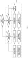
- FIG. 3 is a view showing in detail an operating method of a battery management apparatus, according to an embodiment disclosed herein.
- the operating method of the battery management apparatus may include operation S200 of identifying whether Modbus-communication is possible, operation S210 of identifying whether CAN communication is possible, and operation S220 of allocating the ID of the battery management apparatus 100 and configuring a communication protocol of the battery management apparatus 100.
- the battery management apparatus 100 may identify whether Modbus communication is possible. Operation S200 may be substantially the same as operation S100 of FIG. 2 . Operation S200 may be performed by the first identifying unit 110 of the battery management apparatus 100.
- the battery management apparatus 100 may identify whether CAN communication is possible. Operation S210 may be substantially the same as operation S110 of FIG. 2 . Operation S210 may be performed by the second identifying unit 120 of the battery management apparatus 100.
- Operations S211 and S212 may be detailed embodiments of operation S210.
- the battery management apparatus 100 may identify whether CAN communication of the battery management apparatus 100 is possible in operation S211, or identify whether CAN communication of the battery management apparatus 100 is possible in operation S212 when Modbus communication is not possible.
- operations S200 and S210 may be performed at the same time or in any order.
- the battery management apparatus 100 may perform operation S210 before operation S200.
- operation S200 may be embodied into an operation of identifying whether Modbus communication of the battery management apparatus 100 is possible when CAN communication is possible and an operation of identifying whether Modbus communication of the battery management apparatus 100 is possible when CAN communication is not possible.
- the battery management apparatus 100 may allocate an ID or configure a communication protocol. Operation S220 may be substantially the same as operation S120 of FIG. 2 . The battery management apparatus 100 may perform operation S220 based on identification results of operation S00 and operation S210.
- the battery management apparatus 100 may include operation S221, S223, or S225 of allocating an ID of the battery management apparatus 100 through CAN communication or Modbus-TCP.
- the battery management apparatus 100 may allocate the ID of the battery management apparatus 100 through CAN communication when identifying that Modbus communication and CAN communication are possible in operations S200 and S211.
- the battery management apparatus 100 allocated with the ID in operation S221 may configure a CAN-communication protocol and/or a Modbus-communication protocol.
- the battery management apparatus 100 may configure the CAN communication protocol preferentially over the Modbus-communication protocol or select the CAN-communication and the Modbus-communication protocol at random and configure the selected one.
- the battery management apparatus 100 may communicate with another electronic device through a communication protocol configured in operation S222.
- the other electronic device may include an external battery management apparatus.
- the battery management apparatus 100 may allocate the ID through Modbus-TCP when identifying that Modbus communication is possible, but CAN communication is not possible in operations S200 and S211.
- the battery management apparatus 100 allocated with the ID in operation S223 may configure the Modbus-communication protocol.
- the battery management apparatus 100 may communicate with the other electronic device (e.g., the external battery management apparatus, etc.) through the Modbus-communication protocol.
- the battery management apparatus 100 may allocate the ID through CAN communication when identifying that CAN communication is possible, but Modbus communication is not possible in operations S200 and S212.
- the battery management apparatus 100 allocated with the ID in operation S225 may configure the CAN-communication protocol.
- the battery management apparatus 100 may communicate with the other electronic device (e.g., the external battery management apparatus, etc.) through the CAN-communication protocol.
- the battery management apparatus 100 may maintain a communication standby state when identifying that either Modbus communication or CAN communication is not possible in operations S200 and S212.
- the battery management apparatus 100 in the communication standby state may identify whether Modbus communication is possible and/or whether CAN communication is possible, in real time or in every preset periods, and repeatedly perform operation S200, operation S210, and/or operation S220.
- the battery management apparatus 100 when the battery management apparatus 100 allocates an ID through CAN communication in operations S221 and S225, the battery management apparatus 100 may use a well-known ID allocation method known as a method of allocating the ID of the battery management apparatus 100 connected in a daisy chain through a wake-up signal, and the method is not specially limited.
- the battery management apparatus 100 may allocate the ID according to a pre-stored command logic, and as long as the ID allocation method is one under Modbus communication, a type thereof is not specially limited.
- FIG. 4 is a diagram simply showing a battery management apparatus including a memory module, according to an embodiment disclosed herein.
- a computing system 10 may include an MCU 12, a memory 14, an input/output I/F 16, and a communication I/F 18.
- the MCU 12 may be a processor that executes various programs (e.g., a feature calculation program, a class classification and lifespan estimation program, etc.) stored in the memory 14, processes various data including voltage, current, etc., of a battery cell through these programs, and executes the above-described functions of the battery management apparatus shown in FIGS. 1 to 3 .
- programs e.g., a feature calculation program, a class classification and lifespan estimation program, etc.
- the memory 14 may store various programs regarding feature calculation, class classification, and lifespan estimation of the battery cell. Moreover, the memory 14 may store various data such as a voltage, a current, feature data, etc., of each battery cell.
- the memory 14 may be provided in plural, depending on a need.
- the memory 14 may be volatile memory or non-volatile memory.
- RAM random access memory
- DRAM dynamic RAM
- SRAM static RAM
- ROM read only memory
- PROM programmable ROM
- EAROM electrically alterable ROM
- EPROM erasable PROM
- EEPROM electrically erasable PROM
- flash memory etc.
- the above-listed examples of the memory 14 are merely examples and are not limited thereto.
- the input/output I/F 16 may provide an interface for transmitting and receiving data by connecting an input device (not shown) such as a keyboard, a mouse, a touch panel, etc., and an output device such as a display (not shown), etc., to the MCU 12.
- an input device such as a keyboard, a mouse, a touch panel, etc.
- an output device such as a display (not shown), etc.
- the communication I/F 18, which is a component capable of transmitting and receiving various data to and from a server, may be various devices capable of supporting wired or wireless communication.
- a program for feature calculation, class classification, and lifespan estimation for a battery cell or various data, etc. may be transmitted and received to and from a separately provided external server through the communication I/F 18.
- a computer program according to an embodiment disclosed herein may be recorded in the memory 14 and processed by the MCU 12, thus being implemented as a module that performs functions shown in FIG. 2 or 3 .
Landscapes
- Engineering & Computer Science (AREA)
- Computer Networks & Wireless Communication (AREA)
- Signal Processing (AREA)
- Physics & Mathematics (AREA)
- General Physics & Mathematics (AREA)
- Theoretical Computer Science (AREA)
- General Engineering & Computer Science (AREA)
- Computer Hardware Design (AREA)
- Environmental & Geological Engineering (AREA)
- Charge And Discharge Circuits For Batteries Or The Like (AREA)
Applications Claiming Priority (2)
| Application Number | Priority Date | Filing Date | Title |
|---|---|---|---|
| KR1020220011604A KR20230115074A (ko) | 2022-01-26 | 2022-01-26 | 배터리 관리 장치 및 그의 동작 방법 |
| PCT/KR2023/000325 WO2023146156A1 (ko) | 2022-01-26 | 2023-01-06 | 배터리 관리 장치 및 그의 동작 방법 |
Publications (2)
| Publication Number | Publication Date |
|---|---|
| EP4456487A1 true EP4456487A1 (de) | 2024-10-30 |
| EP4456487A4 EP4456487A4 (de) | 2025-04-09 |
Family
ID=87471811
Family Applications (1)
| Application Number | Title | Priority Date | Filing Date |
|---|---|---|---|
| EP23747199.0A Pending EP4456487A4 (de) | 2022-01-26 | 2023-01-06 | Batterieverwaltungsvorrichtung und betriebsverfahren dafür |
Country Status (6)
| Country | Link |
|---|---|
| US (1) | US20250103541A1 (de) |
| EP (1) | EP4456487A4 (de) |
| JP (1) | JP7794532B2 (de) |
| KR (1) | KR20230115074A (de) |
| CN (1) | CN118525487A (de) |
| WO (1) | WO2023146156A1 (de) |
Family Cites Families (23)
| Publication number | Priority date | Publication date | Assignee | Title |
|---|---|---|---|---|
| JP2001086187A (ja) * | 1999-09-14 | 2001-03-30 | Sharp Corp | 双方向通信システム |
| US7721079B2 (en) * | 2000-04-10 | 2010-05-18 | Rockwell Automation Technologies, Inc. | Pointbus architecture and automatic sequential addressing |
| KR20030095828A (ko) * | 2002-06-14 | 2003-12-24 | 삼성전자주식회사 | 주변기기 인터페이스 장치 및 그에 적합한 우선 순위 제어방법 |
| US10270719B2 (en) * | 2013-09-10 | 2019-04-23 | Illinois Tool Works Inc. | Methods for handling data packets in a digital network of a welding system |
| CN103678779A (zh) * | 2013-11-25 | 2014-03-26 | 南方电网科学研究院有限责任公司 | 一种储能系统iec61850数据建模方法 |
| US10095650B2 (en) * | 2016-04-04 | 2018-10-09 | A-Dec, Inc. | High speed controller area network (CAN) in dental equipment |
| US10333887B2 (en) * | 2016-08-15 | 2019-06-25 | Cisco Technology, Inc. | Internet protocol (IP) network virtualization of serial network endpoints |
| KR101969763B1 (ko) * | 2016-11-03 | 2019-04-17 | 에스케이이노베이션 주식회사 | 배터리 관리 시스템 및 통신 id 할당 방법 |
| US10320034B2 (en) * | 2017-03-03 | 2019-06-11 | The Boeing Company | Modular battery with battery cell and submodule interconnectivity |
| US10412200B2 (en) * | 2017-10-13 | 2019-09-10 | Abb Schweiz Ag | Reconfigurable extended communication interface devices for monitoring and control of power system devices |
| US11417927B2 (en) * | 2018-11-13 | 2022-08-16 | Rivian Ip Holdings, Llc | Auxiliary energy system architecture |
| US11394231B2 (en) * | 2019-02-01 | 2022-07-19 | Moser Energy Systems | Hybrid generator system and method of operation and control |
| JP6731602B1 (ja) * | 2019-02-28 | 2020-07-29 | 株式会社安川電機 | スレーブ機器及び通信システム |
| KR102753091B1 (ko) * | 2020-02-26 | 2025-01-09 | 주식회사 엘지에너지솔루션 | 배터리 정보 제공 장치 및 방법 |
| CN116529978B (zh) * | 2020-06-02 | 2026-04-03 | 茵范帝能源公司 | 大型电池管理系统 |
| US11489343B2 (en) * | 2020-06-02 | 2022-11-01 | Inventus Power, Inc. | Hardware short circuit protection in a large battery pack |
| US11588334B2 (en) * | 2020-06-02 | 2023-02-21 | Inventus Power, Inc. | Broadcast of discharge current based on state-of-health imbalance between battery packs |
| US11594892B2 (en) * | 2020-06-02 | 2023-02-28 | Inventus Power, Inc. | Battery pack with series or parallel identification signal |
| US11538347B2 (en) * | 2020-06-12 | 2022-12-27 | Workhorse Group Inc. | UAV delivery control system for UAV delivery of packages |
| CN214014250U (zh) * | 2020-12-14 | 2021-08-20 | 常州中海电力科技有限公司 | 一种新型电池包检测设备的数据通信模块 |
| CN112866018A (zh) * | 2021-01-10 | 2021-05-28 | 宜昌科赛新能源科技有限公司 | 物联网管理系统及方法 |
| CN112821374A (zh) * | 2021-01-28 | 2021-05-18 | 上海明华电力科技有限公司 | 一种支持即插即用的智能直流微电网系统 |
| KR102429084B1 (ko) | 2021-09-10 | 2022-08-04 | 상지테크 주식회사 | 이열 말뚝 자립형 흙막이 공법 |
-
2022
- 2022-01-26 KR KR1020220011604A patent/KR20230115074A/ko active Pending
-
2023
- 2023-01-06 EP EP23747199.0A patent/EP4456487A4/de active Pending
- 2023-01-06 JP JP2024541705A patent/JP7794532B2/ja active Active
- 2023-01-06 CN CN202380016853.1A patent/CN118525487A/zh active Pending
- 2023-01-06 WO PCT/KR2023/000325 patent/WO2023146156A1/ko not_active Ceased
- 2023-01-06 US US18/832,263 patent/US20250103541A1/en active Pending
Also Published As
| Publication number | Publication date |
|---|---|
| JP2025502177A (ja) | 2025-01-24 |
| US20250103541A1 (en) | 2025-03-27 |
| EP4456487A4 (de) | 2025-04-09 |
| KR20230115074A (ko) | 2023-08-02 |
| JP7794532B2 (ja) | 2026-01-06 |
| CN118525487A (zh) | 2024-08-20 |
| WO2023146156A1 (ko) | 2023-08-03 |
Similar Documents
| Publication | Publication Date | Title |
|---|---|---|
| KR102834457B1 (ko) | 배터리 상태 진단 장치 및 방법 | |
| EP3958371A1 (de) | Batterieverwaltungsvorrichtung und verfahren sowie batteriesystem damit | |
| AU2023376088A1 (en) | Battery diagnosis apparatus and operating method thereof | |
| EP4280052A1 (de) | Firmware-aktualisierungssystem eines batterieverwaltungssystems und zugehöriges verfahren | |
| EP4202465A1 (de) | Batterieverwaltungsvorrichtung und -verfahren | |
| US20250103541A1 (en) | Battery management apparatus and operating method thereof | |
| EP4692824A1 (de) | Batterieverwaltungsvorrichtung und betriebsverfahren dafür | |
| EP4628912A1 (de) | Batteriediagnosevorrichtung und betriebsverfahren dafür | |
| EP4503379A1 (de) | Batteriewechselsystem und betriebsverfahren dafür | |
| EP4653897A1 (de) | Batteriediagnosevorrichtung und betriebsverfahren dafür | |
| EP4365613B1 (de) | Batteriepack und betriebsverfahren dafür | |
| EP4564032A1 (de) | Batterieverwaltungsvorrichtung und betriebsverfahren dafür | |
| EP4325232A1 (de) | Batterieverwaltungsvorrichtung und betriebsverfahren dafür | |
| US20240421610A1 (en) | Battery Control System and Method for Managing Battery State | |
| JP2025527639A (ja) | 電池の異常を検知する電子装置およびその動作方法 | |
| EP4207540A1 (de) | Messvorrichtung und -verfahren | |
| US12025672B2 (en) | Battery management apparatus and method | |
| CN119768698A (zh) | 电池管理装置及其操作方法 | |
| EP4607218A1 (de) | Batterieentladungsdiagnosevorrichtung und betriebsverfahren dafür | |
| EP4632410A1 (de) | Batterieanomaliediagnosevorrichtung und verfahren zum betrieb davon | |
| EP4682564A1 (de) | Batterieverwaltungsvorrichtung und batterieverwaltungsverfahren | |
| US20250271503A1 (en) | Battery Abnormality Diagnosis Apparatus and Operating Method Thereof | |
| EP4697046A1 (de) | Batteriediagnosevorrichtung und betriebsverfahren dafür | |
| KR20250069094A (ko) | 배터리 교환 스테이션 및 그것의 동작 방법 | |
| KR20260029127A (ko) | 배터리 진단 장치 및 그 방법 |
Legal Events
| Date | Code | Title | Description |
|---|---|---|---|
| STAA | Information on the status of an ep patent application or granted ep patent |
Free format text: STATUS: THE INTERNATIONAL PUBLICATION HAS BEEN MADE |
|
| PUAI | Public reference made under article 153(3) epc to a published international application that has entered the european phase |
Free format text: ORIGINAL CODE: 0009012 |
|
| STAA | Information on the status of an ep patent application or granted ep patent |
Free format text: STATUS: REQUEST FOR EXAMINATION WAS MADE |
|
| 17P | Request for examination filed |
Effective date: 20240726 |
|
| AK | Designated contracting states |
Kind code of ref document: A1 Designated state(s): AL AT BE BG CH CY CZ DE DK EE ES FI FR GB GR HR HU IE IS IT LI LT LU LV MC ME MK MT NL NO PL PT RO RS SE SI SK SM TR |
|
| A4 | Supplementary search report drawn up and despatched |
Effective date: 20250311 |
|
| RIC1 | Information provided on ipc code assigned before grant |
Ipc: H04L 43/0811 20220101ALN20250305BHEP Ipc: G01R 31/371 20190101ALN20250305BHEP Ipc: H04L 61/5038 20220101ALI20250305BHEP Ipc: H04L 12/40 20060101AFI20250305BHEP |
|
| DAV | Request for validation of the european patent (deleted) | ||
| DAX | Request for extension of the european patent (deleted) | ||
| STAA | Information on the status of an ep patent application or granted ep patent |
Free format text: STATUS: EXAMINATION IS IN PROGRESS |
|
| 17Q | First examination report despatched |
Effective date: 20260112 |