EP4456174A2 - Festkörpersekundärbatterie - Google Patents
Festkörpersekundärbatterie Download PDFInfo
- Publication number
- EP4456174A2 EP4456174A2 EP24165740.2A EP24165740A EP4456174A2 EP 4456174 A2 EP4456174 A2 EP 4456174A2 EP 24165740 A EP24165740 A EP 24165740A EP 4456174 A2 EP4456174 A2 EP 4456174A2
- Authority
- EP
- European Patent Office
- Prior art keywords
- layer
- active material
- negative
- carbonaceous
- solid electrolyte
- Prior art date
- Legal status (The legal status is an assumption and is not a legal conclusion. Google has not performed a legal analysis and makes no representation as to the accuracy of the status listed.)
- Pending
Links
Images


Classifications
-
- H—ELECTRICITY
- H01—ELECTRIC ELEMENTS
- H01M—PROCESSES OR MEANS, e.g. BATTERIES, FOR THE DIRECT CONVERSION OF CHEMICAL ENERGY INTO ELECTRICAL ENERGY
- H01M10/00—Secondary cells; Manufacture thereof
- H01M10/05—Accumulators with non-aqueous electrolyte
- H01M10/052—Li-accumulators
-
- H—ELECTRICITY
- H01—ELECTRIC ELEMENTS
- H01M—PROCESSES OR MEANS, e.g. BATTERIES, FOR THE DIRECT CONVERSION OF CHEMICAL ENERGY INTO ELECTRICAL ENERGY
- H01M10/00—Secondary cells; Manufacture thereof
- H01M10/05—Accumulators with non-aqueous electrolyte
- H01M10/052—Li-accumulators
- H01M10/0525—Rocking-chair batteries, i.e. batteries with lithium insertion or intercalation in both electrodes; Lithium-ion batteries
-
- H—ELECTRICITY
- H01—ELECTRIC ELEMENTS
- H01M—PROCESSES OR MEANS, e.g. BATTERIES, FOR THE DIRECT CONVERSION OF CHEMICAL ENERGY INTO ELECTRICAL ENERGY
- H01M10/00—Secondary cells; Manufacture thereof
- H01M10/05—Accumulators with non-aqueous electrolyte
- H01M10/056—Accumulators with non-aqueous electrolyte characterised by the materials used as electrolytes, e.g. mixed inorganic/organic electrolytes
- H01M10/0561—Accumulators with non-aqueous electrolyte characterised by the materials used as electrolytes, e.g. mixed inorganic/organic electrolytes the electrolyte being constituted of inorganic materials only
- H01M10/0562—Solid materials
-
- H—ELECTRICITY
- H01—ELECTRIC ELEMENTS
- H01M—PROCESSES OR MEANS, e.g. BATTERIES, FOR THE DIRECT CONVERSION OF CHEMICAL ENERGY INTO ELECTRICAL ENERGY
- H01M10/00—Secondary cells; Manufacture thereof
- H01M10/42—Methods or arrangements for servicing or maintenance of secondary cells or secondary half-cells
- H01M10/4235—Safety or regulating additives or arrangements in electrodes, separators or electrolyte
-
- H—ELECTRICITY
- H01—ELECTRIC ELEMENTS
- H01M—PROCESSES OR MEANS, e.g. BATTERIES, FOR THE DIRECT CONVERSION OF CHEMICAL ENERGY INTO ELECTRICAL ENERGY
- H01M4/00—Electrodes
- H01M4/02—Electrodes composed of, or comprising, active material
- H01M4/13—Electrodes for accumulators with non-aqueous electrolyte, e.g. for lithium-accumulators; Processes of manufacture thereof
- H01M4/133—Electrodes based on carbonaceous material, e.g. graphite-intercalation compounds or CFx
-
- H—ELECTRICITY
- H01—ELECTRIC ELEMENTS
- H01M—PROCESSES OR MEANS, e.g. BATTERIES, FOR THE DIRECT CONVERSION OF CHEMICAL ENERGY INTO ELECTRICAL ENERGY
- H01M4/00—Electrodes
- H01M4/02—Electrodes composed of, or comprising, active material
- H01M4/13—Electrodes for accumulators with non-aqueous electrolyte, e.g. for lithium-accumulators; Processes of manufacture thereof
- H01M4/134—Electrodes based on metals, Si or alloys
-
- H—ELECTRICITY
- H01—ELECTRIC ELEMENTS
- H01M—PROCESSES OR MEANS, e.g. BATTERIES, FOR THE DIRECT CONVERSION OF CHEMICAL ENERGY INTO ELECTRICAL ENERGY
- H01M4/00—Electrodes
- H01M4/02—Electrodes composed of, or comprising, active material
- H01M4/36—Selection of substances as active materials, active masses, active liquids
- H01M4/362—Composites
- H01M4/366—Composites as layered products
-
- H—ELECTRICITY
- H01—ELECTRIC ELEMENTS
- H01M—PROCESSES OR MEANS, e.g. BATTERIES, FOR THE DIRECT CONVERSION OF CHEMICAL ENERGY INTO ELECTRICAL ENERGY
- H01M4/00—Electrodes
- H01M4/02—Electrodes composed of, or comprising, active material
- H01M4/36—Selection of substances as active materials, active masses, active liquids
- H01M4/38—Selection of substances as active materials, active masses, active liquids of elements or alloys
- H01M4/381—Alkaline or alkaline earth metals elements
- H01M4/382—Lithium
-
- H—ELECTRICITY
- H01—ELECTRIC ELEMENTS
- H01M—PROCESSES OR MEANS, e.g. BATTERIES, FOR THE DIRECT CONVERSION OF CHEMICAL ENERGY INTO ELECTRICAL ENERGY
- H01M4/00—Electrodes
- H01M4/02—Electrodes composed of, or comprising, active material
- H01M4/36—Selection of substances as active materials, active masses, active liquids
- H01M4/38—Selection of substances as active materials, active masses, active liquids of elements or alloys
- H01M4/40—Alloys based on alkali metals
- H01M4/405—Alloys based on lithium
-
- H—ELECTRICITY
- H01—ELECTRIC ELEMENTS
- H01M—PROCESSES OR MEANS, e.g. BATTERIES, FOR THE DIRECT CONVERSION OF CHEMICAL ENERGY INTO ELECTRICAL ENERGY
- H01M4/00—Electrodes
- H01M4/02—Electrodes composed of, or comprising, active material
- H01M4/36—Selection of substances as active materials, active masses, active liquids
- H01M4/58—Selection of substances as active materials, active masses, active liquids of inorganic compounds other than oxides or hydroxides, e.g. sulfides, selenides, tellurides, halogenides or LiCoFy; of polyanionic structures, e.g. phosphates, silicates or borates
- H01M4/583—Carbonaceous material, e.g. graphite-intercalation compounds or CFx
- H01M4/587—Carbonaceous material, e.g. graphite-intercalation compounds or CFx for inserting or intercalating light metals
-
- H—ELECTRICITY
- H01—ELECTRIC ELEMENTS
- H01M—PROCESSES OR MEANS, e.g. BATTERIES, FOR THE DIRECT CONVERSION OF CHEMICAL ENERGY INTO ELECTRICAL ENERGY
- H01M4/00—Electrodes
- H01M4/02—Electrodes composed of, or comprising, active material
- H01M4/62—Selection of inactive substances as ingredients for active masses, e.g. binders, fillers
- H01M4/624—Electric conductive fillers
- H01M4/625—Carbon or graphite
-
- H—ELECTRICITY
- H01—ELECTRIC ELEMENTS
- H01M—PROCESSES OR MEANS, e.g. BATTERIES, FOR THE DIRECT CONVERSION OF CHEMICAL ENERGY INTO ELECTRICAL ENERGY
- H01M4/00—Electrodes
- H01M4/02—Electrodes composed of, or comprising, active material
- H01M4/64—Carriers or collectors
- H01M4/66—Selection of materials
- H01M4/661—Metal or alloys, e.g. alloy coatings
-
- H—ELECTRICITY
- H01—ELECTRIC ELEMENTS
- H01M—PROCESSES OR MEANS, e.g. BATTERIES, FOR THE DIRECT CONVERSION OF CHEMICAL ENERGY INTO ELECTRICAL ENERGY
- H01M4/00—Electrodes
- H01M4/02—Electrodes composed of, or comprising, active material
- H01M4/64—Carriers or collectors
- H01M4/66—Selection of materials
- H01M4/665—Composites
- H01M4/667—Composites in the form of layers, e.g. coatings
-
- H—ELECTRICITY
- H01—ELECTRIC ELEMENTS
- H01M—PROCESSES OR MEANS, e.g. BATTERIES, FOR THE DIRECT CONVERSION OF CHEMICAL ENERGY INTO ELECTRICAL ENERGY
- H01M4/00—Electrodes
- H01M4/02—Electrodes composed of, or comprising, active material
- H01M4/64—Carriers or collectors
- H01M4/66—Selection of materials
- H01M4/668—Composites of electroconductive material and synthetic resins
-
- H—ELECTRICITY
- H01—ELECTRIC ELEMENTS
- H01M—PROCESSES OR MEANS, e.g. BATTERIES, FOR THE DIRECT CONVERSION OF CHEMICAL ENERGY INTO ELECTRICAL ENERGY
- H01M4/00—Electrodes
- H01M4/02—Electrodes composed of, or comprising, active material
- H01M2004/021—Physical characteristics, e.g. porosity, surface area
-
- H—ELECTRICITY
- H01—ELECTRIC ELEMENTS
- H01M—PROCESSES OR MEANS, e.g. BATTERIES, FOR THE DIRECT CONVERSION OF CHEMICAL ENERGY INTO ELECTRICAL ENERGY
- H01M4/00—Electrodes
- H01M4/02—Electrodes composed of, or comprising, active material
- H01M2004/026—Electrodes composed of, or comprising, active material characterised by the polarity
- H01M2004/027—Negative electrodes
-
- H—ELECTRICITY
- H01—ELECTRIC ELEMENTS
- H01M—PROCESSES OR MEANS, e.g. BATTERIES, FOR THE DIRECT CONVERSION OF CHEMICAL ENERGY INTO ELECTRICAL ENERGY
- H01M2300/00—Electrolytes
- H01M2300/0017—Non-aqueous electrolytes
- H01M2300/0065—Solid electrolytes
- H01M2300/0068—Solid electrolytes inorganic
- H01M2300/008—Halides
-
- H—ELECTRICITY
- H01—ELECTRIC ELEMENTS
- H01M—PROCESSES OR MEANS, e.g. BATTERIES, FOR THE DIRECT CONVERSION OF CHEMICAL ENERGY INTO ELECTRICAL ENERGY
- H01M2300/00—Electrolytes
- H01M2300/0088—Composites
- H01M2300/0094—Composites in the form of layered products, e.g. coatings
-
- Y—GENERAL TAGGING OF NEW TECHNOLOGICAL DEVELOPMENTS; GENERAL TAGGING OF CROSS-SECTIONAL TECHNOLOGIES SPANNING OVER SEVERAL SECTIONS OF THE IPC; TECHNICAL SUBJECTS COVERED BY FORMER USPC CROSS-REFERENCE ART COLLECTIONS [XRACs] AND DIGESTS
- Y02—TECHNOLOGIES OR APPLICATIONS FOR MITIGATION OR ADAPTATION AGAINST CLIMATE CHANGE
- Y02E—REDUCTION OF GREENHOUSE GAS [GHG] EMISSIONS, RELATED TO ENERGY GENERATION, TRANSMISSION OR DISTRIBUTION
- Y02E60/00—Enabling technologies; Technologies with a potential or indirect contribution to GHG emissions mitigation
- Y02E60/10—Energy storage using batteries
Definitions
- Embodiments of the present disclosed described herein are related to an all-solid secondary battery.
- Lithium batteries are utilized in information devices, communication devices, vehicles, and/or the like.
- Safety is important in vehicles, because vehicles are related to people's wellbeing.
- a liquid electrolyte-containing lithium battery includes a flammable organic solvent. Liquid electrolyte-containing lithium batteries have high risks of overheating and fire if (e.g., when) a short circuit occurs.
- solid electrolyte-containing lithium batteries may provide improved safety compared to liquid electrolyte-containing lithium batteries.
- Sulfide-based solid electrolytes easily react with a negative current collector to cause side reactions. For example, side reactions occurring between a sulfide-based solid electrolyte and a copper current collect if (e.g., when) the sulfide-based solid electrolyte is brought into contact with the copper current collector during a charging and discharging process may deteriorate lifespan of lithium batteries. Therefore, it is desired or suitable to develop methods of blocking contact between a sulfide-based solid electrolyte and a negative current collector.
- a negative active material layer is disposed between a solid electrolyte layer and a negative current collector by a wet method, it is difficult to form a substantially uniform thickness of the negative active material layer.
- a thickness difference of the negative active material layer may cause substantially non-uniform plating of lithium and growth of lithium dendrite between the negative active material layer and the negative current collector.
- a short circuit may occur in a lithium battery due to such substantially non-uniform plating of lithium and/or growth of lithium dendrite. It is thus desired or suitable to develop methods of reducing the thickness difference of the negative active material layer.
- a negative active material layer may easily aggregate in the negative active material layer during a drying process.
- Substantially non-uniform current density may be formed in the negative active material layer due to the aggregated negative active material.
- the substantially non-uniform current density may cause substantially non-uniform plating of lithium and/or growth of lithium dendrite between the negative active material layer and the negative current collector.
- a short circuit may occur in a lithium battery due to the substantially non-uniform plating of lithium and/or growth of lithium dendrite. It is thus desired or suitable to develop methods of inhibiting aggregation of the negative active material in the negative active material layer.
- aspects according to one or more embodiments are directed to an all-solid secondary battery having a new structure is provided.
- an all-solid secondary battery includes:
- “at least one of a, b or c”, “at least one selected from a, b and c”, etc. may indicate only a, only b, only c, both (e.g., simultaneously) a and b, both (e.g., simultaneously) a and c, both (e.g., simultaneously) b and c, all of a, b, and c, or variations thereof.
- first”, “second”, “third”, and/or the like may be utilized herein to describe one or more suitable elements, components, regions, layers, and/or sections, these elements, components, regions, layers and/or sections should not be limited by these terms. These terms are only utilized to distinguish one element, component, region, layer or section from another region, layer or section. Thus, a first element, component, region, layer, or section discussed herein could be termed a second element, component, region, layer or section without departing from the teachings herein.
- spatially relative terms such as “under”, “below”, “lower”, “on”, “above”, or “upper”, may be utilized herein for ease of description of the relationship of one element or feature to another element(s) or feature(s) as illustrated in the drawings. It will be understood that the spatially relative terms are intended to encompass different orientations of a device in utilize or operation, in addition to the orientation depicted in the drawings. For example, when the device in the drawings is turned over, elements described as “below” other elements or features would then be oriented “above” the other elements or features. Thus, the example term “below” may encompass both (e.g., simultaneously) an orientation of above and below. The device may be otherwise oriented (rotated 90 degrees or at other orientations) and the spatially relative descriptors utilized herein interpreted accordingly.
- Example embodiments will be described herein with reference to schematic cross-sectional view of ideal embodiments. As such, variations from the shapes of the illustrations as a result, for example, of manufacturing techniques and/or tolerances, are to be expected. Thus, example embodiments should not be construed as limited to the particular shapes of regions illustrated herein but are to include deviations in shapes that result, for example, from manufacturing. For example, a region illustrated or described as flat may, typically, have rough and/or nonlinear features. Moreover, sharp angles illustrated in the drawings may be rounded. Thus, the regions illustrated in the drawings are schematic in nature and their shapes are not intended to illustrate the actual shape of a region of a device and are not intended to limit the scope of claims.
- Group refers to a group of elements in the periodic table numbered from 1 to 18 classified according to a classification system of The International Union of Pure and Applied Chemistry (“IUPAC").
- a "particle diameter" of particles may indicate an average diameter of spherical particles or an average length of major axes of non-spherical particles. Particle diameters may be measured utilizing a particle size analyzer (PSA).
- PSD particle size analyzer
- the "particle diameter” may be, for example, an average particle diameter.
- the “average particle diameter” may be, for example, a median particle diameter (D50).
- D50 may refer to a particle diameter corresponding to 50 % of the particles in a cumulative distribution curve measured by a laser diffraction method in which particles are accumulated in the order of particle diameter from the smallest particle to the largest particle.
- D90 may refer to a particle diameter corresponding to 90 % of the particles in a cumulative distribution curve measured by a laser diffraction method in which particles are accumulated in the order of particle diameter from the smallest particle to the largest particle.
- D10 may refer to a particle diameter corresponding to 10 % of the particles in a cumulative distribution curve measured by a laser diffraction method in which particles are accumulated in the order of particle diameter from the smallest particle to the largest particle.
- the "particle diameter" may be determined, for example, based on manuals or utilizing software from cross-sectional images of a scanning electron microscope and/or a transmission electron microscope, and may be an arithmetic average of particle diameters of a plurality of particles.
- metal may include metals and metalloids such as silicon and germanium in an elemental or ionic state.
- alloy may refer to a mixture of two or more metals.
- electrode active material may refer to a material for electrodes allowing lithiation and delithiation.
- positive active material may refer to a material for positive electrodes allowing lithiation and delithiation.
- negative active material may refer to a material for negative electrodes allowing lithiation and delithiation.
- lithiumation and “lithiating” may refer to a process of adding lithium to an electrode active material.
- the terms “delithiation” and “delithiating” may refer to a process of removing lithium from an electrode active material.
- the terms “charging” and “charge” may refer to a process of supplying electrochemical energy to a battery.
- the terms “discharging” and “discharge” may refer to a process of removing electrochemical energy from a battery.
- positive electrode and “cathode” may refer to an electrode in which electrochemical reduction and lithiation occur during discharging.
- negative electrode and “anode” may refer to an electrode in which electrochemical oxidation and delithiation occur during discharging.
- the term “substantially” and similar terms are utilized as terms of approximation and not as terms of degree, and are intended to account for the inherent deviations in measured or calculated values that would be recognized by those of ordinary skill in the art.
- the term “about” and similar terms when utilized herein in connection with a numerical value or a numerical range, are inclusive of the stated value and a value within an acceptable range of deviation for the particular value as determined by one of ordinary skill in the art, considering the measurement in question and the error associated with measurement of the particular quantity (e.g., the limitations of the measurement system). For example, “about” may refer to within one or more standard deviations, or within ⁇ 30%, 20%, 10%, 5% of the stated value.
- any numerical range recited herein is intended to include all subranges of the same numerical precision subsumed within the recited range.
- a range of "1.0 to 10.0" is intended to include all subranges between (and including) the recited minimum value of 1.0 and the recited maximum value of 10.0, that is, having a minimum value equal to or greater than 1.0 and a maximum value equal to or less than 10.0, such as, for example, 2.4 to 7.6.
- Any maximum numerical limitation recited herein is intended to include all lower numerical limitations subsumed therein and any minimum numerical limitation recited in this specification is intended to include all higher numerical limitations subsumed therein. Accordingly, Applicant reserves the right to amend this specification, including the claims, to expressly recite any sub-range subsumed within the ranges expressly recited herein.
- fibrous shape refers to the fibrous shape of a substance that has a larger aspect ratio than a particulate of said substance.
- fibrous shape refers to a process of converting (e.g., by grinding or pulverizing) particulates of a substance into fibrous shape (i.e., fibrils) of said substance that has higher aspect ratio than the particulates.
- An all-solid secondary battery may include: a positive electrode layer; a negative electrode layer; and a solid electrolyte layer disposed between the positive electrode layer and the negative electrode layer, wherein the positive electrode layer includes a positive current collector and a positive active material layer, the solid electrolyte layer includes a sulfide-based solid electrolyte, and the negative electrode layer includes a negative current collector, a first negative active material layer, and a first protective layer disposed between the negative current collector and the first negative active material layer, wherein the first negative active material layer includes a carbonaceous material matrix and a metallic negative active material located in the carbonaceous material matrix, and the carbonaceous material matrix includes a first carbonaceous nanostructure, and the first protective layer includes a second carbonaceous nanostructure.
- the first negative active material layer includes the carbonaceous nanostructure arranged by a dry method
- defects such as thickness non-uniformity of a negative active material layer and aggregation of a negative active material occurring in a wet negative active material layer may be prevented or reduced.
- Substantially non-uniform plating of lithium and/or growth of lithium dendrite may be inhibited during a charging and discharging process because the all-solid secondary battery includes the first negative active material layer.
- a short circuit of the all-solid secondary battery may be prevented or reduced and lifespan characteristics thereof may be improved.
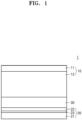
- an all-solid secondary battery 1 may include a positive electrode layer 10; a negative electrode layer 20; and a solid electrolyte layer 30 disposed between the positive electrode layer 10 and the negative electrode layer 20, wherein the positive electrode layer 10 includes a positive current collector 11 and a positive active material layer 12, the solid electrolyte layer 30 includes a sulfide-based solid electrolyte, and the negative electrode layer 20 includes a negative current collector 21, a first negative active material layer 22, and a first protective layer disposed between the negative current collector 21 and the first negative active material layer 22, wherein the first negative active material layer 22 includes a carbonaceous material matrix and a metallic negative active material arranged in the carbonaceous material matrix, the carbonaceous material matrix includes a first carbonaceous nanostructure, and the first protective layer 23 includes a second carbonaceous nanostructure.
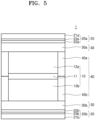
- the negative electrode layer 20 (20a and 20b) may include: a negative current collector 21 (21a and 21b); a negative active material layer 22 (22a and 22b); and a first protective layer 23 (23a and 23b) disposed between the negative current collector 21 and the first negative active material layer 22.
- the first negative active material layer 22 may include a carbonaceous material matrix and a metallic negative active material located in the carbonaceous material matrix.
- the first negative active material layer 22 may include a carbonaceous material matrix.
- the carbonaceous material matrix may include a first carbonaceous nanostructure.
- the carbonaceous nanostructure may have a nano-scale dimension and may be a structure formed of a carbonaceous material.
- the carbon nanostructure may include, for example, a one-dimensional carbon nanostructure, a two-dimensional carbon nanostructure, a three-dimensional carbon nanostructure, or any combination thereof.
- the one-dimensional carbonaceous nanostructure may include, for example, carbon nanorod, carbon nanofiber, carbon nanotube, or any combination thereof.
- the two-dimensional carbonaceous nanostructure may include, for example, carbon nanosheet, carbon nanobelt, carbon nanoflake, graphene, graphene oxide (GO), reduced graphene oxide (rGO), or any combination thereof.
- the three-dimensional carbonaceous nanostructure may be a structure in which a plurality of one-dimensional carbonaceous nanostructures and/or two-dimensional carbonaceous nanostructures are connected or stacked.
- the first carbonaceous nanostructure may include, for example, a two-dimensional nanostructure.
- the first carbonaceous nanostructure may include, for example, graphene, graphene oxide (GO), reduced graphene oxide (rGO), or any combination thereof.
- the carbonaceous material matrix may include, for example, the first carbonaceous nanostructure arranged in a direction.
- the first carbonaceous nanostructure may include, for example, graphene.
- the carbonaceous material matrix may include graphene arranged in a direction.
- the carbonaceous material matrix may include, for example, the first carbonaceous nanostructure arranged in a direction parallel to a surface of the negative current collector 21.
- the carbonaceous material matrix may include, for example, graphene.
- the carbonaceous material matrix may include, for example, graphene arranged in a direction parallel to the surface of the negative current collector 21.
- the graphene may be arranged, for example, at an angle of about -30° to about 30°, about -20° to about 20°, about -10° to about 10°, or about - 5° to about 5° with the surface of the negative current collector 21.
- the growth of lithium dendrite from the first negative active material layer 22 may more effectively be inhibited because the first carbonaceous nanostructure is arranged in a direction parallel to the surface of the negative current collector 21 in the carbonaceous material matrix.
- the carbonaceous material matrix may have a structure in which the first carbonaceous nanostructure is stacked in a thickness direction of the first negative active material layer 22.
- a plurality of first carbonaceous nanostructures may be stacked along the thickness direction of the first negative active material layer 22.
- the carbonaceous material matrix may include, for example, a plurality of first carbonaceous nanostructure layers stacked in the thickness direction of the first negative active material layer 22.
- structural density and structural stability of the first negative active material layer 22 may be improved because the first carbonaceous nanostructures are stacked in the thickness direction of the first negative active material layer 22.
- the carbonaceous material matrix may include, for example, the first carbonaceous nanostructures irregularly located without being arranged.
- the first carbonaceous nanostructure may include, for example, graphene, and the carbonaceous material matrix may include graphenes irregularly located without being arranged.
- the carbonaceous material matrix may include, for example, the first carbonaceous nanostructures irregularly and/or randomly located with respect to the surface of the negative current collector 21.
- the carbonaceous material matrix may include, for example, graphenes, and the carbonaceous material matrix may include graphenes irregularly and/or randomly located with respect to the surface of the negative current collector 21.
- Ion conduction paths and/or electron conduction paths through the first negative active material layer 22 may be diversified because the first carbonaceous nanostructures are irregularly and/or randomly located with respect to the surface of the negative current collector 21 in the carbonaceous material matrix. For example, internal resistance of the all-solid secondary battery including the carbonaceous material matrix may further be reduced.
- the carbonaceous material matrix may include, for example, crystalline carbon, amorphous carbon, or any combination thereof.
- the carbonaceous material matrix may include the first carbonaceous nanostructure, and the first carbonaceous nanostructure may include, for example, a crystalline carbon nanostructure, an amorphous carbon nanostructure, or any combination thereof.
- a carbonaceous material matrix formed of the crystalline carbon nanostructure may have high crystallinity.
- a carbonaceous material matrix formed of the amorphous carbon nanostructure may have low crystallinity. If (e.g., when) the carbonaceous material matrix includes, for example, the first carbonaceous nanostructures arranged in a direction, the carbonaceous material matrix may have high crystallinity.
- crystallinity of the first negative active material layer 22 may increase. If (e.g., when) the carbonaceous material matrix includes, for example, the first carbonaceous nanostructures irregularly located, the carbonaceous material matrix may have low crystallinity. If (e.g., when) an amount of the irregularly located first carbonaceous nanostructures increases in the carbonaceous material matrix, crystallinity of the first negative active material layer 22 may decrease. Crystallinity of the carbonaceous material matrix may be determined by utilizing, for example, a Raman spectrum, an X-ray diffraction (XRD) spectrum, high-resolution transmission electron microscope, and/or the like.
- XRD X-ray diffraction
- the carbonaceous material matrix may include the first carbonaceous nanostructure, and the first carbonaceous nanostructure may be doped with, for example, a dopant.
- the dopant may include an n-type or kind dopant, a p-type or kind dopant, or any combination thereof.
- the n-type or kind dopant having more electrons than carbon may be a dopant utilized to introduce electrons into a carbonaceous material.
- the p-type or kind dopant having less electrons than carbon may be a dopant utilized to introduce holes into the carbonaceous material.
- the first carbonaceous nanostructure may include, for example, dopant-doped graphene.
- the doped graphene may include, for example, a n-type or kind dopant, a p-type or kind dopant, or any combination thereof.
- the dopant may include, for example, nitrogen (N), phosphorus (P), boron (B), sulfur (S), fluorine (F), chlorine (Cl), bromine (Br), germanium (Ge), gallium (Ga), or any combination thereof.
- nitrogen (N) and phosphorus (P) may be n-type or kind dopants.
- gallium (Ga) may be a p-type or kind dopant.
- An amount of the dopant included in the doped first carbonaceous nanostructure may be, for example, 3 at% or less, 2 at% or less, 1 at% or less, or 0.5 at% or less.
- Conductivity of the first carbonaceous nanostructure may further be improved because the first carbonaceous nanostructure is doped with the dopant.
- Internal resistance of the first negative active material layer 22 may decrease and interfacial resistance between the first negative active material layer 22 and the solid electrolyte layer 30 may further be reduced because the carbonaceous material matrix includes the doped first carbonaceous nanostructures. As a result, the all-solid secondary battery may have reduced internal resistance and further improved higher rate characteristics.
- the carbonaceous material matrix may not include (e.g., may exclude) the binder. If (e.g., when) the carbonaceous material matrix does not include a binder, the first negative active material layer 22 may have reduced internal resistance and improved ionic conductivity and/or electronic conductivity. As a result, cycle characteristics such as higher rate characteristics of the all-solid secondary battery may be improved.
- the carbonaceous material matrix may further include, for example, pores located in the carbonaceous material matrix. If (e.g., when) the carbonaceous material matrix includes a plurality of first carbonaceous nanostructures and the plurality of first carbonaceous nanostructures are irregularly located therein, pores defined by the plurality of first carbonaceous nanostructures may be formed in the carbonaceous material matrix. By including, for example, the first carbonaceous nanostructures arranged in a direction, the carbonaceous material matrix may have low porosity. If (e.g., when) an amount of the first carbonaceous nanostructures arranged in a direction increases in the carbonaceous material matrix, the number of pores included in the carbonaceous material matrix may decrease.
- the first negative active material layer 22 may have reduced porosity.
- the porosity of the carbonaceous material matrix may increase because the carbonaceous material matrix includes, for example, the first carbonaceous nanostructures irregularly located.
- the number of pores included in the carbonaceous material matrix may increase. Therefore, the first negative active material layer 22 may include increased porosity.
- the porosity of the carbonaceous material matrix may be measured, for example, by a gas adsorption method.
- the carbonaceous material matrix may be, for example, a lithium host.
- the carbonaceous material matrix may be, for example, an electrochemically inert lithium host.
- the electrochemically inert lithium host may be a lithium host acting as a conductor for electron conduction and/or a receptor for receiving plated lithium without forming a compound via reaction with lithium. Deterioration of the all-solid secondary battery 1 caused by changes of a volume and/or physical properties of the first negative active material layer 22 during charging and discharging may more effectively be inhibited because the carbonaceous material matrix acts as the electrochemically inert lithium host. Therefore, electron conduction and/or lithium plating may more effectively be performed in the first negative active material layer 22 because the carbonaceous material matrix acts as an electrochemically inert lithium host.
- the carbonaceous material matrix may be, for example, an electrochemically active lithium host.
- the electrochemically active lithium host may be a lithium host reacting with lithium to form a compound. If (e.g., when) the carbonaceous material matrix acts as the electrochemically active lithium host, non-uniform plating of lithium may more effectively prevented or reduced in the first negative active material layer 22, and thus cycle characteristics of the all-solid secondary battery 1 may further be improved. Therefore, lithium may be uniformly plated in the first negative active material layer 22 because the carbonaceous material matrix acts as the electrochemically active lithium host. Lithium metal may be plated in the pores because the carbonaceous material matrix further has pores.
- the negative electrode layer 20 may include: a negative current collector 21; and a first negative active material layer 22 disposed on the negative current collector 21.
- the first negative active material layer 22 may include a metallic negative active material located in the carbonaceous material matrix.
- the metallic negative active material may be a negative active material capable of forming an alloy or compound with lithium.
- the metallic negative active material may include, for example, at least one alloy-forming element selected from among gold (Au), platinum (Pt), palladium (Pd), silicon (Si), silver (Ag), aluminum (Al), bismuth (Bi), tin (Sn), and zinc (Zn), but is not limited thereto, and any materials commonly utilized in the art as metallic negative active material capable of forming an alloy or compound with lithium may also be utilized.
- nickel (Ni) may not be a metallic negative active material, because Ni does not form an alloy with lithium.
- the metallic negative active material may not include (e.g., may exclude) a metal oxide.
- the metallic negative active material may include, for example, a metal capable of forming an alloy or compound with lithium, but may not include (e.g., may exclude) an oxide of the metal.
- the metallic negative active material may include, for example, silver (Ag), but may not include (e.g., may exclude) an oxide (e.g., Ag 2 O) of silver (Ag).
- the metallic negative active material may be, for example, a composite negative active material having a core/shell structure.
- the metallic negative active material may include: for example, a core; and a shell the disposed on the surface of the core.
- the shell may cover the core in whole or in part.
- the core may include, for example, a metal capable of forming an alloy or compound with lithium.
- the metal capable of forming an alloy or compound with lithium may include, for example, at least one ally-forming element selected from among gold (Au), platinum (Pt), palladium (Pd), silicon (Si), silver (Ag), aluminum (Al), bismuth (Bi), tin (Sn), and zinc (Zn).
- the shell may include, for example, a carbonaceous material.
- the shell may include, for example, a third carbonaceous nanostructure.
- the third carbonaceous nanostructure may be, for example, a carbonaceous nanostructure identical to the first carbonaceous nanostructure.
- the third carbonaceous nanostructure may include, for example, graphene, graphene oxide, reduced graphene oxide, or any combination thereof.
- the third carbonaceous nanostructure may be distinguished from the first carbonaceous nanostructure included in the carbonaceous material matrix in terms of the composition and physical properties such as thickness, position, and crystallinity.
- the third carbonaceous nanostructure may constitute the shell of the metallic negative active material and may be distinguished from the carbonaceous material matrix.
- the metallic negative active material may have, for example, a structure including a metal core including a metal capable of forming an alloy or compound with lithium; and a shell including the third carbonaceous nanostructure disposed on the core.
- the metallic negative active material may have, for example, a structure including a metal core including a metal capable of forming an alloy or compound with lithium; and a shell including graphene disposed on the core.
- the shell may include, for example, amorphous carbon. If (e.g., when) the shell includes amorphous carbon, ion conduction and/or electron conduction between the core and the carbonaceous material matrix may more easily be performed.
- the shell may be, for example, a coating layer of amorphous carbon disposed on the core.
- the metallic negative active material may have, for example, a structure including: a metal core including a metal capable of forming an alloy or compound with lithium; and a shell including amorphous carbon disposed on the core.
- the metallic negative active material may have, for example, a structure including: a metal core including a metal capable of forming an alloy or compound with lithium; and an amorphous carbon coating layer disposed on the core.
- the metallic negative active material may be, for example, in the form of particles.
- the metallic negative active material in the form of particles may have a particle diameter of, for example, about 2 ⁇ m or less, about 1.5 ⁇ m or less, about 1 ⁇ m or less, about 0.5 ⁇ m or less, or about 100 nm or less.
- the particle diameter of the metallic negative active material in the form of particles may be, for example, from about 1 nm to about 2 ⁇ m, from about 1 nm to about 1.5 ⁇ m, from about 5 nm to about 1 ⁇ m, from about 10 nm to about 500 nm, from about 10 nm to about 400 nm, from about 10 nm to about 200 nm, or from about 10 nm to about 100 nm.
- the metallic negative active material may be a reduced product of a metallic negative active material precursor.
- the metallic negative active material may be a reduced product of a metal ion.
- the metallic negative active material may be distributed in a uniformly dispersed state without aggregating because the metallic negative active material is a reduced product of the metal ion.
- the particle diameter of the metallic negative active material may be, for example, an arithmetic average of particle diameters of the metallic negative active material obtained by analyzing cross-sectional images of the first negative active material layer 22 obtained by an electron microscope utilizing software or manually.
- Particles of the metallic negative active material may include a core and a shell disposed on the surface of the core.
- a particle diameter of the core may be, for example, from about 1 nm to about 1 ⁇ m, from about 10 nm to about 500 nm, from about 10 nm to about 400 nm, from about 10 nm to about 300 nm, from about 10 nm to about 200 nm, or from about 10 nm to about 100 nm.
- the shell may have a thickness of, for example, 100 nm or less, 50 nm or less, 40 nm or less, 30 nm or less, 20 nm or less, or 10 nm or less.
- the thickness of the shell may be, for example, from about 1 nm to about 100 nm, from about 1 nm to about 50 nm, from about 1 nm to about 40 nm, from about 1 nm to about 30 nm, from about 1 nm to about 20 nm, or from about 1 nm to about 10 nm. If (e.g., when) the particle diameters and the thicknesses of the core and the shell are within the ranges described above, cycle characteristics of the all-solid secondary battery 1 including particles of the metallic negative active material may be improved.
- An amount of the metallic negative active material may be 10 parts by weight or less, 5 parts by weight or less, 3 parts by weight or less, or 2 parts by weight or less based on 100 parts by weight of the carbonaceous material matrix.
- the amount of the metallic negative active material may be from about 0.1 parts by weight to about 10 parts by weight, from about 0.5 parts by weight to about 5 parts by weight, from about 0.5 parts by weight to about 3 parts by weight, or from about 0.5 parts by weight to about 2 parts by weight based on 100 parts by weight of the carbonaceous material matrix.
- Cycle characteristics of the all-solid secondary battery 1 may further be improved because the amount of the metallic negative active material is within the range described above.
- the first negative active material layer 22 utilized in the all-solid secondary batteries 1 of FIGS. 1 to 5 may have a reduced amount of the metallic negative active material.
- An all-solid secondary battery 1 having excellent or suitable cycle characteristics with a relatively low amount of the metallic negative active material may be provided because the first negative active material layer 22 includes the metallic negative active material dispersed in the carbonaceous material matrix by a dry method.
- the carbonaceous material matrix may further include a carbonaceous negative active material located in the carbonaceous material matrix.
- the carbonaceous negative active material may be, for example, amorphous carbon.
- the amorphous carbon may be, for example, carbon black (CB), acetylene black (AB), furnace black (FB), or Ketjen black (KB), but is not limited thereto, and any carbon classified as amorphous carbon in the art may also be utilized.
- Amorphous carbon may be carbon that does not have crystallinity or has very low crystallinity and may be distinguished from crystalline carbon or graphite-based carbon.
- the carbonaceous negative active material may not need to be provided (e.g., may be excluded).
- Negative Electrode Layer First Negative Active Material Layer
- a thickness of the first negative active material layer 22 may be, for example, 50 % or less, 40 % or less, 30 % or less, 20 % or less, 10 % or less, or 5 % or less of a thickness of the positive active material layer 12.
- the thickness of the first negative active material layer 22 may be, for example, 20 ⁇ m or less, 10 ⁇ m or less, 7 ⁇ m or less, or 5 ⁇ m or less.
- the thickness of the first negative active material layer 22 may be, for example, from about 1 ⁇ m to about 20 ⁇ m, from about 2 ⁇ m to about 10 ⁇ m, from about 2 ⁇ m to about 7 ⁇ m, or from about 2 ⁇ m to about 5 ⁇ m.
- lithium dendrite formed between the first negative active material layer 22 and the negative current collector 21 may break the first negative active material layer 22, making it difficult to improve cycle characteristics of the all-solid secondary battery 1. If (e.g., when) the first negative active material layer 22 is too thick, energy density of the all-solid secondary battery 1 may decrease, internal resistance of the all-solid secondary battery 1 may be increased by the first negative active material layer 22, making it difficult to improve cycle characteristics of the all-solid secondary battery 1.
- a charging capacity of the first negative active material layer 22 may also decrease.
- the charging capacity of the first negative active material layer 22 may be, for example, 50 % or less, 40 % or less, 30 % or less, 20 % or less, 10 % or less, 5 % or less, or 2 % or less of a charging capacity of the positive active material layer 12.
- the charging capacity of the first negative active material layer 22 may be, for example, from about 0.1 % to about 50 %, from about 0.1 % to about 40 %, from about 0.1 % to about 30 %, from about 0.1 % to about 20 %, from about 0.1 % to about 10%, from about 0.1 % to about 5 %, or from about 0.1 % about to 2 % based on the charging capacity of the positive active material layer 12.
- the thickness of the first negative active material layer 22 may become too small, and thus lithium dendrite formed between the first negative active material layer 22 and the negative current collector 21 during repeated charging and discharging processes may break the first negative active material layer 22, making it difficult to improve cycle characteristics of the all-solid secondary battery 1.
- the charging capacity of the first negative active material layer 22 is too high, energy density of the all-solid secondary battery 1 may decrease, and thus internal resistance of the all-solid secondary battery 1 may be increased by the first negative active material layer 22, making it difficult to improve cycle characteristics of the all-solid secondary battery 1.
- a ratio (C1/C2) of the charging capacity C1 of the first negative active material layer 22 to the charging capacity C2 of the positive active material layer 12 may be, for example, from about 0.001 to about 0.45, from about 0.001 to about 0.4, from about 0.001 to about 0.3, from about 0.001 to about 0.25, from about 0.001 to about 0.2, from about 0.001 to about 0.1, from about 0.001 to about 0.05, or from about 0.001 to about 0.02.
- the charging capacity of the positive active material layer 12 may be obtained by multiplying a charging capacity density (mAh/g) of the positive active material by a mass of the positive active material of the positive active material layer 12.
- charging capacity density ⁇ mass values of all of the positive active materials may be calculated respectively, and a sum of the values may be regarded as the charging capacity of the positive active material layer 12.
- the charging capacity of the first negative active material layer 22 may be calculated in substantially the same manner.
- the charging capacity of the first negative active material layer 22 may be obtained by multiplying a charging capacity density (mAh/g) of the negative active material by a mass of the negative active material of the first negative active material layer 22.
- charging capacity density ⁇ mass values of all of the negative active materials may be calculated respectively, and a sum of the values may be regarded as the charging capacity of the first negative active material layer 22.
- the charging capacity densities of the positive active material and the negative active material may be capacities estimated utilizing all-solid half-cells to which lithium metal is applied as a counter electrode.
- the charging capacities of the positive active material layer 12 and the first negative active material layer 22 may directly be measured utilizing the all-solid half-cells.
- the charging capacity density may be calculated by dividing the measured charging capacity by the mass of each active material.
- the charging capacity of the positive active material layer 12 and the first negative active material layer 22 may be an initial charging capacity measured during charging of a first cycle.
- the first negative active material layer 22 may be free from a binder.
- the first negative active material layer 22 may not include (e.g., may exclude) a binder because the first negative active material layer 22 is formed by a dry method.
- the first negative active material layer 22 may have improved electronic conductivity and/or ionic conductivity and reduced internal resistance because the first negative active material layer 22 does not include a binder. Therefore, cycle characteristics, such as higher rate characteristics, of the all-solid secondary battery 1 including the first negative active material layer 22 may be improved.
- the first negative active material layer may be prepared by a dry method such as chemical vapor deposition (CVD) or physical vapor deposition (PVD).
- CVD chemical vapor deposition
- PVD physical vapor deposition
- the first negative active material layer 22 may have a thickness greater than that of the first protective layer 23 (23a and 23b).
- the thickness of the first negative active material layer 22 may be 150 % or more, 200 % or more, 300 % or more, or 500 % or more than that of the first protective layer 23 (23a and 23b). If (e.g., when) the first negative active material layer 22 has a thickness within the ranges described above, the thickness of the first protective layer 23 (23a and 23b) relatively decreases, and thus energy density of the all-solid secondary battery may further be improved.
- a peak intensity ratio (I D /I G ) of D-band peak intensity (I D ) at about 1350 cm -1 derived from amorphous carbon to G-band peak intensity (I G ) at about 1580 cm -1 derived from crystalline carbon may be, for example, about 20 or less, about 15 or less, about 10 or less, about 5 or less, about 3 or less, about 2 or less, about 1 or less, about 0.8 or less, or about 0.5 or less.
- the peak intensity ratio (I D /I G ) of D-band peak intensity (I D ) at about 1350 cm -1 derived from amorphous carbon to G-band peak intensity (I G ) at about 1580 cm -1 derived from crystalline carbon may be, for example, greater than about 0, about 0.01 or more, about 0.05 or more, about 0.1 or more, about 0.3 or more, about 0.5 or more, or about 1 or more.
- the peak intensity ratio (I D /I G ) of D-band peak intensity (I D ) at about 1350 cm -1 derived from amorphous carbon to G-band peak intensity (I G ) at about 1580 cm -1 derived from crystalline carbon may be, for example, greater than about 0 to but not more than about 20, greater than about 0 but not more than about 15, greater than about 0 but not more than about 10, from about 0.01 to about 10, from about 0.01 to about 5, from about 0.1 to about 5, from about 0.1 to about 3, or from about 0.1 to about 1.
- the peak intensity ratio (I D /I G ) of D-band peak intensity (I D ) at about 1350 cm -1 derived from amorphous carbon to G-band peak intensity (I G ) at about 1580 cm -1 derived from crystalline carbon may be, for example, from about 0.1 to about 10, from about 0.5 to about 5, from about 1 to about 3, or from about 1 to about 2.
- the peak intensity ratio (I D /I G ) of D-band peak intensity (I D ) at about 1350 cm -1 derived from amorphous carbon to G-band peak intensity (I G ) at about 1580 cm -1 derived from crystalline carbon may be, for example, from about 0.5 to about 10, from about 1 to about 5, from about 2 to about 5, or from about 3 to about 5.
- the Raman spectrum may be obtained from the first negative active material layer 22 and the first protective layer 23 of the negative electrode layer 20. If (e.g., when) the negative electrode layer 20 has the peak intensity ratio within the ranges described above, deterioration of the negative current collector 21 caused by the solid electrolyte may be inhibited more effectively.
- a negative electrode layer 20 including a nickel negative current collector 21 may have a relatively lower peak intensity ratio than that of the negative electrode layer 20 including a copper negative current collector 21.
- a porosity of the negative electrode layer 20 obtained by utilizing a nitrogen gas adsorption method may be, for example, about 30 % or less, about 20 % or less, about 15 % or less, about 10 % or less, about 5 % or less, about 3 % or less, about 2 % or less, about 1 % or less, about 0.8 % or less, or about 0.5 % or less.
- the porosity of the negative electrode layer 20 obtained by utilizing the nitrogen gas adsorption method may be, for example, greater than about 0 %, about 0.1 % or more, or about 0.5 % or more.
- the porosity of the negative electrode layer 20 obtained by utilizing the nitrogen gas adsorption method may be, for example, greater than about 0 % but not more than about 30 %, greater than about 0 % but not more than about 20 %, from about 0.01 % to about 10 %, from about 0.1 % to about 5 %, from about 0.5 % to about 5 %, or from about 1 % to about 5 %.
- the porosity of the negative electrode layer 20 obtained by utilizing the nitrogen gas adsorption method (multi-point BET) may be, for example, from about 0.1 % to about 20 %, from about 1 % to about 10 %, or from about 5 % to about 10 %.
- the porosity of the negative electrode layer 20 obtained by utilizing the nitrogen gas adsorption method may be, for example, from about 1 % to about 20 %, from about 5 % to 20 %, or from about 10 % to 20 %. If (e.g., when) the porosity of the negative electrode layer 20 is within the ranges described above, deterioration of the negative current collector 21 caused by the solid electrolyte may be prevented or reduced more effectively. If (e.g., when) the porosity of the negative electrode layer 20 excessively increases, it may be difficult to effectively prevent or reduce deterioration of the negative current collector 21 caused by the solid electrolyte.
- Negative Electrode Layer First Protective Layer
- the negative electrode layer 20 may include: a negative current collector 21; a first negative active material layer 22; and a first protective layer 23 (23a and 23b) disposed between the negative current collector 21 and the first negative active material layer 22.
- the first protective layer 23 (23a and 23b) may be, for example, a conductive coating layer including a carbonaceous material.
- the first protective layer 23 (23a and 23b) includes, for example, a second carbonaceous nanostructure.
- the carbonaceous nanostructure may have a nano-scale dimension and may be a structure formed of a carbonaceous material.
- the carbon nanostructure may include, for example, a one-dimensional carbon nanostructure, a two-dimensional carbon nanostructure, a three-dimensional carbon nanostructure, or any combination thereof.
- the second carbonaceous nanostructure may include, for example, a two-dimensional nanostructure.
- the second carbonaceous nanostructure may include, for example, graphene, graphene oxide (GO), reduced graphene oxide (rGO), or any combination thereof.
- the second carbonaceous nanostructure may be selected from the previously-described first carbonaceous nanostructures.
- the second carbonaceous nanostructure may be doped with a dopant.
- the dopant-doped second carbonaceous nanostructure may be selected from the first carbonaceous nanostructures doped with a dopant.
- the first protective layer 23 may include, for example, the second carbonaceous nanostructure arranged in a direction with respect to the surface of the negative current collector 21.
- the second carbonaceous nanostructure may include, for example, graphene.
- the first protective layer 23 (23a and 23b) may include graphene arranged in a direction with respect to the surface of the negative current collector 21.
- the first protective layer 23 may include, for example, the second carbonaceous nanostructures arranged in a direction parallel to the surface of the negative current collector 21.
- the second carbonaceous nanostructure may be arranged in a direction parallel to the surface of the negative current collector 21.
- the first protective layer 23 (23a and 23b) may include, for example, graphene.
- the first protective layer 23 (23a and 23b) may include graphene arranged in a direction parallel to the surface of the negative current collector 21.
- the graphene may be arranged, for example, at an angle of about -30° to about 30°, about -20° to about 20°, about -10° to about 10°, or about -5° to about 5° with the surface of the negative current collector 21.
- the contact between the solid electrolyte and the negative current collector 21 may be inhibited more effectively because the second carbonaceous nanostructures is arranged in a direction parallel to the surface of the negative current collector 21 in the first protective layer 23 (23a and 23b).
- the first protective layer 23 may include, for example, the second carbonaceous nanostructures arranged in a direction protruding from the surface of the negative current collector 21.
- the second carbonaceous nanostructures may be arranged in a direction protruding from the surface of the negative current collector 21.
- the first protective layer 23 (23a and 23b) may include, for example, graphene.
- the first protective layer 23 (23a and 23b) may include graphene arranged in a direction protruding from the surface of the negative current collector 21.
- the second carbonaceous nanostructure may be arranged, for example, at an angle of about 45° to about 135°, about 50° to about 130°, about 60° to about 120°, about 70° to about 110°, or about 80° to about 100° with respect to the surface of the negative current collector 21.
- the second carbonaceous nanostructure may be arranged, for example, to be substantially perpendicular or normal to the surface of the negative current collector 21. If (e.g., when) the second carbonaceous nanostructures may be arranged in the direction protruding from the surface of the negative current collector 21 in the first protective layer 23 (23a and 23b), electron conduction between the first negative active material layer 22 and the negative current collector 21 may be performed more easily. As a result, an increase in internal resistance in the all-solid secondary battery 1 may be inhibited more effectively.
- the first protective layer 23 may have a structure in which the second carbonaceous nanostructure is stacked in a thickness direction of the first protective layer 23 (23a and 23b).
- a plurality of second carbonaceous nanostructures may be stacked along the thickness direction of the first protective layer 23 (23a and 23b).
- the first protective layer 23 (23a and 23b) may include, for example, a plurality of second carbonaceous nanostructure layers stacked in the thickness direction of the first protective layer 23 (23a and 23b).
- Structural density and structural stability of the first protective layer 23 (23a and 23b) may further be improved because the second carbonaceous nanostructures are stacked in the thickness direction of the negative current collector 21 in the first protective layer 23 (23a and 23b).
- the second carbonaceous nanostructure may be stacked, for example, up to about 2000 layers, up to about 1500 layers, up to about 1000 layers, up to about 500 layers, up to about 100 layers, up to about 70 layers, up to about 50 layers, or up to about 30 layers in the first protective layer 23 (23a and 23b).
- the second carbonaceous nanostructures may be stacked, for example, from about 1 layer to about 100 layers, from about 5 layers to about 70 layers, from about 10 layers to about 50 layers, or from about 20 layers to about 30 layers in the first protective layer 23 (23a and 23b).
- the second carbonaceous nanostructures may be stacked, for example, from about 1 layer to about 2000 layers, from about 10 layers to about 1000 layers, from about 100 layers to about 1000 layers, from about 100 layers to about 500 layers, or from about 100 layers to about 300 layers in the first protective layer 23 (23a and 23b).
- the second carbonaceous nanostructures may be stacked, for example, from about 1 layer to about 2000 layers, from about 10 layers to about 2000 layers, from about 100 layers to about 2000 layers, from about 500 layers to about 2000 layers, or from about 1000 layers to about 2000 layers in the first protective layer 23 (23a and 23b). Structural stability of the first protective layer 23 (23a and 23b) may further be improved because the number of stacked layers of the second carbonaceous nanostructure is within the ranges above.
- the first protective layer 23 may directly be disposed on one side of the negative current collector 21.
- the first protective layer 23 (23a and 23b) may be inert to a solid electrolyte, for example, a sulfide-based solid electrolyte.
- the contact between the negative current collector 21 and the sulfide-based solid electrolyte may be blocked by directly disposing the first protective layer 23 (23a and 23b) on one side of the negative current collector 21, and thus deterioration, such as corrosion, of the negative current collector 21 may be prevented or reduced more effectively.
- the first protective layer 23 may be disposed, for example, on one side of the negative current collector 21 facing the solid electrolyte layer.
- the first protective layer 23 (23a and 23b) may also be disposed on the other side of the negative current collector 21 opposing to the one side of the negative current collector 21 and may also be disposed on side surfaces of the negative current collector 21 between the one side and the other sides. Deterioration caused by the sulfide-based solid electrolyte may more effectively be inhibited because the first protective layer 23 (23a and 23b) convers the negative current collector 21 in part or in whole. Therefore, lifespan characteristics of the all-solid secondary battery 1 including the first protective layer 23 (23a and 23b) may be improved.
- the first protective layer 23 may have a thickness of, for example, about 5 ⁇ m or less, about 3 ⁇ m or less, about 2 ⁇ m or less, about 1.5 ⁇ m or less, about 1 ⁇ m or less, about 500 nm or less, about 300 nm or less, or about 100 nm or less.
- the thickness of the first protective layer 23 (23a and 23b) may be, for example, at least a thickness of a single graphene layer, about 1 nm or more, about 10 nm or more, about 20 nm or more, about 50 nm or more, or about 100 nm or more.
- the thickness of the first protective layer 23 may be, for example, from about the thickness of the single graphene layer to about 2 ⁇ m, from about 10 nm to about 1.5 ⁇ m, from about 50 nm to about 1 ⁇ m, from about 100 nm to about 900 nm, from about 200 nm to about 800 nm, or from about 300 nm to about 700 nm.
- the thickness of the first protective layer 23 may be, for example, from about the thickness of the single graphene layer to about 2 ⁇ m, from about 1 nm to about 1.5 ⁇ m, from about 5 nm to about 1 ⁇ m, from about 10 nm to about 500 nm, from about 20 nm to about 300 nm, or from about 20 nm to about 100 nm. If (e.g., when) the first protective layer 23 (23a and 23b) is too thick, the all-solid secondary battery may have increased internal resistance and decreased energy density. If (e.g., when) the first protective layer 23 (23a and 23b) is too thin, it may be difficult to effectively prevent or reduce side reactions between the negative current collector 21 and the solid electrolyte.
- the first protective layer 23 (23a and 23b) may be free from a binder.
- the first protective layer 23 (23a and 23b) may not include (e.g., may exclude) a binder because the first protective layer 23 (23a and 23b) is formed by a dry method.
- the first protective layer 23 (23a and 23b) may have improved electronic conductivity and reduced internal resistance because the first protective layer 23 (23a and 23b) does not include a binder. Therefore, the all-solid secondary battery 1 including the first protective layer 23 (23a and 23b) may have improved cycle characteristics, such as higher rate characteristics.
- the first protective layer 23 (23a and 23b) may be prepared by a dry method such as CVD and PVD.
- the dry method utilized to form the first protective layer 23 (23a and 23b is not limited and any dry methods without utilizing a binder commonly utilized in the art may also be utilized.
- the first protective layer 23 (23a and 23b) may be formed of, for example, the second carbonaceous nanostructure and may not include (e.g., may exclude) a binder.
- the first protective layer 23 (23a and 23b) may be formed of, for example, graphene, and may not include (e.g., may exclude) a binder.
- the negative current collector 21 may be formed of, for example, a material that does not react with lithium, i.e., a material that does not form an alloy and compound with lithium.
- a material utilized to form the negative current collector 21 may be, for example, copper (Cu), indium (In), magnesium (Mg), titanium (Ti), iron (Fe), cobalt (Co), nickel (Ni), zinc (Zn), aluminum (Al), germanium (Ge), or chromium (Cr), but is not limited thereto, and any materials commonly utilized in the art as an electrode current collector may also be utilized.
- the negative current collector 21 may be formed of one metal selected from those described above or an alloy or coating material of two or more metals selected therefrom.
- the negative current collector 21 may be, for example, in the form of a plate or foil.
- the negative current collector 21 may include, for example, a base film and a metal layer disposed on at least one side (e.g., one or both (e.g., opposite) sides) of the base film.
- the base film may include, for example, a polymer.
- the polymer may be, for example, a thermoplastic polymer.
- the polymer may include, for example, polyethyleneterephthalate (PET), polyethylene (PE), polypropylene (PP), polybutyleneterephthalate (PBT), polyimide (PI), or any combination thereof. If (e.g., when) a short circuit occurs, the base film including the thermoplastic polymer melts, and thus a rapid current increase may be inhibited.
- the base film may be, for example, an insulator.
- the metal layer may include, for example, indium (In), copper (Cu), magnesium (Mg), titanium (Ti), iron (Fe), cobalt (Co), nickel (Ni), zinc (Zn), aluminum (Al), germanium (Ge), or an alloy thereof.
- the metal layer may include, for example, copper (Cu), titanium (Ti), iron (Fe), cobalt (Co), nickel (Ni), or an alloy thereof.
- the metal layer may act as an electrochemical fuse to be cut if (e.g., when) an overcurrent occurs, thereby preventing or reducing a short circuit. By controlling a thickness of the metal layer, a limiting current and a maximum current may be adjusted.
- the metal layer may be plated or deposited on the base film.
- a lead tab may be added onto the metal layer for connection with the outside.
- the lead tab may be welded to the metal layer or a metal layer/base film stack structure by ultrasonic welding, laser welding, spot welding, and/or the like. While the base film and/or the metal layer melts during welding, the metal layer may be electrically connected to the lead tab.
- a metal chip may further be added between the metal layer and the lead tab for stronger welding between the metal layer and the lead tab.
- the metal chip may be a chip of the same material as the metal of the metal layer.
- the metal chip may be, for example, metal foil and metal mesh.
- the metal chip may be, for example, copper foil and nickel foil.
- the lead tab may be welded to a metal chip/metal layer stack structure or a metal chip/metal layer/base film stack structure. While the base film, the metal layer, and/or the metal chip melt during welding, the metal layer or the metal layer/metal chip stack structure may be electrically connected to the lead tab.
- a metal chip and/or a lead tab may further be added to a portion of the metal layer.
- the base film may have a thickness of, for example, about 1 ⁇ m to about 50 ⁇ m, about 1.5 ⁇ m to about 50 ⁇ m, about 1.5 ⁇ m to about 40 ⁇ m, or about 1 ⁇ m to about 30 ⁇ m. If (e.g., when) the thickness of the base film is within the previously-described ranges, the weight of the electrode assembly may be reduced more effectively.
- a melting point of the base film may be, for example, from about 100 °C to about 300 °C, from about 100 °C to about 250 °C, or from about 100 °C to about 200 °C.
- a thickness of the metal layer may be, for example, from about 0.01 ⁇ m to about 3 ⁇ m, from about 0.1 ⁇ m to about 3 ⁇ m, from about 0.1 ⁇ m to about 2 ⁇ m, or from about 0.1 ⁇ m to about 1 ⁇ m. If (e.g., when) the thickness of the metal layer is within the previously-described ranges, stability of the electrode assembly may be obtained while maintaining conductivity thereof.
- a thickness of the metal chip may be, for example, from about 2 ⁇ m to about 10 ⁇ m, from about 2 ⁇ m to about 7 ⁇ m, or from about 4 ⁇ m to about 6 ⁇ m. If (e.g., when) the thickness of the metal chip is within the previously-described ranges, the metal layer may be connected to the lead tab more easily. If (e.g., when) the negative current collector 21 has the previously-described structure, the weight of the negative electrode may be reduced, so that energy density of the all-solid secondary battery may be increased.
- the negative current collector 21 may further include, for example, a thin film including elements capable of forming an alloy with lithium on the negative current collector 21.
- the thin film may be disposed between the negative current collector 21 and the first negative active material layer 22.
- the thin film may include, for example, an element capable of forming an alloy with lithium. Examples of the element capable of forming an alloy with lithium may include gold, silver, zinc, tin, indium, silicon, aluminum, and bismuth, but are not limited thereto, and any elements capable of forming an alloy with lithium suitable in the art may also be utilized.
- the thin film may be formed of any one of the metals or an alloy of one or more suitable types (kinds) of metals.
- the second negative active material layer plated between the thin film and the first negative active material layer 22 may become flatter, thereby further improving cycle characteristics of the all-solid secondary battery 1.
- the thin film may be disposed between the first protective layer 23 and the first negative active material layer 22 or between the first protective layer 23 and the negative current collector 21.
- the thickness of the thin film may be, for example, from about 1 nm to about 800 nm, from about 10 nm to about 500 nm, or from about 50 nm to about 100 nm. If (e.g., when) the thickness of the thin film is less than about 1 nm, the function of the thin film may be difficult to obtain. If (e.g., when) the thin film is too thick, the thin film may irreversibly absorb lithium and thus an amount of plated lithium may be reduced in the negative electrode layer 20. As a result, substantial energy density of the all-solid secondary battery 1 may decrease and cycle characteristics of the all-solid secondary battery 1 may deteriorate.
- the thin film may be formed on the negative current collector 21, for example, by vacuum deposition, sputtering, or plating. However, the method is not limited thereto and any method capable of forming a thin film and commonly utilized in the art may also be utilized.
- Negative Electrode Layer Second Negative Active Material Layer
- the all-solid secondary battery 1 may further include, for example, a second negative active material layer disposed between the solid electrolyte layer 30 and the negative current collector 21 by charging.
- the second negative active material layer may be disposed, for example, at one or more positions between the first negative active material layer 22 and the first protective layer 23 (23a and 23b) and between the first negative active material layer 22 and the solid electrolyte layer 30.
- the all-solid secondary battery 1 may further include, for example, a second negative active material layer disposed between the first negative active material layer 22 and the first protective layer 23 (23a and 23b).
- the all-solid secondary battery 1 may further include, for example, the second negative active material layer disposed between the first negative active material layer 22 and the solid electrolyte layer 30.
- the second negative active material layer may be plated between the first negative active material layer 22 and the first protective layer 23 (23a and 23b) during a charging and discharging process of the all-solid secondary battery 1.
- the second negative active material layer may be a metal layer including lithium or a lithium alloy.
- the metal layer may include lithium or a lithium alloy. Therefore, the second negative active material layer, as a metal layer including lithium, serves as a reservoir of lithium.
- the lithium alloy may be, for example, an Li-Al alloy, an Li-Sn alloy, an Li-In alloy, an Li-Ag alloy, an Li-Au alloy, an Li-Zn alloy, an Li-Ge alloy, or an Li-Si alloy, but is not limited thereto, and any lithium alloys available in the art may also be utilized.
- the second negative active material layer may be formed of one of the alloys alone, lithium, or a combination of one or more suitable types (kinds) of alloys.
- the second negative active material layer may be, for example, a plated layer.
- a thickness of the second negative active material layer is not limited, but may be, for example, from about 1 ⁇ m to about 200 ⁇ m, from about 1 ⁇ m to about 150 ⁇ m, from about 1 ⁇ m to about 100 ⁇ m, or from about 1 ⁇ m to about 50 ⁇ m. If (e.g., when) the second negative active material layer is too thin, the function of the second negative active material layer as a reservoir of lithium may be difficult to obtain. If (e.g., when) the second negative active material layer is too thick, the mass and volume of the all-solid secondary battery 1 may increase, and thus cycle characteristics of the all-solid secondary battery 1 may deteriorate.
- the second negative active material layer may be, for example, a metal foil having a thickness within the ranges described above.
- the second negative active material layer may be, for example, disposed between the negative current collector 21 and the solid electrolyte layer 30 before assembling the all-solid secondary battery 1 or plated between the negative current collector 21 and the solid electrolyte layer 30 after assembling and charging the all-solid secondary battery 1.
- the second negative active material layer as a metal layer including lithium, may act as a lithium reservoir.
- a lithium foil may be disposed between the negative current collector 21 and the solid electrolyte layer 30 before assembling the all-solid secondary battery 1.
- cycle characteristics of the all-solid secondary battery 1 including the second negative active material layer may further be improved.
- energy density of the all-solid secondary battery 1 may increase because the second negative active material layer is not included while the all-solid secondary battery is assembled.
- charging may be performed to exceed a charging capacity of the first negative active material layer 22.
- the first negative active material layer 22 may be overcharged.
- lithium may be absorbed to the first negative active material layer 22.
- the negative active material included in the first negative active material layer 22 may form an alloy or compound with lithium ions that have migrated from the positive electrode layer 10.
- lithium may be plated, for example, on a front surface and/or a rear surface of the first negative active material layer 22, i.e., between the first negative active material layer 22 and the first protective layer 23 (23a and 23b) and/or between the first negative active material layer 22 and the solid electrolyte layer 30, and a metal layer corresponding to the second negative active material layer may be formed by the plated lithium.
- the second negative active material layer may be a metal layer mainly composed of lithium (i.e., lithium metal).
- lithium of the first negative active material layer 22 and the second negative active material layer i.e., the metal layer
- the first negative active material layer 22 may cover the second negative active material layer, acting as a protective layer of the second negative active material layer, i.e., metal layer, and inhibiting the growth of lithium dendrite.
- a short circuit and capacity reduction may be inhibited in the all-solid secondary battery 1, and thus cycle characteristics of the all-solid secondary battery 1 may be improved.
- a region between the negative current collector 21 and the solid electrolyte layer 30 may be a Li-free region not including lithium (Li) in the early state of charging or after discharging the all-solid secondary battery.
- Solid Electrolyte Layer Sulfide-based Solid Electrolyte
- the solid electrolyte layer 30 may be disposed between the positive electrode layer 10 and the negative electrode layer 20.
- the solid electrolyte layer 30 may include a sulfide-based solid electrolyte.
- the sulfide-based solid electrolyte included in the solid electrolyte layer 30 may include, for example, at least one selected from among Li 2 S-P 2 S 5 , Li 2 S-P 2 S 5 -LiX, wherein X is a halogen atom, Li 2 S-P 2 S 5 -Li 2 O, Li 2 S-P 2 S 5 -Li 2 O-LiI, Li 2 S-SiS 2 , Li 2 S-SiS 2 -Lil, Li 2 S-SiS 2 -LiBr, Li 2 S-SiS 2 -LiCl, Li 2 S-SiS 2 -B 2 S 3 -LiI, Li 2 S-SiS 2 -P 2 Ss-LiI, Li 2 S-B 2 S 3 , Li 2 S-P 2 S 5 -Z m S n , wherein m and n are positive numbers and Z is Ge, Zn, or Ga, Li 2 S-GeS
- the sulfide-based solid electrolyte may be prepared by treating a starting material such as Li 2 S and P 2 S 5 by melt quenching or mechanical milling. Heat treatment may be performed after such treatment.
- the solid electrolyte may be in an amorphous state, a crystalline state, or a mixed state thereof.
- the solid electrolyte may include, for example, sulfur (S), phosphorus (P), and lithium (Li) as components among materials for the previously-described sulfide-based solid electrolyte.
- the solid electrolyte may be a material including Li 2 S-P 2 S 5 .
- a mixing molar ratio of Li 2 S to P 2 S 5 may be, for example, from about 50:50 to about 90:10.
- the sulfide-based solid electrolyte may include, for example, an argyrodite type or kind (e.g., an argyrodite) solid electrolyte represented by Formula A.
- Formula A Li + 12-n-x A n+ X 2- 6-x Y - x
- A may be P, As, Ge, Ga, Sb, Si, Sn, Al, In, Ti, V, Nb, or Ta
- X may be S, Se, or Te
- Y may be Cl, Br, I, F, CN, OCN, SCN, or N 3 , wherein 1 ⁇ n ⁇ 5 and 0 ⁇ x ⁇ 2.
- the sulfide-based solid electrolyte may be an argyrodite-type or kind compound including, for example, at least one selected from among Li 7-x PS 6-x Cl x , wherein 0 ⁇ x ⁇ 2, Li 7-x PS 6-x Br x , wherein 0 ⁇ x ⁇ 2, and Li 7-x PS 6-x I x , wherein 0 ⁇ x ⁇ 2.
- the sulfide-based solid electrolyte may be an argyrodite-type or kind compound including, for example, at least one selected from among Li 6 PS 5 Cl, Li 6 PS 5 Br, and Li 6 PS 5 I.
- the argyrodite-type or kind solid electrolyte may have a density of about 1.5 g/cc to about 2.0 g/cc. Internal resistance of the all-solid secondary battery may be reduced and penetration of the solid electrolyte layer may be effectively inhibited because the argyrodite-type or kind solid electrolyte has a density of about 1.5 g/cc or more.
- the sulfide-based solid electrolyte may have, for example, a Young's modulus of about 40 GPa or less.
- the Young's modulus of the sulfide-based solid electrolyte may be, for example, from about 5 GPa to about 40 GPa, from about 10 GPa to about 40 GPa, or from about 15 GPa to about 30 GPa.
- An average particle diameter of the sulfide-based solid electrolyte included in the solid electrolyte layer 30 may be, for example, from about 1 ⁇ m to about 50 ⁇ m, from about 3 ⁇ m to about 30 ⁇ m, or from about 3 ⁇ m to about 20 ⁇ m. If (e.g., when) the sulfide-based solid electrolyte particles have an average particle diameter within the previously-described ranges, cycle characteristics of the all-solid secondary battery may further be improved.
- the solid electrolyte layer 30 may further include a binder.
- the binder included in the solid electrolyte layer 30 may be, for example, styrene butadiene rubber (SBR), polytetrafluoroethylene, polyvinylidene fluoride, or polyethylene, but is not limited thereto, and any binders available in the art may also be utilized.
- the binder of the solid electrolyte layer 30 may be selected from binders included in the positive active material layer 12. In some embodiments, the binder may not need to be provided (e.g., may be excluded).
- the binder included in the solid electrolyte layer may include, for example, a conductive binder and/or a non-conductive binder.
- the conductive binder may be, for example, an ion-conductive binder and/or an electron-conductive binder.
- a binder having both (e.g., simultaneously) ionic conductivity and electronic conductivity may both (e.g., simultaneously) belong to the ion-conductive binder and the electron-conductive binder.
- any conductive binder available in the art may be utilized.
- the binder included in the solid electrolyte layer 30 may include, for example, a first binder.
- the first binder may be, for example, a dry binder.
- the dry binder may be, for example, a binder not impregnated, dissolved, or dispersed in a solvent.
- the dry binder may be, for example, a binder not including a solvent or not in contact with a solvent.
- the first binder may be, for example, a fibrillized binder.
- the fibrillized binder may act as a matrix in the form of fibers binding a plurality of sulfide-based solid electrolyte particles and inorganic particles included in the solid electrolyte layer while supporting the same. It may be confirmed that the fibrillized binder has a fibrous form based on an SEM image of a cross-section thereof.
- the fibrillized binder may have an aspect ratio of, for example, about 10 or more, about 20 or more, about 50 or more, or about 100 or more.
- the first binder may be, for example, polytetrafluoroethylene (PTFE) or a polyvinylidene fluoride-hexafluoropropylene (PVDF-HFP) copolymer, but is not limited thereto, and any fibrillized binders utilized to prepare a dry composition may also be utilized.
- the first binder may include a fluorine-based binder.
- the fluorine-based binder may be, for example, polytetrafluoroethylene (PTFE).
- the aspect ratio of the fibrilized binder e.g., a ratio of diameter and length of the fibrilized binder may be determined from SEM images.
- the binder included in the solid electrolyte layer 30 may include, for example, a second binder.
- the second binder may be, for example, a dry binder. Descriptions of the dry binder are as described above in the first binder.
- the second binder may be, for example, a non-fibrillized binder.
- the non-fibrillized binder may serve as a site for binding of the sulfide-based solid electrolyte particles and inorganic particles included in the solid electrolyte layer while supporting the same. It may be confirmed that the non-fibrillized binder is in the form of particles, rather than in the form of fibers, based on a cross-sectional image of the electrode obtained by utilizing a scanning electron microscope.
- the non-fibrillized binder may have, for example, an aspect ratio of about 5 or less, about 3 or less, or about 2 or less.
- the second binder may include polyvinylidene fluoride (PVDF), polyvinyl alcohol, polyacrylonitrile, carboxymethylcellulose (CMC), starch, hydroxypropylcellulose, cellulose, polyvinylpyrrolidone, polyethylene, polypropylene, ethylene-propylene-diene polymer (EPDM), sulfonated-EPDM, styrene butadiene rubber (SBR), fluororubber, or a copolymer thereof, but are not limited thereto, and any binders utilized in the manufacture of dry electrodes may also be utilized.
- the second binder may include a fluorine-based binder.
- the fluorine-based binder may be, for example, polyvinylidene fluoride (PVDF).
- An amount of the binder included in the solid electrolyte layer 30 may be, for example, from about 1 wt% to about 10 wt%, from about 1 wt% to about 5 wt%, or from about 1 wt% to about 3 wt% based on a total weight of the solid electrolyte layer. If (e.g., when) the amount of the binder included in the solid electrolyte layer is within the ranges described above, binding strength of the solid electrolyte layer may be improved and the all-solid secondary battery may have an energy density maintained at a high level.
- the solid electrolyte layer 30 may be, for example, a self-standing film.
- the solid electrolyte layer may have a film shape without utilizing a support. Therefore, the solid electrolyte layer may be prepared as a separate self-standing film and then disposed between the positive electrode layer and the negative electrode layer.
- the solid electrolyte layer may be, for example, free from a residual processing solvent.
- the solid electrolyte layer does not include a processing solvent intentionally added thereto because the solid electrolyte layer is prepared by a dry method.
- the solid electrolyte layer does not include a residual processing solvent. A trace amount of unintended solvent may remain in the solid electrolyte layer, but the solvent may not be an intentionally added processing solvent. Therefore, the solid electrolyte layer may be distinguished from a wet solid electrolyte layer prepared by mixing sulfide-based solid electrolyte particles with a processing solvent, and drying the mixture to remove the processing solvent in part or in whole.
- Positive Electrode Layer Positive Active Material
- the positive active material layer 12 may include, for example, a positive active material and a solid electrolyte.
- the solid electrolyte included in the positive active material layer 12 may be selected from the solid electrolytes included in the solid electrolyte layer 30.
- the solid electrolyte may not need to be provided (e.g., may be excluded).
- the positive active material included in the positive active material layer 12 may be a positive active material capable of reversibly absorbing and desorbing lithium ions.
- the positive active material may include, for example, an oxide-based positive active material, a sulfide-based positive active material, or any combination thereof.
- the oxide-based positive active material may include, for example, a lithium transition metal oxide, a metal oxide, or any combination thereof.
- the lithium transition metal oxide may include, for example, a lithium cobalt oxide, a lithium nickel oxide, a lithium nickel cobalt oxide, a lithium nickel cobalt aluminum oxide, a lithium nickel cobalt manganese oxide, a lithium manganate, a lithium iron phosphate, or any combination thereof.
- the lithium oxide may include, for example, an iron oxide, a vanadium oxide, or any combination thereof.
- the sulfide-based positive active material may include, for example, nickel sulfide, copper sulfide, Li 2 S, a Li 2 S-containing composite, or any combination thereof.
- the oxide-based positive active material may include, for example, at least one composite oxide of lithium and a metal selected from among cobalt, manganese, nickel, and a combination thereof.
- the oxide-based positive active material may include, for example, a compound represented by one of the following formulae: Li a A 1-b B' b D 2 (wherein 0.90 ⁇ a ⁇ 1 and 0 ⁇ b ⁇ 0.5); Li a E 1-b B' b O 2-c D c (wherein 0.90 ⁇ a ⁇ 1, 0 ⁇ b ⁇ 0.5, and 0 ⁇ c ⁇ 0.05); LiE 2-b B' b O 4-c D c (wherein 0 ⁇ b ⁇ 0.5 and 0 ⁇ c ⁇ 0.05); Li a Ni 1-b-c Co b B' c D ⁇ (wherein 0.90 ⁇ a ⁇ 1, 0 ⁇ b ⁇ 0.5, 0 ⁇ c ⁇ 0.05, and 0 ⁇ 2); Li a Ni 1-b-c Co b B' c O 2- ⁇ F' ⁇ (wherein 0.90 ⁇ a ⁇ 1, 0 ⁇ b ⁇ 0.5
- the previously-described compound having a coating layer on the surface thereof may also be utilized or a mixture of the previously-described compound and a compound having a coating layer may also be utilized.
- the coating layer added to the surface of the compound may include, for example, a compound of a coating element such as an oxide, hydroxide, oxyhydroxide, oxycarbonate, or hydroxycarbonate of the coating element.
- the compound constituting the coating layer may be amorphous or crystalline.
- the coating element included in the coating layer may be Mg, Al, Co, K, Na, Ca, Si, Ti, V, Sn, Ge, Ga, B, As, Zr, or any mixture thereof.
- a method of forming the coating layer may be selected from those not adversely affecting physical properties of the positive active material.
- the coating methods may be, for example, spray coating and dip coating. These methods may be obvious to those of ordinary skill in the art, and thus detailed descriptions thereof will not be given.
- the oxide-based positive active material may include, for example, a lithium transition metal oxide represented by one of Formulae 1 to 8.
- Formula 1 Li a Ni x Co y M z O 2-b A b
- M3 may be chromium (Cr), manganese (Mn), iron (Fe), cobalt (Co), nickel (Ni), copper (Cu), zirconium (Zr), or a combination thereof.
- the oxide-based positive active material may be covered with a coating layer.
- the coating layer may be formed of any material commonly utilized for coating layers of positive active materials of all-solid secondary batteries.
- the coating layer may be formed of, for example, Li 2 O-ZrO 2 (LZO).
- the sulfide-based positive active material may include, for example, a Li 2 S-containing composite.
- the Li 2 S-containing composite may include, for example, a composite of Li 2 S and carbon, a composite of Li 2 S, carbon, and a solid electrolyte, a composite of Li 2 S and a solid electrolyte, a composite of Li 2 S and a metal carbide, a composite of Li 2 S, carbon, and a metal carbide, a composite of Li 2 S and a metal nitride, a composite of Li 2 S, carbon, and a metal nitride, a composite of Li 2 S and a metal, a composite of Li 2 S, a metal, and carbon, or any combination thereof.
- the composite of Li 2 S and carbon may include carbon.
- the carbon may be, for example, any material including carbon atoms and commonly available as conductive materials in the art.
- the carbon may be, for example, crystalline carbon, amorphous carbon, or any combination thereof.
- the carbon may be, for example, a calcined product of a carbon precursor.
- the carbon may be, for example, a carbon nanostructure.
- the carbon nanostructure may be, for example, a one-dimensional carbon nanostructure, a two-dimensional carbon nanostructure, a three-dimensional carbon nanostructure, or any combination thereof.
- the carbon nanostructure may be, for example, carbon nanotube, carbon nanofiber, carbon nanobelt, carbon nanorod, graphene, graphene oxide (GO), reduced graphene oxide (rGO), graphene ball (GB), or any combination thereof.
- the carbon may be, for example, porous carbon or nonporous carbon.
- the porous carbon may have, for example, periodic and regular two-dimensional or three-dimensional pores.
- the porous carbon may be, for example, carbon black such as Ketjen black, acetylene black, Denka black, thermal black, and channel black; graphite, activated carbon, or any combination thereof.
- the carbon may be, for example, in a particle form, a sheet form, or a flake form, but is not limited thereto, any material commonly available in the art as carbon may also be utilized.
- a method of manufacturing the composite of Li 2 S and carbon may be a dry method, a wet method, any combination thereof, but is not limited thereto, and any methods commonly available in the art to manufacture the composite of Li 2 S and carbon, such as milling, heat treatment, and deposition may also be utilized without limitation.
- the composite of Li 2 S, carbon, and a solid electrolyte may include carbon and a solid electrolyte.
- the solid electrolyte may be any solid electrolytes commonly available in the art as an ion-conductive material.
- the solid electrolyte may be, for example, an inorganic solid electrolyte.
- the solid electrolyte may be, for example, a crystalline solid electrolyte, an amorphous solid electrolyte, or any combination thereof.
- the solid electrolyte may be, for example, a sulfide-based solid electrolyte, an oxide-based solid electrolyte, a lithium salt compound, or any combination thereof.
- the sulfide-based solid electrolyte may include, for example, Li, S and P, and may further include a halogen element.
- the sulfide-based solid electrolyte may be selected from sulfide-based solid electrolytes utilized in the solid electrolyte layer.
- the sulfide-based solid electrolyte may have an ionic conductivity of, for example, 1 ⁇ 10 -5 S/cm or more at room temperature.
- the sulfide-based solid electrolyte may include, for example, at least one selected from among Li 3 PO 4 -Li 2 SO 4 , Li 2 S-P 2 S 5 , Li 2 S-P 2 S 5 -LiX (wherein X is a halogen atom) Li 2 S-P 2 S 5 -Li 2 O, Li 2 S-P 2 S 5 -Li 2 O-LiI, Li 2 S-SiS 2 , Li 2 S-SiS 2 -LiI, Li 2 S-SiS 2 -LiBr, Li 2 S-SiS 2 -LiCl, Li 2 S-SiS 2 -B 2 S 3 -LiI, Li 2 S-SiS 2 -P 2 S 5 -LiI, Li 2 S-B 2 S 3 , Li 2 S-P 2 S 5 -Z m S n (wherein m and n are positive numbers, and Z is Ge, Zn, or Ga), Li 2
- the oxide-based solid electrolyte may include, for example, Li, O, and a transition metal element, and may optionally further include another element.
- the oxide-based solid electrolyte may be, for example, a solid electrolyte having an ionic conductivity of 1 ⁇ 10 -5 S/cm or more at room temperature.
- the oxide-based solid electrolyte may be selected from oxide-based solid electrolytes utilized in the solid electrolyte layer.
- the lithium salt compound may be, for example, an inorganic compound.
- the solid electrolyte may include, for example, a lithium salt compound, and the lithium salt compound does not include a sulfur (S) atom.
- the lithium salt compound may be, for example, a binary compound consisting of lithium and one element selected from Groups 13 to 17 of the periodic table.
- the binary compound may include, for example, at least one selected from among LiF, LiCl, LiBr, Lil, LiH, Li 2 S, Li 2 O, Li 2 Se, Li 2 Te, Li 3 N, Li 3 P, Li 3 As, Li 3 Sb, Li 3 , and LiB 3 .
- the lithium salt compound may be, for example, a ternary compound consisting of lithium and two elements selected from Groups 13 to 17 of the periodic table.
- the ternary compound may include, for example, at least one selected from among Li 3 OCl, LiPF 6 , LiBF 4 , LiSbF 6 , LiAsF 6 , LiClO 4 , LiAlO 2 , LiAlCl 4 , LiNO 3 , Li 2 CO 3 , LiBH 4 , Li 2 SO 4 , Li 3 BO 3 , Li 3 PO 4 , Li 4 NCl, Li 5 NCl 2 , and Li 3 BN 2 .
- the lithium salt compound may be, for example, at least one lithium halide compound selected from among LiF, LiCl, LiBr, and Lil.
- the solid electrolyte may be, for example, a mixture of a sulfide-based solid electrolyte and a lithium salt.
- the solid electrolyte may include a mixture of Li 3 PO 4 -Li 2 SO 4 and a binary lithium salt compound or a mixture of Li 3 PO 4 -Li 2 SO 4 and a ternary lithium salt compound.
- the composite of Li 2 S and a solid electrolyte may include a solid electrolyte.
- the composite of Li 2 S and the solid electrolyte may include, for example, at least one composite of a lithium salt selected from among LiF, LiCl, LiBr, Lil, LiH, Li 2 S, Li 2 O, Li 2 Se, Li 2 Te, Li 3 N, Li 3 P, Li 3 As, Li 3 Sb, Li 3 , and LiB 3 .
- the composite of Li 2 S and a metal carbide may include a metal carbide.
- the metal carbide may be, for example, a two-dimensional metal carbide.
- the two-dimensional metal carbide may be, for example, MXene.
- the two-dimensional metal carbide may be, for example, Ti 2 CT x , (Ti 0.5 , Nb 0.5 ) 2 CT x , Nb 2 CT x , V 2 CT x , Ti 3 C 2 T x , (V 0.5 , Cr 0.5 ) 3 C 2 T x , Ti 3 CNT x , Ta 4 C 3 T x , Nb 4 C 3 T x , or any combination thereof.
- the surface of the two-dimensional metal carbide may be terminated with O, OH, and/or F.
- the composite of Li 2 S, carbon, and a metal carbide may include carbon and a metal carbide.
- carbon refer to the previously-described composite of Li 2 S and carbon.
- metal carbide refer to the previously-described composite of Li 2 S and a metal carbide.
- the composite of Li 2 S and a metal nitride may include a metal nitride.
- the metal nitride may be, for example, a two-dimensional metal nitride.
- M is a transition metal
- T is a terminal group
- T is O, OH, and/or F
- n 1, 2, or 3
- x is a number of terminal groups
- the composite of Li 2 S, carbon, and a metal nitride may include carbon and a metal nitride.
- carbon refer to the previously-described composite of Li 2 S and carbon.
- metal nitride refer to the previously-described composite of Li 2 S and a metal nitride.
- the positive active material may have a particle shape, for example, a spherical shape or an elliptically spherical shape.
- a particle diameter of the positive active material is not limited and may be within a range applicable to the positive active material of all-solid secondary batteries.
- an amount of the positive active material of the positive electrode layer 10 is not limited and may be within a range applicable to positive electrodes of all-solid secondary batteries.
- An amount of the positive active material included in the positive active material layer 12 may be, for example, from about 10 wt% to about 99 wt%, from about 10 wt% to about 90 wt%, from about 10 wt% to about 80 wt%, from about 10 wt% to about 70 wt%, or from about 10 wt% to about 50 wt% based on a total weight of the positive active material layer 12.
- the positive active material layer 12 may further include, for example, a solid electrolyte.
- the positive active material layer 12 may include an oxide-based solid electrolyte or a sulfide-based solid electrolyte.
- the solid electrolyte included in the positive active material layer 12 may be a sulfide-based solid electrolyte.
- sulfide-based solid electrolyte refer to descriptions of the solid electrolyte layer 30.
- the solid electrolyte included in the positive active material layer 12 may be an oxide-based solid electrolyte.
- the oxide-based solid electrolyte may include, for example, at least one selected from among Li 1+x+y Al x Ti 2-x Si y P 3-y O 12 (wherein 0 ⁇ x ⁇ 2 and 0 ⁇ y ⁇ 3), BaTiO 3 , Pb(Zr,Ti)O 3 (PZT), Pb 1-x La x Zr 1-y Ti y O 3 (PLZT, where 0 ⁇ x ⁇ 1 and 0 ⁇ y ⁇ 1), PB(Mg 3 Nb 2/3 )O 3 -PbTiO 3 (PMN-PT), HfO 2 , SrTiO 3 , SnO 2 , CeO 2 , Na 2 O, MgO, NiO, CaO, BaO, ZnO, ZrO 2 , Y 2 O 3 , Al 2 O 3 , TiO 2 , SiO 2 , Li 3 PO 4 ,
- the solid electrolyte may be manufactured by a sintering method, and/or the like.
- the solid electrolyte included in the positive active material layer 12 may have a smaller average particle diameter than that of a solid electrolyte included in the solid electrolyte layer 30.
- the average particle diameter of the solid electrolyte included in the positive active material layer 12 may be 90% or less, 80% or less, 70% or less, 60% or less, 50% or less, 40% or less, 30% or less, or 20% or less of the average particle diameter of the solid electrolyte included in the solid electrolyte layer 30.
- the particle diameter of the solid electrolyte may be, for example, a median particle diameter (D50).
- the median particle diameter D50 may be a particle diameter corresponding to a 50% cumulative volume calculated from the smallest particle in a particle size distribution measured, for example, by laser diffraction method.
- the positive active material layer 12 may include a binder.
- the binder may be styrene butadiene rubber (SBR), polytetrafluoroethylene, polyvinylidene fluoride, or polyethylene, but is not limited thereto and any binders commonly available in the art may also be utilized.
- SBR styrene butadiene rubber
- polytetrafluoroethylene polytetrafluoroethylene
- polyvinylidene fluoride polyethylene
- the positive active material layer 12 may include a conductive material.
- the conductive material may be, for example, graphite, carbon black, acetylene black, Ketjen black, carbon fiber, or metal powder, but is not limited thereto, and any conductive materials commonly available in the art may also be utilized.
- the positive active material layer 12 may further include, for example, a filler, a coating agent, a dispersant, and an ion-conductive adjuvant in addition to the positive active material, the solid electrolyte, the binder, and the conductive material described previously.
- the filler, the coating agent, the dispersant, and the ion-conductive adjuvant included in the positive active material layer 12 may be any suitable materials commonly utilized in electrodes of all-solid secondary batteries.
- the positive current collector 11 may be, for example, in the form of a plate or foil formed of indium (In), copper (Cu), magnesium (Mg), stainless steel, titanium (Ti), iron (Fe), cobalt (Co), nickel (Ni), zinc (Zn), aluminum (Al), germanium (Ge), lithium (Li), or an alloy thereof.
- the positive current collector 11 may not need to be provided (e.g., may be excluded).
- the positive current collector 11 may have a thickness of, for example, about 1 ⁇ m to about 100 ⁇ m, about 1 ⁇ m to about 50 ⁇ m, about 5 ⁇ m to about 25 ⁇ m, or about 10 ⁇ m to about 20 ⁇ m.
- the positive current collector 11 may include, for example, a base film and a metal layer disposed on at least one side (e.g., one or both (e.g., opposite) sides) of the base film.
- the base film may include, for example, a polymer.
- the polymer may include, for example, polyethyleneterephthalate (PET), polyethylene (PE), polypropylene (PP), polybutyleneterephthalate (PBT), polyimide (PI), or any combination thereof.
- the metal layer may include, for example, indium (In), copper (Cu), magnesium (Mg), stainless steel, titanium (Ti), iron (Fe), cobalt (Co), nickel (Ni), zinc (Zn), aluminum (Al), germanium (Ge), lithium (Li), or an alloy thereof. If (e.g., when) the positive current collector 11 has the previously-described structure, the weight of the positive electrode may be reduced, so that energy density of the all-solid secondary battery may be increased.
- the positive electrode layer 10 may include a positive current collector 11, and a positive active material layer 12 disposed on one side of the positive current collector 11, and may further include an inactive member 40 (40a and 40b) disposed on one side surface of the positive electrode layer 10.
- cracks of the solid electrolyte layer 30 may be prevented or reduced during a manufacturing process and/or a charging and discharge process of the all-solid secondary battery 1, resulting in improving cycle characteristics of the all-solid secondary battery 1.
- a pressure may non-uniformly be applied to the solid electrolyte layer 30 in contact with the positive electrode layer 10 to cause occurrence of cracks in the solid electrolyte layer 30 during manufacturing and/or charging and discharging of the all-solid secondary battery 1, and lithium metal may grow thereby increasing the possibility of a short circuit.
- the inactive member 40 may be arranged to surround the positive electrode layer along side surfaces of the positive electrode layer 10.
- the inactive member 40 may be, for example, in contact with the solid electrolyte layer 30 in a state of around (e.g., surrounding) a part of or the entire side surfaces the positive electrode layer 10. Cracks, which are caused by a pressure difference in the solid electrolyte layer 30 not in contact with the positive electrode layer 10 during a pressing process, may be effectively inhibited because the inactive member 40 is in contact with the solid electrolyte layer 30 in a state of around (e.g., surrounding) side surfaces of the positive electrode layer 10.
- the inactive member 40 around (e.g., surrounding) the side surfaces of the positive electrode layer 10 is separated from the negative electrode layer 20, for example, from the first negative active material layer 22.
- the inactive member 40 may be in contact with the solid electrolyte layer 30 in a state of around (e.g., surrounding) side surfaces of the positive electrode layer 10 and may be separated from the negative electrode layer 20. Therefore, the possibility of a short circuit caused by physical contact between the positive electrode layer 10 and the first negative active material layer 22 or the possibility of a short circuit caused by overcharging of lithium may be inhibited. Referring to FIG.
- the inactive member 40 may be disposed on one side surface of the positive active material layer 12 and between the solid electrolyte layer 30 and the positive current collector 11 facing the solid electrolyte layer 30.
- the inactive member 40 may not be disposed on the side surface of the positive current collector 11.
- a part of or the entire inactive member 40 may be arranged to be spaced apart from side surfaces of the positive electrode layer 10. If (e.g., when) a part of or the entire inactive member 40 (40a and 40b) is arranged to be spaced apart from side surfaces of the positive electrode layer 10, the manufacturing process of the all-solid secondary battery 1 may be performed more easily, and a manufacturing rate of the all-solid secondary battery 1 may be increased.
- a volume change of the positive electrode layer 10 in a lateral direction may be accommodated more easily during charging and discharging, and thus lifespan characteristics of the all-solid secondary battery 1 may further be improved.
- Distances between the inactive member 40 (40a and 40b) and the side surfaces of the positive electrode layer 10 may be, each independently, for example, from about 0.1 ⁇ m to about 10 mm, from about 1 ⁇ m to about 1 mm, from about 1 ⁇ m to about 500 ⁇ m, from about 1 ⁇ m to about 100 ⁇ m, from about 1 ⁇ m to about 50 ⁇ m, or from about 1 ⁇ m to about 10 ⁇ m.
- the inactive member 40 may further include a position determiner configured to determine a position of the inactive member 40 on the solid electrolyte layer 30. If (e.g., when) the inactive member 40 includes the position determiner, the position where the inactive member 40 is located on the solid electrolyte layer 30 may be determined more easily. As a result, a manufacturing rate of the all-solid secondary battery 1 may be increased and ease of manufacture thereof may be improved.
- the inactive member 40 may extend from one side surface of the positive electrode layer 10 to an end portion of the solid electrolyte layer 30.
- the inactive member 40 may extend to the end portion of the solid electrolyte layer 30.
- the end portion of the solid electrolyte layer 30 may be the outermost portion in contact with a side surface of the solid electrolyte layer 30.
- the inactive member 40 may extend to the outermost portion in contact with the side surface of the solid electrolyte layer 30.
- the inactive member 40 may be separated from the negative electrode layer 20, for example, from the first negative active material layer 22.
- the inactive member 40 may extend to the end portion of the solid electrolyte layer 30 but not in contact with the negative electrode layer 20.
- the inactive member 40 may fill a space between one side surface of the positive electrode layer 10 and the end portion of the solid electrolyte layer 30.
- the inactive member 40 may be, for example, a gasket.
- a gasket By utilizing the gasket as the inactive member 40, cracks caused in the solid electrolyte layer 30 by a pressure difference during a pressing process may be inhibited more effectively.
- the inactive member 40 may have, for example, a single-layer structure. In other embodiments, although not shown in the drawings, the inactive member 40 may have a multilayer structure. In the inactive member 40 having a multilayer structure, each layer may have a different composition. The inactive member 40 having a multilayer structure may have a two-layer structure, a three-layer structure, a four-layer structure, or a five-layer structure. The inactive member 40 having a multilayer structure may include, for example, at least one adhesive layer and at least one support layer.
- the adhesive layer may effectively prevent or reduce separation of the positive electrode layer 10 from the solid electrolyte layer 30 caused by a volume change of the positive electrode layer 10 during a charging and discharging process of the all-solid secondary battery 1 and may provide binding strength between the support layer and other layers to increase strength of a film of the inactive member 40.
- the support layer may provide a supporting force to the inactive member 40 to prevent or reduce substantially non-uniform application of a pressure to the solid electrolyte layer 30 during a pressing process or a charging and discharging process and prevent or reduce deformation of the all-solid secondary battery 1.
- the all-solid secondary battery 1 may include a positive electrode layer 10, a negative electrode layer 20, and a solid electrolyte layer 30 (30a and 30b) disposed therebetween.
- the positive electrode layer 10 may include a positive current collector 11 and a first positive active material layer 12a and a second positive active material layer 12b respectively disposed on both (e.g., on first (upper) and second (lower) or opposite sides) of the positive current collector 11,
- the solid electrolyte layer 30 may include a first solid electrolyte layer 30a in contact with the first positive active material layer 12a and a second solid electrolyte layer 30b in contact with the second positive active material layer 12b
- the negative electrode layer 20 may include a first negative electrode layer 20a in contact with the first solid electrolyte layer 30a and a second negative electrode layer 20b in contact with the second solid electrolyte layer 30b
- the inactive member 40 may be located to surround side surfaces of the positive electrode layer 10 between the first solid electrolyte layer 30a and the second
- the inactive member 40 may include, for example, a first inactive member 40a in contact with the first solid electrolyte layer 30a and a second inactive member 40b in contact with the second solid electrolyte layer 30b. Therefore, the all-solid secondary battery 1 may have a bi-cell structure. If (e.g., when) the all-solid secondary battery 1 has such a bi-cell structure, the solid electrolyte layers 30 and the negative electrode layers 20 are symmetrically arranged to face each other about the positive electrode layer 10, structural deformation caused by a pressure applied during manufacturing of the all-solid secondary battery 1 may be inhibited more effectively.
- cracks may be inhibited in the solid electrolyte layer 30 during a manufacturing process and/or a charging and discharging process of the all-solid secondary battery 1 and a short circuit of the all-solid secondary battery 1 may be prevented or reduced, thereby further improving cycle characteristics of the all-solid secondary battery 1.
- energy density of the all-solid secondary battery 1 may be increased.
- the inactive member 40 may be, for example, a flame-retardant inactive member. Thermal runaway and ignition of the all-solid secondary battery 1 may be prevented or reduced, because the flame-retardant inactive member provides flame retardancy. As a result, safety of the all-solid secondary battery 1 may further be improved.
- the flame-retardant inactive member may absorb moisture remaining in the all-solid secondary battery 1, and thus deterioration of the all-solid secondary battery 1 may be prevented or reduced so as to improve lifespan characteristics of the all-solid secondary battery 1.
- the flame-retardant inactive member may include, for example, a matrix and a filler.
- the matrix may include, for example, a substrate and a reinforcement.
- the matrix may include, for example, a fibrous substrate and a fibrous reinforcement. By including the substrate, the matrix may have elasticity. Therefore, the matrix may effectively accommodate a volume change during charging and discharging of the all-solid secondary battery 1 and may be arranged in one or more suitable positions.
- the substrate included in the matrix may include, for example, a first fibrous material.
- the first fibrous material may be, for example, a material having an aspect ratio of about 5 or more, about 20 or more, or about 50 or more.
- the first fibrous material may be, for example, a material having an aspect ratio of about 5 to about 1000, about 20 to about 1000, or about 50 to about 1000.
- the first fibrous material may be, for example, an insulating material.
- the first fibrous material may include, for example, at least one selected from pulp fibers, insulating polymer fibers, and ion-conductive polymer fibers. Strength of the matrix may be increased, because the matrix includes the reinforcement. Therefore, the matrix may prevent or reduce an excessive volume change during charging and discharging of the all-solid secondary battery 1 and prevent or reduce deformation of the all-solid secondary battery.
- the reinforcement included in the matrix may include, for example, a second fibrous material.
- the second fibrous material may be, for example, a material having an aspect ratio of about 3 or more, about 5 or more, or about 10 or more.
- the second fibrous material may be, for example, a material having an aspect ratio of about 3 to about 100, about 5 to about 100, or about 10 to about 100.
- the second fibrous material may be, for example, a flame-retardant material. Ignition caused by thermal runaway during a charging and discharging process of the all-solid secondary battery 1 or due to an external impact may be effectively prevented or reduced, because the second fibrous material is the flame-retardant material.
- the second fibrous material may be, for example, glass fibers, metal oxide fibers, and ceramic fibers.
- the flame-retardant inactive member may include a filler in addition to the matrix.
- the filler may be located inside the matrix, on the surface of the matrix, or both (e.g., simultaneously) inside and on the surface of the matrix.
- the filler may be, for example, an inorganic material.
- the filler included in the flame-retardant inactive member may be, for example, a moisture getter, a flame retardant, or a lithium immobilizer.
- the moisture getter may absorb moisture, for example, at a temperature below 100°C to remove moisture remaining in the all-solid secondary battery 1, thereby preventing or reducing deterioration of the all-solid secondary battery 1.
- the moisture getter may release the absorbed moisture, thereby effectively inhibiting ignition of the all-solid secondary battery 1.
- the moisture getter may be, for example, a metal hydroxide having moisture absorbency.
- the metal hydroxide included in the filler may be, for example, Mg(OH) 2 , Fe(OH) 3 , Sb(OH) 3 , Sn(OH) 4 , Tl(OH) 3 , Zr(OH) 4 , Al(OH) 3 , or any combination thereof.
- the flame retardant may include, for example, at least one selected from among zinc borate, a calcium molybdate zinc complex, MoOs, (NH 4 ) 2 Mo 2 O 7 , Sb 2 O 3 , and Sb 3 O 5 .
- the lithium immobilizer may be, for example, a compound immobilizing lithium by reacting with liquid lithium at a temperature above 180 °C that is a melting temperature of lithium.
- the lithium immobilizer may react with liquid lithium to convert lithium into an insoluble compound.
- the lithium immobilizer may be, for example, a metal oxide reactive with liquid lithium.
- the metal oxide included in the filler may be, for example, TiO 2 , ZrO 2 , HfO 2 , ThO 2 , or any combination thereof.
- the metal oxide may react, for example, with a liquid lithium to produce Li 2 O and a metal.
- a reaction scheme thereof may be, for example, 4Li + MO 2 -> M + 2Li 2 O.
- the liquid lithium may be immobilized because the liquid lithium reacts with the metal oxide to form a lithium oxide. Leakage of the liquid lithium melting at a high temperature into the positive electrode layer may be inhibited. Therefore, stability of the all-solid secondary battery may be increased.
- An amount of the filler included in the flame-retardant inactive member may be, for example, from about 1 part by weight to about 80 parts by weight, from about 5 parts by weight to about 80 parts by weight, from about 10 parts by weight to about 80 parts by weight, from about 20 parts by weight to about 80 parts by weight, from about 30 parts by weight to about 80 parts by weight, from about 40 parts by weight to about 80 parts by weight, from about 50 parts by weight to about 80 parts by weight, from about 60 parts by weight to about 80 parts by weight, or from about 65 parts by weight to about 80 parts by weight based on 100 parts by weight of the flame-retardant inactive member 40.
- the flame-retardant inactive member may further include, for example, a binder.
- the binder may include, for example, a curable polymer or a non-curable polymer.
- the curable polymer may be a polymer cured by heat and/or pressure.
- the curable polymer may be, for example, a solid at room temperature.
- the flame-retardant inactive member may include, for example, a thermo-pressure curable film and/or a cured product thereof.
- the thermo-pressure curable polymer may be, for example, TSA-66 manufactured by Toray.
- the flame-retardant inactive member may further include another material in addition to the previously-described substrate, reinforcement, filler, and binder.
- the flame-retardant inactive member may further include, for example, at least one selected from among paper, an insulating polymer, an ion-conductive polymer, an insulating inorganic material, an oxide-based solid electrolyte, and a sulfide-based solid electrolyte.
- the insulating polymer may be, for example, an olefin-based polymer such as polypropylene (PP) and polyethylene (PE).
- a density of the substrate or the reinforcement included in the flame-retardant inactive member may be, for example, about 10 % to about 300 %, about 10 % to about 150 %, about 10 % to about 140 %, about 10 % to about 130 %, or about 10 % to about 120 % of the density of the positive active material included in the positive active material layer 12.
- the inactive member 40 may be a member not including an electrochemically active material, such as an electrode active material.
- the electrode active material may be a material that allows intercalation/deintercalation of lithium.
- the inactive member 40 may be formed of any material commonly utilized in the art, other than the electrode active material.
- a method of manufacturing a negative electrode layer may include, for example, providing a negative current collector; and sequentially providing a first protective layer and a first negative active material layer, wherein the first negative active material layer includes a carbonaceous material matrix and a metallic negative active material located in the carbonaceous material matrix, the carbonaceous material matrix includes a first carbonaceous nanostructure, and the first protective layer includes a second carbonaceous nanostructure.
- the negative current collector may be provided.
- the negative current collector refer to the previously-described negative current collector.
- the sequentially providing of the first protective layer and the first negative active material layer may include, for example, providing a negative active material precursor onto the negative current collector; and supplying a reaction gas including a carbon source gas to the negative current collector provided with the negative active material precursor, followed by heat treatment.
- the negative active material may be formed from the negative active material precursor
- the second carbonaceous nanostructure may grow by a gas phase reaction between the negative current collector and the negative active material to form a first protective layer
- the first carbonaceous nanostructure may grow by the gas phase reaction on the negative active material to form a first negative active material layer.
- the providing of the negative active material precursor onto the negative current collector may be performed, for example, by providing a precursor compound including a metal capable of forming an alloy or compound with lithium onto the negative current collector.
- the negative active material precursor may be provided by a dry or wet method.
- the negative active material precursor may be disposed on the negative current collector by applying a solution of the negative active material precursor to the negative current collector and drying the solution.
- the metal capable of forming an alloy or compound with lithium may include gold (Au), platinum (Pt), palladium (Pd), silicon (Si), silver (Ag), aluminum (Al), bismuth (Bi), tin (Sn), and zinc (Zn), or any combination thereof.
- the precursor compound including the metal capable of forming an alloy or compound with lithium may be, for example, a nitrate, halide, phosphate, or sulfate of the metal capable of forming an alloy or compound with lithium, but is not limited thereto, and any compounds commonly utilized in the art as a precursor compound may also be utilized.
- the Ag-containing precursor compound may be, for example, silver nitrate (AgNOs), silver acetate (CH 3 COOAg), and silver diamine chloride (Ag(NH 3 ) 2 Cl).
- the solvent dissolving the precursor compound may be, for example, water and alcohol, but is not limited thereto.
- the alcohol may be, for example, methanol or ethanol.
- the reaction gas including a carbon source gas may be supplied to the negative current collector provided with the negative active material precursor and heat-treated.
- the carbon source gas may further include, for example, at least one inert gas selected from among nitrogen, helium, and argon.
- the carbon source gas may be a compound represented by Formula 9, a compound represented by Formula 10, a compound represented by Formula 11, or a mixed gas of at least two compounds selected from the compounds represented by Formulae 9, 10, and 11.
- n may be from 1 to 20.
- Formula 10 C n H 2n
- n may be from 2 to 6.
- Formula 11 C n H n
- n may be from 2 to 6.
- the compound represented by Formula 9, the compound represented by Formula 10, and the compound represented by Formula 11 may include, for example, at least one selected from methane, acetylene, ethylene, and propylene.
- a cooling process utilizing at least one inert gas selected from nitrogen, helium, and argon may further be performed.
- the cooling process may refer to a process of adjusting the temperature to room temperature (about 20 °C to about 25 °C).
- a process of growing the carbonaceous material to form the first protective layer and the first negative active material layer may be performed under one or more suitable conditions according to the gas phase reaction.
- methane may be supplied to a reactor in which the negative current collector provided with the negative active material precursor is placed, and the reactor may be heated to a heat treatment temperature T.
- a heating time up to the heat treatment temperature T may be from 10 minutes to 4 hours, and the heat treatment temperature (T) may be from about 500 °C to about 1100 °C.
- Heat treatment may be performed at the heat treatment temperature T for a reaction time.
- the reaction time may be, for example, from about 10 minutes to about 8 hours.
- the resultant product of heat treatment may be cooled to room temperature to prepare a negative electrode layer.
- a cooling time from the heat treatment temperature T to room temperature may be, for example, from about 10 minutes to about 5 hours.
- hydrogen may be supplied to a reactor in which the negative current collector provided with the negative active material precursor is placed, and temperature may be raised to the heat treatment temperature T.
- a heating time up to the heat treatment temperature T may be from about 10 minutes to about 4 hours, and the heat treatment temperature (T) may be from about 500 °C to about 1100 °C.
- methane gas is supplied, and heat treatment may be performed for a residual reaction time.
- the reaction time may be, for example, from about 10 minutes to about 8 hours.
- a product of heat treatment may be cooled to room temperature to prepare a negative electrode layer. Nitrogen may be supplied during the process of cooling the product.
- a cooling time from the heat treatment temperature T to room temperature may be, for example, from about 10 minutes to about 5 hours.
- hydrogen may be supplied to a reactor in which the negative current collector provided with the negative active material precursor is placed, and temperature may be raised to the heat treatment temperature T.
- a heating time up to the heat treatment temperature T may be from about 10 minutes to about 4 hours, and the heat treatment temperature (T) may be from about 500 °C to about 1100 °C.
- a mixed gas of methane and hydrogen may be supplied and heat treatment may be performed for residual reaction time.
- the reaction time may be, for example, from about 10 minutes to about 8 hours.
- the resultant product of heat treatment may be cooled to room temperature to prepare a composite. Nitrogen may be supplied during the process of cooling the product.
- a cooling time from the heat treatment temperature T to room temperature may be, for example, from about 10 minutes to about 5 hours.
- the carbon source gas may be, for example, methane; acetylene; a mixed gas including methane and an inert gas; or a mixed gas including acetylene and an inert gas.
- the carbon source gas may be, for example, a mixed gas of methane and nitrogen.
- a molar ratio of methane to nitrogen may be from about 1:0.20 to about 1:0.50, from about 1:0.25 to about 1:0.45, or from about 1:0.30 to about 1:0.40.
- the carbon source gas may not include (e.g., may exclude) the inert gas such as nitrogen.
- the carbon source gas may be, for example, a mixed gas of acetylene and nitrogen.
- a molar ratio of acetylene to nitrogen may be from about 1:0.20 to about 1:0.50, from about 1:0.25 to about 1:0.45, or from about 1:0.30 to about 1:0.40.
- the carbon source gas may not include (e.g., may exclude) the inert gas such as nitrogen.
- a heat treatment pressure may be selected in consideration of the heat treatment temperature, a composition of the gas mixture, and a desired or suitable thickness of the negative electrode layer.
- the heat treatment pressure may be controlled or selected by adjusting an amount of an inflowing gas mixture and an amount of an outflowing gas mixture.
- the heat treatment pressure may be, for example, about 0.5 atm or more, about 1 atm or more, about 2 atm or more, about 3 atm or more, about 4 atm or more, or about 5 atm or more.
- a heat treatment time is not limited and may be appropriately adjusted according to heat treatment temperature, heat treatment pressure, a composition of the gas mixture, and a desired or suitable thickness of the negative electrode layer.
- a reaction time at the heat treatment temperature may be from about 10 minutes to about 100 hours, from about 30 minutes to about 90 hours, or from about 50 minutes to about 40 hours.
- the heat treatment time increases, the amount of the growing carbonaceous nanostructure may increase, and electrochemical properties of the negative electrode layer prepared thereby may be improved.
- this tendency may not necessarily be proportional to time. For example, after a set or predetermined time has elapsed, the growth of the carbonaceous nanostructure may no longer occur or a growth rate may decrease.
- the solid electrolyte layer may be prepared by a dry or wet method.
- a method of manufacturing the solid electrolyte layer by a dry method may include: preparing a dry mixture by dry mixing a sulfide-based solid electrolyte and a binder; preparing a solid electrolyte layer by forming the dry mixture; and disposing the solid electrolyte layer between a positive electrode layer and a negative electrode layer.
- the sulfide-based solid electrolyte may be dry mixed with the binder to prepare a dry mixture.
- Dry mixing may refer to mixing in a state not including a processing solvent.
- the dry mixture may refer to a mixture to which a processing solvent is not intentionally added.
- the processing solvent may be, for example, a solvent utilized to prepare an electrode slurry.
- the binder may be, for example, a dry binder.
- the dry binder may refer to a binder not including a processing solvent.
- the processing solvent may be, for example, water and N-methyl-2-pyrrolidone (NMP), but is not limited thereto, and any processing solvents commonly utilized to prepare electrode slurries may be utilized.
- NMP N-methyl-2-pyrrolidone
- the dry mixing may be performed by utilizing a stirrer at a temperature of, for example, about 25 to about 85 °C or about 65 to about 85 °C.
- the dry mixing may be performed by utilizing a stirrer at a rotational speed of, for example, about 10 rpm to about 10000 rpm or about 100 rpm to about 10000 rpm.
- the dry mixing may be performed, for example, utilizing a stirrer for about 1 minute to about 200 minutes.
- the dry mixing may be performed, for example, once or more. By the dry mixing, a dry mixture including a fibrillated dry binder may be obtained.
- the stirrer may be, for example, a mixer or a kneader.
- the stirrer may include, for example, a chamber; at least a rotary shaft disposed in the chamber and rotating; and a blade rotatably coupled to the rotary shaft and arranged in a longitudinal direction of the rotary shaft.
- the blade may include, for example, at least one selected from among a ribbon blade, a sigma blade, a Z blade, a dispersion blade, and a screw blade.
- the dry mixture may be formed to prepare a solid electrolyte layer.
- the prepared dry mixture may be extruded into a sheet form by utilizing an extrusion device.
- a pressure during the extrusion may be, for example, from about 4 MPa to about 100 MPa or from about 10 MPa to about 90 MPa.
- the obtained mixture may be a sheet form.
- the obtained mixture in the sheet form may be a solid electrolyte layer.
- the extrusion device may be, for example, a roller or an extruder.
- types (kinds) and amounts of the sulfide-based solid electrolyte and the binder refer to the previously-described solid electrolyte layer.
- the binder may not need to be provided (e.g., may be excluded).
- the sulfide-based solid electrolyte particles may be partially sintered, and thus the binder may not need to be provided (e.g., may be excluded).
- a method of manufacturing a solid electrolyte layer by a wet method may include: preparing a slurry by mixing a sulfide-based solid electrolyte, a binder, and a solvent; preparing a solid electrolyte layer by forming and drying the slurry; and disposing the solid electrolyte layer between a positive electrode layer and a negative electrode layer.
- a sulfide-based solid electrolyte, a binder, and a solvent may be mixed to prepare a slurry.
- the binder may be the same as or different from the binder utilized in the dry method.
- the binder included in the solid electrolyte layer may be, for example, styrene butadiene rubber (SBR), polytetrafluoroethylene, polyvinylidene fluoride, or polyethylene, but is not limited thereto, and any binders commonly available in the art may also be utilized.
- SBR styrene butadiene rubber
- the solvent is not limited, and any solvent capable of dissolving the binder without reacting with the sulfide-based solid electrolyte may also be utilized.
- the solvent may be, for example, octyl acetate.
- a solid electrolyte layer may be prepared by applying the slurry to a substrate, followed by drying, and separating the dried resultant. Methods for applying the slurry and drying conditions may be within the ranges commonly available in the art.
- the solid electrolyte layer may be disposed between the positive electrode layer and the negative electrode layer.
- the solid electrolyte layer may be disposed on the positive electrode layer and/or the negative electrode layer after being prepared as a separate layer as described above or by applying a slurry to the positive electrode layer and/or the negative electrode layer and drying the slurry.
- the positive electrode layer may be prepared by a wet or dry method.
- the positive electrode layer may be prepared, for example, by a wet method.
- a positive active material, a sulfide-based solid electrolyte, a conductive material, a binder, and a solvent may be mixed to prepare a positive electrode slurry.
- the positive electrode slurry may be applied on a positive current collector and dried to prepare a positive electrode layer.
- a solvent utilized for preparation of the positive electrode slurry is not limited, and any solvents commonly utilized in the art in positive electrode slurries may also be utilized.
- the solvent utilized in the positive electrode slurry may be, for example, para-xylene.
- types (kinds) and amounts of the positive current collector, the positive active material, the conductive material, and the binder refer to the previously-described positive electrode layer.
- the positive electrode layer may be prepared, for example, by a dry method.
- a positive active material, a sulfide-based solid electrolyte, a conductive material, and a binder may be mixed by a dry method to prepare a dry mixture.
- the dry mixture may be formed to prepare a positive active material layer.
- the positive active material layer may be disposed on at least one side (e.g., one or both (e.g., opposite) sides) of the positive current collector and pressed to prepare a positive electrode layer.
- the binder may be, for example, a dry binder.
- Preparation conditions and methods for the process of preparing and forming the dry mixture may be substantially identical to the previously-described preparation methods for the solid electrolyte layer.
- preparation methods for the solid electrolyte layer For descriptions of types (kinds) and amounts of the positive current collector, the positive active material, the conductive material, and the binder, refer to the previously-described positive electrode layer.
- An all-solid secondary battery may be prepared, for example, as described previously.
- an electrode assembly including: a positive electrode layer; a negative electrode layer; and a solid electrolyte layer disposed between the positive electrode layer and the negative electrode layer may be provided.
- the solid electrolyte layer may be disposed on the negative electrode layer such that the negative active material layer is in contact with the solid electrolyte layer to prepare a negative electrode layer/solid electrolyte layer stack structure. Then, the solid electrolyte layer may be disposed on at least one side (e.g., one or both (e.g., opposite) sides) of the positive electrode layer to face the positive active material layer to prepare a negative electrode layer/solid electrolyte layer/positive electrode layer stack structure.
- a gasket as an inactive member may be arranged around the positive electrode layer to surround side surfaces of the positive electrode layer.
- the prepared negative electrode layer/solid electrolyte layer/positive electrode layer stack structure may be plate pressed at a temperature of about 50 °C to about 100 °C with a pressure of about 300 MPa to 600 MPa for about 10 minutes to about 60 minutes. By such pressing treatment, the solid electrolyte layer may be partially sintered to improve battery characteristics.
- the pressed stack structure may be provided as an electrode assembly. The electrode assembly may be sealed utilizing a sealant to complete the manufacture of the all-solid secondary battery.
- Example 1 Methane 1000 °C, Horizontally Arranged Graphene Layer (First Protective Layer)/Ag-embedded Horizontally Arranged Graphene Layer (First Negative Active Material Layer), Mono-cell All-solid Secondary Battery
- the mixture was added a mortar heated to 80 °C and stirred to prepare a dough.
- the prepared dough was passed through rollers to a sheet form to prepare a solid electrolyte layer having a substantially uniform thickness.
- a solid electrolyte layer was prepared.
- a Young's modulus of the sulfide-based solid electrolyte was from about 15 GPa to about 30 GPa.
- a carbon layer as a first protective layer and a negative active material-containing carbon layer as a first negative active material layer were sequentially deposited on one side of a 20 ⁇ m-thick Cu foil to prepare a negative electrode.
- the first protective layer and the first negative active material layer were formed according to a method described herein.
- AgNOs as an Ag precursor compound
- methanol as an organic solvent
- the organic solvent was removed to prepare an Ag precursor compound-coated Cu foil.
- a temperature was raised to about 1000 °C while supplying a mixture of a methane gas as a hydrocarbon gas and an argon gas as an inert gas to directly grow graphene horizontally arranged on the Cu foil.
- the carbon layer as the first protective layer, had a thickness of about 500 nm.
- the first protective layer included graphene arranged and stacked in a direction parallel to the surface of the Cu current collector based on cross-sectional images of the negative electrode obtained by a transmission electron microscope (TEM) and a high-resolution scanning electron microscope (HR-SEM). It was also confirmed that the first negative active material layer included graphene arranged in a direction parallel to the surface of the Cu current collector and Ag cores. It was also confirmed that shells including amorphous carbon were formed on the Ag cores.
- TEM transmission electron microscope
- HR-SEM high-resolution scanning electron microscope
- Li 2 O-ZrO 2 (LZO)-coated LiNi 0.8 Co 0.15 Mn 0.05 O 2 (NCM) was prepared as a positive active material.
- the LZO-coated positive active material was prepared according to the method disclosed in Korean Patent Laid-open Publication No. 10-2016-0064942.
- a binder a polytetrafluoroethylene (PTFE) binder was prepared.
- a conductive material carbon nanofibers were prepared.
- a weight ratio of the positive active material: solid electrolyte: conductive material: binder was about 84:11.5: 3:1.5 to prepare a slurry.
- the slurry was formed in a sheet form and dried in a vacuum at about 40 °C for about 8 hours to prepare a positive electrode sheet.
- the prepared positive electrode sheet was disposed on a carbon layer of a positive current collector, which is formed of an Al foil coated with the carbon layer on one side, and roll pressed while heating at about 85 °C to prepare a positive electrode layer.
- a total thickness of the positive electrode layer was about 120 ⁇ m.
- the positive active material layer had a thickness of about 95 ⁇ m, and the carbon-coated Al foil had a thickness of about 25 ⁇ m.
- a slurry prepared by mixing pulp fibers (cellulose fibers), glass fibers, aluminum hydroxide (Al(OH) 3 ), an acrylic binder, and a solvent was formed in a gasket form, and the solvent was removed therefrom to prepare a flame-retardant inactive member.
- a weight ratio of the pulp fibers (cellulose fibers), glass fibers, aluminum hydroxide (Al(OH) 3 ), and the acrylic binder was about 20:8:70:2.
- the inactive member had a thickness of about 120 ⁇ m.
- the prepared flame-retardant member was left at room temperature for one week and then utilized.
- the inactive member was heat-treated in a vacuum at about 80 °C for about 5 hours to remove moisture from the inactive member before being applied to an all-solid secondary battery.
- the solid electrolyte layer was disposed on the negative electrode layer such that the first negative active material layer was in contact with the solid electrolyte layer.
- the flame-retardant inactive member was disposed on the solid electrolyte layer by pressing while heating to prepare a negative electrode layer/solid electrolyte layer/inactive member stack structure.
- the inactive member was disposed on one side of the positive electrode layer to face the positive active material layer to prepare a negative electrode layer/solid electrolyte layer/positive electrode layer electrode assembly.
- the inactive member was disposed around the positive electrode layer to surround side surfaces of the positive electrode layer and to be in contact with the solid electrolyte layer.
- the inactive member was utilized as a gasket.
- the positive electrode layer was located at a central region of the solid electrolyte layer, and the gasket is located to surround the positive electrode layer and to extend to an end portion of the solid electrolyte layer.
- An area of the positive electrode layer was about 90 % of the area of the solid electrolyte layer, and the gasket was located over the entire area of the remaining about 10 % area of the solid electrolyte layer on which the positive electrode layer was not located.
- the prepared negative electrode layer/solid electrolyte layer/positive electrode layer electrode assembly was plate pressed at about 85 °C with a pressure of about 500 MPa for about 30 minutes. By such pressing treatment, the solid electrolyte layer was sintered to improve battery characteristics.
- the sintered solid electrolyte layer had a thickness of about 45 ⁇ m.
- the sintered electrode assembly was added to a pouch and sealed to prepare a sealed electrode assembly. Portions of the positive current collector and the negative current collector protruding toward the outside of the sealed electrode assembly were utilized as a positive electrode layer terminal and a negative electrode layer terminal.
- the electrode assembly was disposed between two press plates and the two press plates were fastened together with screws, and then a constant pressure was applied to both (e.g., opposites) sides of the electrode assembly to prepare an all-solid secondary battery.
- Example 2 Methane 850 °C, Horizontally Arranged Graphene Layer (First Protective Layer)/Ag-embedded Irregularly Located Graphene Layer (First Negative Active Material Layer), Mono-cell All-solid Secondary Battery
- a negative electrode and an all-solid secondary battery were prepared in substantially the same manner as in Example 1, except that the deposition temperature was changed to about 850 °C.
- a carbon layer as a first protective layer and a negative active material-containing carbon layer as a first negative active material layer were sequentially deposited on one side of an about 20 ⁇ m-thick Cu foil to prepare a negative electrode.
- the first protective layer had a structure in which graphenes horizontally arranged with respect to the surface of the Cu foil were stacked in multiple layers.
- the first negative active material layer had a structure in which a carbonaceous material matrix including flake-shaped graphenes non-uniformly located therein was dispersed and Ag particles, as a negative active material, were dispersed in the carbonaceous material matrix.
- Shells including amorphous carbon were coated on the Ag particles.
- the carbon layer as the first protective layer, had a thickness of about 500 nm.
- the first protective layer included graphene arranged and stacked in a direction parallel to the surface of the Cu current collector based on cross-sectional images of the negative electrode obtained by a transmission electron microscope (TEM) and a high-resolution scanning electron microscope (HR-SEM). It was also confirmed that the first negative active material layer included irregularly located graphene and Ag cores. It was also confirmed that the shells included amorphous carbon and are disposed on the Ag cores.
- TEM transmission electron microscope
- HR-SEM high-resolution scanning electron microscope
- Example 3 Acetylene, 800 °C, Protruding Graphene Layer (First Protective Layer)/Ag-embedded Irregularly Located Graphene Layer (First Negative Active Material Layer), Mono-cell All-solid Secondary Battery
- a negative electrode and an all-solid secondary battery were prepared in substantially the same manner as in Example 1, except that the deposition temperature was changed to about 800 °C and the hydrocarbon gas was changed to acetylene.
- a carbon layer as a first protective layer and a negative active material-containing carbon layer as a first negative active material layer were sequentially deposited on one side of an about 20 ⁇ m-thick Cu foil to prepare a negative electrode.
- the first protective layer had a structure in which graphene was stacked in multiple layers in a direction protruding from the surface of the Cu foil.
- the first negative active material layer had a structure in which a carbonaceous material matrix including flake-shaped graphenes non-uniformly located therein was dispersed and Ag particles, as a negative active material, were dispersed in the carbonaceous material matrix.
- Shells including amorphous carbon were coated on the Ag particles.
- the first negative active material layer had pores formed by irregularly located graphene in the carbonaceous material matrix.
- the carbon layer as the first protective layer, had a thickness of about 500 nm.
- the first protective layer included graphene arranged and stacked in a direction protruding from the surface of the Cu current collector based on cross-sectional images of the negative electrode obtained by a transmission electron microscope (TEM) and a high-resolution scanning electron microscope (HR-SEM). It was also confirmed that the first negative active material layer included graphene irregularly located therein and Ag cores. It was also confirmed that shells including amorphous carbon were formed on the Ag cores.
- TEM transmission electron microscope
- HR-SEM high-resolution scanning electron microscope
- Example 4 Acetylene, 600 °C, Protruding Graphene Layer (First Protective Layer)/Ag-embedded Irregularly Located Graphene Layer (First Negative Active Material Layer), Mono-cell All-solid Secondary Battery
- a negative electrode and an all-solid secondary battery were prepared in substantially the same manner as in Example 1, except that the deposition temperature was changed to about 600 °C and the hydrocarbon gas was changed to acetylene.
- a carbon layer as a first protective layer and a negative active material-containing carbon layer as a first negative active material layer were sequentially deposited on one side (both sides) of an about 20 ⁇ m-thick Cu foil to prepare a coated negative current collector.
- the first protective layer had a structure in which graphene was stacked in multiple layers in a direction protruding from the surface of the Cu foil.
- the first negative active material layer had a structure in which a carbonaceous material matrix including flake-shaped graphenes non-uniformly located therein was dispersed and Ag particles, as a negative active material, were dispersed in the carbonaceous material matrix.
- Shells including amorphous carbon were coated on the Ag particles.
- the first negative active material layer had pores formed by irregularly located graphene in the carbonaceous material matrix.
- the first negative active material layer of Example 4 had a porosity greater than a porosity of the first negative active material layer of Example 3.
- the carbon layer as the first protective layer, had a thickness of about 500 nm.
- the first protective layer included graphene arranged and stacked in a direction protruding from the surface of the Cu current collector based on cross-sectional images of the negative electrode obtained by a transmission electron microscope (TEM) and a high-resolution scanning electron microscope (HR-SEM). It was also confirmed that the first negative active material layer included graphene irregularly located therein and Ag cores. It was also confirmed that shells including amorphous carbon were formed on the Ag cores.
- TEM transmission electron microscope
- HR-SEM high-resolution scanning electron microscope
- Example 5 Bi-cell All-solid Secondary Battery Preparation of Solid Electrolyte Layer, Negative Electrode Layer, and Inactive Member
- Li 2 O-ZrO 2 (LZO)-coated LiNi 0.8 Co 0.15 Mn 0.05 O 2 (NCM) was prepared as a positive active material.
- the LZO-coated positive active material was prepared according to the method disclosed in Korean Patent Laid-open Publication No. 10-2016-0064942, the entire content of which is incorporated herein by reference.
- a binder a polytetrafluoroethylene (PTFE) binder was prepared.
- a conductive material carbon nanofibers were prepared.
- a weight ratio of the positive active material: solid electrolyte: conductive material: binder was about 84:11.5: 3:1.5 to prepare a slurry.
- the slurry was formed in a sheet form and dried in a vacuum at about 40 °C for about 8 hours to prepare a positive electrode sheet.
- the prepared positive electrode sheet was disposed on at least one side of a positive current collector, which is formed of an Al foil coated with the carbon layer on both (e.g., simultaneously) sides, and roll pressed while heating at about 85 °C to prepare a positive electrode layer.
- a total thickness of the positive electrode layer was about 220 ⁇ m.
- the positive active material layer had a thickness of about 96 ⁇ m, and the carbon-coated Al foil had a thickness of about 28 ⁇ m.
- the solid electrolyte layer was disposed on the negative electrode layer such that the first negative active material layer was in contact with the solid electrolyte layer.
- the flame-retardant inactive member was disposed on the solid electrolyte layer by pressing while heating to prepare two negative electrode layer/solid electrolyte layer/inactive member stack structures.
- the inactive member was disposed on at least one side of the positive electrode layer to face the positive active material layer to prepare a negative electrode layer/solid electrolyte layer/positive electrode layer /solid electrolyte layer/negative electrode layer electrode assembly.
- the inactive member was disposed around the positive electrode layer to surround side surfaces of the positive electrode layer and to be in contact with the solid electrolyte layer.
- the inactive member was utilized as a gasket.
- the positive electrode layer was located at a central region of the solid electrolyte layer, and the gasket was located to surround the positive electrode layer and to extend to an end portion of the solid electrolyte layer.
- An area of the positive electrode layer was about 90 % of an area of the solid electrolyte layer, and the gasket was located over the entire area of the remaining about 10 % area of the solid electrolyte layer on which the positive electrode layer was not located.
- An all-solid secondary battery was prepared in substantially the same manner as in Example 1 by utilizing the prepared electrode assembly.
- a negative electrode and an all-solid secondary battery were prepared in substantially the same manner as in Example 1, except that the about 20 ⁇ m-thick Cu foil was utilized as a negative electrode layer.
- a negative electrode and an all-solid secondary battery were prepared in substantially the same manner as in Example 1, except that only the carbon layer, as the first protective layer, was introduced onto one side of the about 20 ⁇ m-thick Cu foil without utilizing the Ag precursor compound.
- a negative electrode and an all-solid secondary battery were prepared in substantially the same manner as in Example 1, except that a first protective layer and a first negative active material layer were introduced onto one side of the about 20 ⁇ m-thick Cu foil by a wet method, respectively.
- the negative electrode layer was prepared according to the following method.
- a negative electrode layer was prepared by applying a carbon layer and a first negative active material layer to one side of an about 20 ⁇ m-thick Cu foil by a wet coating method.
- the carbon layer was prepared by applying a graphene dispersion to the Cu foil and drying.
- the graphene dispersion was prepared by dispersing a graphene oxide and a polyvinylidene fluoride (PVDF) binder in N-methyl pyrrolidone.
- PVDF polyvinylidene fluoride
- carbon black (CB) having a primary particle diameter of about 30 nm and silver (Ag) particles having an average particle diameter (D50) of about 60 nm were prepared.
- the first negative active material layer included in the negative electrode layer had a thickness of about 10 ⁇ m.
- the carbon layer, as the first protective layer, had a thickness of about 1 ⁇ m.
- An all-solid secondary battery was prepared in substantially the same manner as in Example 1, except that the inactive member was not disposed around the positive active material layer.
- Crystallinity of the negative electrode layers prepared in Examples 1 to 4 was evaluated by utilizing XRD, Raman, and TEM.
- Relative crystallinity of the negative electrode layers was evaluated by utilizing relative peak intensity ratios (I D /I G ) of D-band peak intensity (I D ) at around 1350 cm -1 derived from amorphous carbon to G-band peak intensity (I G ) at around 1580 cm -1 derived from crystalline carbon in Raman spectra of the negative electrode layers.
- I D /I G D-band peak intensity
- I D /I G D-band peak intensity
- relative crystallinity of the negative electrode layers was evaluated by utilizing peak intensity and/or full width at half maximum in the XRD spectra of the negative electrode layers and high-resolution TEM images and diffraction patterns of the negative electrode layers.
- Porosity of the negative electrode layers prepared in Examples 1 to 4 was measured by utilizing a nitrogen gas adsorption method (multi-point BET). Measurement results are shown in Table 1.
- Crystallinity and porosity were evaluated on the first negative active material layer and the first protective layer of the negative electrode layer.
- the negative electrode layer prepared in Example 1 had the highest crystallinity, and the negative electrode layer prepared in Example 4 had the lowest crystallinity.
- the negative electrode layer prepared in Example 1 had the lowest relative porosity, and the negative electrode layer prepared in Example 4 had the highest relative porosity.
- Charging and discharging characteristics of each of the all-solid secondary batteries prepared in Examples 1 to 5, Comparative Examples 1 to 3, and Reference Example 1 were evaluated by the following charging/discharging test.
- the charging and discharging test were performed by placing the all-solid secondary battery in a thermostatic bath at 45 °C.
- a first cycle was performed by charging each battery at a constant current of 0.1 C until a battery voltage reached 4.2 V. Once the voltage reached 4.2 V, the battery was charged at a constant voltage of 4.2 V under a cut-off condition of 0.05 C. Subsequently, the battery was discharged at a constant current of 0.1 C until the battery voltage reached 2.6 V.
- the all-solid secondary batteries of Examples 1 to 4 provided improved lifespan characteristics compared to the all-solid secondary batteries of Comparative Examples 1 to 3.
- the all-solid secondary battery of Example 4 had a relatively lower crystallinity of the first protective layer and the first negative active material layer than those of the all-solid secondary batteries of Examples 1 to 3, and thus it was considered that the deterioration of the negative current collector was relatively increased by the solid electrolyte.
- the all-solid secondary battery of Comparative Example 1 does not include the first protective layer and the first negative active material layer, thereby having inferior lifespan characteristics to that of the all-solid secondary batteries of Examples 1 to 4. It was considered that the negative current collector easily deteriorated and the growth of lithium dendrite was promoted in the all-solid secondary battery of Comparative Example 1 because the all-solid secondary battery did not include the first protective layer and the first negative active material layer were absent.
- the all-solid secondary battery of Comparative Example 2 exhibited inferior lifespan characteristics to those of the all-solid secondary batteries of Example 1 to 4 because the first negative active material layer was not utilized. It was considered that the all-solid secondary battery of Comparative Example 2 deteriorated because formation and growth of lithium dendrite were not effectively inhibited because the all-solid secondary battery did not include the first negative active material layer.
- the all-solid secondary battery of Comparative Example 3 exhibited relatively inferior lifespan characteristics to those of the all-solid secondary batteries of Example 1 to 4 because the wet graphene layer and the wet first negative active material layer were utilized. It was considered that deterioration of the negative current collector caused by the solid electrolyte was not effectively inhibited by the wet graphene layer and the wet first negative active material layer in the all-solid secondary battery of Comparative Example 3 compared to the first protective layers and the first negative active material layers of Examples 1 to 4.
- the all-solid secondary battery of Example 5 had relatively improved lifespan characteristics due to improved structural stability compared to the all-solid secondary battery of Example 1.
- the all-solid secondary battery of Reference Example 1 had inferior lifespan characteristics to the all-solid secondary batteries of Examples 1 to 4 because the inactive member gasket was not included therein.
- the all-solid secondary battery according to embodiments may be applied to one or more suitable types (kinds) of portable devices and vehicles.
- thickness uniformity of the negative active material layer may be improved and aggregation of the negative active material may be inhibited, and thus an all-solid secondary battery having inhibited short circuits and improved cycle characteristics may be provided.
- not include a or any 'component' refers to that the "component” not being added, selected or utilized as a component in the composition, but the "component” of less than a suitable amount may still be included due to other impurities and/or external factors.
- a battery management system (BMS) device and/or any other relevant devices or components according to embodiments of the present invention described herein may be implemented utilizing any suitable hardware, firmware (e.g., an application-specific integrated circuit), software, or a combination of software, firmware, and hardware.
- the various components of the device may be formed on one integrated circuit (IC) chip or on separate IC chips.
- the various components of the device may be implemented on a flexible printed circuit film, a tape carrier package (TCP), a printed circuit board (PCB), or formed on one substrate.
- the various components of the device may be a process or thread, running on one or more processors, in one or more computing devices, executing computer program instructions and interacting with other system components for performing the various functionalities described herein.
- the computer program instructions are stored in a memory which may be implemented in a computing device using a standard memory device, such as, for example, a random access memory (RAM).
- the computer program instructions may also be stored in other non-transitory computer readable media such as, for example, a CD-ROM, flash drive, or the like.
- a person of skill in the art should recognize that the functionality of various computing devices may be combined or integrated into a single computing device, or the functionality of a particular computing device may be distributed across one or more other computing devices without departing from the scope of the present disclosure.
Landscapes
- Chemical & Material Sciences (AREA)
- Chemical Kinetics & Catalysis (AREA)
- Electrochemistry (AREA)
- General Chemical & Material Sciences (AREA)
- Engineering & Computer Science (AREA)
- Materials Engineering (AREA)
- Composite Materials (AREA)
- Manufacturing & Machinery (AREA)
- Inorganic Chemistry (AREA)
- General Physics & Mathematics (AREA)
- Condensed Matter Physics & Semiconductors (AREA)
- Physics & Mathematics (AREA)
- Battery Electrode And Active Subsutance (AREA)
- Cell Electrode Carriers And Collectors (AREA)
- Secondary Cells (AREA)
Applications Claiming Priority (2)
| Application Number | Priority Date | Filing Date | Title |
|---|---|---|---|
| KR20230039378 | 2023-03-26 | ||
| KR1020230072376A KR20240145344A (ko) | 2023-03-26 | 2023-06-05 | 전고체 이차전지 |
Publications (2)
| Publication Number | Publication Date |
|---|---|
| EP4456174A2 true EP4456174A2 (de) | 2024-10-30 |
| EP4456174A3 EP4456174A3 (de) | 2024-11-27 |
Family
ID=90468682
Family Applications (1)
| Application Number | Title | Priority Date | Filing Date |
|---|---|---|---|
| EP24165740.2A Pending EP4456174A3 (de) | 2023-03-26 | 2024-03-25 | Festkörpersekundärbatterie |
Country Status (3)
| Country | Link |
|---|---|
| US (1) | US20240322126A1 (de) |
| EP (1) | EP4456174A3 (de) |
| JP (1) | JP2024138229A (de) |
Citations (1)
| Publication number | Priority date | Publication date | Assignee | Title |
|---|---|---|---|---|
| KR20160064942A (ko) | 2014-11-28 | 2016-06-08 | 삼성전자주식회사 | 리튬 이온 이차 전지의 양극 및 리튬 이온 이차 전지 |
Family Cites Families (4)
| Publication number | Priority date | Publication date | Assignee | Title |
|---|---|---|---|---|
| US11552328B2 (en) * | 2019-01-18 | 2023-01-10 | Sila Nanotechnologies, Inc. | Lithium battery cell including cathode having metal fluoride core-shell particle |
| KR102871360B1 (ko) * | 2019-11-11 | 2025-10-15 | 삼성에스디아이 주식회사 | 전고체 이차전지 |
| KR102937841B1 (ko) * | 2020-10-15 | 2026-03-11 | 삼성에스디아이 주식회사 | 전고체 이차전지용 음극층, 이를 포함하는 전고체 이차전지 및 그 제조방법 |
| KR102857428B1 (ko) * | 2022-11-24 | 2025-09-09 | 삼성에스디아이 주식회사 | 전고체 이차전지 |
-
2024
- 2024-02-02 US US18/431,712 patent/US20240322126A1/en active Pending
- 2024-03-25 EP EP24165740.2A patent/EP4456174A3/de active Pending
- 2024-03-26 JP JP2024049759A patent/JP2024138229A/ja active Pending
Patent Citations (1)
| Publication number | Priority date | Publication date | Assignee | Title |
|---|---|---|---|---|
| KR20160064942A (ko) | 2014-11-28 | 2016-06-08 | 삼성전자주식회사 | 리튬 이온 이차 전지의 양극 및 리튬 이온 이차 전지 |
Also Published As
| Publication number | Publication date |
|---|---|
| JP2024138229A (ja) | 2024-10-08 |
| EP4456174A3 (de) | 2024-11-27 |
| US20240322126A1 (en) | 2024-09-26 |
Similar Documents
| Publication | Publication Date | Title |
|---|---|---|
| US20240405216A1 (en) | All-solid secondary battery | |
| EP4481848A1 (de) | Verbundkathodenaktivmaterial, kathode damit und festkörpersekundärbatterie | |
| KR102873761B1 (ko) | 복합양극활물질, 이를 채용한 양극과 리튬전지 및 이의 제조방법 | |
| KR20160092713A (ko) | 전극, 전지 및 전극의 제조 방법 | |
| EP4553921A2 (de) | Kathodenaktivmaterial, kathode damit, vollständig feste sekundärbatterie damit und verfahren zur herstellung des kathodenaktivmaterials | |
| EP4550472A2 (de) | Kathodenmischung, festkörpersekundärbatterie damit und verfahren zur herstellung der festkörpersekundärbatterie | |
| US20250132333A1 (en) | Cathode and lithium secondary battery including the same | |
| CN118712461A (zh) | 全固态二次电池 | |
| EP4456174A2 (de) | Festkörpersekundärbatterie | |
| EP4685911A1 (de) | Festkörpersekundärbatterie | |
| EP4525083A1 (de) | Trockenkathodenfilm, trockenkathode mit dem trockenkathodenfilm und festkörpersekundärbatterie mit dem trockenkathodenfilm | |
| EP4510233A1 (de) | Feste sekundärbatterie und herstellungsverfahren dafür | |
| EP4685905A1 (de) | Festkörpersekundärbatterie | |
| EP4576242A2 (de) | Festkörpersekundärbatterie | |
| EP4517866A1 (de) | Trockenkathodenfilm, trockenkathode damit und festkörpersekundärbatterie mit dem trockenkathodenfilm | |
| EP4521540A1 (de) | Festelektrolytseparator, festkörpersekundärbatterie damit und verfahren zur herstellung des festelektrolytseparators | |
| EP4542670A1 (de) | Festkörpersekundärbatterie | |
| EP4685904A1 (de) | Festkörpersekundärbatterie | |
| EP4517867A1 (de) | Festkörpersekundärbatterie | |
| US20250132309A1 (en) | All-solid secondary battery | |
| EP4539150A1 (de) | Kathode für eine festkörpersekundärbatterie und festkörpersekundärbatterie damit | |
| KR20240145344A (ko) | 전고체 이차전지 | |
| EP4539137A1 (de) | Festelektrolyt, verfahren zu seiner herstellung und sekundärbatterie damit | |
| KR20240145345A (ko) | 전고체 이차전지 | |
| EP4693465A1 (de) | Zusammengesetztes positivelektrodenaktivmaterial, positivelektrode damit und lithiumbatterie |
Legal Events
| Date | Code | Title | Description |
|---|---|---|---|
| PUAI | Public reference made under article 153(3) epc to a published international application that has entered the european phase |
Free format text: ORIGINAL CODE: 0009012 |
|
| STAA | Information on the status of an ep patent application or granted ep patent |
Free format text: STATUS: REQUEST FOR EXAMINATION WAS MADE |
|
| PUAL | Search report despatched |
Free format text: ORIGINAL CODE: 0009013 |
|
| 17P | Request for examination filed |
Effective date: 20240325 |
|
| AK | Designated contracting states |
Kind code of ref document: A2 Designated state(s): AL AT BE BG CH CY CZ DE DK EE ES FI FR GB GR HR HU IE IS IT LI LT LU LV MC ME MK MT NL NO PL PT RO RS SE SI SK SM TR |
|
| AK | Designated contracting states |
Kind code of ref document: A3 Designated state(s): AL AT BE BG CH CY CZ DE DK EE ES FI FR GB GR HR HU IE IS IT LI LT LU LV MC ME MK MT NL NO PL PT RO RS SE SI SK SM TR |
|
| RIC1 | Information provided on ipc code assigned before grant |
Ipc: H01M 4/02 20060101ALN20241022BHEP Ipc: H01M 10/0562 20100101ALI20241022BHEP Ipc: H01M 10/0525 20100101ALI20241022BHEP Ipc: H01M 4/66 20060101ALI20241022BHEP Ipc: H01M 4/62 20060101ALI20241022BHEP Ipc: H01M 4/40 20060101ALI20241022BHEP Ipc: H01M 4/38 20060101ALI20241022BHEP Ipc: H01M 4/36 20060101ALI20241022BHEP Ipc: H01M 4/134 20100101ALI20241022BHEP Ipc: H01M 4/133 20100101AFI20241022BHEP |
|
| RIN1 | Information on inventor provided before grant (corrected) |
Inventor name: SHIM, KYUEUN Inventor name: JO, SUNGNIM Inventor name: PARK, TAEHYUN Inventor name: LEE, JIEUN Inventor name: SON, INHYUK |